
XPR82D - Receiver DUAL - Free user manual and instructions
Find the device manual for free XPR82D DUAL in PDF.


| Product Type | 2-Channel Mobile Power Amplifier |
| Brand | Dual |
| Model | XPR82D |
| Dimensions | 7.2 x 5.0 x 1.8 inches (182.5 x 127 x 46 mm) |
| Power Output (Stereo) | 80W x 2 @ 4 ohms, 120W x 2 @ 2 ohms |
| Power Output (Bridged) | 240W x 1 @ 4 ohms |
| Peak Music Power Output | 600 Watts |
| Signal-to-Noise Ratio | >100 dB |
| Frequency Response | 20 Hz – 20 kHz |
| Input Types | Low Level (RCA) and High Level (Speaker Wire) |
| Filters | High-Pass Filter (HPF), Low-Pass Filter (LPF), Full Range |
| Crossover Control | Adjustable crossover frequency (40 Hz – 250 Hz) |
| Bass Boost | 0–12 dB boost at 45 Hz |
| Fuse Rating | 25A (single) |
| Recommended Wire Gauge | 8 AWG (power and ground) |
| Protection | Short circuit, thermal, over/under voltage (Protect LED) |
| Mounting | Horizontal or vertical; allow 1 inch clearance around all sides |
| Color | Black |
| Warranty | 1 Year Limited Warranty |
Frequently Asked Questions - XPR82D DUAL
User questions about XPR82D DUAL
0 question about this device. Answer the ones you know or ask your own.
Ask a new question about this device
Download the instructions for your Receiver in PDF format for free! Find your manual XPR82D - DUAL and take your electronic device back in hand. On this page are published all the documents necessary for the use of your device. XPR82D by DUAL.
USER MANUAL XPR82D DUAL
natural_image
Exterior view of a black digital 2 Channel Amplifier (DUAL) with visible circuit traces and terminal blocks (no text or symbols on the device itself)XPR82D-XPR84D
INSTALLATION / OWNER'S MANUAL
Mobile Power Amplifiers

INSTALLATION
Preparation
Please read entire manual before installation. Due to the technical nature of amplifiers, it is highly recommended that your amplifier is installed by a professional installer or an authorized dealer.
Before You Start
- Disconnect negative battery terminal. (consult a qualified technician for instructions)
- Avoid installing the amplifier where it would be subject to high temperatures, such as from direct sunlight, or where it would be subject to dust, dirt or excessive vibration.
- Use extreme caution when drilling holes to avoid damaging fuel lines or existing vehicle wiring.
- All amplifier installations require power, signal and speaker wires (not included).
- An amplifier installation kit (sold separately) is highly recommended to facilitate the installation. Consult your dealer for recommendations.
Mounting Location
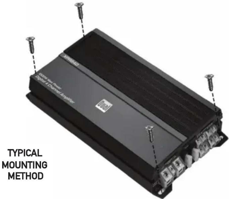
- Choose a mounting location for the amplifier. Suggested locations include under a seat or in the trunk.
- The amplifier can be mounted horizontal (recommended) or vertical. For optimum performance, make sure to provide at least 1" of space around all sides. Do not mount the amplifier under carpets or where airflow is restricted.
- Do not install the amplifier where it may be exposed to moisture.
- The optimum mounting location varies between vehicles. Remember to test all amplifier functions before completing the final mounting procedure.
Connection Descriptions
NOTE:
Be sure to follow specific instructions included with your amplifier installation kit (not included with this amplifier). The information below should be used as a general guideline only.
Power Wire (+12V)
- Disconnect negative battery terminal before proceeding. Consult a qualified technician for instructions if you are unsure.
- Plan wire routing before cutting any wires to length. Begin by routing the power +12V wire from the battery to the amplifier location. Use a grommet when running wires through the firewall or metal openings. Avoid running the power wire near existing vehicle wiring to prevent induced noise from entering the audio system.
- Use extreme caution when drilling holes to avoid damaging fuel lines or existing vehicle wiring.
- The +12V wire MUST be fused within 18" of the battery for protection of the vehicle's electrical system.
Ground Wire (GND)
- The amplifier ground wire should be as short as possible (no more than 36" or 1 meter). Choose a clean unpainted section of metal or the vehicle chassis when attaching the ground connection. Be sure to clean the area of any dirt or grease.
Remote Turn-on Wire (REM)
- The remote turn-on wire connects to the head unit's amplifier turn-on lead or power antenna output.
Speaker Wires
- Choose adequate gauge speaker wire depending on your exact amplifier/speaker combination. Be sure to observe polarity when connecting.
- Do not ground any speaker wires or connect any speaker wires together.
Input Signal
- The amplifier's input signal connects to the head unit's low level (RCA) or high level (speaker wire) outputs.
- Low level input signals deliver the best performance. If unavailable, use the high level inputs - when interfacing with factory head unit for instance.
CAUTION
- Do not use both low and high level inputs at the same time. Connect only one or the other.
- Keep low level inputs away from any power wires to avoid engine noise.
- Never run any wires underneath or outside the vehicle.
Audio Inputs and Controls
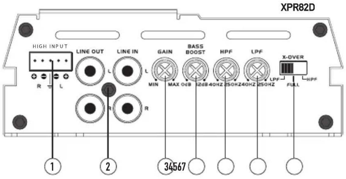
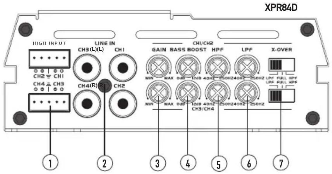
① High-Level Inputs (Speaker Wire)
② Line In / Line Out (RCA)
③ Gain
4 Bass Boost
⑤ High-Pass Filter
6 Low-Pass Filter
⑦ Crossover Control
Power and Speaker Connections
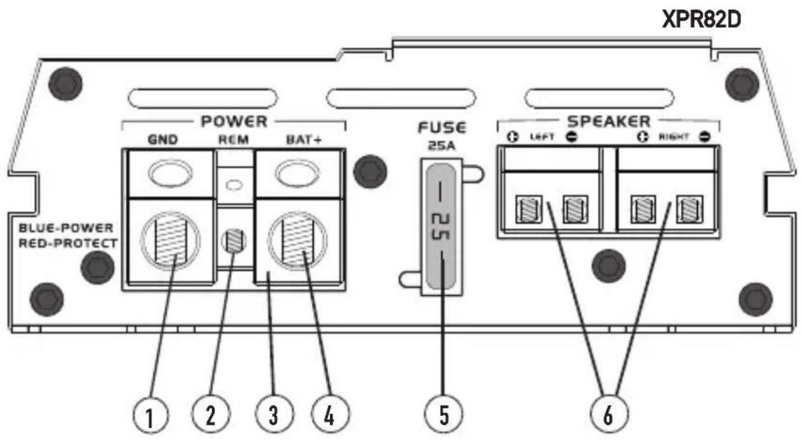
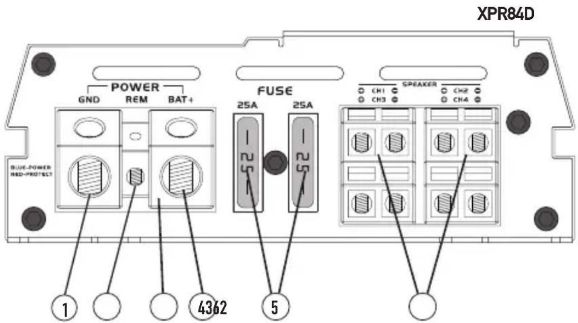
① Ground Connection
② Remote Turn On
3 Power/Protect LED
4 +12VDC Battery Connection
⑤ Fuse(s)
6 Speaker Connections
INSTALLATION
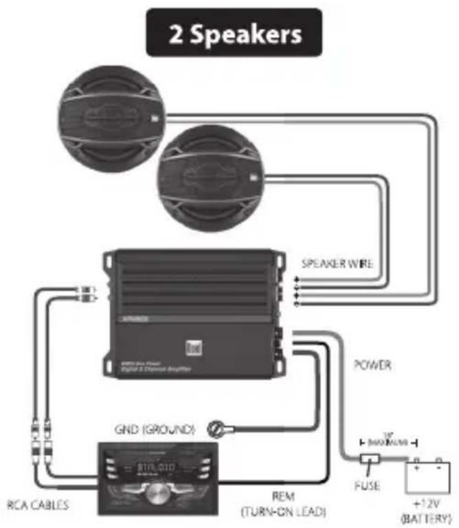
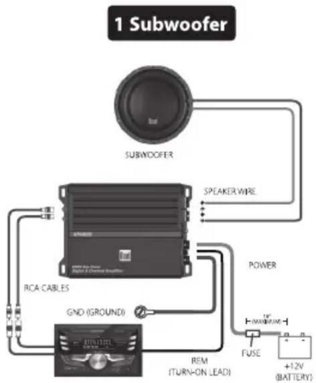
Typical Wire Routing
XPR82D
flowchart
graph TD
    A["Speaker 1"] --> B["Speaker Wire"]
    C["RCA CABLES"] --> D["GND (GROUND)"]
    E["REMARKS"] --> F["Power"]
    F --> G["FUSE"]
    G --> H["+12V (BATTERY)"]
    I["SPEAKER WIRE"] --> A
    J["+12V (BATTERY)"] --> H
Speakers, head unit, wiring kit, and speaker wire sold separately.
flowchart
graph TD
    A["1 Subwoofer"] --> B["SUBWOOFER"]
    B --> C["Speaker Wire"]
    C --> D["RCA CABLES"]
    D --> E["GND (GROUND)"]
    E --> F["Power"]
    F --> G["FUSE"]
    G --> H["+12V (BATTERY)"]
    H --> I["REM (TURN-ON LEAD)"]
    I --> J["Ground"]
Subwoofer, head unit, wiring kit, and speaker wire sold separately.
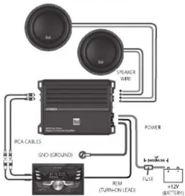
2 Subwoofers
flowchart
graph TD
    A["Speaker"] --> B["Amplifier"]
    C["Speaker"] --> B
    B --> D["GND (GROUND)"]
    D --> E["Power"]
    E --> F["FUSE"]
    F --> G["+12V (BATTERY)"]
    H["RCA CABLES"] --> B
    I["REMARKER WIRE"] --> B
    J["POWER"] --> K["FUSE"]
    L["Ground"] --> M["REMARKER WIRE"]
    style A fill:#f9f,stroke:#333
    style C fill:#f9f,stroke:#333
    style H fill:#ccf,stroke:#333
    style I fill:#ccf,stroke:#333
    style J fill:#ccf,stroke:#333
    style K fill:#ccf,stroke:#333
    style L fill:#ccf,stroke:#333
    style M fill:#ccf,stroke:#333
Speakers, subwoofer, head unit, wiring kit, and speaker wire sold separately.
Main Power Connections
The illustrations on pages 6 and 7 demonstrate three different wiring options for each unit. Once desired configuration has been selected, connect the +12V, GND and REM wires accordingly. A suitable fuse MUST be installed on the +12V lead within 18" of the battery for protection of the vehicle's electrical system.
Typical Wire Routing
XPR84D
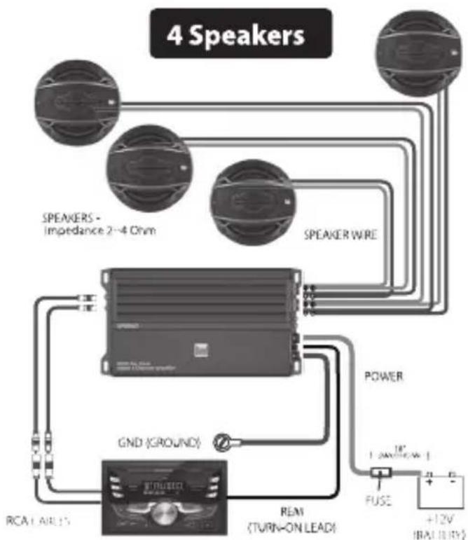
flowchart
graph TD
    A["Speaker - Impedance 2~4 Ohm"] --> B["Speaker Wire"]
    C["RCA / AIR / S"] --> D["GND (GROUND)"]
    D --> E["Power"]
    E --> F["FUSE"]
    F --> G["+12V (BAT LIRY)"]
    H["REMI (TURN-ON LEAD)"] --> D
    I["SPEAKERS - Impedance 2~4 Ohm"] --> B
    J["+12V (BAT LIRY)"] --> G
Speakers, head unit, wiring kit, and speaker wire sold separately.
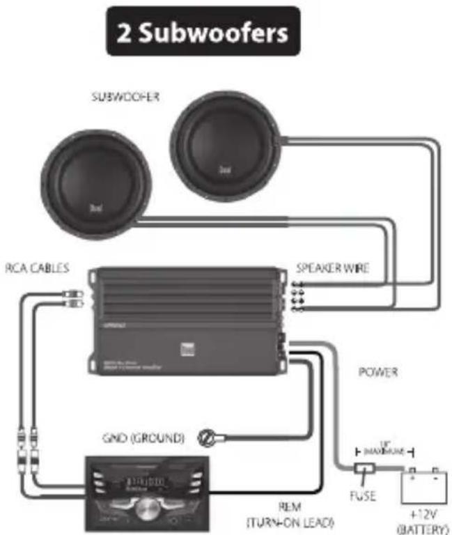
flowchart
graph TD
    A["Subwoofer"] --> B["RCA CABLES"]
    A --> C["SPEAKER WIRE"]
    A --> D["GND (GROUND)"]
    A --> E["REM (TURN-ON LEAD)"]
    A --> F["FUSE"]
    F --> G["+12V (BATTERY)"]
    H["Power"] --> I["Speaker Wire"]
    I --> A
    J["+12V (BATTERY)"] --> K["FUSE"]
    K --> F
Subwoofer, head unit, wiring kit, and speaker wire sold separately.
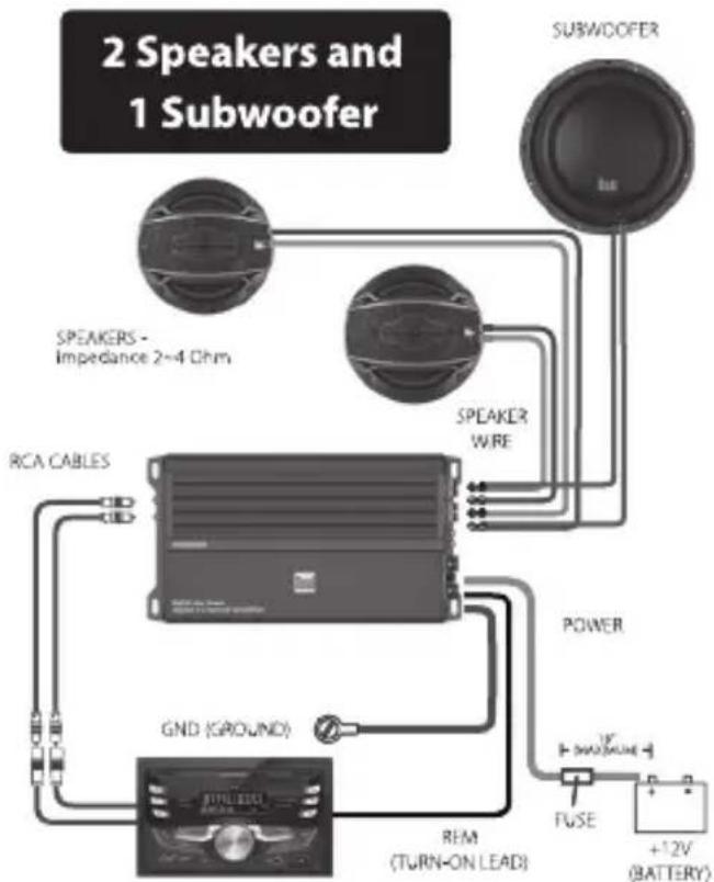
flowchart
graph TD
    A["2 Speakers and 1 Subwoofer"] --> B["SPEAKERS - Impedance 2~4 Ohm"]
    A --> C["SPEAKER WIRE"]
    A --> D["RCA CABLES"]
    A --> E["GND (GROUND)"]
    A --> F["REM (TURN-ON LEAD)"]
    A --> G["FUSE"]
    G --> H["+12V (BATTERY)"]
    A --> I["SUBWOOFER"]
    I --> J["Power"]
    J --> K["FUSE"]
    K --> L["+12V (BATTERY)"]
Speakers, subwoofer, head unit, wiring kit, and speaker wire sold separately.
Fuse Rating
When replacing fuses, make sure new fuse is the correct type and amperage. Using an incorrect fuse could damage the amplifier.
XPR82D - 25A
XPR84D - 25Ax2
Power/Ground Wire Size
For optimum performance, use only the wire size listed below or larger. Make sure to use the same size power and ground wire.
XPR82D - 8 awg
XPR84D - 8 awg
Amplifier Connections
Speaker Connections
Connect speaker wires observing polarity. The minimum impedance load for the amplifiers is 2 ohms stereo and 4 ohms bridged. Use of loads lower than these is not recommended and may cause amplifier damage. The amplifiers can be wired for stereo, bridged or stereo/bridged simultaneous operation.
2 Speakers (stereo)
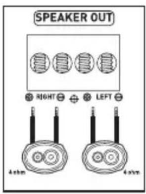
Typical Stereo Wiring (2 ohms minimum)
Speakers (bridged)
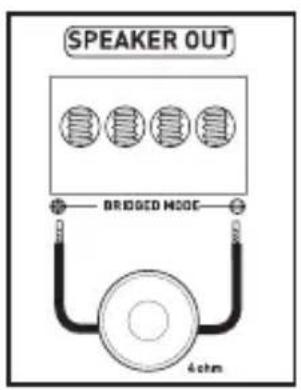
Typical Bridged Wiring (4 ohms minimum)
Input Signal Connections
Low Level Input (RCA)
Low level (RCA) input signal is preferred for best performance. Typical trunk-mount amplifier installations require a 17-20 foot RCA cable. Most trucks and under-seat applications require a 6-9 foot RCA cable. Using twisted pair construction RCA cables will minimize noise.
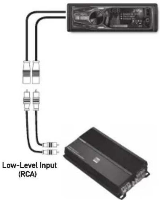
Note: Do not use both low and high level inputs at the same time - connect only one or the other.
High Level Input (Speaker Wire)
High level inputs should only be used when RCA outputs are not available from the head unit. Connect the head unit speaker outputs to the high level input connector as shown below. The black wire (signal reference ground) may or may not require a connection to chassis ground - depending on your particular installation.
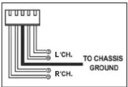
INSTALLATION
Configuration/Setup
Input level Control
The input level control (gain) is used to obtain the best possible match between the head unit audio output and the amplifier input. Begin by turning the input level control fully counterclockwise. Next, turn up the head unit volume control around 3/4 of the way up. Adjust the input level control clockwise until audible distortion is heard, then slightly counterclockwise to provide the best match. Repeat for all input level controls.
Crossover Mode
The crossover is used to filter out frequencies above or below a certain point. Choose LPF when using the amplifier with subwoofers, HPF when using with midrange/tweeter combinations and FULL when using with coaxial-type speakers.
Note: Choose FULL when using the amplifier in stereo/bridged simultaneous mode. In this mode, passive crossovers are required. Failure to use the correct passive components may damage the amplifier and/or speakers. Consult a qualified professional for recommendations.
Crossover Control
This control allows precise adjustment of the crossover frequency.
Bass Boost
This control provides additional boost @ 45Hz when used with subwoofers. Adjust this control with caution - as improper use can damage speakers!
Power / Protect Indicators
Colored LED indicators illuminate from the plastic power terminal. The blue LED illuminates during normal operation (POWER) and the red LED indicator is visible when the amplifier detects a fault (PROTECT).
INSTALLATION
Specifications
XPR82D
Power Output
• 80 Watts x 2 channels @ 4 Ohms
• 120 Watts x 2 channels @ 2 Ohms
• 240 Watts x 1 channel (bridged)
Peak Music Power Output: 600 Watts
Signal to noise ratio: > 100dB
Frequency response: 20Hz -20kHz
Amplifier dimensions: 7.2" x 5.0" x 1.8" (182.5 x 127 x 46 mm)
XPR84D
Power Output
• 80 Watts x 4 channels @ 4 Ohms
• 120 Watts x 4 channels @ 2 Ohms
• 240 Watts x 2 channels (bridged)
Peak Music Power Output: 1000 Watts
Signal to noise ratio: > 100dB
Frequency response: 20Hz- 20kHz
Amplifier dimensions: 9.4" x 5.0" x 1.8" (237.5 x 127 x 45 mm)
Troubleshooting
| Problem Cause Action | ||
| Unit will not turn on (no power LED indicator) | +12V wire not connected or incorrect voltage. REM wire not connected or incorrect voltage | Check connections for proper voltage (11~16VDC) |
| GND wire not connected Check connection to ground | ||
| Fuse(s) blown Replace fuse(s) | ||
| Unit has power - LED is green (but no sound) | Speaker wires not connected Check connections at speakers | |
| Volume turned all the way down Increase volume level at head unit | ||
| One or more speaker wires touching each other or touching chassis ground | Insulate all bare speaker wires from each other and chassis ground | |
| Speaker(s) defective or damaged Check/replace speaker(s) | ||
| Input signal not connected | Check high or low level inputs for proper connection | |
| Unit blows fuse(s) | Incorrect fuse rating Use fuse(s) with correct rating | |
| +12V wire touching chassis ground Check for pinched wire | ||
| Speaker(s) defective or damaged Check/replace speaker(s) | ||
| Engine noise | Bad ground connection | Make sure amplifier is grounded to clean bare metal |
| Signal ground loop or RFI (radio frequency interference) | Re-route RCA cables from existing high current wiring | |
| LED illuminates red (protect mode) | One or more speaker wires touching each other or touching chassis ground | Insulate all bare speaker wires from each other and chassis ground |
| Speaker(s) defective or damaged internally (shorted) | Check/replace speaker(s) | |
| Speaker load less than 2 ohms (stereo). Speaker load less than 4 ohms (bridged) | Adjust speaker load - amplifier will not operate at less than 4 ohms when bridged | |
| Distorted audio output | Incorrect input signal type or input level too high | Check connections and reduce/adjust input level |
| Low audio output | Incorrect input signal type or input level too low | Check connections and increase/adjust input level |
One-Year Limited Warranty
This warranty gives you specific legal rights. You may also have other rights which vary from state to state.
Dual Electronics Corp. warrants this product to the original purchaser to be free from defects in material and workmanship for a period of one year from the date of the original purchase.
Dual Electronics Corp. agrees, at our option, during the warranty period, to repair any defect in material or workmanship or to furnish an equal new, renewed or comparable product (whichever is deemed necessary) in exchange without charges, subject to verification of the defect or malfunction and proof of the date of purchase. Subsequent replacement products are warranted for the balance of the original warranty period.
Who is covered? This warranty is extended to the original retail purchaser for products purchased from an authorized Dual dealer and used in the U.S.A.
What is covered? This warranty covers all defects in material and workmanship in this product. The following are not covered: software, installation/removal costs, damage resulting from accident, misuse, abuse, neglect, product modification, improper installation, incorrect line voltage, unauthorized repair or failure to follow instructions supplied with the product, or damage occurring during return shipment of the product. Specific license conditions and copyright notices for the software can be found via www.dualav.com.
What to do?
-
Before you call for service, check the troubleshooting guide in your owner's manual. A slight adjustment of any custom controls may save you a service call.
-
If you require service during the warranty period, you must carefully pack the product (preferably in the original package) and ship it by prepaid transportation with a copy of the original receipt from the retailer to an authorized service center.
-
Please describe your problem in writing and include your name, a return UPS shipping address (P.O. Box not acceptable), and a daytime phone number with your shipment.
-
For more information and for the location of the nearest authorized service center please contact us by one of the following methods:
• Call us toll-free at 1-866-382-5476
• E-mail us at cs@dualav.com
Exclusion of Certain Damages: This warranty is exclusive and in lieu of any and all other warranties, expressed or implied, including without limitation the implied warranties of merchantability and fitness for a particular purpose and any obligation, liability, right, claim or remedy in contract or tort, whether or not arising from the company's negligence, actual or imputed. No person or representative is authorized to assume for the company any other liability in connection with the sale of this product. In no event shall the company be liable for indirect, incidental or consequential damages.
INSTALLATION
Notes

Details and specifications mentioned in this document may be updated and subject to change without notice. To access the latest document, please check the product website.
Dual Electronics Corp.
Toll Free: 1-866-382-5476
Monday-Friday, 9AM-5PM, EST
www.dualav.com
©2017 Dual Electronics Corp.
NSC0717-V01
- XPR82D-XPR84D
- INSTALLATION
- Preparation
- Before You Start
- Mounting Location
- Connection Descriptions
- NOTE:
- Power Wire (+12V)
- Ground Wire (GND)
- Remote Turn-on Wire (REM)
- Speaker Wires
- Input Signal
- CAUTION
- Typical Wire Routing
- XPR82D
- Main Power Connections
- XPR84D
- Fuse Rating
- Power/Ground Wire Size
- Amplifier Connections
- Speaker Connections
- Input Signal Connections
- Low Level Input (RCA)
- High Level Input (Speaker Wire)
- Configuration/Setup
- Input level Control
- Crossover Mode
- Crossover Control
- Bass Boost
- Power / Protect Indicators
- Specifications
- Power Output
- One-Year Limited Warranty
- What to do?
- Notes
Brand : DUAL
Model : XPR82D
Category : Receiver