
MIM-B17N - Air conditioner SAMSUNG - Free user manual and instructions
Find the device manual for free MIM-B17N SAMSUNG in PDF.


| Product Type | Wired Remote Controller |
| Model | MIM-B17N |
| Brand | Samsung |
| Compatible Systems | Samsung DVM S, DVM Chiller, and other compatible HVAC systems |
| Dimensions (W x H x D) | 120 mm x 80 mm x 20 mm (approx.) |
| Weight | 150 g (approx.) |
| Power Supply | 3 V DC (2 x AAA batteries, not included) or via communication cable from indoor unit |
| Display Type | LCD with backlight |
| Control Functions | On/Off, Mode (Cool/Heat/Fan/Dry/Auto), Temperature setting, Fan speed (Low/Med/High/Auto), Airflow direction (Swing), Timer (On/Off), Sleep mode |
| Communication Protocol | Wired (RS-485 or proprietary) |
| Maximum Cable Length | Up to 100 m (depending on installation) |
| Operating Temperature | 0 °C to 50 °C |
| Storage Temperature | -20 °C to 60 °C |
| Mounting Type | Wall-mounted (flush or surface) |
| Included Accessories | Mounting frame, screws, communication cable (if applicable) |
| Maintenance | Clean with a soft dry cloth; avoid water and solvents |
| Battery Replacement | Replace two AAA batteries when low battery indicator appears |
| Safety Features | Child lock, overheat protection (external) |
| Repairability | Spare parts available through Samsung service centers; professional repair recommended |
Frequently Asked Questions - MIM-B17N SAMSUNG
User questions about MIM-B17N SAMSUNG
0 question about this device. Answer the ones you know or ask your own.
Ask a new question about this device
Download the instructions for your Air conditioner in PDF format for free! Find your manual MIM-B17N - SAMSUNG and take your electronic device back in hand. On this page are published all the documents necessary for the use of your device. MIM-B17N by SAMSUNG.
USER MANUAL MIM-B17N SAMSUNG
Air Conditioner User Manual
Imagine the possibilities
Thank you for purchasing this Samsung product.
Safety Precautions
English
- Before using the DMS2, read these instructions carefully.
- After reading the instructions, keep this user's manual in a handy and safe place. If the user changes, you must hand over the manual.
- Never attempt to install the air conditioning system or to move the DMS2 by yourself.

WARNING
◆ Do not attempt to install or repair this DMS2 by yourself. ◆ This DMS2 contains no user-serviceable parts. Always consult authorized service personnel for repairs. - When moving, consult authorized service personnel for disconnection and installation of the DMS2. ◆ Ensure that the wall is strong enough to support the weight of the DMS2. ◆ Must install the DMS2 with rated power supply. In the event of a malfunction (burning smell, etc.), immediately stop operation, turn off the electrical breaker, and consult authorized service personnel. ◆ Do not use inflammable gases near the DMS2. ◆ Do not spill water into the DMS2. ◆ Do not operate the DMS2 with wet hands. Do not install the DMS2 in a location where it will come into contact with combustible gases, machine oil, sulfide gas, etc. ◆ Do not press buttons with a pointed object. ◆ Do not pull or bend the DMS2 cable excessively. ◆ Do not use this DMS2 for other purposes. ◆ Do not spray insecticide or other combustible things on the DMS2. ◆ Do not clean the DMS2 with benzene, solvents, or other chemicals. ◆ Do not give a shock to the DMS2 or disassemble it by yourself.

CAUTION
◆ The contents and pictures used in this user manual may be changed without advance notice for the functional reinforcement and improvement of a product.

This system is strictly restricted to authorized users. Any illegal access shall be punished with related law.
Introduction of DMS2 (Data Management Server2)
The DMS2 is an Ethernet based device for central management of Samsung system air-conditioners. It operates 24 hours without a separate management (PC).
Advantages of DMS2 System
The DMS2 provides the following advantages:
◆ Everyday Device – The DMS2 is operational all year long, 24 hours. ◆ Independent Operation – The DMS2 can operate schedule control and power distribution without a PC. Note: In order to run power distribution, relevant controllers need to be installed.
◆ Remote Control
√ Web – The DMS2 has a built-in web server function and can be accessed from a remote location to operate status monitoring, control, trouble history, and schedule setting of the system air-conditioners. √ Using an Upper Level Controller – When a separate upper level controller (S-NET series) is used, a number of DMS2 can be controlled with one central management system.
◆ Data Storage – The DMS2 has its own database built-in, therefore, trouble history, indoor unit installation information, and power distribution data can be saved and retrieved.
◆ Large Scale Management – At most 256 indoor units can be connected to one DMS2 and therefore, only one DMS2 can manage small and medium size buildings.
◆ Automatic "e-mail" sending – When an error occurs, inform the error details to an e-mail saved on DMS2.
Note
◆ Please be advised that once you are permitted access to the system, you will be deemed to have consented to having software relating to this system automatically updated or modified on a periodic basis.

Terms
◆ DMS2: The abbreviation of Data Management Server2. ◆ Upper Controller: S-NET 3, RMS(ZenManager) and DMS2 which allows controlling by accessing to a web page. ◆ OnOff Controller: A device that controls 16 groups of the DVM air conditioner. A central control device of a DVM system which is located between a DMS2 and an outdoor unit. ◆ AHU(Air Handling Unit): Executes heat exchange between air and cooling unit using central air conditioning duct method. ◆ ERV(Energy Recovery Ventilator): Ventilating system using heat recovery function.
Viewing the Parts
Front View

| No. | Name Description | |
| 1 | LCD Display Display current time/ Check menu | |
| 2 | Menu button Access to main menu | |
| ▼/▲ button | Select the function you want and set detailed functions in main menu | |
| Set button | Check the function you want from main menu and select it | |
| 3 | Bottom cover | Unfasten 2 screws on the bottom and separate the bottom cover from DMS2. Then check cable connection part. |
Indicator

| Name Description | |
| Power Turns blue when the power is supplied. | |
| CPU Alive | Blinks in orange with 1 second intervals during normal operation. |
| Ethernet-Linked Turns green during normal connection. | |
| Ethernet-Active Blinks in orange during normal transmission/reception. | |
| COM1~5 – TX Blinks in green during normal transmission. | |
| COM1~5 – RX Blinks in green during normal reception. | |
| Check Turns green when notice occurs. | |

Bottom View
Separate the bottom cover by unfastening the 2 screws on the bottom.

Socket for sub memory (SD or MMC)
(Sub memory is for DMS2 program update and set information saving)
Purchase SD card separately.

System Configuration
![graph TD A["S-NET 3"] -->|TCP/IP| B["DMS2"] B --> C["Internet"] C --> D["Web Client"] B --> E["OnOff controller"] B --> F["Touch Centralized controller"] F --> G["Outdoor Unit"] G --> H["Max 256 Indoor units (DVM Series)"] G --> I["Power meter"] H --> J["Sim/PIM"] I --> J J --> K["RMS Senter"] style…](/content/2026/05/947375/images/2840794387c5237fae30f9067077fd1ed6965e32677dc229631a135c7db9ea46.jpg)
Connecting outdoor unit and DMS2
You can control up to 80 outdoor units and 256 indoor units by using DMS2.
You can connect up to 16 outdoor units per each communication channel of the DMS2.
If the number of connected outdoor units increases, it may take longer for tracking.

CAUTION
For devices that support new communication, you must set the communication mode of the channel to 'NEW' from [System settings → Tracking] menu. Indoor/outdoor units with conventional communication type cannot be connected to DMS2 with new communication. When 'NEW' is set as communication mode of the channel, virtual OnOff controller address will be assigned. (Channel 0: Virtual OnOff controller 11, Channel 1: Virtual OnOff controller 12, Channel 2: Virtual OnOff controller 13, Channel 3: Virtual OnOff controller 14, Channel 4: Virtual OnOff controller 15) The maximum number of indoor units that can be connected to each communication channel of DMS2 RS485 is 128.
Web Browser Specification
Windows 7 or later version. Install Internet Explorer 7.0 or later version. You can use Internet Explorer 6.0 but it is not recommended. Install Silverlight 2.0 or later version.
Note
Visit the internet homepage (http://www.microsoft.com/silverlight/) to download Silverlight. Alternatively, you can download it through the download link that appears automatically when the PC is connected to the Internet and you access DMS2 for the first time. ◆ Silverlight operates normally with Windows XP SP2 or later versions. It may not operate normally with earlier versions of Windows.
Computer Settings for DMS2 Connection
All settings of DMS2 will be arranged in the web page built into DMS2.
You should access the DMS2 IP to use the DMS2 web page.
There are 2 ways to access the DMS2 IP.
(For settings, refer to the installation manual.)
◆ Static IP setting ◆ Dynamic IP (DHCP) setting ◆ Basically, only Private IP can be set as the IP address. To use Public IP, you must set 'Enable public IP' to 'Enable' from the menu [System Settings] → [System environment setting]. - Private IP range: 10.0.0.0 ~ 10.255.255.255, 172.16.0.0 ~ 172.31.255.255, 192.168.0.0 ~ 192.168.255.255

CAUTION
Use this product only in a separate dedicated network. Samsung Electronics is not liable for any problems caused by connecting it to the Internet or an intranet.
Interface with Upper Level Controller
The DMS2 receives/manages setting and control data from the upper level controller and sends the received data to the lower level system.
◆ Upper controller: S-NET 3, RMS, and DMS2, which allows controlling by accessing a web page. ◆ S-NET 3: System air conditioner controlling and monitoring program that is installed on a PC. ◆ RMS (ZenManager): A device that supervises operation status and breakdown status by connecting to DMS2 for system air conditioner remote service. If a breakdown is detected, it notifies the service agent and enables fast service.
Save Trouble History
The DMS2 saves at most 1024 cases of trouble history. If the number of errors exceeds 1024, only the latest 1024 cases are stored by deleting the oldest trouble history.
◆ Device name, address, error occurrence time, error resolution time, and trouble history will be saved. You can check them on the web page or upper controller. - When an error occurs, it sends the trouble history to the e-mail saved in DMS2.
| Device Type | |
| Indoor Unit | Indoor unit communication errorIndoor unit sensor related errorOther errors |
| Outdoor Unit | Outdoor unit communication errorPipe inspection errorOutdoor unit sensor related errorOutdoor unit related other errors |
| Communication error such as OnOff controller | Control device related communication error |
Set and Run Schedule
The schedule function of the DMS2 can be set through the Web or using the upper level controller. 1-day, everyday, and every-week schedules can be set.
◆ Each schedule can be used selectively by using the run schedule/stop schedule order. ◆ At most 256 schedules can be set. - Indoor unit control is possible at least 1 minute of interval by set schedule.
| Item Content Remark | ||
| Schedule Period Starting and ending date of a schedule | ||
| Exception Day Setup | Set an exception day within a schedule period to ignore the schedule control | |
| Devices to be applied | Select devices to receive schedule control | |
| Event | Set indoor unit operation modes- Device On time- Device Off time- Desired temperature- Operation mode: Auto/Cool/Dry/Fan/Heat/Off- Remote control usage Enable RC/ Disable RC/Cond.RC- Fan speed: Auto/Low/Mid/High- Air flow: None/Vertical/Horizontal/All- ERV operation mode: Auto/HeatEx/ByPass/Sleep- ERV Fan speed: Low/High/Turbo | Weekly Repeat:Maximum 10 events per dayDaily Repeat:Maximum 70 events |
Main Function (Continued)
Save Integrated Power Distribution Data
The DMS2 calculates and distributes the power consumed by each indoor unit by receiving the total power usage from the watt-hour meter interface modules (SIM/PIM) and taking into account the operation status of the indoor units.
The DMS2 saves at most 1 year of data. After a year, the oldest data is deleted and the latest data is saved. This data can be checked through the built-in Web page of the DMS2 or by S-NET 3.
System Architecture
![graph TD A["S-NET 3"] -->|TCP/IP| B["DMS2"] B --> C["Internet"] B --> D["Web Client"] B --> E["RMS Senter"] B --> F["OnOff controller"] B --> G["Touch Centralized controller"] G --> H["Outdoor Unit"] H --> I["Max 256 Indoor units (DVM Series)"] H --> J["Power meter"] H --> K["Sim /PIM"] H --> L["SIM…](/content/2026/05/947375/images/e8e374dc0b56ff198d43ef314eab70f685aa41728aa70d89b352fceec3ebe19e.jpg)
Time Segmentation
◆ Time segmentation is used to divide 24 hours into different sections and to distribute power according to each section. This function is used when the power consumption fee is different according to different time slots or when a building is charged differently depending on the consumption time. ◆ 1 section (A) is set as 24 hours, and the factory default setting is set as 1 section. The time, 24 hours, can also be divided into 2 sections (A, B, A), 3 sections (A, B, C, A) or 4 sections (A, B, C, D, A) ◆ DMS2 shows the result of the power distribution for each section you set.

Input manually (When setting 2 sections, 3 sections, and 4 sections)

If communication error occurs between DMS and the lower level controllers, actual power consumption and the result of power distribution value may not be same. Make sure to solve communication error status.
- Example of communication error: Communication error between DMS2 and SIM(PIM)/SIM(PIM) and watt hour meter/DMS2 and outdoor unit/indoor and outdoor units.
Starting DMS2
Current time setting
Set the current time of DMS2 system.
◆ "2009/01/01 01:01:01" is factory setting. Set the current time as DMS2 system time. You can set DMS2 time in [System Settings] → [System environment setting] (Refer to page 127~128)

If DMS2 time does not set as the current time, DMS2 may cause malfunction when using Schedule or control logic management.
Connecting OnOff controller & outdoor unit
Connecting devices
(1) Make sure the connection of communication cables(R1/R2) between DMS2 and other devices such as outdoor units, control devices. (2) Execute tracking.
◆ DMS2 communicates with outdoor unit and brings information about installed indoor unit and outdoor unit. ◆ After tracking, you can use indoor unit control and other menu. ◆ For tracking, refer to [System Settings] → [Tracking] (Refer to page 144~148)

Access to DMS2 & Login

1 Run internet explorer on your computer.
2 Enter IP address (http://192.168.0.100) on the address bar, and then press [ENTER].
If it is the first access to DMS2, "Install Microsoft Silverlight" message will be displayed. - The message will not appear if Microsoft Silverlight have already installed. If the message window and login screen does not appear, check PC setting status.
3 Click [Run] and continue installation.
◆ Access to DMS2 again after installation.

4 Enter ID and password when DMS2 main web page appears. Then click [LOGIN].
◆ The default DMS2 user ID is 'admin' and password is 'ac0530'. ◆ Depending on authorization settings which set by the administrator, access to some functions may be restricted. ◆ To edit user authorization, refer to [System Settings]→ [User authorization management]. (Refer to page 110)
Note: Only authorized users can access the web page. Fewer than 5 concurrent users are recommended because connection speed may slow down. The DMS2 manager should change the ID and password for security and management. (Refer to page 108) Logout: To log out, click [LOGOUT] at the top of the menu.

Silverlight will run normally with Windows XP SP2 or later. With earlier versions of Windows, DMS2 may not operate normally.
Logged-in User with No Authorization

1. When the screen above appears, ask the manager for help.
Depending on the control authorization setting, there may be a user who does not have control authorization. The above screen will appear when the logged-in user does not have control authorization.
Devices Controlled and Monitored by DMS2
| Type Display | Remote controller (Controlling range) | Type Display | Remote controller (Controlling range) | |||
| Indoor unit display icon |  |  | MINI AHU display icon |  |  | |
| ERV display icon |  |  | Fresh duct display icon |  |  | |
| AHU display icon |  |  | DI (Digital Input) display icon |  |  | |
| ERV PLUS display icon |  |  | DO (Digital Output) display icon |  |  | |
| Hydro Unit, Single EHS display icon |  |  |  | Hydro Unit HT, display icon |  |  |
DMS2 can control and monitor the devices listed in the table above.

When users select multiple devices, 'Basic Control' will be displayed on the screen. (This occurs when multiple devices of different types are selected.)
Monitoring Indoor Unit Operation Status

1. Click [Control and Monitoring] when the DMS2 web page menu screen appears. The [Control and Monitoring] screen will appear when you log in to the DMS2 web page.
2. Check the current status of all devices.
You can check the current controlling status of all installed indoor units, ERV, AHU, ERV PLUS, Fresh duct, MINI AHU, Hydro Unit, Hydro Unit HT, Single EHS, and other devices.
Note
When advanced functions (such as Sleep mode, Energy saving function) are selected through wired/wireless remote controllers or the indoor unit panel, the operation mode set on the remote controllers and DMS2 may be displayed differently. Also, when controlling by DMS2, additional functions will be canceled. Depending on the model of indoor unit, Horizontal/All air flow direction control may not be possible. In this case, vertical or fixed flow will be displayed depending on the indoor unit's basic operation specification. AHU, ERV, ERV PLUS, Fresh duct, MINI AHU, Hydro Unit, Hydro Unit HT, Single EHS, and other devices will be displayed only when the corresponding devices are installed.

Some functions available on the DMS2 web page may not be functional at BACnet Gateway and LonWorks Gateway. For detailed functions, refer to the installation manual or contact Samsung Electronics.
Control and Monitoring (Continued)
Controlling an Indoor Unit

1 Click [Control and Monitoring] when DMS2 web page menu screen appears.
◆ [Control and Monitoring] screen will appear when you log-in to DMS2 web page.
2 Select an indoor unit to control.
◆ Check the indoor unit status through status display window. - When the selected indoor unit is switched on, the remote controller panel will be automatically activated.
3 Turn the indoor unit on by clicking [☐]
◆ Remote controller panel will be activated.

4 Select the operation mode.
◆ You can select Auto, Cool, Dry, Fan and Heat operation mode.
5 Click [▲][▼] to set the desired temperature.
◆ Each time you press the buttons, the temperature will be adjusted by 1 or 0.1°C (or by 1°F). If Auto/Cool/Dry mode is in operation, you can adjust the desired temperature in the range of 18°C(64°F)\~30°C(86°F). If Heat mode is in operation, you can adjust the desired temperature in the range of 16°C(61°F) ~ 30°C(86°F). ◆ You cannot adjust the desired temperature in Fan mode. When the operation mode of an indoor unit is Cool or Dry mode, you cannot set the desired temperature lower than lower limit temperature if lower limit is enabled. When the operation mode of indoor unit is Heat mode, you cannot set the desired temperature higher than upper limit temperature if upper limit is enabled.
6 Select the fan speed.
◆ You can select Auto, Low, Mid and High. ◆ If Auto/Dry mode is in operation, fan speed will be set as Auto fan speed. ◆ If Fan mode is in operation, you cannot select Auto fan speed.
Control and Monitoring (Continued)

7 Select the air flow.
You can select Vertical, Horizontal, All, and None air flow direction.
8 Set remote controller settings.
You can select Enable RC, Disable RC, and Cond. RC. When selecting [Disable RC], indoor unit control by wired/wireless remote controller and indoor unit panel is not possible. Indoor unit control is only available in DMS2 web page. Click [💡] when you want to use wired remote controller in each room.
9 Select SPI setting.
You can set SPI through button activation / non activation.
10 Select MDS setting.
You can set MDS (Motion Detection Sensor) through button activation / non activation.
11 Set cooling/heating discharge temperature by clicking [▲] and [▼].
When the indoor unit is in Cool mode, you can adjust cooling discharge temperature and when the indoor unit is in Heat mode, you can adjust the heating discharge temperature. When the indoor unit is in Auto, Dry or Fan mode, you cannot adjust the discharged temperature. Cooling discharged temperature can be set in the range of 8°C (46°F) to 18°C (64°F). Heating discharged temperature can be set in the range of 30°C (68°F) to 43°C (109°F).
12 Select [Control Discharge Temp].
You can enable/disable button to decide whether to use discharge temperature adjustment.
Note: When filter warning sign is displayed on indoor unit status window
Select the indoor unit and click [Reset filter]. Filter warning will be released.

Make sure that each indoor unit must be turned on to control. Selecting remote controller, reset filter, operation mode limits, setting lower/upper temperature limit are possible even if the power of indoor unit is off. Some air flow direction option may be restricted depending on the indoor unit model. SPI, MDS and discharge temperature functions can be operated normally when corresponding optional functions are installed to the selected indoor unit.
Control and Monitoring (Continued)
Indoor Unit Operation Mode Limit

You can monitor the operation status of all indoor units or have individual or whole control of the indoor units.
1. Click [Control and Monitoring] when the DMS2 web page menu screen appears.
◆ The [Control and Monitoring] screen will appear when you log in to the DMS2 web page.
2. Select an indoor unit to control.
◆ Check the indoor unit status through the status display window.
- When the selected indoor unit is switched on, the remote controller panel will be automatically activated.

3. Set operation mode limit.
◆ You can select [Cool Only (Cool)], [Heat Only (Heat)], and [No Limits]. - No limits: You can use cool mode and heat mode with no limits.
Note: ◆ Operation mode limits setting is not available in ERV.

CAUTION
If you set the operation mode limit, DMS2 will automatically change the operation mode limit setting of all the indoor units connected to the same outdoor unit. ◆ If the indoor unit is a cooling-only model, you cannot set the operation mode limit to 'Heat Only'.
Setting Lower/Upper Temperature Limit of an Indoor Unit

You can monitor the operation status of all indoor units, and control the indoor units as a whole, or as individual units.
1. Click [Control and Monitoring] when the DMS2 web page menu screen appears.
◆ The [Control and Monitoring] screen will appear when you log in to the DMS2 web page.
2. Select an indoor unit to control.
◆ Check the indoor unit status through the status display window.
When the selected indoor unit is switched on, the remote controller panel will be automatically activated.

3. Set the upper temperature limit by pressing [▲] and [▼].
◆ Click 'Heat upper limit' to apply the upper temperature limit setting. ◆ The upper temperature limit can be set in the range of 16°C (61°F) to 30°C (86°F). When an indoor unit is operating in Heat mode and the upper temperature limit is applied, you cannot set the desired temperature higher than the upper temperature limit.
4. Set the lower temperature limit by pressing [▲] and [▼].
◆ You can set the lower temperature limit by clicking 'Cool lower limit'. ◆ The lower temperature limit can be set in the range of 18°C (64°F) to 30°C (86°F). When an indoor unit is operating in Cool or Dry mode and the low temperature limit is applied, you cannot set the desired temperature lower than the lower temperature limit.
Note
◆ You cannot set the lower and upper temperature limits of ERV, ERV PLUS, and Fresh duct.
Monitoring AHU Operation Status
You can monitor the operation status of AHU, and control AHU as a whole, or as individual units.
1. Click [Control and Monitoring] when the DMS2 web page menu screen appears.
◆ The [Control and Monitoring] screen will appear when you log in to the DMS2 web page.
2 Check current status of AHU.
◆ Check AHU status through status display window.
- When the selected AHU is switched on, the remote controller panel will be automatically activated.
Note
◆ To control AHU, refer to the 'Controlling an indoor unit' steps. (Refer to the page 20~23)
◆ AHU's fan speed is fixed as high. ◆ You cannot set air flow direction of AHU.
◆ To set the operation mode limit of AHU, refer to the 'Indoor unit operation mode limit' steps. (Refer to the page 24~25) ◆ To set the lower/upper temperature limit of AHU, refer to the 'Setting lower/upper temperature limit of indoor unit' steps. (Refer to the page 26~27) ◆ To set the cooling/heating discharge temperature, refer to the step 11~12 of 'Controlling and indoor unit'. (Refer to the page 23) ◆ Cooling discharged temperature can be set in the range of 8 °C(46 °F)~25 °C(77 °F). ◆ Heating discharged temperature can be set in the range of 18 °C(64 °F)~43 °C(109 °F).
Monitoring Fresh duct operation status

You can monitor the operation status of Fresh duct, and control the Fresh duct as a whole, or as individual units.
1 Click [Control and Monitoring] when DMS2 web page menu screen appear.
◆ [Control and Monitoring] screen will appear when you log-in to DMS2 web page.
2 Check the current status of a Fresh duct.
◆ Check the status of a Fresh duct through the status display window. When the selected Fresh duct is switched on, the remote controller panel will be automatically activated.
Control and Monitoring (Continued)
Controlling a Fresh duct

1 Click [Control and Monitoring] when the DMS2 web page menu screen appears.
◆ The [Control and Monitoring] screen will appear when you log in to the DMS web page.
2 Check the current status of a Fresh duct.
◆ Check the status of a Fresh duct through the status display window. When the selected Fresh duct is switched on, the remote controller panel will be automatically activated.
3 Turn the Fresh duct on by clicking [☐].
◆ The remote controller panel will be activated.
4 Set the cooling/heating discharge temperature by clicking [▲] and [▼].
When the Fresh duct is in Cool mode, the Fresh duct can be set to cooling discharge temperature, and when the Fresh duct is in Heat mode, the Fresh duct can be set to heating discharge temperature. When the Fresh duct is in Auto or Fan mode, the discharge temperature cannot be adjusted.
Note
◆ Refer to the 'OnOff controller' for Fresh duct control. (Refer to page 20~23) ◆ The fan speed of a Fresh duct is fixed as 'High'. Setting the air flow direction of a Fresh duct is not available. ◆ Refer to the 'Indoor unit operation mode limit' for Fresh duct operation mode limit. (Refer to page 24~25)
Control and Monitoring (Continued)
Monitoring MINI AHU

1 Click [Control and Monitoring] when the DMS2 web page menu screen appears.
◆ The [Control and Monitoring] screen will appear when you log in to the DMS2 web page.
2 Check the status of the indoor unit.
Check the status of the MINI AHU through the status display window. When the selected MINI AHU is switched on, the remote controller panel will be automatically activated.

Controlling MINI AHU

1. Click [Control and Monitoring] when the DMS2 web page menu screen appears.
The [Control and Monitoring] screen will appear when you log in to the DMS web page.
2. Check the current status of the indoor unit.
Check the status of the MINI AHU through the status display window. When the selected MINI AHU is switched on, the remote controller panel will be automatically activated.
3. Turn the Fresh duct on by clicking [!].
The remote controller panel will be activated.
Control and Monitoring (Continued)

4. Set cooling/heating discharge temperature by clicking [▲] and [▼].
When the MINI AHU is in Cool mode, you can adjust the cooling discharge temperature, and when the MINI AHU is in Heat mode, you can adjust the heating discharge temperature. When the MINI AHU is in Auto, Dry, or Fan mode, you cannot adjust the discharge temperature. Cooling discharge temperature can be set in the range of 8°C (46°F) to 18°C (64°F). Heating discharge temperature can be set in the range of 30°C (86°F) to 43°C (109°F).
5. Select Humidification setting.
You can enable/disable the button to decide whether to use the 'Humidification' function. The Humidification function is only available in Heat mode.
6. Select desired humidity level.
You can select the humidity level from Low/Med/High. The humidity level can be adjusted only in Heat mode.
7 Select Out Cool setting.
◆ You can enable/disable button to decide whether to use 'Out Cool' function. When 'Out Cool' function is set, MINI AHU will operate in fan mode at high fan speed.
8 Select OA Intake setting.
◆ You can enable/disable button to decide whether to use 'OA Intake' function.
9 Select Control Discharge Temp.
- You can enable/disable button to decide whether to use discharge temperature adjustment.
Note
◆ Humidification, Humidification level, Out cool and OA Intake functions can be operated normally when corresponding optional functions are installed to the selected MINI AHU. ◆ Refer to 'Controlling an indoor unit' for MINI AHU control. (Refer to page 20~23) ◆ You cannot set the Auto speed for MINI AHU. ◆ MINI AHU sets fan speed to High in Auto mode and Low in Dry mode. ◆ Refer to the 'Indoor unit operation mode limit' for MINI AHU operation mode limit. (Refer to page 24~25) ◆ Refer to 'Setting Lower/Upper Temperature Limit of an Indoor Unit' to adjust Heat upper limit/Cool lower limit temperature. (Refer to page 26~27)
Control and Monitoring (Continued)
Monitoring ERV Operation Status

You can monitor the operation status of ERV, and control the ERV as a whole, or as individual units.
1 Click [Control and Monitoring] when DMS2 web page menu screen appears.
◆ [Control and Monitoring] screen will appear when you log-in to DMS2 web page.
2 Check current status of ERV.
◆ Check the status of ERV through the status display window. When the selected ERV is switched on, the remote controller panel will be automatically activated.

Controlling ERV

You can monitor the operation status of the ERV and control it as a whole or as individual units.
1. Click [Control and Monitoring] when the DMS2 web page menu screen appears.
◆ The [Control and Monitoring] screen will appear when you log in to the DMS2 web page.
2. Select an ERV to control.
- When the selected ERV is switched on, the remote controller panel will be automatically activated.
3. Turn the ERV on by pressing [☐].
◆ The remote controller panel will be activated.
Control and Monitoring (Continued)

4. Select the operation mode.
◆ You can select Auto, HeatEx, Bypass, and Sleep.
5. Select the fan speed.
◆ You can select Low, High, and Turbo. ◆ Fan speed is set to Low in Sleep mode.
6. Set remote controller settings.
◆ You can select Enable RC, Disable RC, and Cond. RC. When selecting [Enable RC], indoor unit control by wired/wireless remote controller is not possible. Indoor unit control is only available in DMS2 web page. ◆ Click [⏻] when you want to use the wired remote controller in each room.
Note: When the filter warning sign is displayed on the ERV status window,
select the ERV and click [Reset filter]. The filter warning will be released.

Make sure that the ERV must be turned on to control.
Selecting the remote controller and resetting the filter are possible even if the power of the indoor unit is off.

Monitoring ERV PLUS operation status

You can monitor the operation status of ERV PLUS, and control the ERV PLUS as a whole, or as individual units.
1. Click [Control and Monitoring] when the DMS2 web page menu screen appears.
The [Control and Monitoring] screen will appear when you log in to the DMS2 web page.
2. Check the current status of ERV PLUS.
Check the status of ERV PLUS through the status display window. - When the selected ERV PLUS is switched on, the remote controller panel will be automatically activated.
Control and Monitoring (Continued)
Controlling ERV PLUS

1. Click [Control and Monitoring] when the DMS2 web page menu screen appears.
The [Control and Monitoring] screen will appear when you log in to the DMS2 web page.
2. Select the ERV PLUS to control.
◆ Check the status of ERV PLUS through the status display window. - When the selected ERV PLUS is switched on, the remote controller panel will be automatically activated.
3 Turn the ERV PLUS on by clicking [+]
◆ Remote controller panel will be activated.
4 Select the operation mode
◆ You can select Auto, Cool, Off and Heat mode.
Note
◆ Refer to the 'Controlling ERV' for ERV PLUS control. (Refer to page 37~38) ◆ Refer to the 'Indoor unit operation mode limit' for ERV PLUS operation mode limit. (Refer to page 24~25)

Controlling Hydro unit

1 Click [Control and Monitoring] when DMS2 web page menu screen appear.
◆ [Control and Monitoring] screen will appear when you log-in to DMS2 web page.
2 Select a Hydro unit to control.
When the selected Hydro unit is switched on, the remote controller panel will be automatically activated. Hydro unit does not support multiple selection with other devices and you can only control and monitor the Hydro unit individually. When you select Hydro unit while multiple devices are already selected, previously selection (of multiple devices) will be canceled.
3 Turn the Hydro unit on by clicking [!]
◆ Remote controller panel will be activated.
Control and Monitoring (Continued)

4 Icon will be activated when either Thermostat 1 or Thermostat 2 is on. 5 Icon will be activated when the Outing mode is on. 6 Type of temperature control will be displayed. Control and monitoring status of current temperature, desired temperature, operation mode, Heat upper limit and Cool lower limit will be changed depending on the type of temperature control.
◆ Room: You can only control Cool and Heat mode. ◆ Water out: You cannot adjust the desired temperature in Auto mode.
7 Select Heat upper limit and Cool lower limit by clicking [▲] [▼].
8 Select [coolonly] or [heatonly] button.
9 Click the button to turn on/off the power for direct heat water.
- You can turn on the power for direct hot water only when the operation mode is on Auto or Heat mode.
10 Select desired temperature for hot water by clicking [▲] [▼].
11 Select desired operation mode for hot water.
◆ Select the operation mode from Eco/Standard/Power.
12 Select DHW upper temperature limit by clicking [▲] [▼].
Note ◆ Since the Hydro Unit and Hydro Unit HT does not have any filters, filter monitoring and filter reset is not available.
Control and Monitoring (Continued)
Controlling Hydro Unit HT

1 Click [Control and Monitoring] when DMS2 web page menu screen appear.
◆ [Control and Monitoring] screen will appear when you log-in to DMS2 web page.
2 Select a Hydro Unit HT to control.
When the selected Hydro Unit HT is switched on, the remote controller panel will be automatically activated.
Hydro Unit HT does not support multiple selection with other devices and you can only control and monitor the Hydro Unit HT individually. When you select Hydro Unit HT while multiple devices are already selected, previously selection (of multiple devices) will be canceled.
3 Turn the Hydro Unit HT on by clicking [1]
◆ Remote controller panel will be activated.

4 Icon will be activated when either Thermostat 1 or Thermostat 2 is on.
5 Icon will be activated when the Outing mode is on.
6 Type of temperature control will be displayed. Control and monitoring status of current temperature, desired temperature, operation mode, Heat upper limit and Cool lower limit will be changed depending on the type of temperature control.
◆ Room: You can only control Heat mode. ◆ Water out: You can only control Auto and Heat mode. You cannot adjust the desired temperature in Auto mode.
Control and Monitoring (Continued)
7 Select Heat upper limit by clicking [▲] [▼].
8 To select exclusive operation mode, select [heatonly] or [No limits].
9 Click the button to turn on/off the power for direct heat water.
- You can turn on the power for direct hot water only when the operation mode is on Auto or Heat mode.
10 Select desired temperature for hot water by clicking [▲] [▼].
11 Select desired operation mode for hot water.
◆ Select the operation mode from Eco/Standard/Power/Force.
12 Select DHW upper temperature limit by clicking [▲] [▼].
Note ◆ Since the Hydro Unit HT does not have any filters, filter monitoring and filter reset is not available.
◆ Hydro Unit HT does not support temperature in Fahrenheit.
Controlling Single EHS
1 Basic control operating procedures are the same as 'Hydro Unit', and others are as follows:
◆ 'Force' is added to the hot water mode.
◆ The hot water thermostat is also considered when the thermostat icon is activated.
Monitoring DMS DI/DO Operation Status

1 Click [Control and Monitoring] when DMS2 web page menu screen appears.
◆ [Control and Monitoring] screen will appear when you log-in to DMS2 web page.
2 Check the current status of DI and DO device.
3 Monitor the device through the control panel.
Note ◆ Entering OnOff becomes impossible for DI device.
◆ Entering On/Off becomes possible for DO device.
◆ Entering control value becomes impossible for DI/DO device.
◆ You can control and monitor DI/DO which built-in DMS2. However, DI 1, 2 and DO 1, 2, 9, 10 are excluded from controlling and monitoring because they are used for the internal function of DMS.
Control and Monitoring (Continued)
Controlling DMS DO

1 Click [Control and Monitoring] when DMS2 web page menu screen appears.
◆ [Control and Monitoring] screen will appear when you log-in to DMS2 web page.
2 Select DO device to control when control and monitoring screen appears.
◆ Check the status of DI or DO device.

3 Turn DO device on by clicking [ON]/[OFF] button on the control panel.
Note: Remote controller setting is not possible for DI/DO device.
Monitoring the selected multiple devices operation status

You can monitor the operation status of other type devices, and control other type devices as a whole, or as individual units.
1 Click [Control and Monitoring] when DMS2 web page menu screen appears. ◆ [Control and Monitoring] screen will appear when you log-in to DMS2 web page. 2 Check the status of the selected multiple devices. ◆ Check the status of an indoor unit through status display window. When the selected devices are switched on, the remote controller panel will be automatically activated.
Note
When users select multiple devices, 'Basic Control' will be displayed on the screen. (This is when different types of multiple devices are set.) ◆ The current status of last selected indoor unit type devices (Indoor unit, AHU, Fresh duct, MINI AHU) will be displayed on the 'Indoor control'. ◆ The status of last selected ERV type devices (ERV, ERV PLUS) will be displayed on the 'Ventilation Control'. ◆ The list of the selected multiple devices will be displayed on the 'Selected Device'. Hydro Unit, Hydro unit HT and Single EHS do not support multiple selection with other devices and you can only control and monitor the Hydro Unit, Hydro Unit HT and Single EHS individually. When you select Hydro Unit or Hydro Unit HT or Single EHS while multiple devices are already selected, previously selection (of multiple devices) will be canceled.
Control and Monitoring (Continued)
Controlling the selected multiple devices

1 Click [Control and Monitoring] when DMS2 web page menu screen appears.
◆ [Control and Monitoring] screen will appear when you log-in to DMS2 web page.
2 Check the status of the selected devices.
◆ Check the status of an indoor unit through status display window. When the selected devices are switched on, the remote controller panel will be automatically activated.
3 Turn the selected devices on by clicking [!]
◆ Remote controller panel will be activated.

4 Select the desired temperature by clicking [▲][▼].
◆ Each time you press the buttons, the temperature will be adjusted by 1 or 0.1°C (or by 1°F). ◆ If Auto/Cool/Dry mode is in operation, you can adjust the desired temperature in the range of 18°C (64°F) ~ 30°C (86°F). If Heat mode is in operation, you can adjust the desired temperature in the range of 16°C (61°F) ~ 30°C (86°F). ◆ You cannot adjust the desired temperature in Fan mode. When the operation mode of an indoor unit is in Cool or Dry mode, you cannot set the desired temperature lower than lower limit temperature if lower limit is enabled. When the operation mode of an indoor unit is in Heat mode, you cannot set the desired temperature higher than upper limit temperature if upper limit is enabled.
5 Select the operation mode.
◆ You can select Auto, Cool, Dry, Fan and Heat mode.
6 Select the fan speed.
◆ You can select Auto, Low, Mid and High. ◆ If Auto/Dry mode is in operation, fan speed will be set as Auto fan speed. ◆ If Fan mode is in operation, you cannot select Auto fan speed.
Control and Monitoring (Continued)
7 Select the ERV operation mode.
You can select Auto, Heat Ex, Bypass, and Sleep mode.
8 Select the fan speed.
You can select Low, High, and Turbo. If Sleep mode is in operation, the fan speed will be set to Low fan speed.
9 When controlling certain types of devices in detail, select the device you want to control from the list of the 'Selected Device'.
Note
If the ERV type devices are not on the list of the 'Selected Device', ventilation control will not be activated. If the indoor unit type devices are not on the list of the 'Selected Device', Indoor control will not be activated. When controlling an indoor unit, ERV devices (ERV, ERV PLUS) cannot be controlled. When controlling ERV devices, Indoor unit (Indoor unit, AHU, Fresh duct, MINI AHU) cannot be controlled. You can select power On/Off, Disable RC, Reset filter, Indoor Control (Desired temp, operation mode, fan speed) and ERV Control in the 'Basic control'. Power On/Off, Disable RC and Reset filter are controlled to all the devices. When selecting multiple devices, the list of the selected devices will be displayed at the bottom of the remote controller. When selecting the device you want to control, the remote control panel of the selected device will be activated and you can control the selected device in detail. However, the rest of the devices cannot be controlled other than the selected device.

Checking the Installation Information

You can check the installation status of currently connected device.
1 Click [Control and Monitoring] when DMS2 web page menu screen appears.
[Control and Monitoring] screen will appear when you log-in to DMS2 web page.
2 Click 'Install.Info'. tab at the bottom left of the screen.
3 Check installation status of currently connected device in the installation information tab.
You can check installation information by pressing [∧] and [∨] buttons.
Control and Monitoring (Continued)
View the Control History & Power Consumption
You can select a device and view control history and power consumption information.
1. Click [Control and Monitoring] when the DMS2 web page menu screen appears.
◆ The [Control and Monitoring] screen will appear when you log in to the DMS2 web page.
2. Select a device you want to view control history and power consumption for.
3. Click the [View control history & power consumption] tab and wait for a while.
◆ Control history and power consumption information are received from DMS2. ◆ A 'Data receiving' message will appear on the bottom right of the tab.


4. When data reception from DMS2 is completed, check the control history and power consumption of the selected device.
Note: ◆ In 'Control history', you can check power control and remote controller usage status.
◆ Operation mode, desired temperature, air flow, and fan speed control show you the controlled time and type of control only. ◆ If SIM/PIM is not installed, power consumption information may not be correct.
◆ Power consumption information is displayed only when SIM/PIM is installed. ◆ If SIM/PIM is removed, the value measured with SIM/PIM will be displayed.
Control and Monitoring (Continued)
Cycle Monitoring

You can select an indoor unit and check cycle information.
1 Click [Control and Monitoring] → [Cycle Monitoring] when DMS2 web page menu screen appears. 2 Click [Select].
◆ DMS2 installation information will be displayed.
3 Select a device to check cycle information.
◆ If you select OnOff controller, its subordinate outdoor unit which has the earliest address will be selected. ◆ If you select an outdoor unit, all the information of the module (that are connected to the selected outdoor unit) will be displayed. ◆ If you select indoor unit, upper outdoor unit will be selected.
4 Cycle information of selected outdoor unit and subordinate indoor units.
◆ If the status of outdoor unit and indoor unit is changed, status value turns into blue.
Indoor Unit Usage Restriction / Operation Limit

You can set the operation of indoor unit as cooling only and heating only.
1 Click [Control and Monitoring] → [Indoor unit usage restriction] when DMS2 web page menu screen appears. 2 Press [Edit] button. 3 Set the limit mode.
◆ You can select 'Cool-only', 'Heat-only' or 'None'.
- For cooling only indoor unit, you can select cool, dry and fan modes only.
- For heating only indoor unit, you can select heat and fan modes only.
Control and Monitoring (Continued)

4 Set the control mode.
◆ Control mode is used for DMS2 to set either 'cool only' or 'heat only' mode to indoor and outdoor units.
Note: Mixed operation can occur even if you set limit mode.
If the indoor unit with operation mode limit is in mixed operation, DMS2 will solve the problem automatically by controlling it in control mode. Since Hydro unit HT does not support Cool mode, control mode for Hydro unit HT can only be set as 'Heat only' or 'None'.

CAUTION
When you set the operation mode limit, and if the outdoor unit is HP (Heat pump) type, DMS2 will automatically change the operation mode limit setting of all the indoor units connected to same outdoor unit. If the indoor unit is cooling only model, you cannot set the operation mode limit to 'heatonly'.
Indoor Unit Usage Restriction - Temperature Limit in Cool/Heat mode

You can set temperature lower/upper temperature limit in cool/heat mode.
1. Click [Control and Monitoring] → [Indoor unit usage restriction] when DMS2 web page menu screen appears. 2. Press [Edit] button. 3. Set the lower/upper temperature limit.
You can set lower/upper temperature limit by selecting 'Enable'/'Disable'. ERV PLUS and Fresh duct cannot set the lower temperature limit in Cool mode or upper temperature limit in Heat mode. For Hydro unit and Single EHS, if the temperature control is set as 'Room', you can set the Lower temperature limit in Cool mode and Upper temperature limit in Heat mode according to room temperature. If the temperature control of Hydro unit is set as 'Water out', you can set the Lower temperature limit in Cool mode and Upper temperature limit in Heat mode according to water out temperature. For Hydro unit HT, if the temperature control is set as 'Room', you can set the Upper temperature limit in Heat mode according to room temperature. If the temperature control of Hydro unit is set as 'Water out', you can set the Upper temperature limit in Heat mode according to water out temperature.
4. Click [Save].
- Indoor unit usage restriction setting will be saved.

Checking the Trouble History

1. Click [Control and Monitoring] → [Trouble history] when DMS2 web page menu screen appears. 2. Check all the trouble history.
You can check address, device type, occurrence time, resolution time, code number and status.
3. You can check detailed information on trouble history by selecting the item in the list.
Note
DMS2 saves a maximum of 1024 trouble histories. If the number of histories exceeds 1024, DMS2 will delete the oldest history first.
If the same trouble code is detected repeatedly in the same device on the same day, the trouble history will be shown as 1 case. If it occurs more than 2 times, the 'Resolution time' may change each time you check. The number of repetitions will be displayed in the 'Status' field.

Checking the Trouble History by Date

DMS2 saves a maximum of 1024 trouble histories. If the number of histories exceeds 1024, DMS2 will delete the oldest history first.
1. Click [Control and Monitoring] → [Trouble history] when the DMS2 web page menu screen appears. 2. Enter the time period you want to check.
◆ Enter year/month/day in order.
3. Click [Search].
- You can check address, device type, occurrence time, resolution time, code number, and status in the entered period.
4. You can check detailed information on trouble history by selecting the item in the list.
Control and Monitoring (Continued)
Deleting the Trouble History
1
2
3
1. Click [Control and Monitoring] → [Trouble history] when the DMS2 web page menu screen appears.
2 Select trouble history you want to delete.
3 Click [Delete].
◆ Click [OK] from the confirm window. Selected trouble history will be deleted.

Outdoor unit control

1 Click [Control and Monitoring] → [Outdoor unit control] when DMS2 web page menu screen appears. 2 Click [Edit] and select the desired setting for Electric current control option, Heating capacity calibration and Cooling capacity calibration.
◆ Outdoor unit self-control: Outdoor unit controls the value itself. ◆ Manual: Outdoor will be controlled at value set by the user.
3 Click [Save] and the outdoor unit will be controlled at set value.
◆ If the value was set manually on DMS2, outdoor unit will always operate at set value.
Note
◆ Outdoor unit control is supported on certain models only, and the 'Outdoor unit control page' only appears on those supported models.

Control for unoccupied room
1 Click [Control and Monitoring] → [Control for unoccupied room] when DMS2 web page menu screen appears. 2 Click [Edit] and select the desired setting for Mode, Desired temperature, Fan speed and Apply. 3 Click [Save] and the unoccupied room will be controlled at set value.
Note
◆
◆ The 'Control for unoccupied room page' only appears on those supported models.
will appear on the indoor unit icon on [Control and Monitoring] screen, if the indoor unit is unoccupied.
Control and Monitoring (Continued)

Checking the Operation Status

You can check operation status of indoor unit which is controlled by DMS2.
1 Click [Control and Monitoring]→ [Checking operation status] when DMS2 web page menu screen appears. 2 Check the operation history.
- You can check the device type, occurrence time, control unit, control type, and controlled device address of indoor unit which is controlled by DMS2 and subordinate controller.
3 You can check operation status by entering date.
◆ Enter year/month/day then click [Search]. You can check control history that occurred on the entered date.
4 You can check detailed control history which is controlled by the command by pressing control history in the list.
Note DMS2 saves the information of operation history for 180 days. However, it varies depending on saving space of DMS2.
Zone Setting & Edit – Individual/Group Initialization

1 Click [Zone management] → [Zone Setting & Edit] when DMS2 web page menu screen appears.
◆ Same screen will be displayed even if you click [Zone management] only.
2 Initialize the indoor unit organization as individual by clicking [Individual].
◆ Individual initialization reorganizes connected indoor unit based on installation address.
3 Initialize the indoor unit organization as group by clicking [Group].
◆ Group initialization reorganizes connected indoor units based on RMC address.
◆ After group initialization, indoor units are displayed as one device when upper zone is selected in the [Control and Monitoring] screen.
When editing zone after group initialization, moving in group is only allowed.
◆ After group initialization, subordinate devices cannot be moved individually to the other zone.
Note
◆ Only the user who has authorization to edit all zones can use zone initialization.
- To the user who has no authorization to use zone initialization and manage structure, button will not be displayed.
◆ If the user does not have authorization to edit zone, [Individual], [Group] and [Zone edit] will not be displayed.
Zone Setting & Edit – Setting the User Authorization

1 Click [Zone management] → [Zone Setting & Edit] when DMS2 web page menu screen appears.
◆ Same screen will be displayed even if you press [Zone management] only.
2 Set user authorization for each zone.
◆ If the user has no authorization for the zone, controlling and monitoring of the zone is restricted. ◆ The user who is allowed to control and monitor zone has ☑ sign.
3 Click [Save] to save.
The user of the currently selected zone is selected on the screen.

CAUTION
- You should set the authorization for controlling and monitoring the zone when the user is added. If you do not set the authorization for the zone after adding a user, the zone will not be displayed even if the user logs in. Setting the user authorization is valid only for the zone displayed on the screen. If you select another zone setting without clicking the save button after changing the setting, user authorization for the previously selected zone will be lost. When initializing a zone, all rights are given to all users.
Zone Setting & Edit – Zone Edit

1. Click [Zone management] → [Zone Setting & Edit] when the DMS2 web page menu screen appears.
◆ The same screen will be displayed even if you press [Zone management] only.
2. Click [Zone Edit].
◆ The zone edit screen will be displayed.
Zone Management (Continued)

3. Click [▼] to set the viewing option of the zone edit list.
◆ You can select from viewing by 'Name', 'Address', and 'Address & Name'.
4. Edit the item you want.
| Create in the above | Create a new zone on top of the selected zone. |
| Create in the below | Create a new zone under the selected zone. |
| Create the sub zone | Create a zone one step lower than the user selected.You cannot create a zone under 5 steps in zone edit. |
| Remove | Remove selected zone. If the selected zone includes device, the device will move to the top step. |
| Move up Move up the selected zone or indoor unit. | |
| Move down Move down the selected zone or indoor unit. | |
| Move to upper level | Move the selected zone or indoor unit to the upper level. |
| Rename | Rename the selected zone or indoor unit.You can use maximum 16 letters. |
| Cut Cut to move the selected zone or indoor unit, | |
| Paste Move the cut zone or indoor unit to the selected zone. | |
5. Click [Remove disappeared] to remove all disappeared devices which were found after tracking.
6. Change zone properties.
◆ You can select "General", "AHU", and "Group".
| Mode Property name Description Remarks | |||
| Individual initialization mode | General | ■ Virtual group which is managed by installation address, not by RMC address■ The user can create and delete zone. | - |
| Group | Not applicable.(Only supported in group initialization mode.) | Not applicable.(Only supported in group initialization mode.) | |
| AHU | ■ Virtual group which manages AHU kit in general zone.■ The user can create and delete. | ■ It will be displayed as single device in the control and monitoring screen, and it can be controlled as single device.■ You cannot move subordinate device to the other zone. | |
| Group initialization mode | General | ■ Virtual group which is set and managed by the user.■ The user can create and delete. | - |
| Group | ■ Virtual group which is managed by installation address, not by RMC address.■ The user cannot create and delete. DMS2 creates it automatically. | ■ It is displayed like as one device in the control and monitoring screen and can be controlled.■ You cannot move subordinate device to the other zone. | |
| AHU | ■ Virtual group which manages AHU kit in general zone.■ The user can create and delete. | ■ It is displayed like as one device in the control and monitoring screen and can be controlled.■ You cannot move subordinate device to the other zone. | |
7 Click [Apply].
◆ Edited zone structure will be applied.
8 To cancel the setting, click [Cancel].
Creating New schedule
You can set, edit, delete and use the schedules for air conditioner control.
1 Click [Schedule] → [Schedule setting] when DMS2 web page menu screen appears. 2 Click [New] in the schedule setting screen.
Note It is not available to provide the schedule information to BMS system.
3 Enter the schedule name when the schedule setting screen appears. 4 Select schedule period you want by clicking calendar.
◆ If you select 'No limit' when setting end date, it means there is no period and it displays Dec 31st, 9999. To set the end date, remove the check of 'No limit' or select calendar icon which is on the right side of date.
5 To set an exception date in the schedule period, click [Add] and select date(month/day) you want.
◆ Select an exception date on the calendar window.

6 To cancel the added exception date, select the exception date it(☑) and click [Delete].
◆ Maximum 365 exception dates can be saved.
Schedule (Continued)

7 Click [Add] to select a device to apply.
◆ The list of all the connected devices will be displayed. ◆ You can register a schedule for DMS DO as well.
8 To cancel the selected device, select (☑) the device again and click [Delete].

9 Click [v] to select repeat schedule you want and set an event.
◆ You can select 'Weekly', 'Everyday' and '1day'. However, the starting and end date should be same when you select '1day'. ◆ Enter 4 digits for OnOff time setting. Ex) 8:00 → 0800, 9:30 → 0930 ◆ Remote controller setting is as follows.
- Enable RC: Controlling indoor unit using wired/wireless remote controller or indoor unit panel in each room is possible.
- Disable RC: Controlling indoor unit using wired/wireless remote controller or indoor unit panel in each room is not possible.
- Cond. RC
- ON by OnOff controller, DMS2: Controlling indoor unit using wired/wireless remote controller or indoor unit panel in each room is possible.
- OFF by OnOff controller, DMS2: Controlling indoor unit using wired/wireless remote controller or indoor unit panel in each room is not possible.
◆ Click [Add] to add event. ◆ To delete event, select an event(☑) and click [Delete]. ◆ Maximum 70 events can be set per 1 schedule. In case of week schedule, 10 events per 1 day can be set. ◆ If starting and end time of schedule event are repeated, only the schedule event which is made earlier will be executed.
Schedule (Continued)
10 Click [Save].
◆ Set schedule information is saved in DMS2. ◆ Click [Cancel] to cancel schedule setting.
Note ◆ If you select dry mode among basic modes, auto fan speed is only available.
When the operation mode is 'Auto', fan speed is always set to 'Auto'. When the operation mode is 'Fan', you cannot control fan speed as 'Auto'. When the operation mode is 'Dry', fan speed is always set to 'Auto'. When you select sleep mode among ERV modes, 'Mid' fan speed is only available.
◆ The desired temperature range is as below.
- Celsius: 16°C~30°C in heating mode, 18°C~30°C in cooling mode
- Fahrenheit: 61°F~86°F in heating mode, 64°F~86°F in cooling mode
◆ If the tracking is not completed, schedule setting is not possible. To use proper schedule function, make sure to complete tracking with installation engineer.
◆ 'Off' operation works only with ERV PLUS.
Creating new schedule for EHS

1 Click [Schedule] → [Schedule setting] when DMS2 web page menu screen appears. 2 Click [New EHS] in the schedule setting screen. 3 Enter the schedule name when the schedule setting screen appears. 4 Select schedule period you want by clicking calendar.
◆ If you select 'No limit' when setting end date, it means there is no period and it displays Dec 31st, 9999. To set the end date, remove the check of 'No limit' or select calendar icon which is on the right side of date.
5 To set an exception date in the schedule period, click [Add] and select date(month/day) you want.
◆ Select an exception date on the calendar window.
Schedule (Continued)

6 To cancel the added exception date, select the exception date (☑) and click [Delete].
◆ Maximum 365 exception dates can be saved.

7 Click [Add] to select a device to apply.
◆ The list of all the connected devices will be displayed. Select a device and click [OK]. ◆ You can only select one device.
8 To cancel the selected device, select (☑) the device again and click [Delete].
Schedule (Continued)

9 Click [v] to select the repeat schedule you want and set an event.
◆ You can select 'Weekly', 'Everyday', and '1day'. However, the starting and end date should be the same when you select '1day'. ◆ Enter 4 digits to set the time for turning ON/OFF the EHS and the Hot water. Ex) 8:00 → 0800, 9:30 → 0930 ◆ Remote controller setting is as follows.
- Enable RC: Controlling indoor unit using wired/wireless remote controller or indoor unit panel in each room is possible.
- Disable RC: Controlling indoor unit using wired/wireless remote controller or indoor unit panel in each room is not possible.
- Cond. RC
- ON by OnOff controller, DMS2: Controlling indoor unit using wired/wireless remote controller or indoor unit panel in each room is possible.
- OFF by OnOff controller, DMS2: Controlling indoor unit using wired/wireless remote controller or indoor unit panel in each room is not possible.
◆ Click [Add] to add an event. ◆ To delete an event, select an event (☑) and click [Delete]. ◆ Maximum 70 events can be set per 1 schedule. In case of week schedule, 10 events per 1 day can be set. ◆ If starting and end time of schedule events are repeated, only the schedule event which is made earlier will be executed.
10 Click [Save].
◆ Created schedule information will be saved in DMS2. ◆ Click [Cancel] to cancel schedule setting.
Note ◆ Since Hydro unit HT does not support Cool mode, you should not add any schedules related to Cool mode.
If the desired temperature is set when the operation mode is 'None', when the actual schedule should start working, it may not work at desired temperature setting depending on control type and mode. Do not input the desired temperature when the operation mode is set to 'Auto'. Do not turn on the power for direct hot water when the operation mode is set to 'Cool'. ◆ Schedule setting is not available when the tracking is not completed. To use the schedule function normally, complete the tracking with the installation expert. When Thermostat #1 or Thermostat #2 is ON, the desired temperature and operation mode cannot be controlled. When the hot water thermostat is ON, the schedule of the hot water temperature cannot be controlled.
![SAMSUNG MIM-B17N - Click [Save]. - 1](/content/2026/05/947375/images/bdf75d994c26706de1236182da0eab0125a2f5169db27433122c9854cc635b37.jpg)
Editing Schedule

1 Click [Schedule] → [Schedule setting] when DMS2 web page menu screen appears.
2 Select the schedule to edit.
3 Click [Edit].
◆ Edit schedule when the schedule edit screen appears. ◆ Editing schedule method is same as "Creating New Schedule". (Refer to page 70~74)

Deleting Schedule

1 Click [Schedule]→ [Schedule setting] when DMS2 web page menu screen appears. 2 Select the schedule to delete. 3 Click [Delete].
◆ Click [OK] in confirm window and selected schedule will be deleted. ◆ Deleting schedule is possible only when the schedule is in stop status. If you want to delete schedule which is currently applied, stop applying the schedule first.

Applying schedule

1 Click [Schedule] → [Schedule setting] when DMS2 web page menu screen appears. 2 Select the schedule you want to use. 3 Use schedule functions by clicking [Run] and [Stop].
◆ To apply the selected schedule, click [Run]. ◆ To stop the selected schedule, click [Stop].
Schedule (Continued)
Checking Schedule Control History

1 Click [Schedule] → [Checking schedule control history] when DMS2 web page menu screen appears. 2 Select a date to check and then click [Search]. ◆ Only executed schedules can be searched. 3 You can check detailed setting by clicking the schedule name.
Note DMS2 saves the information or schedule control history for 180 days. However, it varies depending on saving space of DMS2.
Checking Inspection Result (with SIM/PIM)

You can check the operation history and power consumption saved in DMS for each indoor unit.
1. Click [EHP Power Consumption Inspection] → [Check inspection result] when the DMS2 web page menu screen appears. 2. Set the date and search condition (power consumption/proportion/individual indoor unit by date) when the inspection result screen appears.
◆ Select year/month/day in order. ◆ Based on DMS2 time, you can check up to 365 days of watt-hour meter values.
3. Click [Search].
◆ The inspection result will be displayed depending on the set period and search condition. - You can check power consumption only when a watt-hour meter is connected. If a watt-hour meter is not connected, you can check the operating proportion by indoor unit only.
4. Click [Save as Excel].
◆ The searched inspection result will be saved as an MS Excel file.
Note
◆ For data management, it is recommended to save indoor unit inspection results periodically. ◆ Power consumption inspection results are for reference only and should not be used for official financial transactions.
Checking Inspection Result (without SIM/PIM)

1. Click [EHP Power Consumption Inspection] → [Check inspection result] when the DMS2 web page menu screen appears.
◆ Channel setting by indoor unit must be done in advance.
2. Set the date when the inspection result screen appears.
◆ Select year/month/day in order. ◆ Based on DMS2 time, you can check up to 365 days of inspection results.
3. Enter the power consumption value during the period.
◆ Virtual channel is the value set in the channel setting by the indoor unit.
4 Click [Calculate].
◆ The power consumption by the indoor unit during the period will be displayed.

5 Check the power consumption result for the selected period.
Due to rounding of actual values, the actual input value and the result value may differ. ◆ If you want to save the consumption result for the selected period as an MS Excel file, click [Save as Excel]. ◆ Click [Calculate] to go back to the inspection result screen.
Note
◆ For data management, it is recommended to save the indoor unit inspection result periodically. ◆ The power consumption inspection result is for reference only and should not be used for official financial transactions.
EHP Power Consumption Inspection (Continued)
Setting the Inspection Section

1 Click [EHP Power Consumption Inspection] → [Setting the inspection section] when the DMS2 web page menu screen appears.
2 Click [Edit] when the inspection result screen appears.
◆ 1 section is set as default.
3 Select a section and enter the time for each section.
- You should enter the time for section B when selecting 2 sections, and enter the time for sections B and C when selecting 3 sections, and enter the time for sections B, C, and D when selecting 4 sections. - The correct format for time is HH:MM. Ex) 4:30 in the afternoon → 16:30
4 Click [Save].
- Set power section will be saved in DMS2. - If you do not click [Save], changed setting will not be saved.
Note Ex) When selecting 2 sections(A, B, C) If the border time between A and B is 08:00, section A is 00:00 ~ 08:00, section B is 08:01 ~ 18:00, and section A again is 18:01 ~ 24:00.
Setting and Checking the meter

1 Click [EHP Power Consumption Inspection] → [Setting and checking the meter] when DMS2 web page menu screen appears.
Setting watt-hour meter is possible only when SIM/PIM is installed.
2 Click [Edit] when the Setting and checking the meter screen appears.
◆ CT proportion '1' is set as default.
3 Set name and CT proportion of watt-hour meter.
◆ You can use maximum 16 letters. ◆ The range of CT proportion value is positive number from 1 to 5000. ◆ CT proportion setting is required only when the meter type is 'electricity'.
4 Click [Save].
◆ Set the meter information will be saved in DMS2. ◆ If you do not click [Save], changed setting will not be saved. ◆ Watt-hour meter value shows actual value of currently connected watt-hour meter. Watt-hour meter value will be updated automatically.

CAUTION
When using CT watt-hour meter, be careful that there can be difference with actual power consumption as much as CT ratio error.
EHP Power Consumption Inspection (Continued)
The meter history

1. Click [EHP Power Consumption Inspection] → [Setting and checking the meter] when the DMS2 web page menu screen appears. 2. Click [The meter history] when the setting and checking the meter screen appears. 3. Select the SIM/PIM address and date you want when the meter history screen appears.
◆ Enter year/month/day in order. ◆ Based on DMS2 time, you can check up to 365 days of meter value history.
4. Click [Search].
◆ The meter value history of the set period will be displayed.
5. Click [Excel].
When you click the [Excel] button, the meter value of all SIM/PIM throughout the selected dates will be saved as an MS Excel file.

CAUTION
For PIM, the channel status should be set as "Enable" in order to save the meter history in an Excel file. (Refer to page 155~156)
Setting and Checking Virtual Channel

1. Click [EHP Power Consumption Inspection] → [Setting and checking virtual channel] when the DMS2 web page menu screen appears.
◆ Maximum 128 virtual channels can be set. Virtual channel is written in (24 ~ 31).(1 ~ 16) format address. Ex) 24.1, 25.2, 31.8
2. Click [Edit] when the setting and checking virtual channel screen appears.
3. Set the name of the virtual channel.
◆ You can use a maximum of 16 letters.
4. Click [Save].
◆ Set virtual channel name will be saved in DMS2. ◆ If you do not click [Save], changed setting will not be saved.
EHP Power Consumption Inspection (Continued)

Channel Setting by Indoor Unit

1 Click [EHP Power Consumption Inspection] → [Channel setting by indoor unit] when DMS2 web page menu screen appears. 2 Click [Edit] when the setting channel by indoor unit screen appears.

CAUTION
Some functions available on DMS2 web page may not be functional at BACnet Gateway and LonWorks Gateway. For detailed function, refer to the installation manual or contact Samsung Electronics.

3 Check the address and channel information of SIM/PIM which is connected to watt-hour meter.
◆ If 0~7 SIM/PIM units execute tracking, it will be displayed as 16~23 in DMS2.
4 Check the information of indoor/outdoor unit which is connected to watt-hour meter.
5 Check the SIM/PIM channel (watt-hour meter) information of indoor/outdoor unit.
◆ You can set the channel when SIM/PIM is installed in DMS2. When bringing indoor unit's power from outdoor unit, set the 'Outdoor unit SIM channel' information only. ('Outdoor unit SIM channel' is referring to watt-hour meter which is connected to outdoor unit.) When bringing indoor unit's power from the other device, not from outdoor unit, set the 'Outdoor unit SIM channel' and 'Indoor unit SIM channel' information. ('Indoor unit SIM channel' is referring to watt-hour meter which is connected to indoor unit.) ◆ Power distribution will be executed automatically. The user does not need to check the value of watt-hour meter. ◆ The maximum number of SIM channels for an outdoor unit is 4.
6 Check the virtual channel information of indoor/outdoor unit.
◆ To execute power distribution without SIM/PIM, you should set virtual channel. When bringing indoor unit's power from outdoor unit, set the 'Outdoor unit virtual channel' information only. ('Outdoor unit virtual channel' is referring to watt-hour meter which is connected to outdoor unit.) When bringing indoor unit's power from the other device, not from outdoor unit, set the 'Outdoor unit virtual channel' and 'Indoor unit virtual channel' information. ('Indoor unit virtual channel' is referring to watt-hour meter which is connected to indoor unit.) - The number of virtual channel varies depending on the number of outdoor unit - To execute power distribution, you need to check watt-hour meter value manually. - Power distribution using SIM/PIM is more accurate than using indoor/outdoor unit virtual channel. Therefore, it is recommended to execute power distribution using SIM/PIM.
7 Set indoor unit to execute power distribution.
If you do not set the watt-hour meter information, the power distribution result of the indoor unit will be displayed as '0'.
8 Click [Save].
◆ Set channel information will be saved in DMS2. ◆ If you do not click [Save], changed setting will not be saved.

CAUTION
◆ Information of watt-hour meter connected to indoor/outdoor unit should be accurate. If the watt-hour meter information is not accurate when you set channel information of indoor unit, error may occur in the power distribution result. - You should set SIM/PIM channel information in the indoor unit if you want to execute power distribution using SIM/PIM. If not, it means that you do not execute power distribution. In this case, the power distribution result of the indoor unit will be '0'. If the information of watt-hour meter connected to indoor/outdoor unit is changed, consult with installation engineer. ◆ DMS2 executes power distribution based on set information. ◆ Virtual channel is not available when you use BACnet or LonWorks Gateway function.

Checking Indoor Unit Operation Time

1 Click [EHP Power Consumption Inspection] → [Checking indoor unit operation time] when DMS2 web page menu screen appears. 2 Select search condition (All indoor units by period/Individual indoor unit by date) when Checking indoor unit operating time screen appears.
◆ Select year/month/day in order. ◆ Based on DMS2 time, you can check up to 365 days of operation time.
3 Click [Search].
◆ Operation time will be displayed depending on set period and condition.
4 Click [Save as Excel].
◆ Searched operation time result will be saved as MS Excel file.
Note
For data management, it is recommended to save indoor unit operation time result periodically.
Control Logic Management
Setting Control Logic
■ Control logic is used in the following situations.
Ex) The current temperature of the lab is higher than 29°C and you want cooling operation, The current temperature of the office is lower than 10°C and you want heating operation
■ Period, day and time are included in specific conditions.

You can set, edit, delete and use control logic for controlling device which is connected to DMS2.
1 Click [Control logic management] → [Setting control logic] when DMS2 web page menu screen appears.
- Apply: Indicates control logic usage status. - Run: Indicates if the control logic is applied and whether the operation conditions are met.
Ex) If there is logic which says 'If the current temperature of indoor unit is higher than 29°C, control indoor unit as cool mode.', 'Yes' will be displayed when the indoor unit's current temperature is higher than 29°C. 'No' will be displayed when the indoor unit's current temperature is lower than 29°C.
2 Click [New] when setting control logic screen appears.
Setting screen is composed of 4 categories. - Name & time: Set the name and time(period, days, time) to apply of control logic. - Factor edit: You can edit factor selection which is components of input/output. - Input: Set the condition which makes control logic perform. - Output: Set items to be controlled when the conditions of input are met.
Note
If different value is set for same control item of same address' device, the indoor unit follows the first control logic set among running control logics. It is not available to provide the control logic management information to BMS system.

3 Enter control logic name in the name field when the new control logic setting screen appears.
◆ You can use maximum 16 letters.
4 Set period, day and time in control logic screen.
◆ Select year/month/day in order. ◆ Select a day to run during the control period. ◆ Control logic will be applied only when period, day and time are united. ◆ If you select 'Daily' in day selection, control logic will run regardless of day.
Control Logic Management (Continued)

5 Select a factor in the input list.
◆ Factor means the target to be controlled or standard item of logic decision.
6 Select the type of factor.
◆ Single: It means 1 device.
Ex) Desired temperature of indoor unit
◆ Arithmetic: It means 2 devices are connected by arithmetic operator.
Ex) Desired temperature of indoor unit 1 – Desired temperature of indoor unit 2

◆ Function: It means several devices are using as value of function.
Ex) Average(Current temperature of Indoor unit 1, Current temperature of Indoor unit 2, Current temperature of Indoor unit 3)


7 Click 'Select'.
◆ List of device which you can select will be displayed.
8 Select the device to use as factor.
◆ Control and monitoring items will be displayed depending on selected device. ◆ Control and monitoring items are as follows.
| Type Item Value Remarks | |||
| Outdoor unit | Current electric control option | 50%, 55%, 60%, 65%, 70%, 75%, 80%, 85%, 90%, 95%, 100% | Control impossible |
| Current heating capacity calibration | 25kg/cm2, 26kg/cm2, 27kg/cm2, 28kg/cm2, 29kg/cm2, 30kg/cm2, 31kg/cm2, 32kg/cm2, 33kg/cm2 | Control impossible | |
| Current cooling capacity calibration | 5~7°C(41~45°F), 7~9°C(45~48°F), 9~11°C(48~52°F), 10~12°C(50~54°F), 11~13°C(52~55°F), 12~14°C(54~57°F), 13~15°C(55~59°F) | Control impossible | |
| Electric control option | 50%, 55%, 60%, 65%, 70%, 75%, 80%, 85%, 90%, 95%, 100% | ||
| Heating capacity calibration | 25kg/cm2, 26kg/cm2, 27kg/cm2, 28kg/cm2, 29kg/cm2, 30kg/cm2, 31kg/cm2, 32kg/cm2, 33kg/cm2 | ||
| Cooling capacity calibration | 5~7°C(41~45°F), 7~9°C(45~48°F), 9~11°C(48~52°F), 10~12°C(50~54°F), 11~13°C(52~55°F), 12~14°C(54~57°F), 13~15°C(55~58°F) | ||
| Indoor unit | Power On, Off | - | |
| Current temp. Number | Control impossible | ||
| Desired temp. Number | - | ||
| Outdoor temp. Number | Control impossible | ||
| Operation mode Auto, Cool, Dry, Fan, Heat | - | ||
| Fan speed Auto, Low, Mid, High | - | ||
| Air direction Vertical, Horizontal, All, None | - | ||
| RC usage Enable RC, Disable RC, Cond. RC | - | ||
| ERV | Power On, Off | - | |
| Operation mode Auto, HeatEx, Bypass, Sleep | - | ||
| Fan speed Low, High, Turbo | - | ||
| RC usage Enable RC, Disable RC, Cond. RC | - | ||
| ERV PLUS | Power On, Off | - | |
| Outdoor temp. Number | Control impossible | ||
| ERV mode Auto, HeatEX, Bypass, Sleep | - | ||
| ERV fan speed Low, High, Turbo | - | ||
| Operation mode Auto, Cool, Heat, Off | - | ||
| RC usage Enable RC, Disable RC, Cond. RC | - | ||
| Fresh duct | Power On,Off | - | |
| Operation mode Auto, Cool, Fan, Heat | - | ||
| OA intake temp. | Number | Control impossible | |
| Outdoor temperature | Number | Control impossible | |
| Type Item Value Remarks | |||
| Fresh duct | Cool discharge temp. | Number | - |
| Heat discharge temp | Number | - | |
| RC usage Enable RC, Disable RC, Cond. RC | - | ||
| Power On, Off | - | ||
| AHU | Current temp. Number | Control impossible | |
| Desired temp. Number | - | ||
| Outdoor temp. Number | Control impossible | ||
| Operation mode Auto, Cool, Dry, Fan, Heat | - | ||
| RC usage Enable RC, Disable RC, Cond. RC | - | ||
| Power On, Off | - | ||
| MINI AHU | Current temp. Number | Control impossible | |
| Desired temp. Number | - | ||
| Outdoor temp. Number | Control impossible | ||
| Operation mode Auto, Cool, Dry, Fan, Heat | - | ||
| Fan speed | Low, Mid, High | - | |
| RC usage Enable RC, Disable RC, Cond. RC | - | ||
| DI | Status On, Off | Control impossible | |
| DO | Status On, Off | - | |
| Hydro Unit, Hydro Unit HT, Single EHS | Status On, Off | Control impossible | |
| Status On, Off | - | ||
| Power On, Off | - | ||
| Current temp. Number | Control impossible | ||
| Desired temp. Number | - | ||
| Current water out temp. | Number | Control impossible | |
| Desired water out temp. | Number | - | |
| Outdoor temp. Number | Control impossible | ||
| Operation mode | Auto, Cool, Heat | Hydro unit HT cannot set Cool mode | |
| DHW power | On, Off | - | |
| Current DHW temp. | Number | Control impossible | |
| Desired water out temp. | Number | - | |
| DHW mode | Eco, Standard, Power, Force | 'Force' is only for Single EHS | |
| RC usage Enable RC, Disable RC, Cond. RC | - | ||
Control Logic Management (Continued)

9 Select detailed item of factor.
◆ Detailed item may be different depending on the type of selected device.
10 Click [Apply].
◆ If you do not click [Apply], changed setting will not be saved.
11 Select comparison operator.
◆Types of comparison operators: =, =<, =>, <, >, ≠
◆ Comparison operator compares factor to standard factor.

12 Select standard value.
◆ Select detailed item value of selected factor or factor. ◆ The item varies depending on the left factor when selecting detailed item value from standard value.
Ex1) Factor: Current temperature of indoor unit 1, Value of standard value: Enter 29 Ex2) Factor: Remote controller usage of indoor unit 1, Value of standard value: Select one among Enable RC, Disable RC and Cond. RC.
When selecting factor from standard value, it must be same with control item of left factor.
Ex1) Factor: Power of indoor unit 1, Factor of standard value: Power of indoor unit 2
Ex2) Factor: Current temperature of indoor unit 1, Factor of standard value: Average current temperature of indoor unit 1 and 2
13 Select duration time usage.
◆ Duration time means the time which the comparing conditions satisfy 'True'. ◆ The duration time can be set from 1 to 60. ◆ If you select duration time apply, the comparing condition will be 'True'. To execute, maintain 'True' for duration time.
Note: Only 1 duration time can be set per control logic.
The tolerance range of duration time is maximum 1 minute. If you set the duration time as 2 minutes, operation will be started between 2 and 3 minutes.
Control Logic Management (Continued)

14. Select compound factor setting usage.
You can use compound factor setting when you give conditions to 2 and 3 input items. You can select 1 compound factor from 'AND' and 'OR'. Select 'AND' if all the input items each should be 'True'. Select 'OR' if just 1 input item needs to be 'True'. Compound factor has priorities in order.
For example, if you set 'OR', 'AND' in order, it means '(input item 1 OR input item 2) AND input item 3'.
After selecting the compound factor, you must tick the check box on the left side.
15. Select 'Select a factor' in the Output list.

16. Select type of factor.
Single factor can be set for the left factor of output.
- Single factor: It means 1 device.
Ex) Desired temperature of indoor unit
17. Click 'Select'.
List of device which can be selected will be displayed.
18. Select the device to use as factor.
Control Logic Management (Continued)

19 Select detailed item of factor.
◆ Detailed item may be different depending on the type of selected device.
20 Click [Apply].
◆ If you do not click [Apply], changed setting will not be saved.
21 Select command value.
◆ The value may vary depending on the detailed item of selected factor. ◆ You can select value of selected item or new factor. ◆ You can set single factor, arithmetic factor and function factor.

22 To add output, click [Add].
After adding the output, you must tick the check box.
If you want to delete output which you don't use anymore, select it and then click [Delete].
23 Click [Save].
◆ Set control logic will be saved in DMS2. ◆ If you do not click [Save], changed setting will not be saved.
Note
◆ Control logic input items consist of factor, comparison operator, standard value and duration time. - You can enter up to 3 input items of control logic, and the items can be connected with compound factor. ◆ Output item of control logic consists of factor and command value.
◆ You can enter up to 20 output items of control logic. ◆ You can create up to 256 control logics.
Control Logic Management (Continued)

Editing/Deleting/Copying Control Logic

1. Click [Control logic management] → [Setting control logic] when the DMS2 web page menu screen appears. 2. Select control logic when the control logic screen appears. 3. Click [Edit]/[Delete]/[Copy].
◆ To edit control logic, refer to the 'Setting control logic' steps. (Refer to pages 94~103) ◆ Click [Delete] to delete the selected control logic. ◆ Click [Copy] to copy the selected control logic.

Enable/Disable Control Logic

1. Click [Control logic management] → [Setting control logic] when the DMS2 web page menu screen appears. 2. Select control logic when the control logic screen appears. 3. Click [Apply]/[Not apply].
◆ The selected control logic will be applied by clicking [Apply]. ◆ The selected control logic will not be applied by clicking [Not apply].
Note
When the selected device is Hydro unit, Hydro unit HT or Single EHS and Thermostat #1 or Thermostat #2 is ON, the control logic of the desired temperature, water out temperature and operation mode cannot be controlled.
When the selected device is Single EHS and the hot water thermostat is ON, the control logic of the desired temperature for hot water cannot be controlled.
Control Logic Management (Continued)
Checking Control History

1. Click [Control logic management] → [Checking control history] when the DMS2 web page menu screen appears. 2. Select the date you want when the control logic screen appears.
◆ Select Year/Month/Day in order. ◆ Based on DMS2 time, you can check up to 180 days of previous control history.
3. Click [Search].
You can check only in daily units.
4 Select each item to check detailed contents of control history.
Note: DMS2 saves the information of control logic management control history for 180 days. However, it varies depending on the saving space of DMS2.
Adding a User

You can add, edit, and delete the user of DMS2.
1 Click [System Settings] → [User management] when the DMS2 web page menu screen appears. 2 Click [Add user] when the user management screen appears.
The user information input window will appear when pressing [Add user].
3 Enter ID, password, nickname, and description for the new user, and then select authority.
The user ID should be between 4~12 letters, and only English lowercase letters and numbers can be used. (English capital letters and special symbols including spaces cannot be used for user ID.) The password should be between 8~12 letters, and only English capital/lowercase letters and numbers can be used, without any spaces. In addition, the password should contain both English letters and numbers. Name should be within 20 letters, and description should be within 50 letters. Registration date will be input automatically as the system date. Select authorization for the user from 'Admin', 'Manager', and 'Regular user'. Admin has all authorization, and 'Manager'/'Regular user' has limited authorization.
4 Click [Save].
Maximum of 256 users can be registered. User information will be saved in DMS2.
Note
For security and maintenance, you should change the password of the admin account that is issued by the factory for shipping purposes. Administrator (Admin) can change all settings of indoor/outdoor units. Administrator (Admin) can check all indoor/outdoor units connected to DMS2. Administrator (Admin) can edit zone information and assign the zone information to managers. A manager can check and control indoor/outdoor units which belong to assigned zones only.
Editing a User

1 Click [System Settings] → [User management] when the DMS2 web page menu screen appears.
2 Click the Nickname to edit when user management screen appears.
◆ User information window will be displayed.
3 Edit user information when the user information window appears.
◆ You cannot change user ID.
◆ The password should be between 8~12 letters and English capital/lower case letters, and numbers only can be used, without any spaces. In addition, the password should contain both English letters and numbers.
◆ Nickname should be within 20 letters, and description should be in 50 letters.
◆ Registration date is input automatically as system date. Therefore you cannot edit registration date.
◆ Select authorization for the user from 'Admin', 'Manager' and 'Regular user'. Admin has all rights and 'Manager'/'Regular user' has some rights.
4 Click [Save].
◆ Modified user information will be saved in DMS2.
Note ◆ User information can be changed only with the admin account.
◆ Authorization of admin account cannot be modified.
◆ Administrator(Admin) can change all setting of indoor/outdoor unit. ◆ Administrator(Admin) can check all indoor/outdoor units connected to DMS2. ◆ Administrator(Admin) can edit zone information and assign the zone information to manager.
◆ A manager can check and control indoor/outdoor units which belong to assigned zones only.
Deleting a User

1 Click [System Settings] → [User management] when DMS2 web page menu screen appears.
2 Click the Nickname to delete when user management screen appears.
◆ User information window will be displayed.
3 Click [Delete] when the user delete window appears.
◆ Confirm window will pop up saying, "Do you want to delete the user?"
4 Click [OK].
◆ Selected user information will be deleted in DMS2.
Note: Admin account cannot be deleted.
Editing User Authorization

1 Click [System Settings] → [User authorization management] when DMS2 web page menu screen appears. 2 Select/Deselect accessible menu by authorization when the user authorization management screen appears. 3 Click [Save] after setting is completed. 4 Click [OK] when "Successfully done." message appears.
- Changed user authorization information will be saved in DMS2 by clicking [OK].
Note: ◆ Administrator (Admin authorization) is allowed to access all menus.
◆ You cannot edit authorization (menu access) of administrator (Admin).

Initializing a User Authorization

1 Click [System Settings] → [User authorization management] when DMS2 web page menu screen appears. 2 Click [Initialize] when user management screen appears. 3 Click [OK] when "Successfully done." message appears.
◆ User authorization information saved in DMS2 will be initialized by clicking [OK].
Note
You can restore user authorization information to factory settings by using the initialization function.

DMS2 Data Backup – PC Backup

You can back up DMS2 data to a PC or SD card.
1. Click [System Settings] → [Data backup & restoration] when the DMS2 web page menu screen appears. 2. Click [PC backup] when the DMS2 data backup & restoration screen appears.
◆ The message "Reading data from DMS2. Please wait." will appear. ◆ Depending on the size of the data, backup time may vary. It will usually take a few seconds.

3. Click [OK] when the message "Backup file is ready. Click "OK" to download." appears. 4. Click [Save] when the "File download" window appears.
System Settings (Continued)

5. When the "Save as" window appears, select the saving location and file name, then click [Save].
◆ The backup file will be saved with the name you specified in the location you selected by clicking [Save]. The default backup file name is "DMS2dataYYYYMMDD.dms" (YYYY: year, MM: month, DD: day). ◆ The extension of backup data files is ".dms". ◆ If you want to edit the file name, use only English letters or numbers. ◆ The file name should be less than 32 characters. If the file name exceeds 32 characters, proper restoration may not be possible.
6. Click [Close] after completing the download.
Note: Backup data includes DB data, setting data, data related to indoor/outdoor unit control, and various kinds of history data. They will be backed up in a single unified file.

DMS2 Data Backup – SD Card Backup
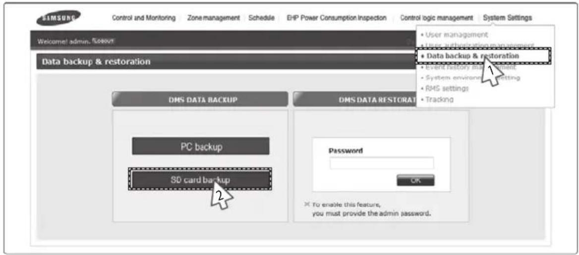
You can back up DMS2 data to a PC or SD card.
1. Click [System Settings] → [Data backup & restoration] when the DMS2 web page menu screen appears. 2. Click [SD card backup] when the DMS2 data backup & restoration screen appears.
◆ The message "Reading data from DMS2. Please wait." will be displayed. ◆ Depending on the size of the data, backup time may vary. It will usually take a few seconds.
System Settings (Continued)

3. Click [OK] when the message "DMS2 data backup completed." appears.
The created file name is as follows:
DMS2dataYYYYMMDD.dms" message appears.
◆ The file name of the backup file is "DMS2dataYYYYMMDD.dms" and it does not exceed a maximum of 15 characters. (YYYY: year, MM: month, DD: day) ◆ Backup files recorded on the same date are numbered in order of 001, 002. ◆ The extension of the backup data files is ".dms". If the "Backup failed." message appears, click [OK]. Then check if the SD card is inserted or is forbidden for writing.
Note
Backup data includes DB data, setting data, data related to indoor/outdoor unit control, and various kinds of history data. They will be backed up in a single unified file.

◆ To use the SD backup and restoration function properly, an SD card formatted in the VFAT file system is required. If an SD card is already inserted, the automatic backup function will operate and everyday data will be backed up to the SD card. If the available space on the SD card is smaller than 100 Mbytes, the process of deleting the oldest DMS2 backup file will be performed first, and then the auto backup function will operate.

DMS2 Data Restoration - PC Restore

1. Click [System Settings] → [Data backup & restoration] when the DMS2 web page menu screen appears. 2. Enter the password of the Admin account when the DMS2 data backup and restoration screen appears.
◆ The data restoration function deals with the important data of the system.
To activate the function, you should enter the administrator's password.
3. Click [OK]. 4. Click [OK] when the caution window appears.
System Settings (Continued)


5 Click [PC restore].
6 Click [Browse].
- Select DMS2 data file to restore and then click [Open(O)] when "File selection" window appears.
7 Check if the file route and file name are correctly entered in the text box, and then click [Upload].

8 Click [OK] when "Restore the DMS by using the file. Do you want to continue?" message appears.
◆ "Reading data from DMS2. Please wait." message window will appear. ◆ Depending on the size of the data, backup time may vary. It will usually take few seconds.
9 Click [OK] when "Restoration is complete. Click 'OK' to restart DMS." confirm window appears.
◆ DMS2 will restart and restored data will be reflected.
Note ◆ Backup and restoration of set event history is not available.
◆ Backup and restoration of network setting is not available.

CAUTION
Keep in mind followings when operating restoration using backup file saved in PC.
- You cannot use files bigger than 100Mbytes for restoration file.
- Restoration should be carefully executed because existing data will be deleted during restoration and the data you select will be restored. Before operating restoration, backup current data of DMS2 to PC or SD card.
- The name of file for restoration should be within 32 letters in English alphabet or numbers. If not, rename the file and upload it again.
DMS2 Data Restoration - SD Card Restoration

1 Click [System Settings] → [Data backup & restoration] when DMS2 web page menu screen appears. 2 Enter the password of Admin account when DMS2 data backup and restoration screen appears.
◆ Data restoration function deals with the important data of the system.
To activate the function, you should enter administrator's password.
3 Click [OK]. 4 Click [OK] when caution window appears.


5 Click [SD card restore]. 6 Select the check box of file to restore. 7 Click [OK].
System Settings (Continued)

8 Click [OK] when "Restore DMS data by using the file. Do you want to continue?" message appears.
◆ "Reading data from DMS2. Please wait." message window appears. ◆ Depending on the size of the data, backup time may vary. It will usually takes few seconds.
9 Click [OK] when "Restoration is complete. Click 'OK' to restart DMS." message window appears.
◆ DMS2 will restart and restored data will be reflected.
Note For proper restoration, unlock the forbidden writing function of SD card.
Event History Management "Search(Check)"

You can search(check) all kinds of set information of event log in DMS2.
1 Click [System Settings] → [Event history management] when DMS2 web page menu screen appears.
2 Select the period of event history you want to search.
3 Click [Search].
4 List of events which occurred in the period will be displayed.
- You can check detailed information about the event by selecting the item you want to check.
Note You can check following event logs using event history management.
- DMS2 power related event
- Schedule setting related event
- RMS service setting related event
- Tracking related event
- User information modification related event
- System settings related event
- Operation using external interface related event
DMS2 Network Information Setting – “Manual Setting”
You can set and check information about DMS2 installation operation.
1. Click [System Settings] → [System environment setting] when the DMS2 web page menu screen appears. 2. Click [Edit] from the DMS2 network information window. 3. When text boxes for IP address, subnet mask address, default gateway, and DNS server are enabled, enter values for each item.
◆ 15 letters can be entered for each item. ◆ Each item should match the network address form. ◆ Basically, only Private IP can be set as the IP address. To use Public IP, you must set Enable public IP as 'Enable' from the menu [System Settings] → [System environment setting].
- Private IP range: 10.0.0.0 ~ 10.255.255.255, 172.16.0.0 ~ 172.31.255.255, 192.168.0.0 ~ 192.168.255.255
- Public IP range: IP except for Private IP range and 127.0.0.1 (localhost)
4. Click [Save] in the DMS2 network information window.
5. Click [OK] when the message "This operation needs web browser restart. The browser will be closed. Do you want to proceed?" appears.
◆ Click [OK] and the current web browser will be closed. Run the web browser again and you can access DMS2 using the IP that was manually set.
DMS2 Network Information Setting – using "DHCP"

1. Click [System Settings] → [System environment setting] when the DMS2 web page menu screen appears.
2. Click [Edit] from the DMS2 network information window.
3. Check 'DHCP'.
◆ The text boxes for IP address, subnet mask address, default gateway, and DNS server will be disabled. If you want manual setting, uncheck 'DHCP' and then refer to "DMS2 Network information setting - manual setting" steps. (Refer to page 124) ◆ DMS2 supports DHCP. Only private IP should be assigned from DHCP. If Public IP is assigned from DHCP, you cannot access DMS2. If Public IP must be assigned from DHCP, you must set Enable public IP as 'Enable' from the menu [System Settings] → [System environment setting].
4. Click [Save] in the DMS2 network information window. 5. Click [OK] when the message "This operation needs web browser restart.
The browser will be closed. Do you want to proceed?" appears.
◆ Click [OK] and the current web browser will be closed. Run the web browser again and you can access DMS2 after checking the auto setting IP on the external LCD.

Some functions available on DMS2 web page may not be functional at BACnet Gateway and LonWorks Gateway. For detailed function, refer to the installation manual or contact Samsung Electronics.
System Settings (Continued)
Note ◆ Factory setting is as follows.
- IP address: 192.168.0.100
- Subnet mask address: 255.255.255.0
- Default gateway: 192.168.0.1
- DNS server: 0.0.0.0
◆ DMS2 sets service engineer IP(192.168.0.254) internally. Therefore, it should be available all the time regardless of current IP setting. ◆ DMS2 gets DHCP IP address when you activate DHCP function.
When connecting DMS2 to S-NET series, you can connect them using the IP. However the DHCP IP address can be changed by events such as network environment of restart.
In this case, it may cause communication failure between S-NET series and DMS2.
Therefore it is not recommended to connect DMS2 using DHCP address using S-NET series.
◆ You can check network information on external LCD of DMS2 when activating DHCP. (Refer to page 158) When DHCP is set, address from DHCP server will be set as DMS2 IP address. ◆ DHCP function is not available when you use BACnet Gateway function.

CAUTION
This product must be used in a dedicated network because it cannot respond to network attacks such as hacking and viruses. When it is connected to the Internet or an intranet (e.g., an office LAN), it could be at risk of illegal access. Also, this may change it to a harmful connection for other network devices. This is not the responsibility of Samsung Electronics and is not included in compensation for the damage.

System Time Setting

1. Click [System Settings] → [System environment setting] when the DMS2 web page menu screen appears. 2. Click [Edit] from system time setting. 3. Enter system time (year/month/day/hour/minute/second).
◆ You can enter only numbers. ◆ Year: You can enter from 1980 to 2035. ◆ Month: You can enter from 1 to 12. ◆ Day: You can enter from 1 to 31. ◆ Hour: You can enter from 0 to 23. ◆ Minute: You can enter from 0 to 59. ◆ Second: You can enter from 0 to 59.
4. Click [Save] after setting is completed.
System Settings (Continued)

5. Click [OK] when the "This information will be modified. Do you want to proceed?" message window appears.
6. The "Reading data from DMS2. Please wait." message appears and saving is completed. Then, the system environment setting screen appears again with all items disabled.
Note: Time on the screen shows DMS2 setting time.

Selecting the Language


1. Click [System Settings] → [System environment setting] when the DMS2 web page menu screen appears.
2. Click [Edit] from language selection.
3. Select a language you want, then click [Save].
4. Click [OK] when the "This operation needs DMS to be restarted. Do you want to apply the setting?" message appears.
◆ Click [OK] and the current web browser will be closed. DMS2 will restart and it may take approximately 1 minute.
DMS2 Name Setting

1. Click [System Settings] → [System environment setting] when the DMS2 web page menu screen appears. 2. Click [Edit] from DMS2 name setting. 3. Enter the name of DMS2 when the DMS2 name field is enabled.
- You can use a maximum of 30 letters, including English alphabets and special symbols. When the DMS2 name is set, the name will be displayed on the top title bar of the web browser.
4. Click [Save] after the setting is completed.
This information will be modified. Do you want to proceed?

5. Click [OK] when the "This information will be modified. Do you want to proceed?" message appears.
6. The "Reading data from DMS2. Please wait." message appears and saving is completed. Then, the system environment setting screen appears again with all items disabled.
- You can check the new DMS2 name on the title bar of the web browser.
Note: The name of the DMS2 is set to blank as factory default.
System Settings (Continued)

Error Mail Forwarding Setting

1. Click [System Settings] → [System environment setting] when the DMS2 web page menu screen appears. 2. Click [Edit] from error mail forwarding setting. 3. Set all the items to the value you want when all item fields are enabled.
◆ If you select 'Apply', you should input e-mail address, SMTP server ID, password, and SMTP server address. ◆ If you select 'Not apply', E-mail, ID, PW and SMTP server items will not affect the setting.
4. Click [Save] after the setting is completed.
This information will be modified. Do you want to proceed?

5 Click [OK] when "This information will be modified. Do you want to proceed?" message appears.
6 "Reading data from DMS2. Please wait." message appears and saving is completed. Then, system environment setting screen appears again with all items disabled.
Note: In factory setting, 'Not apply' is checked and item fields (E-mail, ID, PW, SMTP) are blank.
Note: E-mail forwarding function cannot deal with the server using encryption algorithm such as SSH, SSL, S/MIME. Use the function to the mail server which uses e-mail address and password based on text transmission method.
Contact Control Pattern Selection

1 Click [System Settings] → [System environment setting] when DMS2 web page menu screen appears. 2 Click [Edit] from contact point pattern selection window. 3 Select the pattern you want to check.
◆ Pattern 1 [No external input]: No operation will be made when inputting contact control signal. ◆ Pattern 2 [Level (Emergency stop)]: Commands that stop all operation of indoor unit and disable remote control when inputting contact control signal. In level emergency stop status, it will not be controlled even if the command is from upper controller. ◆ Pattern 3 [Level (Operation/Stop)]: Level signal input timing. It changes operation/stop status of all indoor units. ◆ Pattern 4 [Pulse (Operation/Stop, Disable/Enable)]: Pulse signal. It changes operation/stop status of all indoor units.
4 Click [Save] after setting is completed.
This information will be modified. Do you want to proceed?

5 Click [OK] when "This information will be modified. Do you want to proceed?" message appears.
6 "Reading data from DMS2. Please wait." message appears and saving is completed. Afterwards, system environment setting screen appears again with all items disabled.
If at least one of indoor unit is turned on, contact point output port 1 generates contact point signal.
◆ If there is breakdown, contact point output port 2 generates contact point signal.
Note: Pattern 1 is set as factory setting of contact control pattern.
◆ Contact output
- When indoor unit is in operation, DMS2 which executed tracking successfully outputs signal through DO Ch1.
- If there is unsolved breakdown in DMS2, signal will be output through DO Ch2. You can check it through check indicator on DMS2.

For extension, DMS2 has 10 DI/DO ports. Contact control and output function are assigned to Ch1 and Ch2. Ch3~Ch10 will be assigned to additional functions.
For proper contact control, connect using Ch1 and Ch2.
Setting Control and Monitoring

1 Click [System Settings] → [System environment setting] when DMS2 web page menu screen appears. 2 Click [Edit] on Control and Monitoring section. 3 Select 'Decimal point control' or 'Display the revised temp. in heat mode'.
◆ Decimal point control: Select this function if you want to control the indoor unit in 0.1°C unit. If this is not selected, temperature will be adjusted in 1°C even if the indoor unit supports decimal point control which allows temperature adjustment in 0.1°C unit. ◆ Display the revised temp. in heat mode: Select this function if you want to display the revised temperature for current temperature in heat mode.
4 Click [Save].

Setting silent control

1 Click [System Settings] → [System environment setting] when DMS2 web page menu screen appears. 2 Click [Edit] on Set silent control section. 3 Select 'Control and Monitoring' or 'Schedule' or 'Control logic'.
◆ Control and Monitoring: Select this if you want to control silently in 'Control and Monitoring' screen. ◆ Schedule: Select this if you want to perform 'Schedule' silently. ◆ Control logic: Select this if you want to perform 'Control logic' silently.
4 Click [Save].
System Settings (Continued)
Setting level control
1 Click [System Settings] → [System environment setting] when DMS2 web page menu screen appears. 2 Click [Edit] on Set level control section. 3 Select 'Include the OnOff controller'.
◆ Include OnOff controller: Select this if you want to restrict controlling from OnOff controllers when you disable RC from the DMS2.
4 Click [Save].
Setting temperature scale

1 Click [System Settings] → [System environment setting] when DMS2 web page menu screen appears. 2 Click [Edit] on the temperature scale. 3 Select the temperature display of DMS2 as Celsius or Fahrenheit. 4 Click [Save].
Setting Enable public IP
1 Click [System Settings] → [System environment setting] when DMS2 web page menu screen appears. 2 Click [Edit] on Enable public IP section. 3 Select whether to use Public IP or not. When you select 'Enable', you must register the Public IP of PCs or network devices to access DMS2 from the PCs or network devices. 4 Click [Save].
Setting Public IP of upper controller
1 Click [System Settings] → [System environment setting] when DMS2 web page menu screen appears. 2 Click [Edit] on Public IP of upper controller section. 3 Register the Public IP of PCs or network devices to access DMS2 from the PCs or network devices. ◆ Select 'Apply' after entering Public IP to access DMS2. 4 Click [Save].
RMS Service Usage Setting

1 Click [System Settings] → [RMS settings] when DMS2 web page menu screen appears. ※ RMS is a Remote Management Service of a system air conditioner 2 Click [Edit] on Service usage section to select whether or not to use the RMS.
- Select either 'Use' or 'Unuse'
When 'Use' is selected, enter the Connection ID and the License ID as instructed in step 3 and 4. When 'Use' is selected, DNS server address must be set on the DMS network information section of the [System Settings] → [System Environment setting] menu. When 'Unuse' is selected, Connection ID and the License ID setting is not necessary. (Skip to step 5)
3 Enter the Connection ID.
* Connection ID is required to classify the DMS in the RMS server.
◆ Click [Edit] and enter the Connection ID. If the connection ID was not assigned, add the DMS of the corresponding site on the RMS web page and get a connection ID.
4 Enter the License ID.
* To use the RMS service, license ID must be entered.
◆ Click [Edit] and enter the License ID.
System Settings (Continued)

5 Click [Save] when setting is complete.
◆ "You must restart DMS for the task: Do you want to proceed applying the setting?" message will appear. Click [OK], then DMS2 will restart and the changed settings will be applied.
Downloading user manual
- Click [System Settings] → [User manual] when DMS2 web page menu screen appears.
◆ You can download the user manual.
System Setting Initialization
192.168.0.100
06:12:13(AM)
- Press [Menu], [▲], [▼] or [Set] on LCD if IP and current time are displayed on LCD screen.
◆ Main menu screen appears. ◆ Initialization is not possible in the screen which time information is displayed.
MAIN MENU
1. IP Config
- Press [Menu] → [▼] → [▲] → [▼] → [Menu] buttons in order in main menu screen.
◆ Caution will be displayed on LCD Display.
Are you sure?
YES:Set, NO:Menu
- Initialize DMS2 by clicking [Set] when caution phrase appears.
◆ If you press [Menu] button, it will turn back to main menu without initialization.

CAUTION
When initializing system setting, all saved data in DMS2 will be deleted.
After initialization, saved data and IP address will be same as factory setting.
System Settings (Continued)
Tracking
What is tracking?
Tracking is an operation that finds devices which are connected to DMS2.
Through tracking operation, devices which are connected to DMS2 can recognize if they are connecting to DMS2.
To supervise and control the system air conditioner using DMS2, tracking should be done first.
◆ Things you can do through tracking
Checking the number of devices installed, setting communication mode by channel, DVM tracking, and renaming are possible through tracking.
◆ Execute tracking
(1) Connect DVM device
- Connect the device to COM1~COM5.
(2) Set communication mode by channel.
- Set the proper communication mode that fits the devices connected in step (1).
- Be careful that if the communication mode is not properly set, the device will not be found through tracking.
(3) Execute tracking - Execute DVM tracking.
- DVM tracking is an operation that finds system air conditioner devices such as indoor/outdoor units and watt-hour meters.
(4) Name setting for each device.
- Name setting for each device is a function that sets the name of connected devices. Set the name that shows the installation location of the device.
◆ Communication mode setting by channel
Roles
- It records what devices are connected to COM1~COM5 of DMS2.
- Through tracking, DMS2 searches for proper devices that fit the user's settings.
- Select the appropriate communication mode that fits the connected device.
What is communication mode?
- Outdoor units, On/Off controllers, SIM, and PIM can be connected to DMS2.
- The following is the list of devices that can be communicated through each communication mode.
- NEW mode: On/Off controllers, outdoor units, and SIM/PIM that support the new communication mode.
- IM mode: IM mode cannot be set, but it can be used for function changes or new functions with an updated version.
Communication Mode Setting by Channel

1. Click [System Settings] → [Tracking] when the DMS2 web page menu screen appears. 2. Click [Edit] from the communication mode by channel setting.
◆ [Edit] will change to [Cancel]. Selection buttons are enabled. However, the channels that have a searched device maintain their selection button disabled.
3. When each channel is enabled, check the communication mode you want to set for each channel.
- You cannot change the communication mode of a channel that currently has a connected device. When 'NEW' is set as the communication mode, the setting will allow tracking, monitoring, and controlling devices that support the NEW communication mode. ◆ IM mode cannot be set, but it can be used for function changes or new functions with an updated version.
4. Click [Save] after the setting is completed.
◆ "Reading data from DMS2. Please wait." message appears and saving is completed. Then, the tracking page with disabled items will be displayed again. ◆ If you click [Cancel], check boxes will be disabled and [Cancel] will change to [Edit].
System Settings (Continued)

DVM Tracking

1. Click [System Settings] → [Tracking] when the DMS2 web page menu screen appears. 2. Click [DVM Tracking].
When the addresses of the devices are collected, you can perform re-tracking without collecting detailed information.

Some functions available on the DMS2 web page may not be functional at the BACnet Gateway and LonWorks Gateway. For detailed functions, refer to the installation manual or contact Samsung Electronics.

When the tracking command is executed, the system configuration is initialized.
If the tracking result does not match the actual installation information, serious errors may occur in features such as power distribution.
Check if the installation information is identical to the tracking result.
Click "Cancel" to cancel tracking, or "OK" to execute tracking.

3. Enter the administrator's password and then click [OK].
4. The tracking information window pops up. Check and click [OK] to continue.
◆ Execute tracking depending on the communication mode set by communication mode setting by channel.
(1) When 'NEW' is set as the communication mode, DMS2 executes tracking on devices that support NEW communication.
5. "Tracking is in progress. Please wait." message appears.
◆ Tracking takes from tens of seconds to several ten minutes.
However, it may vary depending on the number of installed controllers.
System Settings (Continued)

6 Tracking completed message will appear.
Select Zone initialization mode you want and click [OK].
◆ Not initialize: No zone information initialization will be made. ◆ Initialize individually: Initialize zone information as individual mode. ◆ Initialize by group: Initialize zone information as group mode.
Note ◆ If tracking is executed successfully while NEW is set as communication mode for each channel, virtual OnOff controller will be assigned to each channel.
◆ If there is no searched outdoor unit, OnOff controller, SIM/PIM, it is regarded as DVM tracking failure. ◆ If there are devices which have same address, first searched device will be registered only. ◆ The number of OnOff controller doesn't contain the number of virtual OnOff controller that is used in NEW communication. ◆ Total number of indoor units includes general indoor units, ERV, AHU, MINI AHU, Fresh ducts, ERV PLUS, Hydro Unit, Hydro Unit HT and Single EHS. ◆ Group initialization will not be applied to Hydro Unit, Hydro Unit HT and Single EHS.

◆ If you execute tracking, system setting will be initialized. If tracking result does not match with actual installation information, there can be critical error in additional functions such as power distribution. ◆ Make sure that tracking information matches to actual installation information after tracking.
Disconnect All Devices
◆ Function
Initialize searched device status in DMS2. Using this function, monitoring and controlling of all the connected devices to DMS2 will be stopped.
◆ When is it needed?
- Connect searched device to the other channel and execute tracking. If the other device is searched in the channel you want to use, use 'Disconnect all devices' function.
- If you use this function, DMS2 device connection status will be initialized.

1 Click [System Settings] → [Tracking] when DMS2 web page menu screen appears. 2 Click [Disconnect all devices].
System Settings (Continued)
![graph TD A["Admin password"] --> B{OK Cancel} B -->|3| C["When disconnection command are executed, all devices are disconnected."] C --> D["The disconnection may cause serious errors in the features such as power distribution."] D --> E["Click "Cancel" to cancel disconnection, or "OK&…](/content/2026/05/947375/images/245f7a053673de24fd2f9829c7f079375aebd40c122dde5aef91bf9f10b1af93.jpg)
3. Enter the administrator's password and then click [OK]. 4. Disconnect all devices. The information window pops up. Check it and click [OK] to continue. 5. The message "Reading data from DMS2. Please wait." appears. After completing the disconnect all devices operation, the page will be refreshed.
Note: After executing the disconnect all devices function, the device search status of DMS2 will be initialized.
You should execute tracking again after using the disconnect all devices function.
Renaming the Device

1. Click [System Settings] → [Tracking] when the DMS2 web page menu screen appears.
2. Click [Edit] at the bottom of the tracking device list.
[Edit] will change to [Cancel]. When the type of the device is displayed, the new communication address will be shown with it.
System Settings (Continued)

3. Enter the device name, which is saved in the PBA of the indoor unit and outdoor unit, in the Device name field, or enter the name, which is saved in the DMS2, in the Name field.
You cannot use special symbols as Device name and Name. The Name should be within 16 letters. The Device name should be within 10 letters. Select the check box beside 'Device name' if you want to use the name of the device (that supports NEW communication) which is saved in the PBA.
4. Click [Save] after setting is completed.
The message "Reading data from DMS. Please wait." appears and saving is completed. Then, the tracking page with disabled items will be displayed again. If you click [Cancel], input fields are disabled and [Cancel] will change to [Edit].
DMS DI·DO Port Setting
1. Select [System Settings] and then click [Tracking]. 2. Click [Setting] which is next to DMS DI·DO of the device list. 3. Click [Edit] at the bottom of the DMS DI•DO setting page. [Edit] will change to [Cancel].
System Settings (Continued)
Control and Monitoring Zone management Schedule EHP Power Consumption Inspection Control logic management System Settings
Welcome admin.
The following Tracking
DMS DI/DO
DMS DI/DO 56 Setting
| Address | Port type | Device type | Shot name | Full name | MIN | MAX |
| 56.00.03 | DI | DI | 56.00.03 | OFF | ON | |
| 56.00.04 | DI | DI | 56.00.04 | OFF | ON | |
| 56.00.05 | DI | DI | 56.00.05 | OFF | ON | |
| 56.00.06 | DI | DI | 56.00.06 | OFF | ON | |
| 56.00.07 | DI | DI | 56.00.07 | OFF | ON | |
| 56.00.08 | DI | DI | 56.00.08 | OFF | ON | |
| 56.00.09 | DI | DI | 56.00.09 | OFF | ON | |
| 56.00.10 | DI | DI | 56.00.10 | OFF | ON | |
| 56.01.03 | DO | DO | 56.01.03 | OFF | ON | |
| 56.01.04 | DO | DO | 56.01.04 | OFF | ON | |
| 56.01.05 | DO | DO | 56.01.05 | OFF | ON | |
| 56.01.06 | DO | DO | 56.01.06 | OFF | ON | |
| 56.01.07 | DO | DO | 56.01.07 | OFF | ON | |
| 56.01.08 | DO | DO | 56.01.08 | OFF | ON |


4 Edit each item when DMS DI/DO selection and input fields are enabled.
◆ Device type : DI or DO ◆ Short name : Input short name of the device. ◆ Full name : Input full name of the device. ◆ Minimum value / Maximum value : MIN value is fixed as OFF and MAX value is fixed as ON.
5 Click [Save].
◆ After the saving is complete, DMS DI/DO setting page with all deactivated items will appear. ◆ If you press [Cancel], web page will refresh and it goes back to the state before the modification.

PIM Setting

1 Click [System Settings] → [Tracking] when DMS2 web page menu screen appears. 2 Click [Setting] which is next to PIM of device list. ◆ Enter administrator's password and then click [OK]. 3 Click [Edit] which is on the bottom of PIM setting page. ◆ [Edit] will change to [Cancel].
System Settings (Continued)

4 Select a field you want to change.
◆ Meter Value (0~99999.9, to one decimal place) ◆ Meter Type / Pulse rate
- Electricity (1~10000)
- Water (1~10000)
- Gas (0.001~10, to three decimal places)
◆ Channel Status ◆ Time Setting ◆ PIM Password (Number)

CAUTION
You should tick the check box of the channel you want to change.
5 Click the check boxes to select the channel applying for the setting. 6 Click [Save].
If you press [Cancel], web page will refresh and it goes back to the state before the modification.
Using LCD and LCD Button
LCD is mounted on DMS2 for installation and convenience of the user.
◆ You can search menu and change setting using [▲] and [▼] buttons. ◆ If you press and hold [▲] or [▼] button in some menu such as IP setting, the value changes faster. ◆ To go to upper menu or cancel, select [MENU] button. ◆ To go to sub menu, select or save, press [SET] button. ◆ Operates some menus with care because they are related to the proper operation of DMS2 system. ◆ If you do not use DMS2 buttons for long periods of time, set button lock to avoid malfunction. ◆ Manufacturer is not responsible for the damage caused by wrong operation.
Checking Main Menu
192.168.0.100
06:12:13(AM)
- If IP and current time are displayed on LCD display, press [Menu], [▲], [▼] or [Set] button.
◆ Main menu screen will be displayed.
- Check menu options by pressing [▲], [▼] buttons.
| 1 IP | Config Network information setting |
| 2 In | Outdoor Checking Indoor/Outdoor unit information |
| 3 DMS2 Version Checking DMS2 version | |
| 4 DMS2 Time Setting DMS2 time | |
| 5 Data Backup Setting data backup | |
| 6 Peak Level Checking peak level | |
| 7 Error Status Checking error information | |
| 8 Password Reset Password reset | |
| 9 Button Lock Button lock function | |
| 10 Safety Halt Safe end function | |
Network Information Setting (IP Config)
192.168.0.100 06:12:13(AM)
- Check main menus by pressing [Menu], [▲], [▼] or [Set] button.
MAIN MENU 1.IP Config
- Select 1.IP Config by pressing [▲] and [▼] buttons, and press [Set] button.
◆ Network setting screen will be displayed.
IP ADDRESS 192.168.0.100
- Select the item you want by pressing [▲] and [▼] buttons.
◆ You can select from IP address, subnet mask address, gateway address, and DNS server.
SET YOUR IP 192.168.0.79
- Edit selected network information by pressing [Set] button.
◆ Number to edit will blink. ◆ You can change value by pressing [▲] and [▼] buttons. To move to next number, press [Set] button. ◆ If you press and hold [▲] or [▼] button, the value changes faster. ◆ After setting all the 4-digit number, press [Set] button to save the new settings. ◆ To cancel the setting, press [Menu] button.
Auto Address Setting (DHCP CONFIG)
192.168.0.100
06:12:13(AM)
- Check main menus by pressing [Menu], [▲], [▼] or [Set] button.
MAIN MENU 1.IP Config
- Select 1.IP Config by pressing [▲] and [▼] buttons, and press [Set] button.
◆Network setting screen will be displayed.
DHCP CONFIG Current disabled
- Select auto address setting function (DHCP CONFIG) by pressing [▼] button.
◆ Auto address setting function status will be displayed. Current disabled: Auto address setting function disabled. Current enabled: Auto address setting function enabled.
Enable DHCP? YES:Set, NO:Menu
- Enable/Disable auto address setting function by pressing [Set] button.
◆ If auto address setting function enabled - You can change it to disabled status by pressing [Set] button. ◆ If auto address setting function disabled - You can change it to enabled status by pressing [Set] button. ◆ To maintain current status, press [Menu] button. ◆ DHCP function is not available when you use BACnet Gateway function.
Checking Indoor/Outdoor Unit Information
Checking Indoor/Outdoor Unit Information
192.168.0.100
06:12:13(AM)
- Check main menus by pressing [Menu], [▲], [▼] or [Set] button.
MAIN MENU
- In/ Outdoor
- Select 2.In/Outdoor by pressing [▲] and [▼] buttons.
IN/ OUTDOOR INFO
Indoor:64
- Press [Set] button.
◆ The number of indoor units connected to DMS2 will be displayed.
IN/ OUTDOOR INFO
Outdoor:6
- Check outdoor unit information by pressing [▼] button.
◆ The number of outdoor units connected to DMS2 will be displayed. ◆ To check indoor unit information again, press [▲] button. ◆ You can go back to main menu by pressing [Menu] or [Set] button.
Checking DMS2 Version
Checking DMS2 Version
192.168.0.100
06:12:13(AM)
- Check main menus by pressing [Menu], [▲], [▼] or [Set] button.
MAIN MENU
- DMS Version
- Select 3. DMS2 Version by pressing [▲] and [▼] buttons.
DMS version
2.0
- Press [Set] button.
◆ Current version of DMS2(DMS2 Version) will be displayed. ◆ You can go back to main menu by pressing [Menu] or [Set] button.
DMS2 Time Setting – Checking and Setting Date
192.168.0.100
06:12:13(AM)
- Check main menus by pressing [Menu], [▲], [▼] or [Set] button.
MAIN MENU
- DMS time
- Select 4. DMS2 Time by pressing [▲] and [▼] buttons.
◆ Current set date of DMS2 will be displayed.
CURRENT DATE
1983:04:16
- When 'CURRENT DATE' appears, set current data by pressing [Set] button.
◆ Number to edit blinks.
◆ You can change value by pressing [▲] and [▼] buttons. To move to the next number, press [Set] button.
◆ Press and hold [▲], [▼] buttons to change the number continuously.
◆ Set year, month and day in order, and then press [Set] button to save.
◆ To cancel the setting, press [Menu] button.
DMS2 Time Setting – Checking and Setting Time
192.168.0.100
06:12:13(AM)
- Check main menus by pressing [Menu], [▲], [▼] or [Set] button.
MAIN MENU
- DMS time
- Select 4. DMS2 Time by pressing [▲] and [▼] buttons.
◆Current set time of DMS2 will be displayed.
CURRENT TIME
16:46:37(PM)
- Select 'CURRENT TIME' by pressing the [▼] button. Then set the time by pressing the [Set] button.
◆ The current set time of DMS2 will be displayed. ◆ The number to edit blinks. ◆ You can change the value by pressing the [▲] and [▼] buttons. To move to the next number, press the [Set] button. ◆ Press and hold the [▲] and [▼] buttons to change the number continuously. ◆ Set hour, minute, and second in order, then press the [Set] button to save. ◆ To cancel the setting, press the [Menu] button.
Data Backup Setting
Data Backup
192.168.0.100
06:12:13 (AM)
- Check the main menus by pressing the [Menu], [▲], [▼], or [Set] button.
MAIN MENU
5. Data Backup
- Select 5. Data Backup by pressing the [▲] and [▼] buttons.
◆ The DMS BACKUP MENU will appear.
DMS BACKUP MENU - Data Backup
- Check if Data Backup is selected. Then press the [Set] button.
◆ You can start the backup by pressing the [Set] button again. ◆ If the data backup is completed successfully, the screen below will be displayed.
Backup Completed
◆ To cancel backup, press [Menu] button.
Are you sure?
YES:Set, NO:Menu

CAUTION
◆ Before executing data backup, check if SD card is inserted. ◆ Unlock forbidding writing tab of SD card.
Data Restore
192.168.0.100
06:12:13(AM)
- Check main menus by pressing [Menu], [▲], [▼] or [Set] button.
MAIN MENU
5. Data Backup
- Select 5.Data Backup by pressing [▲] and [▼] buttons, and then press [Set] button.
◆ DMS BACKUP MENU will appear.
DMS BACKUP MENU data restore
- Check if data restore is selected by pressing [▲] button. Then select a file you want to restore by pressing [▲] and [▼] buttons.
◆ Before executing data restore, check if the SD card is inserted.
Filename:
20090725.dms
- Start data restore by pressing the [Set] button.
◆ To cancel restoration, press the [Menu] button.

When controlling DMS2 using the panel, data restore is only possible with an SD card. You can execute PC restoration through a web browser.
◆ Unlock the write-protect tab on the SD card.
Checking Error Information
Checking Error Information
192.168.0.100
06:12:13(AM)
- Check main menus by pressing the [Menu], [▲], [▼], or [Set] button.
MAIN MENU
- Error Status
- Select 7. Error Status by pressing [▲] and [▼] buttons, and then press [Set] button.
◆ Unsolved error info will be displayed.
ERROR INFO > CAU-01 611
- You can check the other error information by pressing [▲] and [▼] buttons.
◆ You can check the next error information by pressing [▼]. To check the previous error, press [▲] button.
Reset Password
192.168.0.100
06:12:13(AM)
- Check main menus by pressing [Menu], [▲], [▼] or [Set] button.
MAIN MENU
- Password Reset
- Select 8. Password Reset by pressing [▲] and [▼] buttons, and then press [Set] button.
RESET PASSWORD
WAITING......
- When "RESET PASSWORD WAITING......" message appears, press [Menu] and [Set] buttons at the same time.
◆ Button lock function will be released and confirm message for password initialization will appear. ◆ If there is no button input for around 3 seconds, password reset will be failed and it will return to main menu.
Are you sure?
YES:Set, NO:Menu
- Reset password by pressing [Set] button.
◆ Password will be reset as factory setting. (ac0530) ◆ To cancel reset password, press [Menu] button.
Note
◆ If you reset the password while you are accessed to the DMS2 web page, you must close the browser and then re-login in order to use resetted password.
Button Lock
Button Lock
192.168.0.100 06:12:13(AM)
- Check main menus by pressing [Menu], [▲], [▼] or [Set] button.
MAIN MENU 9. Button Lock
- Select 9. Button Lock by pressing [▲] and [▼] buttons.
Are you sure? YES: Set, NO: Menu
- Press [Set] button.
◆ Confirm message will appear.
BUTTON LOCKED 07:30:21 (AM)
- Press [Set] button.
◆ LCD operating button will be locked. ◆ To cancel button lock, press [Menu] button.
- To release button lock function, press [Menu] and [Set] button at the same time for 5 seconds.
Safety Halt
192.168.0.100
06:12:13 (AM)
- Check main menus by pressing [Menu], [▲], [▼] or [Set] button.
MAIN MENU
- Safety Halt
- Select 10. Safety Halt by pressing [▲] and [▼] buttons.
Are you sure?
YES:Set, NO:Menu
- Press [Set] button.
◆ Confirm message will appear.
Now sleeping..
See you again
- Press [Set] button.
◆ All functions of DMS2 will stop and 'Now Sleeping...' phrase will appear.
Note
◆ Safety halt function is an operation that saves data of DMS2 and then stops service safely. Use this function when relocation and system restart are needed. This function will not transfer DMS2 power to OFF status. Therefore, when the screen above appears, press [RESET] button on the bottom of DMS2 or remove power cable. If you do not press [RESET] button or remove power after 10 minutes passed, DMS2 will restart automatically.
Troubleshooting
| Problem Check | Solution | ____ |
| DMS2 is not working. Is there an electricity failure? Check if the power is connected to the other interface module besides OnOff controller.Then try again. | ||
| Are the adapter and power cable connected? | Check the connection of adapter and power cable. Then try again. | |
| Access to web page is not available. | Is Microsoft Silverlight installed? | Check the installation status.Refer to Start → Control Panel → Add/Remove Programs. |
| Is Microsoft Silverlight installed properly? | Microsoft Silverlight 2.0 or later version should be installed to access web page. | |
| Access to web page from outside is not available. | Are the network settings set? Contact network manager first. | |
| Isn't the fire wall set? | ||
| Power distribution is not executed properly. | Isn't the power of DMS2 disconnected? | To use power distribution function properly,the power of DMS2 should be connected all the time. |
| I forgot DMS2 IP. Press | [Menu] button from the main menu and "1. IP Config" will appear.Then press [Set] button. | The factory setting of DMS2 IP address is 192.168.0.100 |
| Indoor unit turned on or off automatically. | Isn't the schedule control in operation? | Depending on the schedule control, indoor unit can be turned on or off automatically.It is normal operation. |
| Is DMS2 system time different from current time? | Set the DMS2 system time according to current time. | |
| DI(Digital Input) external contact point function is not working. | Is the external circuit constituted? | Check if the external circuit is constituted. |
| If the contact control pattern of DMS2 set to 1? | Set the pattern which fits to the control pattern you want. | |
| Tracking is not working. | Does it show 'Tracking Fail' and is there no indoor unit? | It means tracking failure.Execute tracking again. |
Specifications
| Items Description | ||
| Exterior |  | |
| Size 240 X 255 X 64.8 mm (Width X Length X Height) | ||
| Weight 1.48 Kg | ||
| Power | Source DC ADAPTOR | |
| INPUT Voltage 100-240V 50/60Hz 1.0A | ||
| OUTPUT Voltage 12V 3A | ||
| Interface | RS-485 5 Channels | |
| Ethernet 10/100Mbps 1 Port | ||
| SD CARD Option (Purchase SD card separately) | ||
| DI 12V Digital Input 10 Channels | ||
| DO 12V Digital Output 10 Channels | ||
| Etc. Serial Port, Reset Button | ||
| Display 16-Character X 2-Line Character LCD | ||
| Input method Menu/Up/Down/Set 4-Tact Button | ||
License
Open Source Announcement
Open Source Announcement
The software included in this product contains open source software. You may obtain the complete corresponding source code for a period of three years after the last shipment of this product by sending an email to mailto:oss.request@samsung.com.
It is also possible to obtain the complete corresponding source code in a physical medium such as a CD-ROM; a minimal charge will be required.
The following URL http://opensource.samsung.com/opensource/DMS2/seq/0 leads to the download page of the source code made available and open source license information as related to this product. This offer is valid to anyone in receipt of this information.

Memo
SAMSUNG


- AIR CONDITIONER USER MANUAL
- SAFETY PRECAUTIONS
- ENGLISH
- WARNING
- CAUTION
- INTRODUCTION OF DMS2 (DATA MANAGEMENT SERVER2)
- ADVANTAGES OF DMS2 SYSTEM
- NOTE
- TERMS
- VIEWING THE PARTS
- FRONT VIEW
- INDICATOR
- BOTTOM VIEW
- SYSTEM CONFIGURATION
- CONNECTING OUTDOOR UNIT AND DMS
- WEB BROWSER SPECIFICATION
- COMPUTER SETTINGS FOR DMS2 CONNECTION
- INTERFACE WITH UPPER LEVEL CONTROLLER
- SAVE TROUBLE HISTORY
- SET AND RUN SCHEDULE
- MAIN FUNCTION (CONTINUED)
- SAVE INTEGRATED POWER DISTRIBUTION DATA
- SYSTEM ARCHITECTURE
- TIME SEGMENTATION
- STARTING DMS
- CURRENT TIME SETTING
- CONNECTING ONOFF CONTROLLER & OUTDOOR UNIT
- CONNECTING DEVICES
- ACCESS TO DMS2 & LOGIN
- LOGGED-IN USER WITH NO AUTHORIZATION
- MONITORING INDOOR UNIT OPERATION STATUS
- CONTROL AND MONITORING (CONTINUED)
- CONTROLLING AN INDOOR UNIT
- SELECT THE AIR FLOW
- SET REMOTE CONTROLLER SETTINGS
- SELECT SPI SETTING
- SELECT MDS SETTING
- SET COOLING/HEATING DISCHARGE TEMPERATURE BY CLICKING [▲] AND [▼]
- SELECT [CONTROL DISCHARGE TEMP]
- NOTE: WHEN FILTER WARNING SIGN IS DISPLAYED ON INDOOR UNIT STATUS WINDOW
- INDOOR UNIT OPERATION MODE LIMIT
- SETTING LOWER/UPPER TEMPERATURE LIMIT OF AN INDOOR UNIT
- MONITORING FRESH DUCT OPERATION STATUS
- CONTROLLING A FRESH DUCT
- MONITORING MINI AHU
- CONTROLLING MINI AHU
- SELECT OUT COOL SETTING
- SELECT OA INTAKE SETTING
- SELECT CONTROL DISCHARGE TEMP
- MONITORING ERV OPERATION STATUS
- CONTROLLING ERV
- YOU CAN MONITOR THE OPERATION STATUS OF THE ERV AND CONTROL IT AS A WHOLE OR AS INDIVIDUAL UNITS
- SELECT THE OPERATION MODE
- SELECT THE FAN SPEED
- NOTE: WHEN THE FILTER WARNING SIGN IS DISPLAYED ON THE ERV STATUS WINDOW
- MONITORING ERV PLUS OPERATION STATUS
- CONTROLLING ERV PLUS
- CONTROLLING HYDRO UNIT
- CONTROLLING HYDRO UNIT HT
- CONTROLLING SINGLE EHS
- MONITORING DMS DI/DO OPERATION STATUS
- CONTROLLING DMS DO
- MONITORING THE SELECTED MULTIPLE DEVICES OPERATION STATUS
- CONTROLLING THE SELECTED MULTIPLE DEVICES
- SELECT THE ERV OPERATION MODE
- WHEN CONTROLLING CERTAIN TYPES OF DEVICES IN DETAIL, SELECT THE DEVICE YOU WANT TO CONTROL FROM THE LIST OF THE 'SELECTED DEVICE
- CHECKING THE INSTALLATION INFORMATION
- YOU CAN CHECK THE INSTALLATION STATUS OF CURRENTLY CONNECTED DEVICE
- CYCLE MONITORING
- YOU CAN SELECT AN INDOOR UNIT AND CHECK CYCLE INFORMATION
- INDOOR UNIT USAGE RESTRICTION / OPERATION LIMIT
- SET THE CONTROL MODE
- INDOOR UNIT USAGE RESTRICTION - TEMPERATURE LIMIT IN COOL/HEAT MODE
- YOU CAN SET TEMPERATURE LOWER/UPPER TEMPERATURE LIMIT IN COOL/HEAT MODE
- CHECKING THE TROUBLE HISTORY
- CHECKING THE TROUBLE HISTORY BY DATE
- DELETING THE TROUBLE HISTORY
- OUTDOOR UNIT CONTROL
- CONTROL FOR UNOCCUPIED ROOM
- CHECKING THE OPERATION STATUS
- YOU CAN CHECK OPERATION STATUS OF INDOOR UNIT WHICH IS CONTROLLED BY DMS
- ZONE SETTING & EDIT – INDIVIDUAL/GROUP INITIALIZATION
- ZONE SETTING & EDIT – SETTING THE USER AUTHORIZATION
- ZONE SETTING & EDIT – ZONE EDIT
- ZONE MANAGEMENT (CONTINUED)
- SCHEDULE (CONTINUED)
- CLICK [SAVE]
- CREATING NEW SCHEDULE FOR EHS
- EDITING SCHEDULE
- DELETING SCHEDULE
- APPLYING SCHEDULE
- CHECKING SCHEDULE CONTROL HISTORY
- CHECKING INSPECTION RESULT (WITH SIM/PIM)
- CHECKING INSPECTION RESULT (WITHOUT SIM/PIM)
- EHP POWER CONSUMPTION INSPECTION (CONTINUED)
- SETTING THE INSPECTION SECTION
- SETTING AND CHECKING THE METER
- THE METER HISTORY
- SETTING AND CHECKING VIRTUAL CHANNEL
- CHANNEL SETTING BY INDOOR UNIT
- CHECKING INDOOR UNIT OPERATION TIME
- CONTROL LOGIC MANAGEMENT
- SETTING CONTROL LOGIC
- CONTROL LOGIC MANAGEMENT (CONTINUED)
- CLICK 'SELECT
- SELECT THE DEVICE TO USE AS FACTOR
- TO ADD OUTPUT, CLICK [ADD]
- EDITING/DELETING/COPYING CONTROL LOGIC
- ENABLE/DISABLE CONTROL LOGIC
- CHECKING CONTROL HISTORY
- ADDING A USER
- EDITING A USER
- DELETING A USER
- EDITING USER AUTHORIZATION
- INITIALIZING A USER AUTHORIZATION
- DMS2 DATA BACKUP – PC BACKUP
- YOU CAN BACK UP DMS2 DATA TO A PC OR SD CARD
- SYSTEM SETTINGS (CONTINUED)
- DMS2 DATA BACKUP – SD CARD BACKUP
- DMS2 DATA RESTORATION - PC RESTORE
- DMS2 DATA RESTORATION - SD CARD RESTORATION
- EVENT HISTORY MANAGEMENT "SEARCH(CHECK)
- YOU CAN SEARCH(CHECK) ALL KINDS OF SET INFORMATION OF EVENT LOG IN DMS
- YOU CAN SET AND CHECK INFORMATION ABOUT DMS2 INSTALLATION OPERATION
- DMS2 NETWORK INFORMATION SETTING – USING "DHCP
- SYSTEM TIME SETTING
- SELECTING THE LANGUAGE
- DMS2 NAME SETTING
- ERROR MAIL FORWARDING SETTING
- CONTACT CONTROL PATTERN SELECTION
- SETTING CONTROL AND MONITORING
- SETTING SILENT CONTROL
- SETTING TEMPERATURE SCALE
- SETTING ENABLE PUBLIC IP
- SETTING PUBLIC IP OF UPPER CONTROLLER
- RMS SERVICE USAGE SETTING
- DOWNLOADING USER MANUAL
- SYSTEM SETTING INITIALIZATION
- TRACKING
- WHAT IS TRACKING
- ◆ THINGS YOU CAN DO THROUGH TRACKING
- ◆ EXECUTE TRACKING
- ◆ COMMUNICATION MODE SETTING BY CHANNEL
- COMMUNICATION MODE SETTING BY CHANNEL
- DVM TRACKING
- DISCONNECT ALL DEVICES
- ◆ FUNCTION
- ◆ WHEN IS IT NEEDED
- RENAMING THE DEVICE
- PIM SETTING
- YOU SHOULD TICK THE CHECK BOX OF THE CHANNEL YOU WANT TO CHANGE
- USING LCD AND LCD BUTTON
- CHECKING MAIN MENU
- NETWORK INFORMATION SETTING (IP CONFIG)
- AUTO ADDRESS SETTING (DHCP CONFIG)
- MAIN MENU 1.IP CONFIG
- DHCP CONFIG CURRENT DISABLED
- ENABLE DHCP? YES:SET, NO:MENU
- CHECKING INDOOR/OUTDOOR UNIT INFORMATION
- CHECKING DMS2 VERSION
- DMS2 TIME SETTING – CHECKING AND SETTING DATE
- DMS2 TIME SETTING – CHECKING AND SETTING TIME
- DATA BACKUP SETTING
- DATA BACKUP
- MAIN MENU
- DMS BACKUP MENU - DATA BACKUP
- ARE YOU SURE
- YES:SET, NO:MENU
- DATA RESTORE
- DMS BACKUP MENU DATA RESTORE
- FILENAME
- DMS
- CHECKING ERROR INFORMATION
- RESET PASSWORD
- BUTTON LOCK
- SAFETY HALT
- TROUBLESHOOTING
- SPECIFICATIONS
- LICENSE
- OPEN SOURCE ANNOUNCEMENT
- MEMO
- SAMSUNG
Brand : SAMSUNG
Model : MIM-B17N
Category : Air conditioner