
MV1000/1 - Receiver JL Audio - Free user manual and instructions
Find the device manual for free MV1000/1 JL Audio in PDF.


| Product Type | Monoblock Class D Amplifier |
| Amplifier Class | Class D |
| RMS Power (14.4V, 4 ohms) | 1000 W |
| RMS Power (14.4V, 2 ohms) | 1000 W |
| RMS Power (14.4V, 1 ohm) | 1000 W |
| Frequency Response | 20 Hz - 200 Hz |
| Total Harmonic Distortion (THD) | < 1% |
| Input Sensitivity | 200 mV - 4 V |
| Signal-to-Noise Ratio | > 100 dB |
| Low-Pass Filter | 40 Hz - 200 Hz, variable |
| Subsonic Filter | 25 Hz, fixed |
| Bass Boost | 0 - 18 dB at 45 Hz |
| Remote Level Control | Included |
| Input Connections | 1 pair RCA |
| Output Connections | Speaker wire terminals |
| Power Supply | 12 V DC, 150 A fuse |
| Dimensions (L x W x H) | 13.0" x 7.0" x 2.1" |
| Weight | 4.5 lbs |
| Maintenance | Wipe with dry cloth |
| Safety Features | Short circuit, thermal, and overcurrent protection |
Frequently Asked Questions - MV1000/1 JL Audio
User questions about MV1000/1 JL Audio
0 question about this device. Answer the ones you know or ask your own.
Ask a new question about this device
Download the instructions for your Receiver in PDF format for free! Find your manual MV1000/1 - JL Audio and take your electronic device back in hand. On this page are published all the documents necessary for the use of your device. MV1000/1 by JL Audio.
USER MANUAL MV1000/1 JL Audio
natural_image
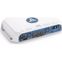
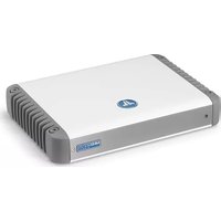
Front view of a white electronic device with a circular logo and indicator lights (no readable text or symbols)CONNECTION GUIDE
Thank you for purchasing a JL Audio amplifier for your marine sound system.
Your amplifier has been designed and manufactured to exacting standards in order to ensure years of musical enjoyment in your vessel. For maximum performance, we highly recommend that you have your new amplifier installed by an authorized JL Audio dealer. Your authorized dealer has the training, expertise and installation equipment to ensure optimum performance from this product. Should you decide to install the amplifier yourself, please take the time to read this manual thoroughly to familiarize yourself with its installation requirements and setup procedures.
If you have any questions regarding the instructions in this manual or any aspect of your amplifier's operation, please contact your authorized JL Audio dealer for assistance. If you need further assistance, please contact the JL Audio Technical Support Department at technical@jlaudio.com/support.
Installation Applications
This amplifier is designed for operation with 12 volt DC, negative-ground electrical systems. Using this product in vessels with positive ground and/or voltages other than 12V DC may result in damage to the product and will void the warranty. This product is not certified or approved for use in aircraft.
Planning Your Installation
It is important that you take the time to read this manual thoroughly and that you plan your installation carefully. It is very easy to damage electrical systems in modern vessels. Never assume that you have found appropriate wires without consulting a reliable wiring diagram or without analyzing using proper test equipment. If you are uncomfortable or unfamiliar with diagrams or testing methods, please enlist the services of your authorized JL Audio dealer to perform the installation. Your authorized dealer has the training, expertise and installation equipment to ensure optimum performance from this product. The following are some considerations that you must take into account when planning your installation.
Safety Considerations
• Install your amplifier in a dry, well-ventilated location that does not interfere with factory installed systems.
- This product should never be submerged under water or subjected to high pressure water spray.
- Do not install where it will be directly exposed to the elements, or in the engine compartment, or in any areas of extreme heat. Areas exposed to a heater or hot air should also be avoided.
- When selecting a mounting location, consider the orientation of the amplifier and its associated connection. If possible, position the amplifier vertically, with all connections pointing downward. Wiring and cables should be routed to direct potential condensation and moisture away from the amplifier.
- Securely mount the amplifier so that it does not come loose in the event of a collision or sudden jolt, or as a result of repeated vibrations during normal operation.
- Check before drilling to make sure that you will not be drilling into an exterior panel/hull, fuel tank, fuel line, wiring harness, or other vital system.
- Do not run system wiring outside or underneath the vessel. This is an extremely dangerous practice, which can result in severe damage/injury.
- Protect all system wires from sharp edges by carefully routing them, tying them down and using grommets and loom, where appropriate.
- Secure all wiring as needed, using cable ties or wire clamps to protect them from moving parts and sharp edges.

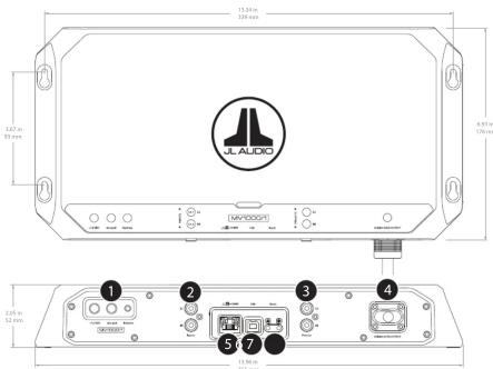
Power Connector
The MV1000/1's "+12 VDC" and "Ground" connections are designed to accept up to 2 AWG copper wire. Note: Copper Clad Aluminum (CCA) wire is not recommended. Tinned copper power wire is the best choice for marine installations. 4 AWG is the minimum copper wire size for this amplifier.
To connect the power, ground and remote turn-on wires to the amplifier, back out the set screws on the connector using the supplied hex wrenches. Strip back 3/8 inch (10 mm) of insulation from the end of each wire and insert the bare wire into the receptacle on the power connector plug, seating it firmly so that no bare wire is exposed. While holding each wire in place, tighten each set screw firmly, taking care not to strip the head of the screw. Install the power connector by plugging it into the amplifier's power connector receptacle, pushing firmly.
A. +12 VDC: Run copper wire from the positive (+12V) battery post to the amplifier mounting location. If additional amplifiers are being installed, run the appropriate gauge copper wire for the combined, maximum current draw, and install a fused distribution block near the amplifiers.
8. An appropriate fuse or ignition-protected circuit breaker (sold separately) at the main power wire(s) is vital for vessel safety. This must be installed within 7 inches (18 cm) of the battery post connection or in compliance with marine industry standards. If this is the only device connected to this main wire, use a 80 A value. Do not install the fuse or close the circuit breaker until the power wire has been securely connected to the amplifier and all other connections have been made.
C. Ground: This connection should be made to the NEGATIVE battery post. Alternatively, an appropriately equipped and positioned DC ground bus bar near the battery may be used. All ground connections (source unit and amplifiers) should be made at the same location.
D. Remote: This connection should be made to the source unit's positive (+12V) remote turn-on output. If your source unit does not have a dedicated remote turn-on output, the amplifier's remote turn-on connection can be connected to +12V via a switch that derives power from an ignition-switched circuit.

Input Section
Two female RCA jacks feed a differential-balanced input section, providing a high degree of input flexibility, and retaining superior noise rejection. This type of input architecture also allows the MV1000/1 to cleanly accept any analog audio signal up to 8 VRMS, without using a line-output converter.

Pre-Outs
Two female, RCA jacks deliver line-level, analog audio outputs (Max 4 V RMS) that are compatible with most types of aftermarket equipment.
Product Description
The MV1000/1 is a monoblock, Class D marine subwoofer amplifier equipped with NexD2 ™ , the second generation of JL Audio's high-speed switching technology. It is engineered to deliver reference-grade, low-frequency amplification with outstanding efficiency. This amplifier is configured using an external device (PC, Tablet or Phone), with the appropriate JL Audio TüN ™ application installed. (See What is TüN? section for more info.)
What is Included
(1) Amplifier (4) Mounting Screws
(1) Power Connector (1) 2.5 mm Hex Wrench (1) Subwoofer Output Harness (1) 3 mm Hex Wrench (1) USB A/B Cable (6 ft./1.8 m) (1) Connection Guide
Cooling Efficiency Considerations
The outer shell of your JL Audio amplifier is designed to remove heat from the amplifier circuitry. For optimum cooling performance, this outer shell should be exposed to as large a volume of air as possible. Enclosing the amplifier in a small, poorly ventilated chamber can lead to excessive heat build-up and degraded performance. If an Installation calls for an enclosure around the amplifier, we recommend that this enclosure be ventilated with the aid of a fan. In normal applications, fan-cooling is not necessary. When mounting the amplifier in an enclosed compartment, make sure there is at least 1 inch (2.5 cm) of space above the amplifier's outer shell to permit proper cooling.
Mounting Considerations
MV amplifiers are equipped with keyhole style mounting holes to simplify installations in confined spaces or vertical-mount applications. Mounting screws may be preinstalled, allowing amplifier connections to be made prior to securing in its final location. See diagram at right.
When selecting the installation location, consider the mounting orientation of the amplifier and its associated connections. If possible, position the amplifier vertically, with all connections pointing downward. Wiring and cables should be routed to direct potential condensation and moisture away from the amplifier. When installed in this manner, the amplifier achieves an IPX2 water-resistance rating.


Speaker Output Harnesses
Connect the speaker output leads to the corresponding speaker wires. The harness and companion cable are equipped with water-resistant connectors for maximum connection integrity in marine environments.

JLid-COMM
Connect optional accessories (MVI-HUB, M-DRC-50, VXI-BTC, etc.) to this port.

This USB A/B port permits connection to a computer for configuration and tuning, using TüN™ Software.

Reset Buttons
Use a small pin to perform the following:
(A) Factory Reset (wipe memory, reboot amp) - Press and hold the button for 7 seconds. All user settings will be erased and the amplifier will revert to its factory settings!
(B) Reboot Amplifier - Press and release the button. Previous user settings will be retained.
LED Status/Condition Reporting
LEDs located on the chassis top and connection panel are used to communicate amplifier status and condition. Refer to the table below for the location and meaning for each behavior.
| LED / Location Behavior Status/ Condition: | ||
| LED / Amplifier Top | Flashing Blue | Critical Voltage (too low) |
| Flashing Red | Critical Temperature (too hot) | |
| Flashing Yellow | Excessive Output Current (low impedance/short) | |
| Upper Left LED / Juld-COMM Port | Green | Detecting JL6® Device |
| Blue | JL6® Connection Success | |
| Yellow | Invalid JL6® Device | |
| Flashing Red | Excessive Current on Juld Port | |
| Upper Right LED / Juld-COMM Port | Flashing Red | Critical Voltage/Temperature |
| Excessive Remote Output Current | ||
| Green | Active Connection with TUN® software | |
Wiring Diagram - MV1000/1
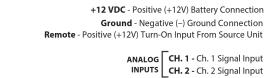
JLid-COMM - Optional Digital Remote Controller, Network Hub or Bluetooth® Communicator Connection (Sold Separately)
USB A/B Cable - To Computer with TüNTM software installed

Connections
| Power Connector | ||
| Connection With Capacity Description | ||
| +12 VDC (+) 2 AWG Positive (+) | V2 Battery Connection | |
| Ground (-) 2 AWG Negative (ND) | V3 Battery Connection | |
| Remote 18 (-) 10 AWG Positive (+) (+) | Remote Turn-On Input from Source Unit | |
| Input Section | ||
| Label RCA | Not Description | |
| CK: 1 Black RCA Channel 1 Signal Input | ||
| CK: 2 Red RCA Channel 2 Signal Input | ||
| Pre-Outs (pass-through) | ||
| Label RCA | Not Description | |
| P. 1 | Black RCA | Preamp Signal Output 1 |
| P. 2 | Red RCA Preamp Signal Output 2 | |
Connections

Specifications
| Amplifier Specifications | ||||
| Amplifier Topology | 2nd-Gen NextTM High Speed Class D | |||
| Power Supply Type | Unregulated MOSFET Switching | |||
| Operating Voltage | 10 - 15V DC | |||
| Min. Copper Power/GND Wire | 4 AWG | |||
| Recommended Fuse | 80 A | |||
| Standby Current Draw | 3.6 mA | |||
| Rated RMS Power @ 14.4V <7Hz TWD In | 600W x 1 @ 4Ω | 800W x 1 @ 3Ω | 1000W x 1 @ 2Ω | |
| Rated RMS Power @ 12.5V <7Hz TWD In | 500W x 1 @ 4Ω | 650W x 1 @ 3Ω | 800W x 1 @ 2Ω | |
| Frequency Response | 12 Hz - 300 Hz (≥0, -1dB) | |||
| Damping Factor | >400 / 50 Hz @ 4 ΣL - 300/ ± 50 Hz @ 2 Σ | |||
| IP Rating | IP(2x) when mounted vertically with connections pointed downward | |||
| Inputs/Outputs | ||||
| Analog Power/Resistor | Type | Line-Level, Differential Balanced | ||
| Number of Channels | 2, via chassis-mounted female RCA jacks | |||
| Input Voltage Range | -50 mV -8 V RMS | |||
| S/N Ratio, (A-weighted, 20 kHz noise bandwidth) | 87 dB (Reiterated to rated power), 60 dB (Reiterated to I W) | |||
| Type | Line-Level, via chassis-mounted female RCA jacks | |||
| Max Output Level | 4 V RMS | |||
| Dimensions | ||||
| L x W x H | 13.96 in ± 6.93 in ± 2.05 in / 355 mm ± 176 mm ± 52 mm | |||
TÜN.
SOFTWARE
What is TüN?
TüNTM is software that you use to setup your MV amplifier, as well as tune and configure MVi amplifiers, and other JL Audio DSP products. TüNTM automatically recognizes what it is connected to, and allows you to make adjustments with a clear interface specifically set up for that product. TüNTM is available for download for free in a variety of applications, for computers and most handheld devices. For more information, visit: jlaudio.com/tun

TÖN.
For Windows® PC or Mac® computers, TüNTM connects via USB and offers complete control and command of the entire MV and MVi feature set from the comfort of your desk or driver's seat. Software also runs in demo mode, without connected amplifiers, for offline setup or demo purposes. Test drive it for free!

TöN. | Mobile
For iPad or Android tablets. Enjoy the TüN™ software experience on your tablet, with the freedom of a wireless connection via Bluetooth®. Requires VXI-BTC Bluetooth® Communicator.

TöN. | Express
Wireless connection and streamlined options, for fast and simple amplifier setup. Download TüN™ Express for iPhone, iPad and Android phones & tablets. Requires VXI-BTC Bluetooth® Communicator.
Limited Warranty – Marine Amplifiers (USA)
JL Audio warrants this product to be free of defects in materials and workmanship for a period of two (2) years from the original date of purchase. This warranty is not transferable and applies only to the original purchaser from an authorized JL Audio dealer. Should service be necessary under this warranty for any reason due to manufacturing defect or malfunction, JL Audio will (at its discretion), repair or replace the defective product with new or remanufactured product at no charge. Damage caused by the following is not covered under warranty: accident, misuse, abuse, product modification or neglect, failure to follow installation instructions, unauthorized alteration of the material of the sale of the property shall not be required. The warranty does not cover incidental or consequential damages and does not cover the cost of removing or reinstalling the unit(s). Cosmetic damage due to accident or normal wear and tear is not covered under warranty.
Products installed as original equipment by boat manufacturers are covered by the boat manufacturer's warranty, not JL Audio, Inc.
Warranty is void if the product's serial number has been removed or defaced.
Any applicable implied warranties are limited in duration to the period of the express warranty as provided herein beginning with the date of the original purchase at retail, and no warranties, whether express or implied, shall apply to this product thereafter. Some states do not allow limitations on implied warranties, therefore these exclusions may not apply to you. This warranty gives you specific legal rights, and you may also have other rights, which vary from state to state.
If you need service on your JL AUDIO product:
All warranty returns should be sent to JL Audio's Amplifier Service Facility freight-prepaid through an authorized JL Audio dealer and must be accompanied by proof of purchase (a copy of the original sales receipt). Direct returns from consumers or non-authorized dealers will be refused unless specifically authorized by JL Audio with a valid return authorization number. Warranty expiration on products returned without proof of purchase will be determined from the manufacturing date code. Coverage may be invalidated as this date is previous to purchase date. Non-defective items received will be returned freight-collect. Customer is responsible for shipping charges and insurance in sending the product to JL Audio. Freight damage on returns is not covered under warranty.
For Service Information in the U.S.A. please call
L Audio Customer Service:
(954) 443-1100 9:00 AM - 5:30 PM (Eastern Time Zone)
JL Audio, Inc.
10369 North Commerce Pkwy. Miramar, FL 33025
(Do not send product for repair to this address)
International Warranties:
Products purchased outside the United States of America are covered only
by that country's distributor and not by JL Audio, Inc
MV1000/1_MAN_071519

- Installation Applications
- Planning Your Installation
- Safety Considerations
- Power Connector
- Input Section
- Pre-Outs
- Product Description
- What is Included
- Cooling Efficiency Considerations
- Mounting Considerations
- Speaker Output Harnesses
- JLid-COMM
- Reset Buttons
- LED Status/Condition Reporting
- TÜN.
- SOFTWARE
- What is TüN?
- TÖN.
- TöN. | Mobile
- TöN. | Express
- Limited Warranty – Marine Amplifiers (USA)
- Warranty is void if the product's serial number has been removed or defaced.
- If you need service on your JL AUDIO product:
- For Service Information in the U.S.A. please call
- L Audio Customer Service:
- JL Audio, Inc.
- International Warranties:
Brand : JL Audio
Model : MV1000/1
Category : Receiver