
RGX7500 - Generator SUBARU - Free user manual and instructions
Find the device manual for free RGX7500 SUBARU in PDF.


| Product Type | Generator |
| Brand | Subaru |
| Model | RGX7500 |
| Generator Type | Brush, self-exciting, 2-poles, single phase |
| Engine Type | Subaru EX40D, air-cooled, 4-stroke, OHC, gasoline |
| Displacement | 404 mL (24.65 cu.in) |
| AC Rated Output | 6000 VA (6000 W) |
| AC Voltage | 120/240 V |
| AC Frequency | 60 Hz |
| AC Rated Current | 50/25 A |
| DC Output | 12 V, 8.3 A (100 W) |
| Starting System | Electric starter / Recoil |
| Fuel Type | Automotive unleaded gasoline |
| Fuel Tank Capacity | 22.0 L (5.8 U.S. gal) |
| Oil Capacity | 1.2 L (0.32 U.S. gal) |
| Dimensions (L x W x H) | 710 x 545 x 595 mm (28.0 x 21.5 x 23.4 in) |
| Dry Weight | 96.5 kg (212.8 lb) with electric starter |
| Spark Plug | BR-6HS (NGK) |
| Key Features | GFCI receptacle, Full Power Switch, Idle Control, Oil Sensor, Spark Arrester |
| Safety Features | Carbon monoxide warning, Grounding lug, Circuit breakers |
Frequently Asked Questions - RGX7500 SUBARU
User questions about RGX7500 SUBARU
0 question about this device. Answer the ones you know or ask your own.
Ask a new question about this device
Download the instructions for your Generator in PDF format for free! Find your manual RGX7500 - SUBARU and take your electronic device back in hand. On this page are published all the documents necessary for the use of your device. RGX7500 by SUBARU.
USER MANUAL RGX7500 SUBARU
RGX2900 RGX3600 RGX4800
RGX6500 RGX7500
INSTRUCTIONS FOR USE
natural_image
Line drawing of a portable electricity generator with visible circuitry and control panel (no text or labels)3ZZ9990579
カナダ
| ⚠ DANGER | ⚠ PELIGRO | ⚠ DANGER | |||
| Using a generator indoors CAN KILL YOU IN MINUTES.Generator Exhaust contains carbon monoxide. This isa poison you cannot see or smell. | El utilizar un generador en un lugar cerrado PUEDECAUSAR LA MUERTE EN MINUTOS. Los gases deescape contienen monóxido de carbono. Este es unveneno que se puede ni ver, ni oler. | L'utilisation d'un générateur à l'intérieur PEUT VOUSAIRE MOURIR EN MINUTES. L'échappement contientle monoxyde de carbone, Ceci est un toxique quevous ne pouvez ni voir ni sentir. | |||
| [IMAGE] | NUNCA lo utilice dentro deuna casa o dentro de unlugar parcialmente cerradocomo ser estacionamentosresidenciales, AUN SI laspuertas y ventanas estánabiertas. | Solamente utilice enLUGARES ABIERTOS ylejos de ventanas,puertas y conductosde ventilación. | N'employer JAMAIS dans lamaison ou dans dessecteurs partiellementinclus tels que des garages,MÈME SI les portes et lesfenêtres soient ouvertes. | Employer seulementDEHORS et loin desfenêtres, des portes,et des ventilateurs. | |
Notice : To the engines/generators exported to and used in the countries other than the U.S.A., warranty service shall be performed by the distributor in each country in accordance with the standard SUBARU engine/generator warranty policy as applicable.
Notice : The engines/generators are complied with U.S. EPA (Environmental Protection Agency)-PHASE III of Exhaust emission regulations in the U.S.A. The generators are Not complied with Evaporative emission regulations in the U.S.A., therefore they are Not allowed to be exported to the U.S.A.
FOREWORD
Thank you very much for purchasing a SUBARU GENERATOR.
This manual covers operation and maintenance of the SUBARU GENERATOR.
This SUBARU GENERATOR can be used for general electrical equipments, appliances, lamps, tools as an AC power source. With regards to DC application, the terminals are used only for charging 12 volt battery.
Never use this generator for any other purposes.
Please take a moment to familiarize yourself with the proper operation and maintenance procedures in order to maximize the safe and efficient use of this product.
Keep this owner's manual at hand, so that you can refer to it at any time.
Due to constant efforts to improve our products, certain procedures and specifications are subject to change without notice.
When ordering spare parts, always give us the SERIAL NUMBER (SER No.) of your Product.
Please fill in the following blanks after checking the production number on your product.
(Location of label is different depending on the product model.)

CONTENTS
-
SAFETY PRECAUTIONS .... 1
-
SPECIFICATIONS.... 3
-
COMPONENTS 4
-
PRE-OPERATION CHECKS. 8
-
OPERATING PROCEDURES 12
6.WATTAGE INFORMATION 21
-
SPARK ARRESTER 23
-
MAINTENANCE SCHEDULE 24
-
"HOW-TO" MAINTENANCE.... 26
-
PREPARATION FOR STORAGE 29
-
TROUBLESHOOTING.... 30
-
WIRING DIAGRAM 31
Symbols and Meanings
In accordance with the European requirements (eec Directives), the specified symbols as shown in the following table are used for the products and this instruction manual.
 | Read the operator's instruction manual. |  | Fire, open light and smoking prohibited. |
 | Stay clear of the hot surface. |  | Do not connect the generator to the commercial power lines. |
 | Exhaust gas is poisonous.Do not operate in an unventilated room. |  | Do not operate in rain or snow. |
 | Stop the engine before refueling. |  | Call for maintenance. |
 | Caution, risk of electric shock. |  | Keep dry. |
 | HOT, avoid touching the hot area. |
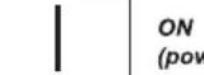 ver and Engine) ver and Engine) |  | IN-position of a bistable push control |  | Engine start (Electric start) | |
 | OFF(power and Engine) |  | Protective earth (ground) |  | Engine stop |
 | Alternating current |  | Fuse |  | Gasoline |
 | Direct current |  | Engine oil |  | Fast |
 | Plus ; positive polarity |  | Add oil |  | Slow |
 | Minus ; negative polarity |  | Battery charging condition |  | Fuel start / Open |
 | OUT-position of a bistable push control |  | Choke ; cold starting aid |  | Fuel stop / Close |
| [K004] | Rated power (kW) |  | Continuous power |  | Rated power factor |
 | Rated frequency (Hz) |  | Rated voltage (V) |  | Rated current (A) |
 | Maximum site altitude above sea-level (m) |  | Maximum ambient temperature (°C) | [9HZ7] | Mass (kg) |
RGX2900, RGX3600, RGX4800

RGX6500, RGX7500

①

②

③

④

5

6

⑦

8


⑨

⑪

1. SAFETY PRECAUTIONS
Please make sure you review each precaution carefully.
Pay special attention to statement preceded by the following words.

DANGER
"DANGER" indicates a possibility of death or serious injury if instructions are not followed.

WARNING
"WARNING" indicates a strong possibility of severe personal injury or loss of life if instructions are not followed.

CAUTION
"CAUTION" indicates a possibility of personal injury or equipment damage if instructions are not followed.

WARNING
Do not operate the generator near gasoline or gaseous fuel because of the potential danger of explosion or fire.
Do not fill the fuel tank with fuel while the engine is running. Do not smoke or use open flame near the fuel tank. Be careful not to spill fuel during refueling.
If fuel is spilt, wipe it off and let dry before starting the engine.


WARNING
Do not place in flammables near the generator.
Be careful not to place fuel, matches, gunpowder, oily cloths, straw, trash, or any other in flammables near the generator.

WARNING
Do not operate the generator inside a room, cave, tunnel, or other insufficiently ventilated area.
Always operate it in a well-ventilated area, otherwise the engine may become overheated, and the poisonous carbon monoxide gas, an odorless, colorless, poison gas, contained in the exhaust gas will endanger human lives.
Operate generator only outdoors and far from open windows, doors, ventilation intakes and other openings.
Keep the generator at least 1 meter (3 feet) away, including overhead, from any structure or building use.


WARNING
Do not enclose the generator nor cover it with a box.
The generator has a built-in forced air cooling system, and may become overheated if it is enclosed.
If generator has been covered to protect it from the weather during non use, be sure to remove it and keep it well away from the area during generator use.

WARNING
Operate the generator on a level surface.
It is not necessary to prepare a special foundation for the generator.
However, the generator will vibrate on an irregular surface, so choose a level place without surface irregularities.
If the generator is tilted or moved during operation, fuel may spill and / or the generator may tip over, causing a hazardous situation.
Proper lubrication cannot be expected if the generator is operated on a steep incline or slope. In such a case, piston seizure may occur even if the oil is above the upper level.

WARNING
Pay attention to the wiring or extension cords from the generator to the connected device.
If the wire is under the generator or in contact with a vibrating part, it may break and possibly cause a fire, generator burnout, or electric shock hazard.
Replace damaged or worn cords immediately.


WARNING
Do not operate in rain, in wet or damp conditions, or with wet hands.
The operator may suffer severe electric shock if the generator is wet due to rain or snow.

WARNING
If wet, wipe and dry it well before starting. Do not pour water directly over the generator, nor wash it with water.

WARNING
Be extremely careful that all necessary electrical grounding procedures are followed during each and every use. Failure to do so can be fatal.

WARNING
Do not contact the generator to a commercial power line. Connection to a commercial power line may short circuit the generator and ruin it or cause electric shock hazard. Use the transfer switch for connecting to domestic circuit.


WARNING
No smoking while handling the battery. The battery emits flammable hydrogen gas, which can explode if exposed to electric arcing or open flame. Keep the area well-ventilated and keep open flames/sparks away when handling the battery.


WARNING
Engine becomes extremely hot during and for some time after operation. Keep combustible materials well away from generator area. Be very careful not to touch any parts of the hot engine especially the muffler area or serious burns may result.


WARNING
Keep children and all bystanders at a safe distance from work areas.

WARNING
It is absolutely essential that you know the safe and proper use of the power tool or appliance that you intend to use. All operators must read, understand and follow the tool/appliance owners manual. Tool and appliance applications and limitations must be understood. Follow all directions given on labels and warnings. Keep all instruction manuals and literature in a safe place for future reference.

WARNING
Use only "LISTED" extension cords. When a tool or appliance is used outdoors, use only extension cords marked "For Outdoor Use". Extension cords, when not in use should be stored in a dry and well ventilated area.

WARNING
Always switch off generator's AC circuit protector and disconnect tools or appliances when not in use, before servicing, adjusting, or installing accessories and attachments.

CAUTION
Make sure the engine is stopped before starting any maintenance, servicing or repair. Make sure maintenance and repair of the generator set are performed by properly trained personnel only.

CAUTION
: PRECAUTIONS ON THE HANDLING OF THE WARNING LABEL
Warning labels are affixed to our engines with regard to particularly serious dangers. When using the engines, please use them safely after carefully reading the instruction manual and understanding the dangers.
Warning Label Exclusively for the United States and Canada


For use in the United States or Canada, please affix the label suited to the region from among the enclosed warning labels.
2. SPECIFICATIONS
| MODEL RGX2900 RGX3600 | RGX4800 RGX6500 RGX7500 | |||||
| Generator | Type | Brush-less, self-exciting, 2-poles, single phase | Brush, self-exciting, 2-poles, single phase | |||
| Voltage regulating system Condenser type AVR type | ||||||
| AC OutputRated voltage-Frequency V-Hz 120-60 | 120/240-60 | |||||
| Rated current A 20.0 24.1/12.0 34.1/17 | 0 41.7/20.8 50/25 | |||||
| Rated output VA (W) | 2400 | 2900 | 4100 | 5000 | 6000 | |
| Rated power factor | 1.0 | |||||
| Safety device type | Fuse-less circuit breaker | |||||
| DC OutputRated voltage V | 12 | |||||
| Rated current A | 8.3 | |||||
| Safety device type | Fuse-less circuit breaker | |||||
| Ground systemAC System | Neutral bonded to frame | |||||
| DC System | System floating | |||||
| Insulation class | B | |||||
| Engine | Model | EX17D | EX21D | EX27D | EX35D | EX40D |
| Type | SUBARU, Air-cooled, 4-stroke, OHC, Gasoline Engine | |||||
| Displacement mL (cu.in.) | 169 (10.31) | 211 (12.88) | 265 (16.17) | 404 (24.65) | ||
| Fuel | Automotive Unleaded Gasoline | |||||
| Fuel Tank Capacity L (U.S.gal) | 12.8 (3.38) | 22.0 (5.8) | ||||
| Engine oil capacity L (U.S.gal) | 0.6 (0.16) | 1.0 (0.26) | 1.2 (0.32) | |||
| Spark plug | BR-6HS (NGK) | |||||
| Starting system | Recoil starter | Electric starter / Recoil | ||||
| Dimension | Length mm (in.) | 580 (22.8) | 605 (23.8) | 650 (25.6) (815 (32.1))*1 | 710 (28.0) (875 (34.4))*1 | |
| Width mm (in.) | 420 (16.5) | 450 (17.7) | 510 (20.1) | 545 (21.5) | ||
| Height mm (in.) | 480 (18.9) | 500 (19.7) | 540 (21.3) | 595 (23.4) | ||
| Dry Weight kg (lb) | 48 (105.8) | 54 (119.1) | 70 (154.4) (73 (161))*2 | 84.4 (186.1) (87.4 (192.7))*2 | 93.5 (206.2) (96.5 (212.8))*2 | |
| Valve Clearance (Intake & Exhaust) mm (in.) | 0.12 +0.03 mm (0.0047 +0.0012 in.)Note: Adjust the valve clearance while the engine is cold. | |||||
Specifications are subject to change without notice.
NOTE
*1: ( ) shows dimensions with Battery frame.
*2: ( ) shows dry weight with Electric starter.
3. COMPONENTS
RGX2900, RGX3600, RGX4800


RGX6500, RGX7500


CONTROL PANEL
(RGX4800)

(RGX2900)

(RGX3600)

(RGX6500, 7500)

4. PRE-OPERATION CHECKS
CHECK ENGINE OIL
Before checking or refilling oil, be sure generator is located on stable and level surface with engine stopped.
Remove oil filler cap and check the engine oil level.
If oil level is below the lower level line, refill with suitable oil (see table) to upper level line. Do not screw in the oil filler cap when checking oil level.
Change oil if contaminated.
(See "How-To" Maintenance.)
| Oil capacity (Upper level) : L(U.S. gal) | |
| RGX2900 | 0.6 (0.15) |
| RGX3600 | 0.6 (0.15) |
| RGX4800 | 1.0 (0.26) |
| RGX6500 | 1.2 (0.32) |
| RGX7500 | 1.2 (0.32) |

Recommended engine oil:
Use 4-stroke automotive detergent oil of API service class SE or higher grade (SG, SH or SJ is recommended). SAE 10W-30 or 10W-40 is recommended for general, all-temperature use. If single viscosity oil is used, select the appropriate viscosity for the average temperature in your area.

bar
| Category | Temperature Range (°C) | Ambient temperature | |---|---|---| | Single grade | -20 to 5W | -4 to 0 | | Single grade | -10 to 20W | 0 to 10 | | Single grade | -10 to 20W #20 | 10 to 20 | | Single grade | -10 to 20W #30 | 20 to 30 | | Single grade | -10 to 20W #40 | 30 to 40 | | Multigrade | -20 to 10W-30 | -4 to 0 | | Multigrade | -10 to 10W-40 | 10W-30 to 40W-40 | | Ambient temperature | -20 to 40°C | 86 to 104°F |CHECK ENGINE FUEL.

WARNING
Do not refuel while smoking or near open flame or other such potential fire hazards. Otherwise fire accident may occur.
NOTE : THIS ENGINE IS CERTIFIED TO OPERATE ON AUTOMOTIVE UNLEADED GASOLINE.
Check fuel level at fuel level gauge.
If fuel level is low, refill with unleaded automotive gasoline.
Stop the engine and open the cap.
Close the fuel valve before filling the fuel tank.
Be sure to use the fuel filter screen on the fuel filter neck.
Reattach the fuel cap by turning clockwise until reaching the physical stop (about one quarter turn). Do not attempt to turn past the physical stop or the fuel cap may be damaged.
Fuel Amount
up to "LEVEL" position : L (U.S. gal)
| RGX2900 | 12.0 (3.17) |
| RGX3600 | 12.0 (3.17) |
| RGX4800 | 12.0 (3.17) |
| RGX6500 | 22.0 (5.8) |
| RGX7500 | 22.0 (5.8) |


WARNING
Make sure you review each warning in order to prevent fire hazard.
Do not refill tank while engine is running or hot.
Close fuel valve before refueling with fuel.
Be careful not to admit dust, dirt, water or other foreign objects Into fuel.
Wipe off spilt fuel thoroughly before starting engine.
Keep open flames away.
CHECKING COMPONENT PARTS
Check following items before starting engine:
Fuel leakage from fuel hose, etc.
Bolts and nuts for looseness.
Components for damage or breakage.
Generator not resting on or against any adjacent wiring.
CHECK GENERATOR SURROUNDINGS

WARNING
Make sure you review each warning in order to prevent fire hazard.
Keep area clear of in flammables or other hazardous materials.
Keep generator at least 3 feet (1 meter) away from buildings or other structures.
Only operate generator in a dry, well ventilated area.
Keep exhaust pipe clear of foreign objects.
Keep generator away from open flame. No smoking!
Keep generator on a stable and level surface.
Do not block generator air vents with paper or other material.
BATTERY INSTALLATION (RGX4800, 6500, 7500 w/Electric Starter)
Recommended Battery
Type ; Lead-acid battery
Capacity (Ah/5hr) ; 12V-21AH or more
Size ; Less than 185(L) x 125(W) x 160(H) mm


WARNING
Death, personal injury and/or property damage may occur unless instructions are followed carefully.
Use battery of recommended capacity.
Turn the starter switch to the “STOP” position when mounting or dismounting battery. When mounting battery, connect the positive (+) cable first and then the negative (−) cable to the battery. Be careful not to short battery cables. When dismounting battery, disconnect negative (−) cable first.
RED CABLE : To positive (+) terminal BLACK CABLE : To negative ( - ) terminal
Should the connection be made in incorrect manner, the generator will be broken.
Tighten bolts and nuts on terminals securely so they will not be loosened by vibration.
Disconnect battery cables when charging battery.
GROUNDING THE GENERATOR
To ground the generator to the earth, connect the grounding lug of the generator to the grounding spike driven into the earth or to the conductor which has been already grounded to the earth.
such grounding conductor or grounding electrode is unavailable, connect the grounding lug of the generator to the grounding terminal of the using electric tool or appliance.


natural_image
Simple line drawing of a valve and a circular symbol (no text or labels)5. OPERATING PROCEDURES
STARTING THE GENERATOR
[CAUTION]
Check the oil level before each operations as outlined by the article "CHECK ENGINE OIL"
(a) Turn the Engine switch to the position "ON".
(b) Turn the AC circuit breaker to the position "OFF".
(c) Open the fuel valve.
(d) Set choke lever to close if the engine is cold.


(e) Pull the starter handle slowly until passing the compression point (resistance will be felt), then return the handle to its original position and pull briskly.
If the engine fails to start after several attempts, repeat above procedures with choke lever returned to "OPEN" position.
Do not fully pull out the rope.
After starting, allow the starter handle to return to its original position while still holding the handle.

(f) After the engine started, return the choke lever gradually to "OPEN" position.

(g) Warm up the engine without a load for a few minutes.
USING ELECTRIC POWER

WARNING
Make sure that the appliance is switched OFF before connecting it to the generator.
Do not move the generator while it is running.
Be sure to ground the generator if the connected appliance is grounded. Failure to ground unit may lead to electrical shock.
(1) AC APPLICATION
(a) Make sure the pilot lamp is turned on.
(b) Turn off the switch (es) of the electrical appliance (s) before connecting to the generator.
(c) Insert the plug (s) of the electrical appliance(s) into the receptacle.

Check the amperage of the receptacles used referring to TABLE 1, and be sure not to take a current exceeding the specified amperage.
Be sure that the total wattage of all appliances dose not exceed the rated output of the generator.
| Style Ampere | Receptacle AC plug Description | |||
 | up to 20A | NEMA5-20R | NEMA5-20P | GFCI (Ground Fault Circuit Interrupter)Receptacle,duplex(REC1) |
 | up to 20A | NEMAL14-20R | NEMAL14-20P | LockingReceptacle(REC2) |
 | up to 30A | NEMAL5-30R | NEMAL5-30P | LockingReceptacle(REC3) |
 | up to 30A | NEMAL14-30R | NEMAL14-30P | LockingReceptacle(REC4) |
TABLE 1
WARNING
To take power out from the TWIST LOCK RECEPTACLE, insert the plug into the receptacle, and turn it clockwise to the lock position.
■Be sure to ground the generator if the connected electrical device is grounded.

NOTE :
When the AC circuit breaker turns off during operation, the generator is over loaded or the appliance is defective. Stop the generator immediately, check the appliance and / or generator for overloading or detect and have repaired as necessary by SUBARU Industrial Power Products dealer or service shop.
[CAUTION]
The duplex 120V receptacle is protected by a GFCI (Ground Fault Circuit Interrupter). GFCI shuts off the output current from the duplex 120V receptacle when a ground fault occurs in the generator or the appliance. Please note that other receptacles are not protected by GFCI.
(d) Check and confirm whether circuit breaker position is "ON".
(e) Turn on the switch of the appliance.

GFCI RECEPTACLE
After starting the engine, check the GFCI for proper functioning by the following test procedure.
Push blue TEST button, The red RESET button will pop out exposing the word TRIP. Power is now off at the outlets protected by the GFCI, indicating that the device is functioning properly.
If TRIP dose not appear when testing, do not use the generator. Call a qualified electrician.
To restore power, push RESET button.

WARNING
If the RESET button pops out during operation, stop the generator immediately and call a qualified electrician for checking generator and the appliances.
FULL POWER SWITCH (Except RGX2900)
Select the voltage using the FULL
POWER SWITCH in accordance with the electrical appliance.
Refer to TABLE 2.

[CAUTION]
Change the FULL POWER SWITCH after turning the AC circuit breaker to "OFF".
| Switch position Lower Voltage Receptacle Higher Voltage Receptacle | ||
| 120V Activated full rated output N.A | ||
| 120/240V Activated half of rated output Activated full rated output | ||
TABLE 2
IDLE CONTROL SWITCH (Except RGX2900)
IDLE CONTROL SWITCH automatically reduces engine speed when load is OFF, and automatically increases engine speed to rated r.p.m. when load is ON.
IDLE CONTROL SWITCH provides fuel economy and low noise operation at no-load running.
(1) HOW TO USE IDLE CONTROL SWITCH
Start the engine with IDLE CONTROL SWITCH off.
NOTE :
Warm up the engine without a load for a few minutes.
Turn IDLE CONTROL SWITCH on.

(2) CHECKING THE OPERATION
When IDLE CONTROL SWITCH does not operate normally, please check following :
Overloaded?
Please make it sure that the generator is not overload.
NOTE :
Most induction loads such as electric motors require three to five times more wattage than their ratings during starting.
This starting wattage should not exceed the rated output of the generator for proper operation of IDLE CONTROL SWITCH.
■Turn IDLE CONTROL SWITCH off when the IDLE CONTROL SWITCH does not work normally under the rated output.
NOTE :
The IDLE CONTROL SWITCH may not operate when the applied load is under 40W. In such cases turn the IDLE CONTROL SWITCH off.
(3) STOPPING THE ENGINE
Turn off the switch of load.
Switch off generator's AC breaker.
■Disconnect tool or appliance.
■Turn the IDLE CONTROL SWITCH off.
Turn the STOP SWITCH to the position "O" (OFF).
NOTE :
Allow the engine about 3 minutes to cool down at no-load before stopping.
(2) DC APPLICATION
The DC terminal is used only for charging 12 volt batteries.
It provides up to 12V-8.3A (100W) of maximum power.
CONNECTION OF CABLE :
Connect positive (red) terminal on generator to positive (+) terminal on battery.
Connect negative (black) terminal on generator to negative (-) terminal on battery.
Both AC and DC output can be used at the same time if the total output is within rated output of the generator.

SAFETY PRECAUTIONS WHILE CHARGING
An explosive hydrogen gas is discharged through vent holes in the battery during the charging process. Do not allow spark or open flame around the generator or battery during the charging process.
Electrolyte fluid can burn eyes and clothing. Be extremely careful to avoid contact. If injured, wash the affected area immediately with large quantities of water and consult a doctor for treatment.
When charging a large capacity battery or totally discharged battery, excessive current may force the DC protector to turn off.
In such cases, use a battery charger to charge a large battery with AC output.
Battery defects may cause the DC protector to turn off.
Check the battery before replacing the DC protector.
STOPPING THE GENERATOR
(a) Turn off the power switch of the electric equipment and unplug the cord from receptacle of the generator.
(b) Turn the AC circuit breaker to the "OFF" position.
(c) Allow the engine about 3 minutes to cool down at no-load before stopping.
(d) Turn the Engine switch to the position "OFF".
(e) Close the fuel valve.
OIL SENSOR
(a) The oil sensor detects the fall in oil level in the crankcase and automatically stops the engine when the oil level falls below a predetermined level.
(b) When engine has stopped automatically, switch off generator's AC circuit breaker, and check the oil level.
Refill engine oil to the upper level as instructed on page 6 and restart the engine.
(c) If the engine does not start by usual starting procedures, check the oil level.


6.WATTAGE INFORMATION
Some appliances need a "surge" of energy when starting.
This means that the amount of electrical power needed to start the appliance may exceed the amount needed to maintain its use.
Electrical appliances and tools normally come with a label indicating voltage, cycles / Hz, amperage (amps) and electrical power needed to run the appliance or tool.
Check with your nearest dealer or service center with questions regarding power surge of certain appliances or power tools.
Electrical loads such as incandescent lamps and hot plates require the same wattage to start as is needed to maintain use.
■loads such as fluorescent lamps require 1.2 to 2 times the indicated wattage during start-up.
■loads for mercury lamps require 2 to 3 times the indicated wattage during start-up.
Electrical motors require a large starting current. Power requirements depend on the type of motor and its use. Once enough “surge” is attained to start the motor, the appliance will require only 50% to 30% of the wattage to continue running.
Most electrical tools require 1.2 to 3 times their wattage for running under load during use. For example, a 5,000 watt generator can power a 1800 to 4000 watt electrical tool.
■loads such as submersible pumps and air compressors require a very large force to start. They need 3 to 5 times the normal running wattage in order to start. For example, a 5,000 watt generator would only be able to drive a 1,000 to 1,700 watt pump.
NOTE:
The following wattage chart is general guide only. Refer to your specific appliance for correct wattage.
To determine the total wattage required to run a particular electrical appliance or tool, multiply the voltage figure of the appliance/tool by the amperage (amps) figure of same. The voltage and amperage (amps) information can be found on a name plate which is normally attached to electrical appliances and tools.
| Applications | Applicable Wattage(W) | ||||
| RGX2900 RGX3600 RGX4800 RGX6500 RGX7500 | |||||
| Incandescent lamp, Heater 2400 2900 4100 5000 6000 | |||||
| Fluorescent lamp, Electric tool 1200 1500 2100 2750 3300 | |||||
| Mercury lamp 900 1100 1500 2000 2400 | |||||
| Pump, Compressor 550 650 950 1250 1500 | |||||
VOLTAGE DROP IN ELECTRIC EXTENSION CORDS
When a long electric extension cord is used to connect an appliance or tool to the generator, a certain amount of voltage drop or loss occurs in the extension cord which reduces the effective voltage available for the appliance or tool.
The chart below has been prepared to illustrate the approximate voltage loss when an extension cord of 300 feet (approx. 100 meters) is used to connect an appliance or tool to the generator.
| Nominal cross section | A.W.G. | Allowable current | No.of strands / strands dia. | Resistance | Current Amp. | |||||||
| mm^2 | No. A No./mm | Ω/100m 1 | A 3A 5 | A 8A 1 | 0A 12 | A 15A | Voltage drop | |||||
| 0.75 18 | 7 30/0.18 | 2.477 2.5V 8V | 12.5V | — | — | — | — | |||||
| 1.27 16 | 12 50/0.16 | 1.486 1.5V 5V | 7.5V 12V 15V | 18V | — | |||||||
| 2.0 | 14 17 | 37/0.26 0.952 | 1V 3V 5V | 8V 10V 12V | 15V | |||||||
| 3.5 12 to 10 | 23 45/0.32 0.517 | — | 1.5V | 2.5V | 4V 5V | 6.5V | 7.5V | |||||
| 5.5 | 10 to 8 | 35 70/0 | 32 0.332 | — | 1V 2 | V 2.5V | 3.5V | 4V 5V | ||||
7. SPARK ARRESTER
In a dry or wooded area, it is recommendable to use the product with a spark arrester. Some areas require the use of a spark arrester. Please check your local laws and regulations before operating your product.
The spark arrester must be cleaned regularly to keep it functioning as designed. A clogged spark arrester :
●Prevents the flow of exhaust gas
- Reduces engine output
- Increases fuel consumption
●Makes starting difficult
If the engine has been running, the muffler and the spark arrester will be very hot. Allow the muffler to cool before cleaning the spark arrester.


How to remove the spark arrester
- Remove the flange bolts from the muffler cover and remove the muffler cover.
- Remove the special screw from the spark arrester and remove the spark arrester from the muffler.
Clean the spark arrester screen
Use a brush to remove carbon deposits from the spark arrester screen. Be careful to avoid damaging the screen.
The spark arrester must be free of breaks and holes. Replace the spark arrester if it is damaged.
Install the spark arrester, and muffler protector in the reverse order of disassembly.

8. MAINTENANCE SCHEDULE
MAINTENANCE, REPLACEMENT, OR REPAIR OF THE EMISSION CONTROL DEVICES AND SYSTEMS MAY BE PERFORMED BY ANY NONROAD ENGINE REPAIR ESTABLISHMENT OR INDIVIDUAL.
DAILY INSPECTION
Before running the generator, check the following service items:

PERIODIC MAINTENANCE
Periodic maintenance is vital to safe and efficient operation of your generator. Check the table below for periodic maintenance intervals.
IT IS ALSO NECESSARY FOR THE USER OF THIS GENERATOR TO CONDUCT THE MAINTENANCE AND ADJUSTMENTS ON THE EMISSION-RELATED PARTS LISTED BELOW TO KEEP THE EMISSION CONTROL SYSTEM EFFECTIVE.
The emission control system consists of the following parts :
(1) Carburetor and internal parts
(2) Cold start enrichment system, if applicable
(3) Intake manifold, if applicable
(4) Air cleaner elements
(5) Spark plug
(6) Magneto or electronic ignition system
(7) Spark advance/retard system, if applicable
(8) Exhaust manifold, if applicable
(9) Hoses, belts, connectors, and assemblies
The maintenance schedule indicated in the table is based on the normal generator operation. Should the generator be operated in extremely dusty condition or in heavier loading condition, the maintenance intervals must be shortened depending on the contamination of oil, clogging of filter elements, wear of parts, and so on.
Periodic Maintenance Schedule table
| Maintenance Items | Every 8 hours (Daily) | Every 50 hours (Weekly) | Every 200 hours (Monthly) | Every 500 hours | Every 1000 hours |
| Clean generator and check bolt and nuts | ● (Daily) | ||||
| Check for leakage from hoses and fi tting | ● (Daily) | ||||
| Check and refi ll engine oil | ● (Refi ll daily up to upper level) | ||||
| Change engine oil (*Note1) | ● (Initial 20 hours) | ● (Every 100 hours) | |||
| Clean spark plug | ● (Every 100 hours) | ||||
| Clean air cleaner | ● | ||||
| Clean spark arrester | ● (Every 100 hours) | ||||
| Replace air cleaner element | ● | ||||
| Clean fuel fi lter | ● | ||||
| Clean and adjust spark plug and electrodes | ● | ||||
| Replace spark plug | ● | ||||
| Remove carbon from cylinder head (*Note 2) | ● | ||||
| Check and adjust valve clearance (*Note 2) | ● | ||||
| Clean and adjust carburetor (*Note 2) | ● | ||||
| Clean and replace carbon brushes | ● | ||||
| Replace fuel lines | ● (Every 2 years) | ||||
| Overhaul engine (*Note 2) | ● | ||||
| Check AC receptacles | ● (Daily) | ||||
| Check DC termianl | ● (Daily) | ||||
| Check engine switch | ● (Daily) | ||||
| Check rotor | ● | ||||
| Check stator | ● | ||||
| Replace engine mount | ● |
*Note: 1. Initial oil change should be performed after first twenty (20) hours of operation.
Thereafter change oil every hundred (100) hours.
Before changing oil, check for a suitable way to dispose of old oil.
Do not pour it down into sewage drains, onto garden soil or into open streams.
Your local zoning or environmental regulations will give you more detailed instructions on proper disposal.
*Note: 2. As to the procedures for these items, please refer to the SERVICE MANUAL or consult your nearest service dealer.
9. "HOW-TO" MAINTENANCE
ENGINE OIL CHANGE
Change engine oil every 100 hours. (For new engine, change oil after 20 hours.)
(a) Drain oil by removing the drain plug and the oil filler cap while the engine is warm.

(b) Reinstall the drain plug and fill the engine with oil until it reaches the upper level on the oil filler cap.
Use fresh and high quality lubricating oil to the specified level as directed on page 6. If contaminated or deteriorated oil is used or the quantity of the engine oil is not sufficient, the engine damage will result and its life will be greatly shortened.
SERVICING THE AIR CLEANER
Maintaining an air cleaner in proper condition is very important.
Dirt induced through improperly installed, improperly serviced or inadequate elements damages and wears out engines. Keep the element always clean.
(a) Remove the bolt of air cleaner cover. (RGX6500, 7500) Remove the air cleaner cover and cleaner element.
(b) Urethane form: Wash urethane form element in kerosene or diesel fuel. Then saturate the element in a mixture of 3 parts kerosene or diesel fuel and 1 part engine oil. Squeeze the element to remove the mixture and install it in the air cleaner.
NOTE :
Instead of washing oil (kerosene), it is possible to wash the urethane foam element in a solution of mild detergent and warm water.
Then rinse the element thoroughly in clean water.
Allow the element to dry thoroughly. Soak the element in clean engine oil and squeeze out excess oil.
RGX2900, 3600 RGX4800 RGX6500, 7500


CLEANING AND ADJUSTING SPARK PLUG
(a) If the plug is contaminated with carbon, remove it using a plug cleaner or wire brush.
(b) Adjust the electrode gap to 0.6 to 0.7 mm (0.024 to 0.028 in.).
Spark plug : BR-6HS (NGK)

CLEANING FUEL STRAINER
Dirt and water in the fuel are removed by the fuel strainer.
(a) Remove the strainer cup and throw away water and dirt.
(b) Clean the screen and strainer cup with gasoline.
(c) Tightly fasten the cup to main body, making sure to avoid fuel leak.

natural_image
Exploded view diagram of a mechanical device showing internal components (no text or labels)Please have an authorized SUBARU Industrial Power Products service dealer modify this engine if it is to be run continuously above 5,000 feet (1,500 meters). Failure to do so, may result in poor engine performance, spark plug fouling, hard starting, and increased emissions.
Carburetor modification by an authorized SUBARU Industrial Power Products service dealer will improve performance and allow that this engine meets EPA (Environmental Protection Agency) and California ARB (Air Resources Board) emission standards throughout its useful life.
An engine converted for high altitudes can not be run at 5,000 feet or lower. In doing so, the engine will overheat and cause serious engine damage. Please have an authorized SUBARU Industrial Power Products service dealer restore high altitude modified engines to the original factory specification before operating below 5,000 feet.
CHECKING CARBON BRUSH (RGX6500, 7500)
If the brush become excessively worn, its contact pressure with the slip ring changes and causes a roughened surface on the slip ring, resulting in irregular generator performance.
Check the brush every 500 hours or if generator performance is irregular.
If the brush is 5 mm long or less, replace it with a new one.

(a) Remove the brush cover.
(b) Disconnect the wire connector and remove the brush.
(c) Carefully note the brush direction and relative position with the slip ring when installing new brush.

10. PREPARATION FOR STORAGE
The following procedures should be followed prior to storage of your generator for periods of 6 months or longer.
Drain fuel from fuel tank carefully by disconnecting the fuel line. Gasoline left in the fuel tank will eventually deteriorate making engine-starting difficult.
Remove the carburetor float chamber and also drain the carburetor.
Change engine oil.
Check for loose bolts and screws, tighten them if necessary.

Clean generator thoroughly with oiled cloth. Spray with preservative if available. NEVER USE WATER TO CLEAN GENERATOR!
Pull starter handle until resistance is felt, leaving handle in that position.
Store generator in a well ventilated, low humidity area.
11. TROUBLESHOOTING
When generator engine fails to start after several attempts, or if no electricity is available at the output socket, check the following chart. If your generator still fails to start or generate electricity, contact your nearest SUBARU Industrial Power Products dealer or service shop for further information or corrective procedures.
When Engine Fails to Start:
| Check if choke lever is in its proper position. |  | Set the choke lever to “CLOSE” position. |
| Check if fuel valve is open. If closed, open f | ||
| Check fuel level. | If empty, refill fuel tank making sure not to overfill. | |
| Check if engine switch is in OFF. Turn engine switch to ON. | ||
| Check to make sure generator is not connected to an appliance. |  | If connected, turn off the power switch on the connected appliance and unplug. |
| Check spark plug for loose spark plug cap. | If loose, push spark plug cap back into place. | |
| Check spark plug for contamination. Remove spark plug | and clean electrode. |
When No Electricity Is Generated at Receptacle:
| Check to make sure AC circuit breaker is in the “ON” position. |  | After making sure that the total wattage of the electrical appliance is within permissible limits and there are no defects in the appliance, turn the AC circuit breaker to the “ON” position. If protectors continue to actuate, consult your nearest servicing dealer. |
| Check AC receptacle and DC terminals for loose connection. |  | Secure connection if necessary. |
| Check to see if engine starting was attempted with appliances already connected to generator. | Turn off switch on the appliance, and disconnect cable from receptacle. Reconnect after generator has been started properly. | |
| Low power. Carbon brushes are excessively worn |
12. WIRING DIAGRAM
RGX2900 (60Hz-120V)

flowchart
graph TD
    subgraph CONTROL BOX
        A["Engine"] --> B["Oil sensor"]
        B --> C["Ignition coil"]
        C --> D["Spark plug"]
        D --> E["Generator"]
        E --> F["Condenser Winding"]
        F --> G["Pipe frame"]
    end

    subgraph GENERATOR
        H["Engine"] --> I["Blk"]
        I --> J["Engine switch"]
        J --> K["AC circuit breaker 20A"]
        K --> L["Blu"]
        L --> M["Hr"]
        M --> N["Pilot lamp"]
        N --> O["PL"]
        O --> P["Rec1 20A"]
        P --> Q["Gry"]
        Q --> R["Earth (Ground) terminal"]
    end

    subgraph Wiring Color Code
        S["Blk: Black"] & T["Blk/W: Black/White"] & U["Blu: Blue"] & V["LBlu: Light blue"] & W["Organ: Orange"] & X["Y: Yellow"] & Y["W/Blk: White/Black"] & Z["Gry: Gray"] & AA["Red: Grn/Y: Green/Yellow"] & AB["Pur: Purple"]
    end
RGX3600 (60Hz-120/240V)

flowchart
graph TD
    subgraph Engine
        A["Oil sensor"] --> B["Ignition coil"]
        B --> C["Spark plug plug"]
        C --> D["Solenoid"]
        D --> E["Charge coil"]
        E --> F["Blk"]
        F --> G["Blu"]
        G --> H["LBlu"]
        H --> I["Idle control switch"]
        I --> J["Control Box"]
        J --> K["Engine switch"]
        K --> L["Gm"]
        L --> M["3"]
        M --> N["2"]
        N --> O["1"]
        O --> P["5"]
        P --> Q["AC circuit protector 20A"]
        Q --> R["Gm"]
    end

    subgraph Generator
        S["Rotor Field Winding"] --> T["AC Winding 1"]
        T --> U["Blk"]
        U --> V["Hr Hour meter"]
        V --> W["Blu"]
        W --> X["R"]
        X --> Y["R"]
        Y --> Z["Pilot lamp"]
        Z --> AA["AC circuit breaker 13A"]
        AA --> AB["Pilot lamp"]
        AB --> AC["Blu"]
        AC --> AD["Full power switch 1"]
        AD --> AE["Blu"]
        AE --> AF["3"]
        AF --> AG["4"]
        AG --> AH["5"]
        AH --> AI["6"]
        AI --> AJ["7"]
        AJ --> AK["8"]
        AK --> AL["9"]
        AL --> AM["10"]
        AM --> AN["11"]
        AN --> AO["12"]
        AO --> AP["W"]
        AP --> AQ["W"]
        AQ --> AR["W"]
        AR --> AS["W"]
    end

    subgraph Wiring Color Code
        AT["Condenser Winding"] --> AU["AC Winding 2"]
        AU --> AV["W"]
        AV --> AW["Pilot lamp"]
        AW --> AX["W"]
        AX --> AY["W"]
        AY --> AZ["W"]
        AZ --> BA["W"]
        BA --> BB["W"]
        BB --> BC["Diode stack Assy"]
        BC --> BD["Org"]
        BD --> BE["Circuit protector 10A"]
        BE --> BF["DC output terminal"]
        BG["Condenser"] --> BH["Y"]
        BH --> BI["Y"]
        BI --> BJ["Condenser"]
    end

    style Engine fill:#f9f,stroke:#333
    style Generator fill:#ccf,stroke:#333
    style Wiring Color Code fill:#cfc,stroke:#333
Wiring color code
Blk : Black
Blk/W : Black/White
Blu : Blue
LBlu : Light blue
Brn : Brown
Brn/W : Brown/White
Gm:Green
Grn/W : Green/White
Org : Orange
Gry : Gray
R : Red
W : White
Y: Yellow
W/Blk : White/Black
Gm/Y : Green/Yellow
Pur : Purple
RGX4800 (60Hz-120/240V)

flowchart
graph TD
    subgraph ENGINE_CONTROL_BOX
        direction TB
        A["Oil sensor"] --> B["Ignition coil"]
        B --> C["Charge coil"]
        C --> D["Blk"]
        D --> E["LBlu"]
        E --> F["Idle control switch"]
        F --> G["Idle control unit"]
        G --> H["AC circuit protector 20A"]
        H --> I["Full power switch"]
        I --> J["AC circuit breaker 20A"]
        J --> K["Pilot lamp"]
        K --> L["Blu"]
        L --> M["Hr"]
        M --> N["Hour meter"]
        N --> O["R"]
        O --> P["R"]
        P --> Q["Blu"]
        Q --> R["AC Winding 1"]
        R --> S["Condenser Winding"]
        S --> T["Brn"]
        T --> U["DC Winding"]
        U --> V["Y"]
        V --> W["Y"]
        W --> X["Condenser"]
    end

    subgraph GENERATOR
        direction TB
        Y["Rotor"] --> Z["AC Winding 1"]
        Z --> AA["Blk"]
        AA --> AB["Hr"]
        AB --> AC["Hour meter"]
        AC --> AD["PL"]
        AD --> AE["R"]
        AE --> AF["W"]
        AF --> AG["W"]
        AG --> AH["W"]
        AH --> AI["Blu"]
        AI --> AJ["AC circuit breaker 30A"]
        AJ --> AK["R"]
        AK --> AL["Blu"]
        AL --> AM["W"]
        AM --> AN["W"]
        AN --> AO["Diode stack Assy"]
        AO --> AP["Org"]
        AP --> AQ["Circuit protector 15A"]
        AQ --> AR["DC output terminal"]
        AR --> AS["Bry/W"]
        AS --> AT["Blu"]
        AT --> AU["REC4 30A"]
        AU --> AV["Gry"]
        AV --> AW["H"]
        AW --> AX["G"]
        AX --> AY["Y"]
        AY --> AZ["Gry 30A"]
        AZ --> BA["Gry"]
        BA --> BB["Gry 30A"]
    end

    C --> BC["Solenoid"]
    D --> BD["Spark plug"]
    E --> BE["Engine switch"]
    F --> BF["Idle control unit"]
    G --> BG["AC circuit protector 20A"]
    H --> BH["Full power switch"]
    I --> BI["AC circuit breaker 20A"]
    J --> BJ["PILOT lamp"]
    K --> BK["Blu"]
    L --> BL["Hr"]
    M --> BM["Hour meter"]
    N --> BN["R"]
    O --> BO["R"]
    P --> BP["W"]
    Q --> BQ["W"]
    R --> BR["W"]
    S --> BS["W"]
    T --> BT["W"]
    U --> BU["Y"]
    V --> BV["Y"]
    W --> BW["Y"]

    subgraph OUTPUT_SIZE
        direction TB
        X["RECA 20A"] --> Y
        Y --> Z
        AA --> AA
        AB --> AA
        AC --> AB
        AD --> AB
        AE --> AB
        AF --> AB
        AG --> AB
        AH --> AB
        AI --> AJ["X"]
        AJ --> AK["Gry 30A"] --> AL["Gry"]
        AM --> AM
        AN --> AN
        AO --> AO
        AP --> AP
        AQ --> AQ
        AR --> AR
        AS --> AS
        AT --> AT
        AU --> AU
        AV --> AV
        AW --> AW
        AX --> AX
        AY --> AY
        AZ --> AZ
        BA --> BA
    end

    style ENGINE_CONTROL_BOX fill:#f9f,stroke:#333
    style GENERATOR fill:#ccf,stroke:#333

Wiring color code
Blk : Black
Blk/W : Black/White
Blu : Blue
LBlu : Light blue
Brn : Brown
Brn/W : Brown/White
Grn : Green
Grn/W : Green/White
Org : Orange
Gry : Gray
R: Red
W: White
Y : Yellow
W/Blk : White/Black
Grn/Y : Green/Yellow
Pur : Purple
RGX4800[w / Starter motor] (60Hz-120/240V)

RGX6500,7500 (60Hz-120/240V)

flowchart
graph TD
    subgraph Engine_CONTROL_BOX_GENERATOR
        direction TB
        CON.UN["CON. UN"] -->|W, W, LBIu, Bu| Idle_Solenoid["Idle solenoid"]
        AC_Circuit_protector1["AC circuit protector"] -->|Bk, REC1 20A| Full_PowerSwitch["Full power switch"]
        AC_Circuit_protector2["AC circuit protector"] -->|Bk, REC1 20A| Full_PowerSwitch
        AC_Circuit_protector3["AC circuit protector"] -->|Bk, REC3 30A| Full_PowerSwitch
        AC_Circuit_protector4["AC circuit protector"] -->|Bk, REC4 30A| Full_PowerSwitch
        AC_Circuit_protector5["AC circuit protector"] -->|Bk, REC1 20A| Full_PowerSwitch
        AC_Circuit_protector6["AC circuit protector"] -->|Bk, REC1 20A| Full_PowerSwitch
        AC_Circuit_protector7["AC circuit protector"] -->|Bk, REC1 20A| Full_PowerSwitch
        AC_Circuit_protector8["AC circuit protector"] -->|Bk, REC1 20A| Full_PowerSwitch
        AC_Circuit_protector9["AC circuit protector"] -->|Bk, REC1 20A| Full_PowerSwitch
        AC_Circuit_protector10["AC circuit protector"] -->|Bk, REC1 20A| Full_PowerSwitch
        AC_Circuit_protector11["AC circuit protector"] -->|Bk, REC1 20A| Full_PowerSwitch
        AC_Circuit_protector12["AC circuit protector"] -->|Bk, REC1 20A| Full_PowerSwitch
        AC_Circuit_protector13["AC circuit protector"] -->|Bk, REC1 20A| Full_PowerSwitch
        AC_Circuit_protector14["AC circuit protector"] -->|Bk, REC1 20A| Full_PowerSwitch
        AC_Circuit_protector15["AC circuit protector"] -->|Bk, REC1 20A| Full_PowerSwitch
        AC_Circuit_protector16["AC circuit protector"] -->|Bk, REC1 20A| Full_PowerSwitch
        AC_Circuit_protector17["AC circuit protector"] -->|Bk, REC1 20A| Full_PowerSwitch
        AC_Circuit_protector18["AC circuit protector"] -->|Bk, REC1 20A| Full_PowerSwitch
        AC_Circuit_protector19["AC circuit protector"] -->|Bk, REC1 20A| Full_PowerSwitch
        AC_Circuit_protector20["AC circuit protector"] -->|Bk, REC1 20A| Full_PowerSwitch
        AC_Circuit_protector21["AC circuit protector"] -->|Bk, REC1 20A| Full_PowerSwitch
        AC_Circuit_protector22["AC circuit protector"] -->|Bk, REC1 20A| Full_PowerSwitch
        AC_Circuit_protector23["AC circuit protector"] -->|Bk, REC1 20A| Full_PowerSwitch
        AC_Circuit_protector24["AC circuit protector"] -->|Bk, REC1 20A| Full_PowerSwitch
        AC_Circuit_protector25["AC circuit protector"] -->|Bk, REC1 20A| Full_PowerSwitch
        AC_Circuit_protector26["AC circuit protector"] -->|Bk, REC1 20A| Full_PowerSwitch
        AC_Circuit_protector27["AC circuit protector"] -->|Bk, REC1 20A| Full_PowerSwitch
        AC_Circuit_protector28["AC circuit protector"] -->|Bk, REC1 20A| Full_PowerSwitch
        AC_Circuit_protector29["AC circuit protector"] -->|Bk, REC1 20A| Full_PowerSwitch
        AC_Circuit_protector30["AC circuit protector"] -->|Bk, REC1 20A| Full_PowerSwitch
        AC_Circuit_protector31["AC circuit protector"] -->|Bk, REC1 20A| Full_PowerSwitch
        AC_Circuit_protector32["AC circuit protector"] -->|Bk, REC1 20A| Full_PowerSwitch
        AC_Circuit_protector33["AC circuit protector"] -->|Bk, REC1 20A| Full_PowerSwitch
        AC_Circuit_protector34["AC circuit protector"] -->|Bk, REC1 20A| Full_PowerSwitch
        AC_Circuit_protector35["AC circuit protector"] -->|Bk, REC1 20A| Full_PowerSwitch
        AC_Circuit_protector36["AC circuit protector"] -->|Bk, REC1 20A| Full_PowerSwitch
        AC_Circuit_protector37["AC circuit protector"] -->|Bk, REC1 20A| Full_PowerSwitch
        AC_Circuit_protector38["AC circuit protector"] -->|Bk, REC1 20A| Full_PowerSwitch
        AC_Circuit_protector39["AC circuit protector"] -->|Bk, REC1 20A| Full_PowerSwitch
        AC_Circuit_protector40["AC circuit protector"] -->|Bk, REC1 20A| Full_PowerSwitch
    end

    subgraph Power_Switch
        FullPowerSwitch["Full power switch"]
        FullPowerSwitch_Ru["W"]
        FullPowerSwitch_Bu["W"]
        FullPowerSwitch_Gm["W"]
        FullPowerSwitch_Bu["Gm"]
    end

    subgraph Control_Control_Control_Control_Control_Control_Control_Control_Control_Control_Control_Control_Control_Control_Control_Control_Control_Control_Control_Control_Control_Control_Control_Control_Control_Control_Control_Control_Control_Control_Control_Control_Control_Control_Control_Control_Control_Control_Control_Control_Control_Control_Control_Control_Control_Control_Control_Control_Control_Control_Control_Control_Control_Control_Control_Control_Control_Control_Control_Control_Control_Control_Control_Control_Control_Control_Control_Control_Control_Control_Control_Control_Control_Control_Control_Control_Control_Control_Control_Control_Control_Control_Control_Control_Control_Control_Control_Control_Control_Control_Control_Control_Control_Control_Control_Control_Control_Control_Control_Control_Control_Chipolar_Energy_Energy_Geach_Geach_Geach_Geach_Geach_Geach_Geach_Geach_Geach_Geach_Geach_Geach_Geach_Geach_Geach_Geach_Geach_Geach_Geach_Geach_Geach_Geach_Geach_Geach_Geach_Geach_Geach_Geach_Geach_Geach_Geach_Geach_Geach_Geach_HoGreen_Bm_W
    end

    subgraph Control_Switch_Losses
        Control_Switch_Losses["RuW"]
        Control_Switch_BuW
        Control_Switch_GmW
    end

    subgraph Control_Switch_Airies
        Control_Switch_Airies["RuW"]
        Control_Switch_BuW
    end

    subgraph Control_Switch_Busings
        Control_Switch_Busings["RuW"]
        Control_Switch_BuW
    end

    subgraph Control_Switch_Busings_Rusts
        Control_Switch_Busings["RuW"]
        Control_Switch_BuW
    end

    subgraph Control_Switch_Busings_Rusts
        Control_Switch_Busings["RuW"]
        Control_Switch_BuW
    end

    subgraph Control_Switch_Busings_Rusts
        Control_Switch_Busings["RuW"]
        Control_Switch_BuW
    end

    subgraph Control_Switch_Airies_Losses
        Control_Switch_Airies["RuW"]
        Control_Switch_BuW
    end

    subgraph Control_Switch_Busings_Losses_Rusts
        Control_Switch_Busings["RuW"]
        Control_Switch_BuW
    end

    subgraph Control_Switch_Busings_Rusts_Losses_Rusts
        Control_Switch_Busings["RuW"]
        Control_Switch_BuW
    end

    subgraph Control_Switch_Busings_Rusts_Losses_Rusts
        Control_Switch_Busings["RuW"]
        Control_Switch_BuW
    end

    subgraph Control_Switch_Busings_Rusts_Losses_Rusts
        Control_Switch_Busings["RuW"], Bm_W,Bm_W,Bm_W,Bm_W,Bm_W,Bm_W,Bm_W,Bm_W,Bm_W,Bm_W,Bm_W,Bm_W,Bm_W,Bm_W,Bm_W,Bm_W,Bm_W,Bm_W,Bm_W,Bm_W,Bm_W,Bm_W,Bm_W,Bm_W,Bm_W,Bm_W,Bm_W,Bm_W,Bm_W,Bm_W,Bm_W,Bm_W,Bm_W,Bm_W,Bp,W,G,H,I,J,K,L,M,N,O,P,Q,R,S,T,U,V,W,X,Y,W,X,Y,W,X,Y,W,X,Y,W,X,Y,W,X,Y,W,X,Y,W,X,Y,W,X,Y,W,X,Y,W,X,Y,W,X,Y,W,X,Y,W,X,Y,W,X,Y,W,X,Y,W,X,Y,W,X,Y,W,X,Y,W,X,Y,W,X,Y,W,X,Y,W,X,Y,W,X,Y,W,X,Y,W,X,Y,W,X,Y,W,X,Y,W,X,Y,W,X,Y,W,X,Y,W,X,Y,W,X,Y,W,X,Y,K,L,M,N,O,P,Q,R,S,T,U,V,W,X,Y,W,X,Y,W,X,Y,W,X,Y,W,X,Y,W,X,Y,W,X,Y,W,X,Y,W,X,Y,W,X,Y,W,X,Y,W,X,Y,W,X,Y,W,X,Y,W,X,Y,W,X,Y,W,X,Y,W,X,Y,W,X,Y,W,X,Y,W,X,Y,W,X,Y,W,X,Y,W,X,Y,W,X,Y,W,X,Y,W,X,Y,W,X,Y,W,X,Y,K,L,M,N,O,P,Q,R,S,T,U,V,Z,N,O,P,Q,R,S,T,U,V,Z,N,O,P,Q,R,S,T,U,V,Z,N,O,P,Q,R,S,T,U,V,Z,N,O,P,Q,R,S,T,U,V,Z,N,O,P,Q,R,S,T,U,V,Z,N,O,P,Q,R,S,T,U,V,Z,N,O,P,Q,R,S,T,U,V,Z,N,O,P,Q,R,S,T,U,V,Z,N,O,P,Q,R,S,T,U,V,Z,N,O,P,Q,R,S,T,U,V,K,L,M,N,O,P,Q,R,S,T,U,V,Z,N,O,P,Q,R,S,T,U,V,Z,N,O,P,Q,R,S,T,U,V,Z,N,O,P,Q,R,S,T,U,V,Z,N,O,P,Q,R,S,T,U,V,Z,N,O,P,Q,R,S,T,U,V,Z,N,O,P,Q,R,S,T,U,V,Z,N,O,P,Q,R,S,T,U,V,Z,N,O,P,Q,R,S,T,U,V,Z,N,O,P,Q,R,S,t,T,U,V,Z,N,O,P,Q,R,S,t,T,U,V,Z,N,O,P,Q,R,S,t,T,U,V,Z,N,O,P,Q,R,S,t,T,U,V,Z,N,O,P,Q,R,S,t,T,U,V,Z,N,O,P,Q,R,S,t,T,U,V,Z,N,O,P,Q,R,S,t,T,U,V,Z,N,O,P,Q,R,S,t,T,U,V,Z,N,O,P,Q,R,S,t,T,U,V,Z,N,O,P,Q,R,S,t,t,T,U,V,Z,N,O,P,Q,R,S,t,t,T,U,V,Z,N,O,P,Q,R,S,t,t,T,U,V,Z,N,O,P,Q,R,S,t,t,T,U,V,Z,N,O,P,Q,R,S,t,t,T,U,V,Z,N,O,P,Q,R,S,t,t,T,U,V,Z,N,O,P,Q,R,S,t,t,T,U,V,Z,N,O,P,Q,R,S,t,t,t,T,U,V,Z,N,O,P,Q,R,S,t,t,t,T,U,V,Z,N,O,P,Q,R,S,t,t,t,T,U,V,Z,N,O,P,Q,R,S,t,t,t,T,U,V,Z,N,O,P,Q,R,S,t,t,t,T,U,V,Z,N,O,P,Q,R,S,t,t,t,T,U,V,Z,N,O,P,Q,R,S,t,t,t,T,U,V,Z,N,O,P,Q,R,S,t,t,t,T,U,V,Z,N,O,p,q,R,s,t,t,t,T,U,V,Z,N,O,p,q,R,s,t,t,t,t,T,U,V,Z,N,O,p,q,R,s,t,t,t,T,U,V,Z,N,O,p,q,R,s,t,t,t,t,T,U,V,Z,N,O,p,q,R,s,t,t,t,t,T,U,V,Z,N,O,p,q,R,s,t,t,t,t,T,U,V,Z,N,O,p,q,R,s,t,t,t,t,T,U,V,Z,N,O,p,q,R,s,t,t,t,t,T,U,V,Z,N,O,p,q,R,s,t,t,t,t,T,U,V,Z,N,O,p,q,R,s,t,t,t,t,T,U,V,Z,N,O,p,q,R,s,t,t-t,u,v,z,v,w,x,w,x,w,x,w,x,w,x,w,x,w,x,w,x,w,x,w,x,w,x,w,x,w,x,w,x,w,x,w,x,w,x,w,x,w,x,w,x,w,x,w,x,w,x,w,x,w,x,w,x,w,x,w,x,w,x,w,x,w,x,w,x,w,x,w,x,w,x,w,x,w,x,w,x,w,x,w,x,w,x,w,x,w,x,w,x,w,x,w,x,w,x,w,x,w,x,w,x,w,m,n,n,n,n,n,n,n,n,n,n,n,n,n,n,n,n,n,n,n,n,n,n,n,n,n,n,n,n,n,n,n,n,n,n,n,n,n,n,n,n,n,n,n,n,n,n,n,n,n,n,n,n,n,n,n,n,n,n,n,n,n,n,n,n,n,n,n,n,n,n,n,n,n,n,n,n,n,n,n,n,n,n,n,n,n,n,n,n,n,n,n,n,n,n,n,n,n,n,n,n,\n\n\n\n\n\n\n\n\n\n\n\n\n\n\n\n\n\n\n\n\n\n\n\n\n\n\n\n\n\n\n\n\n\n\n\n\n\n\n\n\n\n\n\n\n\n\n\n\n\n\n\n\n\n\n\n\n\n\n\n\n\n\n\n\n\n\n\n\n\n\n\n\n\n\n\n\n\n\n\n\n\n\n\n\n\n\n\n\n\n\n\n\n\n\n\n\n\n\n\n\n\(^{a}\)N<nl>
Wiring color code
Blk : Black
Blk/W : Black/White
Blu : Blue
LBlu : Light Blue
Brn : Brown
Brn/W : Brown/White
Grn : Green
Grn/W : Green/White
LGrn : Light Green
Org : Orange
Gry : Gray
R : Red
W : White
Y : Yellow
RGX6500,7500 [w / Starter motor] (60Hz-120/240V)
![SUBARU RGX7500 - RGX6500,7500 [w / Starter motor] (60Hz-120/240V) - 1](/content/2026/05/947015/images/6c55da7929a65a644144a377420f0c85aa7b270e6c1034edde70967792f0cc13.jpg)
flowchart
graph TD
    subgraph GENERATOR
        A["Field Coil"] --> B["MAIN Coil 1"]
        B --> C["AC circuit breaker"]
        C --> D["CON. UN"]
        D --> E["Idle control switch"]
        E --> F["ChC"]
        F --> G["EXC"]
        G --> H["Oil sensor"]
        H --> I["Oil sensor control UN"]
        I --> J["Battery"]
    end

    subgraph CONTROL BOX
        K["Brush"] --> L["SUB coil"]
        L --> M["MAIN Coil 2"]
        M --> N["DC coil"]
        N --> O["AVR UN"]
        O --> P["AC circuit protector (10A)"]
        P --> Q["DC output terminal"]
        Q --> R["DC circuit protector"]
        R --> S["Full power switch"]
        S --> T["AC circuit protector"]
        T --> U["Engine"]
    end

    subgraph Engine
        V["ChC"] --> W["IG. COLL"]
        W --> X["Charl"]
        X --> Y["Spark plug"]
        Y --> Z["Electric steler"]
        Z --> AA["Magnetic switch"]
        AA --> AB["Battery"]
    end

    subgraph Power Supply
        AC["Brin"] --> AD["DC output terminal"]
        AE["Volt meter"] --> AF["AC circuit protector"]
        AG["Hr"] --> AH["Pilot lamp"]
        AI["R"] --> AJ["V"]
        AK["Cm"] --> AL["Ground Terminal"]
        AM["LGreen"] --> AN["AVR UN"]
    end

    style GENERATOR fill:#f9f,stroke:#333
    style CONTROL BOX fill:#ccf,stroke:#333
    style Engine fill:#cfc,stroke:#333
Wiring color code
Blk : Black
Blk/W : Black/White
Blu : Blue
LBlu : Light Blue
Brn : Brown
Brn/W : Brown/White
Grn : Green
Grn/W : Green/White
LGm : Light Green
Org : Orange
Gry ; Gray
R : Red
W : White
Y : Yellow
ISSUE EMD-GU7221
![SUBARU RGX7500 - RGX6500,7500 [w / Starter motor] (60Hz-120/240V) - 2](/content/2026/05/947015/images/57b32c563066f33b3d97477a0494f092ea39a3ee2c9ec6c81deac3ae0d32a168.jpg)
SUBARU
PRINTED IN JAPAN June 2011
- RGX2900 RGX3600 RGX4800
- RGX6500 RGX7500
- FOREWORD
- CONTENTS
- Symbols and Meanings
- SAFETY PRECAUTIONS
- DANGER
- WARNING
- CAUTION
- : PRECAUTIONS ON THE HANDLING OF THE WARNING LABEL
- Warning Label Exclusively for the United States and Canada
- SPECIFICATIONS
- NOTE
- COMPONENTS
- RGX6500, RGX7500
- CONTROL PANEL
- PRE-OPERATION CHECKS
- CHECK ENGINE OIL
- Recommended engine oil:
- CHECK ENGINE FUEL.
- NOTE : THIS ENGINE IS CERTIFIED TO OPERATE ON AUTOMOTIVE UNLEADED GASOLINE.
- CHECKING COMPONENT PARTS
- CHECK GENERATOR SURROUNDINGS
- BATTERY INSTALLATION (RGX4800, 6500, 7500 w/Electric Starter)
- Recommended Battery
- GROUNDING THE GENERATOR
- OPERATING PROCEDURES
- STARTING THE GENERATOR
- [CAUTION]
- USING ELECTRIC POWER
- AC APPLICATION
- NOTE :
- GFCI RECEPTACLE
- FULL POWER SWITCH (Except RGX2900)
- IDLE CONTROL SWITCH (Except RGX2900)
- DC APPLICATION
- CONNECTION OF CABLE :
- SAFETY PRECAUTIONS WHILE CHARGING
- STOPPING THE GENERATOR
- OIL SENSOR
- 6.WATTAGE INFORMATION
- NOTE:
- VOLTAGE DROP IN ELECTRIC EXTENSION CORDS
- SPARK ARRESTER
- How to remove the spark arrester
- Clean the spark arrester screen
- MAINTENANCE SCHEDULE
- DAILY INSPECTION
- PERIODIC MAINTENANCE
- "HOW-TO" MAINTENANCE
- ENGINE OIL CHANGE
- SERVICING THE AIR CLEANER
- CLEANING AND ADJUSTING SPARK PLUG
- CLEANING FUEL STRAINER
- CHECKING CARBON BRUSH (RGX6500, 7500)
- PREPARATION FOR STORAGE
- TROUBLESHOOTING
- WIRING DIAGRAM
- Wiring color code
- RGX6500,7500 [w / Starter motor] (60Hz-120/240V)
Brand : SUBARU
Model : RGX7500
Category : Generator