
SGX3500 - Generator SUBARU - Free user manual and instructions
Find the device manual for free SGX3500 SUBARU in PDF.


| Product Type | Gasoline Generator |
| Brand | Subaru |
| Model | SGX3500 |
| Engine Model | EX21 |
| Engine Power | 7 HP |
| Max Output Power | 3500 Watts |
| Rated Output Power | 3200 Watts |
| Voltage | 120/240V |
| Frequency/Phase | 60Hz / Single Phase |
| Max Amps (120V) | 29.1 A |
| Max Amps (240V) | 14.5 A |
| Rated Amps (120V) | 26.6 A |
| Rated Amps (240V) | 13.3 A |
| Fuel Type | Unleaded gasoline (up to 10% ethanol) |
| Fuel Tank Capacity | 3 gal (11.3 L) |
| Run Time at 1/2 Load | 7.8 hours |
| Run Time at Rated Load | 5.8 hours |
| Starting System | Recoil starter |
| Oil Capacity | 20 oz (0.6 L) |
| Low Oil Shutdown | Yes |
| Dimensions (LxWxH) | 28 x 25 x 26 in (702 x 626 x 658 mm) |
| Dry Weight (with wheel kit) | 137 lbs (62 kg) |
| Receptacles (GFCI) | 2 x 120V 20A duplex |
| Receptacle (120/240V Twist Lock) | 1 x 30A NEMA L14-30R |
| Hour Meter | Yes |
| Wheel Kit | Yes |
| Spark Arrester | Yes (cleanable) |
| Engine Warranty | 5 years |
| Generator Warranty | 3 years |
Frequently Asked Questions - SGX3500 SUBARU
User questions about SGX3500 SUBARU
0 question about this device. Answer the ones you know or ask your own.
Ask a new question about this device
Download the instructions for your Generator in PDF format for free! Find your manual SGX3500 - SUBARU and take your electronic device back in hand. On this page are published all the documents necessary for the use of your device. SGX3500 by SUBARU.
USER MANUAL SGX3500 SUBARU
natural_image
Technical line drawing of a portable gas generator with wheels and control panel (no text or symbols)| ⚠ DANGER | ⚠ DANGER | |
| Using a generator indoors CAN KILL YOU IN MINUTES.Generator exhaust contains carbon monoxide. This is a poison you cannot see or smell. | L'utilisation d'une génératrice à l'intérieur PEUT VOUS TUER ENQUELQES MINUTES.Les génératrices produisent du monoxyde de carbone, un gez moitel incolore et inodore.NE JAMAIS utiliser à l'intérieur d'une maison on d'un garage, MEME SI les portesetles fenêtres sont ouvertes.Utiliser uniquement À L'EXTÉRIEUR et loin des fenêtres, des portes et des évents. | |
 NEVER use inside a homeor garage, EVEN IF doorsand windows are open. NEVER use inside a homeor garage, EVEN IF doorsand windows are open. | 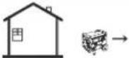 Only use OUTSIDE andfar away from windows,doors, and vents. Only use OUTSIDE andfar away from windows,doors, and vents. | ⚠ PELIGROUsar un generador en el interior PUEDE MATARLO EN POCOS MINUTOS.Los gases de escape del generador contienen monóxido de carbono. Es un venenoque no puede verse ni olerse.NUNCA lo use dentro de su hogar o del garaje, INCLUSO con las puertas y lasventanas abiertas.Sólo utilicelo AL AIRE LIBRE y lejos de ventanas, puertas y respiraderos. |
(California Proposition 65)
WARNING:
The engine exhaust from this product contains chemicals known to the State of California to cause cancer, birth defects or other reproductive harm.
(California only)
AIR INDEX
To show compliance with California emission regulations, a hangtag has been provided displaying the Air Index level and durability period of this engine.
The Air Index level defines how clean an engine's exhaust is over a period of time. A bar graph scaled from "0" (most clean) to "10" (least clean) is used to show an engine's Air Index level. A lower Air Index level represents cleaner exhaust from an engine.
The period of time (in hours) that the Air Index level is measured is known as the durability period. Depending on the size of the engine, a selection of time periods can be used to measure the Air Index level (see below).
Descriptive Term Applicable to Emissions Durability Period
Moderate - 50 hours (engine from 0 to 80 cc) 125 hours (engine greater than 80 cc)
Intermediate - 125 hours (engine from 0 to 80 cc) 250 hours (engine greater than 80 cc)
Extended - 300 hours (engine from 0 to 80 cc) 500 hours (engine greater than 80 cc) 1000 hours (225 cc and greater)
Notice : This hangtag must remain on this engine or piece of equipment, and only be removed by the ultimate purchaser before operation.
Notice : There is permanent conductor between the generator (Stator Winding) and the frame.
Notice : FEDERAL EMISSION COMPONENT DEFECT WARRANTY and CALIFORNIA EMISSION CONTROL WARRANTY are applicable to only those engines/ generators complied with EPA (Environmental Protection Agency) and CARB (California Air Resources Board) emission regulations in the U.S.A.
Notice : To the engines/generators exported to and used in the countries other than the U.S.A., warranty service shall be performed by the distributor in each country in accordance with the standard SUBARU engine/generator warranty policy as applicable.
FOREWORD
Thank you for choosing a SUBARU GENERATOR.
This manual covers operation and maintenance of the SUBARU GENERATORS. All information in this publication is based on the latest production information available at the time of printing.
Keep this owner's manual at hand, so you can refer to it when needed.
Due to constant efforts to improve our products, certain procedures and specifications are subject to change without notice.
When ordering spare parts, always give us the MODEL, PRODUCTION NUMBER and SERIAL NUMBER of your generator.
Please fill in the blanks below after checking the production number on your engine. Below is a sample of what the specification label looks like.
(Location of label is different depending on the engines specification.)

PRODUCT REGISTRATION
Please take a moment to register your product to ensure easy warranty qualification and product updates.
Please register online at: www.SubaruPower.com/register
You will need the following two pieces of information to complete your product registration.

SUBARU Industrial Power Products
905 Telser Road • Lake Zurich, IL 60047 • USA • Toll Free: 800-277-6246 • 847-540-7300
www.subarupower.com
Limited Engine Warranty
(Effective with engines purchased from SUBARU Industrial Power Products, Lake Zurich, IL, after April 1, 2008)
Robin America, Inc. doing business as SUBARU Industrial Power Products, a division of Fuji Heavy Industries, Ltd. (herein "SIP"), warrants that each new engine sold by it will be free, under normal use and service, from defects in material and workmanship for a period listed below from the date of sale to the original retail purchaser. SIP's obligation under this Limited warranty shall be limited to the repair and replacement, at SIP's option, of any part or parts which upon examination is/are found, in SIP's judgment, to have been defective in material or workmanship. It shall be a condition of SIP's obligation under this Limited Warranty that SIP, directly or through one of its Distributors or Service Centers authorized to service the particular engine involved, receive prompt notice of any warranty claim and that the engine or the part or parts claimed to be defective be promptly delivered, transportation prepaid, to such distributor or service Center for inspection and repair. All repairs qualifying under this Limited Warranty must be performed by SIP or one of its authorized Distributors or Service Centers.
WARRANTY PERIODS:
SUBARU Four-Cycle, EX Series Gasoline Engines Limited 5 year Warranty
To Qualify for this Warranty:
SUBARU Engines must be purchased from a SUBARU Industrial Power Products dealer or distributor authorized to sell that product in North America.
The repair or replacement of any part or parts under this Limited Warranty shall not extend the term of the engine warranty beyond the original term as set forth above.
LIMITATIONS AND EXCLUSIONS: This Limited Warranty shall not apply to:
- Bent or broken crankshaft or resultant damage caused by vibration related to a bent or broken crankshaft. Also, damage caused by loose engine mounting bolts or improper or imbalanced accessories or blades mounted to the crankshaft.
- Repairs required because of prolonged storage including damage caused by old or contaminated fuel in the fuel tank, fuel lines or carburetor, sticky valves or corrosion and rust of engine parts.
- Repair required due to overheating. (Most often caused by overloaded or clogged or damaged or missing flywheel, fan, inlet air passages, cooling fins or air shrouds.)
- Dirt or grit related wear caused by improper air cleaner maintenance (most often resulting in worn piston, piston rings, cylinders, valves, valve guides, carburetor or other internal components).
- Broken or scored parts caused by low oil level, dirty or improper grade of oil.
- Engine tune-ups and normal maintenance service including, but not limited to, valve adjustment, normal replacement of service items, fuel and lubricating oil, etc.
- Any engine which has been subject to negligence, misuse, accident, misapplication or over-speeding.
- Any engine that has been installed, repaired, or altered by anyone in a manner which in SIP's sole judgment adversely affects its performance or reliability.
- Any engine which has been fitted with or repaired with parts or components not manufactured or approved by SIP which in SIP's sole judgment adversely affects its performance or reliability.
- Instances when normal use has exhausted the life of a component or an engine.
The customer is responsible for all transportation charges in connection with any warranty work.
SIP reserves the right to modify, alter or improve any engines or parts without incurring any obligation to modify or replace, any engine or parts previously sold without such modification, alternation or improvement.
No person is authorized to give any other warranty or to assume any additional obligation on SIP's behalf unless made in written and signed by an official of SIP.
THIS WARRANTY, AND SIP'S OBLIGATION HERE UNDER, ARE IN LIEU OF ANY OTHER WARRANTIES OR OBLIGATIONS OF ANY KIND, EXPRESSED OR IMPLIED, INCLUDING ANY WARRANTIES OF MERCHANTABILITY OR FITNESS FOR A PARTICULAR PURPOSE. THERE ARE NO WARRANTIES WHICH EXTEND BEYOND THE DESCRIPTION ON THE FACE HERE-OF. SIP SHALL IN NO EVENT BE LIABLE FOR ANY CONSEQUENTIAL OR INCIDENTAL DAMAGES.
Limited Generator Warranty
(Effective with generators purchased from SUBARU Industrial Power Products, Inc., Lake Zurich, IL, after April 1, 2008)
Robin America, Inc. doing business as SUBARU Industrial Power Products, a division of Fuji Heavy Industries, Ltd. (herein "SIP"), warrants that each new generator sold by it will be free, under normal use and service, from defects in material and workmanship for a period listed below from the date of sale to the original retail purchaser. SIP's obligation under this Limited warranty shall be limited to the repair and replacement, at SIP's option, of any part or parts which upon examination is/are found, in SIP's judgment, to have been defective in material or workmanship. It shall be a condition of SIP's obligation under this Limited Warranty that SIP, directly or through one of its Distributors or Service Centers authorized to service the particular engine involved, receive prompt notice of any warranty claim and that the engine or the part or parts claimed to be defective be promptly delivered, transportation prepaid, to such distributor or service Center for inspection and repair. All repairs qualifying under this Limited Warranty must be performed by SIP or one of its authorized Distributors or Service Centers.
WARRANTY PERIODS:
SUBARU Four-Cycle, Air-Cooled, Gasoline Generator Limited 3 year Warranty
To Qualify for this Warranty:
SUBARU Generators must be purchased from a SUBARU Industrial Power Products dealer or distributor authorized to sell that product in North America.
The repair or replacement of any part or parts under this Limited Warranty shall not extend the term of the engine warranty beyond the original term as set forth above.
LIMITATIONS AND EXCLUSIONS: This Limited Warranty shall not apply to:
- Repairs required because of prolonged storage including damage caused by old or contaminated fuel in the fuel tank, fuel lines or carburetor, sticky valves or corrosion and rust of engine parts.
- Repair required due to overheating. (Most often caused by overloaded or clogged or damaged or missing flywheel, fan, inlet air passages, cooling fi ns or air shrouds.)
- Dirt or grit related wear caused by improper air cleaner maintenance (most often resulting in worn piston, piston rings, cylinders, valves, valve guides, carburetor or other internal components).
- Broken or scored parts caused by low oil level, dirty or improper grade of oil.
- Engine tune-ups and normal maintenance service including, but not limited to, valve adjustment, normal replacement of service items, fuel and lubricating oil, etc.
- Any engine/generator that has been installed, repaired, or altered by anyone in a manner which in SIP's sole judgement adversely affects its performance or reliability.
- Any engine/generator which has been fitted with or repaired with parts or components not manufactured or approved by SIP which in SIP's sole judgment adversely affects its performance or reliability.
- Warranty does not extend to parts affected or damaged by accident and/or collision, normal wear, fuel contamination, use in an application for which the product was not designed or any other misuse, neglect, incorporated or use of unsuitable electrical attachments or parts.
- Instances where normal use has exhausted the life of a component.
- In case, without any prior approval of SIP's the generator is employed for powering equipment to be operated on/in water and is located where it gets exposed to water.
The customer is responsible for all transportation charges in connection with any warranty work.
SIP reserves the right to modify, alter or improve any engines or parts without incurring any obligation to modify or replace, any engine/generator or parts previously sold without such modification, alternation or improvement.
No person is authorized to give any other warranty or to assume any additional obligation on SIP's behalf unless made in written and signed by an official of SIP.
For optimum performance and safety, please read the owner's manual before operating your SUBARU generator. Connection to house power requires a transfer device to avoid possible injury to power company personnel. Please consult a qualified electrician.
THIS WARRANTY, AND SIP'S OBLIGATION HERE UNDER, ARE IN LIEU OF ANY OTHER WARRANTIES OR OBLIGATIONS OF ANY KIND, EXPRESSED OR IMPLIED, INCLUDING ANY WARRANTIES OF MERCHANTABILITY OR FITNESS FOR A PARTICULAR PURPOSE. THERE ARE NO WARRANTIES WHICH EXTEND BEYOND THE DESCRIPTION ON THE FACE HERE-OF. SIP SHALL IN NO EVENT BE LIABLE FOR ANY CONSEQUENTIAL OR INCIDENTAL DAMAGES.
WORLD WIDE SUPPORT
SUBARU Engines are supported through a network of dozens of wholesale distributors and thousands of service dealers worldwide. Please use the following contacts to find support nearest you.
Global Distributor Locator: www.subaru-robin.jp/index_e.html
North America:
SUBARU Industrial Power Products, Inc.
905 Telser Road
Lake Zurich, IL 60047 U.S.A.
E-mail: email@crommelins.com.au
Web: www.crommelins.com.au
SYMBOLS

Read Owner's Manual

Stay clear of the hot surface.

Exhaust gas is poisonous. Do not operate in an unventilated room or enclosed area.

Stop the engine before refueling.

Fire, open flame and smoking prohibited.
On

Plus ;
positive polarity

Off

Battery

Engine oil

Engine start
(Electric Start)


Add oil
| USA and CANADA only | |||||
| Read INSTRUCTIONS FOR USE before use. | The engine emits toxic gas can kill you in minutes.Do not run in an enclosed area. | Hot surface can burn you. Stay away if engine has been running. | |||
| Gasoline is extremely flammable and its vapors can explode. Stop the engine before refueling.Check for leakage from hoses and fittings.Shut off fuel valve when the engine is not in use. | |||||
CONTENTS
SAFETY PRECAUTIONS 1
SPECIFICATIONS 4
COMPONENTS 5
ASSEMBLY PROCEDURES 6
Pay special attention to statements preceded by the following words:

DANGER
Indicates a possibility of death or serious injury if instructions are not followed.

WARNING
Indicates a strong possibility of severe personal injury, loss of life and equipment damage if instructions are not followed.
[CAUTION]
Indicates a possibility of personal injury or equipment damage if instructions are not followed.
NOTE:
Gives helpful information.
If a problem should arise, or if you have any questions about the generator, consult an authorized dealer or service shop.

WARNING
- The generator is designed to give safe and dependable service if operated according to instructions.
- Do not operate the generator before you have read and understood the instructions. Failure to do so could result in death, personal injury or equipment damage.
SAFETY PRECAUTIONS
Please make sure you review each precaution carefully.

DANGER
Do not operate the generator indoors, in a garage, carport, basement or other confined space. Opening a garage door does not provide sufficient ventilation to prevent injury or death.
Always operate it in a well-ventilated area, otherwise the engine may become overheated, and the poisonous carbon monoxide gas, an odorless, colorless, poison gas, contained in the exhaust gas will endanger human lives.
Operate generator only outdoors and far from open window, doors, ventilation intakes and other openings.
Keep the generator at least 1 meter (3 feet) away, including overhead, from any structure of building use.


WARNING
Do not operate the generator near gasoline or gaseous fuel because of the potential danger of explosion or fire.
Do not fill the fuel tank with fuel while the engine is running. Do not smoke or use open flame near the fuel tank. Be careful not to spill fuel
during refueling. If fuel is spilled, wipe it off and let dry before starting the engine.


WARNING
Do not place fl ammables near the generator.
Be careful not to place fuel, matches, gunpowder, oily cloths, straw, trash, or any other flammables near the generator.


WARNING
Do not enclose the generator nor cover it with a box.
The generator has a built-in forced air cooling system, and may become overheated if it is enclosed. If generator has been covered to protect it from the weather during non use, be sure to remove it and keep it well away from the area during generator use.


WARNING
Operate the generator on a level surface.
It is not necessary to prepare a special foundation for the generator. However, the generator will vibrate on an irregular surface, so choose a level place without surface irregularities.
If the generator is tilted or moved during operation, fuel may spill and/or the generator may tip over, causing a hazardous situation.
Proper lubrication cannot be expected if the generator is operated on a steep incline or slope. In such a case, piston seizure may occur even if the oil is above the upper level.


WARNING
Pay attention to the wiring or extension cords from the generator to the connected device. If the wire is under the generator or in contact with a vibrating part, it may break and possibly cause a fire, generator burnout or electric shock hazard. Replace damaged or worn cords immediately.


WARNING
Do not operate in rain, wet or damp conditions, or with wet hands. The operator may suffer severe electric shock if the generator is wet due to rain or snow.

WARNING
If wet, wipe and dry it well before starting, Do not pour water directly over the generator, nor wash it with water.
WARNING
Be extremely careful that all necessary electrical grounding procedures are followed during each and every use. Failure to do so can be fatal.
WARNING
Do not connect the generator to a commercial power line. Connection to a commercial power line may short circuit the generator and ruin it or cause electric shock hazard. Use the transfer switch for connecting to domestic circuit.

WARNING
No smoking while handling the battery. The battery emits flammable hydrogen gas, which can explode if exposed to electric arcing or open flame. Keep the area well-ventilated and keep open flanges/sparks away when handling the battery.

WARNING
Engine becomes extremely hot during and for some time after operation. Keep combustible materials well away from generator area. Be very careful not to touch any parts of the hot engine especially the muffler area or serious burns may result.
WARNING
Keep children and all bystander at a safe distance from work areas.

WARNING
It is absolutely essential that you know the safe and proper use of the power tool or appliance that you intend to use. All operators must read, understand and follow the tool/appliance owners manual. Tool and appliance applications and limitations must be understood. Follow all directions given on labels and warnings. Keep all instruction manuals and literature in a safe place for future reference.
WARNING
Use only "LISTED" extension cords. When a tool or appliance is used outdoors, use only extension cords marked "For Outdoor Use". Extension cords, when not in use should be stored in a dry and well ventilated area.
WARNING
Always switch off generator's AC circuit breaker and disconnect tools or appliance when not in use, before servicing, adjusting, or installing accessories and attachments.
WARNING
Make sure the engine is stopped before starting any maintenance, servicing or repair. Make sure maintenance and repair of the generator set are performed by properly trained personnel only.
WARNING
Do not allow drunk driving.
WARNING
Do not use the generator as electric power for medical appliance.
CAUTION
: PRECAUTIONS ON THE HANDLING OF THE WARNING LABEL
Warning labels are affixed to our engines with regard to particularly serious dangers.
When using the engines, please use them safely after carefully reading the instruction manual and understanding the dangers.
Warning Label Exclusively for the United States and Canada


For use in the United States or Canada, please affix the label suited to the region from among the enclosed warning labels.
SPECIFICATIONS
| Model SGX3500 SGX50 | 00 SGX7500 | ||
| Voltage Regulation Automatic | Voltage Regulator (AVR) | ||
| Certification CSA / EPA Phase | 3 / California Tier 3 | ||
| Frequency/Phase 60Hz / Single | Phase | ||
| Voltage 120/240 | |||
| Max Output (watts) 3500 4900 | 7300 | ||
| Max Amps (Amps@120V/240V) | 29.1/14.5 40.8/20 | 0.4 60.8/30.4 | |
| Rated Output (watts) 3200 450 | 0 6700 | ||
| Rated Amps (Amps@120V/240V) | 26.6/13.3 37.5/18 | 8.8 55.8/27.9 | |
| Current Protection Dual pole m | magnetic circuit breaker & GFCI | ||
| Ground systemAC system | Neutral bonded to frame | ||
| Engine (model and HP) EX21, | 7HP EX30, 9.5HP EX40, 14HP | ||
| Type | SUBARU Commercial Overhead Cam gasoline engine | ||
| Low Oil System | Low Oil Shutdown Protection | ||
| Fuel Tank Capacity* Gal.(L) | 3 (11.3) | 6 (22.7) | |
| Run time at 1/2 load (Hours) | 7.8 | 10.8 | 7.7 |
| Run time at rated load (Hours) | 5.8 | 7.9 | 5.2 |
| Starting System | Recoil starter | Electric starter / Recoil | |
| Battery | N/A | Sealed 12 V 18 AHr. | |
| Dimensions LxWxH(inch/ mm)** | 28" x 25" x 26"(702 x 626 x 658)" | 30" x 29" x 29"(763 x 726 x 737) | |
| Dimensions less wheel kitLxWxH (inch/ mm) | 26" x 17" x 21"(661 x 432 x 534)" | 28" x 21" x 24"(712 x 534 x 610) | |
| Dry Weight (lbs/ kg) includeswheel kit | 137 (62) | 177 (80) | 229 (104) |
| GFCI 120V, 20A duplex | 2 | 2 | 2 |
| 120V, 30A Twist lock | N/A | 1 | 1 |
| 120/240V, 30A Twist lock | 1 | 1 | 1 |
| Hour meter | Yes | Yes | Yes |
| Wheel Kit | Yes | Yes | Yes |
Specifications are subject to change without notice.
* Fuel tank capacity measured at a 15 degree incline is as follows: SGX3500 - 3 gal (11.3 L), SGX5000/SGX7500 - 6 gal (22.7 L)
** Include wheel kit and extended handles
COMPONENTS


ASSEMBLY PROCEDURES
UNPACKING
This product requires some assembly.
- Carefully cut the box down the sides then remove the machine and any accessories from the box. Make sure that all items listed in the packing list are included.
| Part name | Qty | Remarks |
| Feet | 2 | |
| Flange bolt | 4 | M8×16 |
| Wheel shaft | 2 | |
| Wheel | 2 | |
| Washer | 2 | 16 × 30 × 3.0 |
| Clip | 2 | 12 × 24 × 1.2 |
| Flange bolt | 8 | M8×16 |
| Flange nut | 8 | M8 |
| Handle | 2 | |
| Spacer | 2 | |
| Nylon washer | 4 | |
| Flange bolt | 2 | M8×50 |
| Handle lock nut | 2 | M8 |
| Handle lock pin | 2 | |
| lanyard | 2 | |
| Accessory tool kit | 1 | Box wrench / wrench handle |
| Switch key | 2 | Electric starter model Only |
NOTE:
This machine is heavy and requires a minimum of two people to lift.
- Inspect the unit carefully to make sure no damage occurred during shipping.
- Do not discard the packing material until you have carefully inspected and satisfactorily operated the product.
- If any parts are damaged or missing, please call your local service center for assistance.
WARNING
Do not use this product if it is not completely assembled or if any parts appear to be missing or damaged. Use of a product that is not properly and completely assembled could result in serious personal injury.
WARNING
Do not attempt to modify this product or create accessories not recommended for use with this product. Any such alteration or modification is misuse and could result in a hazardous condition leading to possible serious personal injury.
NOTE:
Do not put fuel or lubricant in the generator before installing the feet, wheels and handles.
INSTALLING THE FEET ON THE FRAME
Locate the following items:
Feet (2) Flange bolt (2)
Tightening torque: 12 to 19N·m (8.9 to 14ft-lb) (1.2 to 1.9kg·m)
- Insert flange bolt through rubber foot and rubber support, then through frame.
- Thread washer over the flange bolt, then install nut. Tighten nut securely. NOTE: Be careful not to over tighten so that foot material collapses.
- Repeat with remaining foot.

INSTALLING THE WHEELS
Wheels are provided to assist in moving the generator to the desired location and should be installed on the opposite side of the handle.
Locate the following items:
Flange bolt (8)
Flange nut (8)
Washer (4)
Wheel shaft (2)
Wheel (2)
Clip (2)
Tightening torque: 12 to 19N·m (8.9 to 14ft-lb) (1.2 to 1.9kg·m)
- Raise the end of the generator opposite the handle, high enough to gain access to the frame bottom: securely position props underneath to support.
• Install wheel and washer onto wheel shaft and fasten with clip. - Check that the wheel rotates smoothly.
- Align the position of the hole on the frame with the mounting hole of wheel shaft and tighten flange bolt and flange nut to fix this in place.
- Repeat the process on the other side to install second wheel.

ATTACHING THE HANDLE
Locate the following:
Handle (2)
Flange bolt (2)
Spacer (2)
Nylon Washer (4)
Flange nut (2)
Tightening torque: 12 to 19N·m (8.9 to 14ft-lb) (1.2 to 1.9kg·m)
- Place a spacer through the lower holes of one pair of handle mounting brackets on the frame.
- Slide the handle over the pair of mounting brackets.
- Carefully slide both nylon washers between the handle mounting brackets on the frame and the handle bracket so they are on either end the spacer.
- Repeat for the other handle.
- Slid a bolt through the handle brackets, washers and spacer, then install and tighten a flange nut on the flange bolt.

LOCKING THE HANDLE
Locate the following items:
Handle lock pin (2) Lanyard (2)
- Attach the lanyard to the handle lock pin and the handle.
in the handle and the generator frame to secure handle in place.
- Repeat the process on the other side to lock the other handle.

[CAUTION]
Do not attempt to lift the unit by the handle assembly. If it is necessary to lift the generator, always grasp by the frame. Use proper lifting means to avoid back injury.
RELEASING THE HANDLES
Remove the handle lock pins and lower the handles to the down position.

natural_image
Diagram showing a mechanical assembly before and after a change, with no visible text or symbols.CONTROL PANEL


Before checking or refilling oil, be sure generator is located on stable and level surface with engine stopped.
NOTE:
The generator has been shipped from factory without oil in the crankcase. Operating the unit without oil will damage the engine.
- Remove oil gauge (oil fi ller cap) and check the engine oil level.
- If oil level is below the lower level line, refill with suitable oil (see table) to upper level line. Do not screw in the oil gauge (oil filler cap) when checking oil level.
.detaraimoc fi lio egnahC
(See "How-To" Maintenance)
| Oil capacity *Upper level) | Oz. (L) |
| SGX3500 | 20 oz. (0.6 L) |
| SGX5000 | 33 oz. (1.0 L) |
| SGX7500 | 40 oz. (1.2 L) |

Always check engine oil level before every start. For oil, use high-quality API classification oil with grade of SE or higher grade oil according to the table below. SAE 10W-30 or 10W-40 is recommended for general, all-temperature use. If single viscosity oil is used, select the appropriate viscosity for the average temperature in your area.

bar
| Category | Temperature | Ambient Temperature | |---|---|---| | Single Grade | 5W | -20 | | Single Grade | 10W | -1 | | Single Grade | 20W | -10 | | Single Grade | #20 | 0 | | Single Grade | #30 | 10 | | Single Grade | #40 | 20 | | Multigrade | 10W-30 | 30 | | Multigrade | 10W-40 | 40°C | | Ambient Temperature | -1 | -1 | | Ambient Temperature | 14 | 14 | | Ambient Temperature | 32 | 32 | | Ambient Temperature | 50 | 50 | | Ambient Temperature | 68 | 68 | | Ambient Temperature | 86 | 86 | | Ambient Temperature | 104°F | 104°F |CHECK ENGINE FUEL
Check fuel level at fuel level gauge, fill as required. Make sure the generator is turned off and has been allowed time to cool down.
NOTE:
THE ENGINE IS CERTIFIED TO OPERATE ON AUTOMOTIVE UNLEADED GASOLINE.
- Check fuel level at fuel level gauge.
- If fuel level is low, refill with unleaded automotive gasoline.
- Use unleaded automotive gasoline only.
- Unleaded regular/premium or reformulated gasoline containing no more than 10% Ethanol (E10), or 15% MTBE may also be used.
- Never use gasoline containing ethanol exceeding 10%, or MTBE exceeding 15% because engine or fuel system could be damaged.
.enilosag detanimatnoc ro elats esu reve
- Use of these non-recommended fuels may result in reduced performance and/or denial of warranty.
- Stop the engine and open the cap.
- Close the fuel valve before filling the fuel tank.
- Be sure to use the fuel filter screen on the fuel filter neck.
- Fuel level should never over the RED marking at the inlet portion.
- Reattach the fuel cap by turning clockwise until reaching the physical stop (about one quarter turn).
Do not attempt to turn past the physical stop or the fuel cap may be damaged.
Fuel Capacity US Gal.(L)
SGX3500....2.91 gal. (11.0 L)
SGX5000/7500....5.94 gal. (22.5 L)
NOTE: SUBARU recommends the use of Sta-Bil fuel stabilizer at every fill up to keep fuel fresh.
Available at most retailers of outdoor power equipment.


WARNING
- Do not refuel while smoking or near open flame or other such potential fire hazards. Do not mix oil with gasoline. Do not use mixed fuel. Fuel system damage or performance problems caused from the use oxygenated fuel are not covered under warranty.
- Remove the static electricity from your body before refilling the gasoline.
Sparking from electrostatic discharge may cause the ignition to the vaporized fuel (gasoline) resulting burns. Static electricity can be discharged from the body by touching by hand the metal parts of the unit and the fuel dispensing pump.
WARNING
Make sure you review each warning in order to prevent fire hazard.
- Do not refi ll tank while engine is running or hot.
- Be careful not to let dust, dirt, water or other objects into fuel.
- Wipe off spilled fuel thoroughly before starting engine.
- Keep open flames away.
CHECKING COMPONENT PARTS
Check the following items before starting the engine.
• Fuel leakage from fuel hose, etc.
- Bolt and nuts for looseness.
- Components for damage or breakage.
- Generator not resting on or against any adjacent wiring.
CHECK GENERATOR SURROUNDINGS
WARNING
Make sure you review each warning in order to prevent fire hazard.
- Keep area clear of flammables or other hazardous materials.
- Keep generator at least 1 meter (3 feet) away from buildings or other structures.
- Only operate generator in a dry, well ventilated area.
- Keep exhaust pipe clear of other objects.
- Keep generator away from open flame. No smoking!
- Keep generator on a stable and level surface.
- Do not block generator air vents with paper or other material.
BATTERY INSTALLATION (SGX7500 Only)
Recommended Battery
Type: Sealed Lead-acid battery
Capacity (Ah/5hr): 12V-18Ah
Size LxWxH inches(mm): 7.0" x 2.9" x 6.5" (178 x 75 x 167)

WARNING
Death, personal injury and/or property damage may occur unless instructions are followed carefully.
- Use battery of recommended capacity.
- Turn the starter switch to the "OFF" position when mounting or dismounting battery. When mounting battery, connect the positive (+) cable first and then the negative (-) cable to the battery. Be careful not to short battery cables. When dismounting battery, disconnect negative (-) cable first.
RED CABLE : To positive (+) terminal
BLACK CABLE : To negative (-) terminal
- Should the connection be made in an incorrect manner, the generator may be damaged.
- Tighten bolts and nuts on terminals securely so they will not loosen with vibration.
- Disconnect battery cables when charging battery.
GROUNDING THE GENERATOR
• To ground the generator to the earth, connect the ground terminal of the generator to the grounding spike driven into the earth or to the conductor which has been already grounded to the earth.
• Refer to local municipalities for proper codes.


natural_image
Two technical symbols: a hexagonal nut and a standard electrical symbol (no text or labels)OPERATING PROCEDURES
STARTING THE GENERATOR
[CAUTION]
Check the oil level before each operation as outlined in "CHECK ENGINE OIL".
A. Turn the engine switch to the "ON" position.
Recoil starter model

B. Turn the circuit breaker to the "OFF" position

NOTE:
This type of circuit breaker cannot make "OFF" by manual operation.

C. Open the fuel valve and set the choke lever to the "START" position.

D. [Recoil Starter model]
Pull the starter handle slowly until passing the compression point (resistance will be felt), then return the handle to its original position and pull briskly.
- If the engine fails to start after several attempts, repeat above procedures with the choke lever in the "RUN" position.
- Do not fully pull out the rope.
• After starting, allow the starter handle to return to its original position while still holding the handle.
E. [Electric Start model]
Insert the key into the key switch and turn it clockwise to the "START" position to start the engine.
[CAUTION]
If the engine fails to start, return the key to the "ON" position and wait about 10 seconds then start again.
- Do not turn the key switch to "START" when the engine is running to prevent damage to the starting motor.
- When starting the engine by recoil starter, set the key switch at the "ON" position and pull the starter handle.
F. Allow the engine to run for 30 seconds, then move the choke to the "RUN" position.
G. Warm up the engine without a load for a few minutes.
OIL SENSOR
- All generator models include a low oil level sensor designed to shut the engine off if the engine oil level is below the safe operation range.
- If the engine oil level is low during start up the engine will not start or will start briefly and then shut off.
- If the engine oil level becomes low during operation, the engine.
- If the engine stops during operation, check the oil level and fill as instructed on page 10, "Check Oil Level" section.
- You may also need to check the fuel level as instructed on page 11, "Check Engine Fuel" section.
• Always check the oil level before starting the engine as instructed on page 10.

USING ELECTRIC POWER
WARNING
- Make sure that the appliance is switched OFF before connecting it to the generator.
- Do not move the generator while it is running.
A. Check the voltage requirements of the appliance. Be sure to plug the appliance into the correct outlet to ensure proper voltage supply.
B. Turn off the switch/switches of the electrical appliance before connecting to the generator.
C. Insert the plug of the electrical appliance into the receptacle.
- Check the amperage of the receptacles used referring to the following table, and be sure not to take a current exceeding the specified amperage.
- Be sure that the total wattage of all appliances does not exceed the rated output of the generator.
D. Turn on the switch of the appliance.
| Style | Ampere | Receptacle | AC plug | Description | |
 | up to 20A | NEMA5-20R | NEMA5-20P | GFCI (Ground Fault Circuit Interrupter) Receptacle, duplex | |
 | up to 30A | NEMAL5-30R | NEMAL5-30P | Locking Receptacle | |
 | up to 30A | NEMAL14-30R | NEMAL14-30P | Locking Receptacle | |
WARNING
- To take power out from the TWIST LOCK RECEPTACLE, insert the plug into the receptacle, and turn it clockwise to the lock position.
- Be sure to ground the generator if the connected electrical device is grounded

NOTE:
When the circuit breaker turns off during operation, the circuit is over loaded or the appliance is defective.
Stop the generator immediately, turn off the appliance, check the appliance, check the extension cord and/or generator for overloading or defect and have repaired as necessary by a qualified technician.
[CAUTION]
The duplex 120V receptacle is protected by a GFCI (Ground Fault Circuit Interrupter). GFCI shuts off the output current from the duplex 120V receptacle when a ground fault occurs in the generator or the appliance. Please note that other receptacles are not protected by GFCI.
E. Turn the circuit breaker to the "ON" position.
F. Turn on the switch of the appliance.

This generator provides two independent 120V power circuits, and each circuit is protected against overload by a magnetic circuit breaker. Circuit 1 is available via one 120V GFCI duplex receptacle (two actual outlets). Up to 15A may be drawn through one or both outlets on the receptacle, independent of any loads on circuit 2.
Circuit 2 is available via a 3-prong 120V locking receptacle*. Up to 15A may be drawn through this circuit independent of any loads on circuit 1.
A 4-prong 120/240V locking receptacle** is also provided. Circuits 1 & 2 are both available via this receptacle, as is a single 240V circuit.
SGX5000 / SGX7500 Operation:
This generator provides two independent 120V power circuits, and each circuit is protected against overload by a magnetic circuit breaker. Circuit 1 is available via one 120V GFCI duplex receptacle (two actual outlets). Up to 20A may be drawn through one or both outlets on the receptacle, independent of any loads on circuit 2.
Circuit 2 is available via a 2nd GFCI Duplex receptacle and a 3-prong 120V locking receptacle*. Up to 20A may be drawn through this circuit independent of any loads on circuit 1.
A 4-prong 120/240V locking receptacle** is also provided. Circuits 1 & 2 are both available via this receptacle, as is a single 240V circuit.
*This NEMA L5-30R receptacle requires a custom cordset – parts can purchased at any local home center or hardware store. Or a pre-made cordset is available from SUBARU that converts this receptacle to work with ordinary 120V plugs.
** This NEMA L14-30R receptacle requires a custom cordset – parts can purchased at any local home center or hardware store. It is typically used for connecting the generator to the home service panel. You must consult a licensed electrician and use a double pole transfer switch when connecting a generator to your home service panel.
If a circuit breaker trips due to excessive load, try to balance the load by moving cords from the most heavily loaded circuit to the more lightly loaded circuit. If the circuit breaker continues to trip, you are exceeding the capacity of the generator.

CONNECTING TO A BUILDINGS ELECTRICAL SYSTEM
Connection to a building's electrical system must be performed by a qualified electrician. The generator power must be isolated from utility power and must adhere to all local codes and ordinances. Note that a double-throw transfer switch must be installed by a qualified electrician to properly isolate the generator from the utility service.
Improper connection to a building's electrical system can result in back feeding of power through the utility power lines. This presents an electrocution hazard for line workers and others that may come into contact with these lines during an outage. Improper connection can also result in damage to the generator once power is restored. Consult your local utility company or a qualified electrician.
GFCI RECEPTACLE
After starting the engine, check the GFCI for proper functioning by the following test procedure.
- Push the TEST button. The RESET button will pop out exposing the word TRIP.
Power is now off at the outlets protected by the GFCI, indicating that the device is functioning properly. - If TRIP does not appear when testing, do not use the generator. Call a qualified electrician.
.nottub TEREht hsup ,rewop erotser oT•

WARNING
If the RESET button pops out during operation, stop the generator immediately and call a qualified electrician for checking generator and the appliances.
STOPPING THE GENERATOR
To stop the engine under normal operating conditions:
A. Disconnect any appliance from the generator.
B. Turn the Circuit breaker to the "OFF" position.
C. [Recoil Starter model]
Turn the engine switch to the "OFF" position.
[Electric Start model]
Turn the key switch to the "OFF" position
D. Turn the fuel valve to the "CLOSE" position.


WATTAGE INFORMATION
Some appliances need a "surge" of energy when starting.
This means that the amount of electrical power needed to start the appliance may exceed the amount needed to maintain its use.
Electrical appliances and tools normally come with a label indicating voltage, cycles / Hz, amperage (amps) and electrical power needed to run the appliance or tool.
Check with your nearest SUBARU Industrial Power Products dealer or service center with questions regarding power surge of certain appliances or power tools.
- Electrical loads such as incandescent lamps and hot plates require the same wattage to start as is needed to maintain use.
- Loads such as fluorescent lamps require 1.2 to 2 times the indicated wattage during start-up.
- Loads for mercury lamps require 2 to 3 times the indicated wattage during start-up.
- Electrical motors require a large starting current. Power requirements depend on the type of motor and its use. Once enough “surge” is attained to start the motor, the appliance will require only 50% to 30% of the wattage to continue running.
- Most electric tools require 1.2 to 3 times their wattage for running under load during use. For example, a 5,000 watt generator can power a 1800 to 4000 watt electrical tool.
- Loads such as submersible pumps and air compressors require a very large force to start. They need 3 to 5 times the normal running wattage in order to start.
For example, a 5,000 watt generator would only be able to drive a 1,000 to 1,700 watt pump.
NOTE:
The following wattage chart is general guide only. Refer to your specific appliance for correct wattage.
To determine the total wattage required to run a particular electrical appliance or tool, multiply the voltage figure of the appliance/tool by the amperage (amps) figure of same. The voltage and amperage (amps) information can be found on a name plate which normally attached to electrical appliances and tools.
| Applications | Applicable Wattage(W) | ||
| SGX3500 | SGX5000 | SGX7500 | |
| Incandescent lamp, Heater | 3200 | 4500 | 6700 |
| Fluorescent lamp, Electric tool | 1750 | 2500 | 3700 |
| Mercury lamp | 1250 | 1800 | 2650 |
| Pump, Compressor | 800 | 1100 | 1650 |
VOLTAGE DROP IN ELECTRIC EXTENSION CORDS
When a long electric extension cord is used to connect an appliance or tool to the generator, a certain amount of voltage drop or loss occurs in the extension cord which reduces the effective voltage available for the appliance or tool.
Use the shortest extension cord possible.
| Nominal cross section | A.W.G. | Allowable current | No.of strands / strands dia. | Resistance | Current Amp. | |||||||
| mm^2 | No. A No./mm Ω/100m 1A 3A 5A 8A | 10A 12A 15A | Voltage drop | |||||||||
| 0.75 | 18 | 7 | 30/0.18 | 2.477 | 2.5V | 8V | 12.5V | — | — | — | — | |
| 1.27 | 16 | 12 | 50/0.16 | 1.486 | 1.5V | 5V | 7.5V | 12V | 15V | 18V | — | |
| 2.0 | 14 | 17 | 37/0.26 | 0.952 | 1V | 3V | 5V | 8V | 10V | 12V | 15V | |
| 3.5 | 12 to 10 | 23 | 45/0.32 | 0.517 | — | 1.5V | 2.5V | 4V | 5V | 6.5V | 7.5V | |
| 5.5 | 10 to 8 | 35 | 70/0.32 | 0.332 | — | 1V | 2V | 2.5V | 3.5V | 4V | 5V | |
SPARK ARRESTER
In a dry or wooded area, it is recommendable to use the product with a spark arrester. Some areas require the use of a spark arrester. Please check your local laws and regulations before operating your product.
The spark arrester must be cleaned regularly to keep it functioning as designed.
A clogged spark arrester:
• Prevents the flow of exhaust gas
- Reduces engine output
• Increases fuel consumption
• Make starting difficult
[CAUTION]
If the engine has been running, the muffler and the spark arrester will be very hot. Allow the muffler to cool before cleaning the spark arrester.
How to service the spark arrester
A. Remove the four flange bolts from the muffler cover and remove the muffler cover.
B. Remove the screw from the spark arrester and remove the spark arrester from the muffler.
Clean the spark arrester screen
arrester screen.
- Be careful to avoid damaging the screen.
• The spark arrester must be free of breaks and holes.
- Replace the spark arrester if it is damaged.
• Install the spark arrester, in the reverse order of disassembly.

SPARK ARESSTER SCREEN
kraps eht morf stisoped nobrac evomer pt hsurb a ds•

natural_image
Line drawing of two hands using a tool to cut a textured object (no text or symbols)- Please have an authorized SUBARU Industrial Power Products dealer modify this engine if it is to be run continuously above 5000 feet (1500 meters). Failure to do so, may result in poor engine performance, spark plug fouling, hard starting, and increased emissions.
• Carburetor modification by an authorized SUBARU Industrial Power Products dealer will improve performance and allow this engine to meet EPA (Environmental Protection Agency) and CARB (California Air Resources Board) emission standards throughout its useful life.
- An engine converted for high altitudes can not be run at 5000 feet or lower. In doing so, the engine will overheat and cause serious damage.
Please have an authorized SUBARU Industrial Power Products dealer restore high altitude modified engines to the original factory specification before operating below 5000 feet.
The chart below lists both the standard jet and high altitude jet sizes and SUBARU part numbers
| Generator Model | Engine Model | Standard Jet Size | High Altitude Kit | High Altitude Jet Size |
| SGX3500 | EX21 | #85 | 278-62551-07 | #82.5 |
| SGX5000 | EX30 | #92.5 | 291-62552-07 | #87.5 |
| SGX7500 | EX40 | #113 | 20B-62551-07 | #105 |
MAINTENANCE SCHEDULE
DAILY INSPECTION
Before running the generator, check the following service items:
- Check fuel level
- Check engine oil level and condition
- Loose or broken bolts and nuts
- Leakage of gasoline or engine oil
- Safe surroundings
- Clean air cleaner element

natural_image
Technical line drawings of two portable gas pumps with visible internal components (no text or symbols)PERIODIC MAINTENANCE
Periodic maintenance is vital to safe and efficient operation of your generator. Check the table below for periodic maintenance intervals.
The maintenance schedule indicated in the table is based on the normal generator operation. Should the generator be operated in extremely dusty condition or in heavier loading condition, the maintenance intervals must be shortened depending on the contamination of oil, clogging of filter elements, wear of parts, and so on.
| Maintenance items | Every 8 hours (Daily) | Every 50 hours (Weekly) | Every 200 hours (Monthly) | Every 500 hours | Every 1000 hours |
| Clean generator and check bolts and nuts • (Daily) | |||||
| Check for leakage from hoses and fitting • (Daily) | |||||
| Check and refill engine oil • (Refill daily up to upper level) | |||||
| Change engine oil (*Note 1) • | (Initial 20 hours) | • (Every 100 hours) | |||
| Clean spark plug | • (Every 100 hours) | ||||
| Clean air cleaner | • | ||||
| Clean spark arrester | • (Every 100 hours) | ||||
| Replace air cleaner element | • | ||||
| Clean fuel filter | • | ||||
| Clean and adjust spark plug and electrodes | • | ||||
| Replace spark plug | • | ||||
| Remove carbon from cylinder head (*Note 2) | • | ||||
| Check and adjust valve clearance (*Note 2) | • | ||||
| Clean and adjust carburetor (*Note 2) | • | ||||
| Check and replace carbon brushes | • | ||||
| Replace fuel lines | • (Every 2 years) | ||||
| Overhaul engine (*Note 2) | • | ||||
| Check AC receptacles | • (Daily) | ||||
| ofEngine switch | • (Daily) | ||||
| Replace engine mount | • | ||||
*Note 1: Initial oil change should be performed after first twenty (20) hours of operation.
There after change oil every hundred (100) hours.
Before change oil, check for a suitable way to dispose of old oil.
Do not pour down into sewage drains, onto garden soil or into open streams. Your local zoning or environmental regulations will give you more detailed instructions on proper disposal.
*Note 2: As to the procedures for these items, please refer to the SERVICE MANUAL or consult your nearest service dealer.
"HOW TO" MAINTENANCE
ENGINE OIL CHANGE
.sruoh 001 yreve lio enigne egnahC
(For new engine, change oil after 20 hours)
a) Drain oil by removing the drain plug and the oil gauge (oil filler cap) while the engine is warm.
the oil can be completely drained.
c) Check the oil drain plug, gasket, oil gauge (oil filler cap) and o ring. If damaged, replace.
d) Reinstall the drain plug and fill the engine with oil until it reaches the upper level on the oil gauge (oil filler cap).

WARNING
Be sure that no other material enters the crankcase
- Use fresh high quality lubricating oil to the specified level. If contaminated or deteriorated oil is used or the quantity of the engine oil is not sufficient, engine will be damaged and the engines life will be greatly shortened.
SERVICING THE AIR CLEANER
- Maintaining an air cleaner system in proper condition is very important. Dirt induced through improperly installed, improperly serviced or inadequate elements damages and wears out engines. Always keep the element clean.
A. Urethane Foam Element Type (SGX3500 / SGX5000)
(a) Remove the bolt of air cleaner cover. Remove the air cleaner cover and cleaner element.
(b) Remove the element and wash it in washing oil (kerosene). Then saturate it in engine oil and squeeze it firmly before installing.
B. Dual Element Type (SGX7500)
(a) Remove the bolt of air cleaner cover. Remove the air cleaner cover and cleaner element.
(b) Wash the first element (urethane foam) thoroughly with detergent. Then dry it before installing.
(c) Clean the second element (paper element) by blowing on it with compressed air from the inside or tapping on it gently to remove dirt. Change the paper element when doing this fails to remove the dirt.


WARNING
Never run the engine without the air filter.
NOTE:
Clean and replace air cleaner elements more often when operating in dusty environments. Replace the element if dirt or dust can not be removed and/or that the element is deformed or deteriorated.
CLEANING AND ADJUSTING SPARK PLUG
a) If the plug is contaminated with carbon, remove it using a plug cleaner or wire brush.
b) Adjust the electrode gap to 0.6 to 0.7mm (0.024 to 0.028in).
Recommended Spark Plug : E6RC (TORCH) or BR-6HS (NGK)

CLEANING THE FUEL STRAINER
WARNING
Remove the static electricity from your body before refilling the gasoline. Sparking from electrostatic discharge may cause the ignition to the vaporized fuel (gasoline) resulting burns. Static electricity can be discharged from the body by touching the metal parts of the unit by hand.
Dirt and water in the fuel are removed by the fuel strainer.
a) Remove the strainer cup and trow away water and dirt.
b) Clean the screen and strainer cup with gasoline.
c) Tightly fasten the cup to main body, making sure to avoid fuel leak.

CHECKING CARBON BRUSH
The brush is the area which touches the slip ring, and its surface must be kept smooth.
- If the brush becomes excessively worn, its contact pressure with the slip ring changes and causes a roughened surface on the slip ring, resulting in irregular generator performance.
- Check the brush every 300 hours or if generator performance is irregular.
- If the brush is 0.2 in (5mm) long or less, replace it with a new one.
a) Turn engine off and disconnect spark plug
b) Remove the brush cover
c) Disconnect the wire connector and remove the brush.
d) Carefully note the brush direction and relative position with the slip ring when installing new brush.

BRUSH MAINTENANCE ESSENTIAL (DISASSEMBLY AND ASSEMBLY)
Disassembly
1 Remove the two flange bolts then remove the bracket cover.
2 Remove the two flange bolts then remove the brush.

Assembly
it with the two flange bolts.
When doing so, confirm that the brush is in the proper position relative to the slip ring.
2 Secure the bracket cover by tightening it with the two flange bolts.

gninethgit yb ti eruces gnir pils eht tsniaga hsurb eht gnisserp w1
PREPARATION FOR STORAGE
The following procedures should be followed prior to storage of your generator for periods of 6 months or longer.
WARNING
-
Remove the static electricity from your body before refilling the gasoline. Sparking from electrostatic discharge may cause the ignition to the vaporized fuel (gasoline) resulting burns. Static electricity can be discharged from the body by touching the metal parts of the unit by hand.
• Always store/carry the fuel (gasoline) with metallic portable tank to prevent fire. -
Drain fuel from fuel tank carefully by disconnecting the fuel line.
Gasoline left in the fuel tank will eventually deteriorate making engine starting difficult. - Remove the carburetor float chamber screw and also drain the carburetor.
- Change engine oil.
- Check for loose bolts and screws, tighten them if necessary.
- Clean generator thoroughly with soft cloth. NEVER USE A POWER WASHER TO CLEAN GENERATOR!
- Pull starter handle until resistance is felt, leaving handle in that position.
- Store generator in a well ventilated, low humidity area.

TROUBLESHOOTING
When generator's engine fails to start after several attempts, or if no electricity is available at the output socket, check the following chart. If your generator still fails to start or generate electricity, contact your nearest SUBARU Industrial Power Products dealer or service center for further information or corrective procedures.
When Engine Fails to Start:

flowchart
graph TD
    A["Check if choke lever is in its proper position"] --> B["Check if fuel valve is open If closed, open fuel valve"]
    B --> C["Check fuel level"]
    C --> D["Check if engine switch is OFF Turn engine switch to ON"]
    D --> E["Check to make sure generator is not connected to an appliance"]
    E --> F["Check spark plug for loose spark plug cap If loose, push spark plug"]
    F --> G["Check spark plug for contamination. Remove spark plug and clean electrode."]
    B --> H["Set the choke lever to "START" position - See "Operating Procedures""]
    H --> I["If empty, refill fuel tank making sure not to overfill"]
    I --> J["If connected, turn off the power switch on the connected appliance and unplug"]
    J --> K["cap back into place"]
When No Electricity Is Generated at Receptacle:

flowchart
graph TD
A["Check to make sure magnetic breaker is in the "ON" position"] <--> B["After making sure that the total wattage of the electrical appliance is within permissible limits and there are no defects in the appliance, turn the magnetic breaker to the "ON" position. If breakers continue to actuate, consult your nearest servicing dealer."]
C["Check AC terminals for loose connection Secure connection if necessary"] --> D["Turn off switch on the appliance, and disconnect cable from receptacle. Reconnect after generator has been started properly."]
E["Check to see if engine starting was attempted with appliances already connected to the generator"] <--> F["Low power Carbon brushes are excessively worn."]
WIRING DIAGRAM
"THERE IS A PERMANENT CONDUCTOR BETWEEN THE GENERATOR (STATOR WINDING) AND THE FRAME"
SGX3500 (60Hz-120/240V)

flowchart
graph TD
    subgraph Generator
        A["Generator"] --> B["Control Panel Engine"]
        B --> C["Engine switch"]
        C --> D["Control Panel"]
    end

    subgraph Control Panel
        E["Control Panel Engine"] --> F["Control Panel"]
        F --> G["Control Panel"]
    end

    subgraph Control Panel
        H["Control Panel Engine"] --> I["Control Panel"]
    end

    subgraph Control Panel
        J["Control Panel Engine"] --> K["Control Panel"]
    end

    subgraph Control Panel
        L["Control Panel Engine"] --> M["Control Panel"]
    end

    subgraph Control Panel
        N["Control Panel Engine"] --> O["Control Panel"]
    end

    subgraph Control Panel
        P["Control Panel Engine"] --> Q["Control Panel"]
    end

    subgraph Control Panel
        R["Control Panel Engine"] --> S["Control Panel"]
    end

    subgraph Control Panel
        T["Control Panel Engine"] --> U["Control Panel"]
    end

    subgraph Control Panel
        V["Control Panel Engine"] --> W["Control Panel"]
    end

    subgraph Control Panel
        X["Control Panel Engine"] --> Y["Control Panel"]
    end

    subgraph Control Panel
        Z["Control Panel Engine"] --> AA["Control Panel"]
    end

    subgraph Control Panel
        AB["Control Panel Engine"] --> AC["Control Panel"]
    end

    subgraph Control Panel
        AD["Control Panel Engine"] --> AE["Control Panel"]
    end

    subgraph Control Panel
        AF["Control Panel Engine"] --> AG["Control Panel"]
    end

    subgraph Control Panel
        AH["Control Panel Engine"] --> AI["Control Panel"]
    end

    subgraph Control Panel
        AJ["Control Panel Engine"] --> AK["Control Panel"]
    end

    subgraph Control Panel
        AL["Control Panel Engine"] --> AM["Control Panel"]
    end

    subgraph Control Panel
        AN["Control Panel Engine"] --> AO["Control Panel"]
    end

    subgraph Control Panel
        AP["Control Panel Engine"] --> AQ["Control Panel"]
    end

    subgraph Control Panel
        AR["Control Panel Engine"] --> AS["Control Panel"]
    end

    subgraph Control Panel
        AT["Control Panel Engine"] --> AU["Control Panel"]
    end

    subgraph Control Panel
        AV["Control Panel Engine"] --> AW["Control Panel"]
    end

    subgraph Control Panel
        AX["Control Panel Engine"] --> AY["Control Panel"]
    end

    subgraph Control Panel
        AZ["Control Panel Engine"] --> BA["Control Panel"]
    end

    subgraph Control Panel
        BB["Control Panel Engine"] --> BC["Control Panel"]
    end

    subgraph Control Panel
        BD["Control Panel Engine"] --> BE["Control Panel"]
    end

    subgraph Control Panel
        BF["Control Panel Engine"] --> BG["Control Panel"]
    end

    subgraph Control Panel
        BH["Control Panel Engine"] --> BI["Control Panel"]
    end

    subgraph Control Panel
        BJ["Control Panel Engine"] --> BK["Control Panel"]
    end

    subgraph Control Panel
        BL["Control Panel Engine"] --> BM["Control Panel"]
    end

    subgraph Control Panel
        BN["Control Panel Engine"] --> BO["Control Panel"]
    end

    subgraph Control Panel
        BP["Control Panel Engine"] --> BQ["Control Panel"]
    end

    subgraph Control Panel
        BR["Control Panel Engine"] --> BS["Control Panel"]
    end

    subgraph Control Panel
        BT["Control Panel Engine"] --> BU["Control Panel"]
    end

    subgraph Control Panel
        BV["Control Panel Engine"] --> BW["Control Panel"]
    end

    subgraph Control Panel
        BX["Control Panel Engine"] --> BY["Control Panel"]
    end

    subgraph Control Panel
        BZ["Control Panel Engine"] --> CA["Control Panel"]
    end

    subgraph Control Panel
        CB["Control Panel Engine"] --> CC["Control Panel"]
    end

    subgraph Control Panel
        CD["Control Panel Engine"] --> CE["Control Panel"]
    end

    subgraph Control Panel
        CF["Control Panel Engine"] --> CG["Control Panel"]
    end

    subgraph Control Panel
        CH["Control Panel Engine"] --> CI["Control Panel"]
    end

    subgraph Control Panel
        CJ["Control Panel Engine"] --> CK["Control Panel"]
    end

    subgraph Control Panel
        CR["Control Panel Engine"] --> CS["Control Panel"]
    end

    subgraph Control Panel
        CT["Control Panel Engine"] --> CU["Control Panel"]
    end

    subgraph Control Panel
        CU1[Blm/W: Brown/White: Brown/White: Grey: White/Black: Green/Y: Green/Yellow: Purple: White/White: Purple: White/White: Purple: White/White: Purple: White/White: Purple: White/White: Purple: White/White: Purple: White/White: Purple: White/White: Purple: White/White: Purple: White/White: Purple: White/White: Purple: White/White: Purple: White/White: Purple: White/White: Purple: White/White: Purple: White/White: Purple: White/White: Purple: Black/White/Blue/Green/Green/Green/White/Purple/Purple/Purple/Purple/Purple/Purple/Purple/Purple/Purple/Purple/Purple/Purple/Purple/Purple/Purple/Purple/Purple/Purple/Purple/Purple/Purple/Purple/Purple/Purple/Purple/Purple/Purple/Purple/Purple/Purple/Purple/Purple/Purple/Purple/Purple/Purple/Purple/Purple/Purple/Purple/Purple/Purple/Purple/Purple/Purple/Purple/Purple/Purple/Purple/Purple/PPurple/Purple/Purple/Purple/Purple/Purple/Purple/Purple/Purple/Purple/Purple/Purple/Purple/Purple/Purple/Purple/Purple/Purple/Purple/Purple/Purple/Purple/Purple/Purple/Purple/Purple/Purple/Purple/Purple/Purple/Purple/Purple/Purple/Purple/Purple/Purple/Purple/Purple/Purple/Purple/Purple/Purple/Purple/Purple/Purple/Purple/Purple/Purple/Purple/Purple/Purea / Yellow / White / Black / Blue / Light Blue / Green / White / Red / White / Purple / Purple / Purple / White / White / White / White / White / White / White / White / White / White / White / White / White / White / White / White / White / White / White / White / White / White / White / White / White / White / White / White / White / White / White / White / White / White / White / White / White / White / White / White / White / White / White / White / White / White / White / White / White / White / Black/White/Black/Blue/Green/Green/Green/White/Green/Green/Green/White/Green/Green/Green/White/Green/Green/Green/White/Green/Green/Green/White/Green/Green/Green/White/Green/Green/Green/White/Green/Green/Green/White/Green/Green/Green/White/Green/Green/Green/White/Green/Green/Green/White/Green/Green/Green/White/Green/Green/Green/White/Green/Ggreen/Green/Green/Green/Green/Green/Green/Green/Green/Green/Green/Green/Green/Green/Green/Green/Green/Green/Green/Green/Green/Green/Green/Green/Green/Green/Green/Green/Green/Green/Green/Green/Green/Green/Green/Green/Green/Green/Green/Green/Green/Green/Green/Green/Green/Green/Green/Green/Green/Green/Green/Ggreen/Green/Green/Green/Green/Green/Green/Green/Green/Green/Green/Green/Green/Green/Green/Green/Green/Green/Green/Green/Green/Green/Green/Green/Green/Green/Green/Green/Green/Green/Green/Green/Green/Green/Green/Green/Green/Green/Green/Green/Green/Green/Green/Green/Green/Green/Green/Green/Ggreen/Green/Ggreen/Green/Green/Green/Green/Green/Anterine/Bulk/Bulk/Bulk/Bulk/Bulk/Bulk/Bulk/Bulk/Bulk/Bulk/Bulk/Bulk/Bulk/Bulk/Bulk/Bulk/Bulk/Bulk/Bulk/Bulk/Bulk/Bulk/Bulk/Bulk/Bulk/Bulk/Bulk/Bulk/Bulk/Bulk/Bulk/Bulk/Bulk/Bulk/Bulk/Bulk/Bulk/Bulk/Bulk/Bulk/Bulk/Bulk/Bulk/Bulk/Bulk/Bulk/Bulk/Bulk/Bulk/Bulk/Bunk/Bm/Bm/Bm/Bm/Bm/Bm/Bm/Bm/Bm/Bm/Bm/Bm/Bm/Bm/Bm/Bm/Bm/Bm/Bm/Bm/Bm/Bm/Bm/Bm/Bm/Bm/Bm/Bm/Bm/Bm/Bm/Bm/Bm/Bm/Bm/Bm/Bm/Bm/Bm/BmBmBmBmBmBmBmBmBmBmBmBmBmBmBmBmBmBmBmBmBmBmBmBmBmBmBmBmBmBmBmBmBmBmBmBmBmBmBmBmBmBmBmBmBmBmBmBmBmBmBmCnCnCnCnCnCnCnCnCnCnCnCnCnCnCnCnCnCnCnCnCnCnCnCnCnCnCnCnCnCnCnCnCnCnCnCnCnCnCnCnCnCnCnCnCnCnCnCnCnCnCtHrRtRtRtRtRtRtRtRtRtRtRtRtRtRtRtRtRtRtRtRtRtRtRtRtRtRtRtRtRtRtRtRtRtRtRtRtRtRtRtRtRtRtRtRtRtRtRtRtRtRtRitRitRitRitRitRitRitRitRitRitRitRitRitRitRitRitRitRitRitRitRitRitRitRitRitRitRitRitRitRitRitRitRitRitRitRitRitRitRitRitRitRitRitRitRitRitRitRitRitRitRitrHrTyrHrTyrHrTyrHrTyrHrTyrHrTyrHrTyrHrTyrHrTyrHrTyrHrTyrHrTyrHrTyrHrTyrHrTyrHrTyrHrTyrHrTyrHrTyrHrTyrHrTyrHrTyrHrTyrHrTyrHrTyrHrTvrHrTvrHrTvrHrTvrHrTvrHrTvrHrTvrHrTvrHrTvrHrTvrHrTvrHrTvrHrTvrHrTvrHrTvrHrTvrHrTvrHrTvrHrTvrHrTvrHrTvrHrTvrHrTvrHrTvrHrTvrHrTveHrTveHrTveHrTveHrTveHrTveHrTveHrTveHrTveHrTveHrTveHrTveHrTveHrTveHrTveHrTveHrTveHrTveHrTveHrTveHrTveHrTveHrTveHrTveHrTveHrTvHvHvHvHvHvHvHvHvHvHvHvHvHvHvHvHvHvHvHvHvHvHvHvHvHvHvHvHvHvHvHvHvHvHvHvHv Hv Hv Hv Hv Hv Hv Hv Hv Hv Hv Hv Hv Hv Hv Hv Hv Hv Hv Hv Hv Hv Hv Hv Hv Hv Hv Hv Hv Hv Hv Hv Hw Hw Hw Hw Hw Hw Hw Hw Hw Hw Hw Hw Hw Hw Hw Hw Hw Hw Hw Hw Hw Hw Hw Hw Hw Hw Hw Hw Hw Hw Hw Hw Hw Hw Hw Hw Hw Hw Hw Hw Hw Hw Hw Hw Hw Hw Hw Hw Hw Hw Hwa/Hwa/Hwa/Hwa/Hwa/Hwa/Hwa/Hwa/Hwa/Hwa/Hwa/Hwa/Hwa/Hwa/Hwa/Hwa/Hwa/Hwa/Hwa/Hwa/Hwa/Hwa/Hwa/Hwa/Hwa/Hwa/Hwa/Hwa/Hwa/Hwa/Hwa/Hwa/Hwa/Hwa/Hwa/Hwa/Hwa/Hwa/Hwa/Hwa/Hwa/Hwa/Hwa/Hwa/Hwa/Hwa/Hwa/Hwa/Hwa/Hwa/Hwa/LoAeAeAeAeAeAeAeAeAeAeAeAeAeAeAeAeAeAeAeAeAeAeAeAeAeAeAeAeAeAeAeAeAeAeAeAeAeAeAeAeAeAeAeAeAeAeAeAeAeAeAeqEaEqEaEqEaEqEaEqEaEqEaEqEaEqEaEqEaEqEaEqEaEqEaEqEaEqEaEqEaEqEaEqEaEqEaEqEaEqEaEqEaEqEaEqEaEqEaEqEaEqEaEqEaEqEaEqEaEqEaEqEaEqEaEqEaEqEaEqEAeqEAeqEAeqEAeqEAeqEAeqEAeqEAeqEAeqEAeqEAeqEAeqEAeqEAeqEAeqEAeqEAeqEAeqEAeqEAeqEAeqEAeqEAeqEAeqEAeqEAeqEAeqEAeqEAeqEAeqEAeqEAeqEAeqEAeqEAeqEAeqEAeqEAeqEAeqEAeqEAeqEAeqEAeqEAeqEAeqEAeqEAeqEAeqEAeqEAeqEAqEAeqEAeqEAeqEAeqEAeqEAeqEAeqEAeqEAeqEAeqEAeqEAeqEAeqEAeqEAeqEAeqEAeqEAeqEAeqEAeqEAeqEAeqEAeqEAeqEAeqEAeqEAeqEAeqEAeqEAeqEAeqEAeqEAeqEAeqEAeqEAeqEAeqEAeqEAeqEAeqEAeqEAeqEAeqEAeqEAeqEAeqEAeqEAeqEAeqEAreqEAeqEAeqEAeqEAeqEAeqEAeqEAeqEAeqEAeqEAeqEAeqEAeqEAeqEAeqEAeqEAeqEAeqEAeqEAeqEAeqEAeqEAeqEAeqEAeqEAeqEAeqEAeqEAeqEAeqEAeqEAeqEAeqEAeqEAeqEAeqEAeqEAeqEAeqEAeqEAeqEAeqEAeqEAeqEAeqEAeqEAeqEAeqEAeqERAeqERAeqERAeqERAeqERAeqERAeqERAeqERAeqERAeqERAeqERAeqERAeqERAeqERAeqERAeqERAeqERAeqERAeqERAeqERAeqERAeqERAeqERAeqERAeqERAeqERAeqERAeqERAeqERAeqERAeqERAeqERAeqERAeqERAeqERAeqERAeqERAeqERAeqERAeqERAeqERAeqERAeqERAeqERAeqERAeqERAeqERAeqERAeqERAeqERAeqERaqERAeqERAeqERAeqERAeqERAeqERAeqERAeqERAeqERAeqERAeqERAeqERAeqERAeqERAeqERAeqERAeqERAeqERAeqERAeqERAeqERAeqERAeqERAeqERAeqERAeqERAeqERAeqERAeqERAeqERAeqERAeqERAeqERAeqERAeqERAeqERAeqERAeqERAeqERAeqERAeqERAeqERAeqERAeqERAeqERAeqERAeqERAeqERAeqERAeqERAseqERAEQBAECBCBCBCBCBCBCBCBCBCBCBCBCBCBCBCBCBCBCBCBCBCBCBCBCBCBCBCBCBCBCBCBCBCBCBCBCBCBCBCBCBCBCBCBCBCBCBCBCBCBCBCBCBCBCBCBCBCBCBCBCBCBCBCBCBCBCBCBCBCBCBCBCBCBCBCBCBCBCBCBCBCBCBCBCBCBCBCBCBCBCBCBCBCBCBCBCBCBCBCBCFCBBcBBcBBcBBcBBcBBcBBcBBcBBcBBcBBcBBcBBcBBcBBcBBcBBcBBcBBcBBcBBcBBcBBcBBcBBcBBcBBcBBcBBcBBcBBcBBcBBcBBcBBcBBcBBcBBcBBcBBcBBcBBcBBcBBcBBcBBcBBcBBcBBcBBcBBbGBbGBbGBbGBbGBbGBbGBbGBbGBbGBbGBbGBbGBbGBbGBbGBbGBbGBbGBbGBbGBbGBbGBbGBbGBbGBbGBbGBbGBbGBbGBbGBbGBbGBbGBbGBbGBbGBbGBbGBbGBbGBbGBbGBbGBbGBbGBbGBbGBbGBbGmbgbbgbbgbbgbbgbbgbbgbbgbbgbbgbbgbbgbbgbbgbbgbbgbbgbbgbbgbbgbbgbbgbbgbbgbbgbbgbbgbbgbbgbbgbbgbbgbbgbbgbbgbbgbbgbbgbbgbbgbbgbbgbbgbbgbbgbbgbbgbbgbbgbbgbbgTTMCCDCDCDCDCDCDCDCDCDCDCDCDCDCDCDCDCDCDCDCDCDCDCDCDCDCDCDCDCDCDCDCDCDCDCDCDCDCDCDCDCDCDCDCDCDCDCDCDCDCDCDCDCDCDCDCDCDCDCDCDCDCDCDCDCDCDCDCDCDCDCDCDCDCDCDCDCDCDCDCDCDCDCDCDCDCDCDCDCDCDCDCDCDCDCDCDCDCDCDCDCDCCDCCDCCDCCDCCDCCDCCDCCDCCDCCDCCDCCDCCDCCDCCDCCDCCDCCDCCDCCDCCDCCDCCDCCDCCDCCDCCDCCDCCDCCDCCDCCDCCDCCDCCDCCDCCDCCDCCDCCDCCDCCDCCDCCDCCDCCDCCDCCDCCDCCDCCCDDCCDDCCDDCCDDCCDDCCDDCCDDCCDDCCDDCCDDCCDDCCDDCCDDCCDDCCDDCCDDCCDDCCDDCCDDCCDDCCDDCCDDCCDDCCDDCCDDCCDDCCDDCCDDCCDDCCDDCCDDCCDDCCDDCCDDCCDDCCDDCCDDCCDDCCDDCCDDCCDDCCDDCCDDCCDDCCDDCCDDCCDDCCDDCCDDCCDDCCDDCCCDDCCCDDCCCDDCCCDDCCCDDCCCDDCCCDDCCCDDCCCDDCCCDDCCCDDCCCDDCCCDDCCCDDCCCDDCCCDDCCCDDCCCDDCCCDDCCCDDCCCDDCCCDDCCCDDCCCDDCCCDDCCCDDCCCDDCCCDDCCCDDCCCDDCCCDDCCCDDCCCDDCCCDDCCCDDCCCDDCCCDDCCCDDCCCDDCCCDDCCCDDCCCDDCCCDDCCCDDCCCDDCCCDDCCCDDCCCDDCCCDDCCCDDCCCCDDCCCCDDCCCCDDCCCCDDCCCCDDCCCCDDCCCCDDCCCCDDCCCCDDCCCCDDCCCCDDCCCCDDCCCCDDCCCCDDCCCCDDCCCCDDCCCCDDCCCCDDCCCCDDCCCCDDCCCCDDCCCCDDCCCCDDCCCCDDCCCCDDCCCCDDCCCCDDCCCCDDCCCCDDCCCCDDCCCCDDCCCCDDCCCCDDCCCCDDCCCCDDCCCCDDCCCCDDCCCCDDCCCCDDCCCCDDCCCCDDCCCCDDCCCCDDCCCCDDDCCCCDDDCCCCDDDCCCCDDDCCCCDDDCCCCDDDCCCCDDDCCCCDDDCCCCDDDCCCCDDDCCCCDDDCCCCDDDCCCCDDDCCCCDDDCCCCDDDCCCCDDDCCCCDDDCCCCDDDCCCCDDDCCCCDDDCCCCDDDCCCCDDDCCCCDDDCCCCDDDCCCCDDDCCCCDDDCCCCDDDCCCCDDDCCCCDDDCCCCDDDCCCCDDDCCCCDDDCCCCDDDCCCCDDDCCCCDDDCCCCDDDCCCCDDDCCCCDDDCCCCDDDCCCCDDDCCCCDDDCCCCDDDCCCCDDDCCCCDDDCCCCDDDCCCCDDDCCCCDDDCCCCDDDCCCCDDDCCCCDDDCCCCDCCCCDDDCCCCDDDCCCCDDDCCCCDDDCCCCDDDCCCCDDDCCCCDDDCCCCDDDCCCCDDDCCCCDDDCCCCDDDCCCCDDDCCCCDDDCCCCDDDCCCCDDDCCCCDDDCCCCDDDCCCCDDDCCCCDDDCCCCDDDCCCCDDDCCCCDDDCCCCDDDCCCCDDDCCCCDDDCCCCDDDCCCCDDDCCCCDDDCCCCDDDCCCCDDDCCCCDDDCCCCDDDCCCCDDDCCCCDDDCCCCDDDCCCCDDDCCCCDDDCCCCDDDCCCCDDDCCCCCCDECEDECEDECEDECEDECEDECEDECEDECEDECEDECEDECEDECEDECEDECEDECEDECEDECEDECEDECEDECEDECEDECEDECEDECEDECEDECEDECEDECEDECEDECEDECEDECEDECEDECEDECEDECEDECEDECEDECEDECEDECEDECEDECEDECEDECEDECEDECEDECEDECEDECEDECFDECEDECFDECEDECFDECEDECFDECEDECFDECEDECFDECEDECFDECEDECFDECEDECFDECEDECFDECEDECFDECEDECFDECEDECFDECEDECFDECEDECFDECEDECFDECEDECFDECEDECFDECEDECFDECEDECFDECEDECFDECEDECFDECEDECFDECEDECFDECEDECFDECEDECEDECFDECEDECFDECEDECFDECEDECFDECEDECFDECEDECFDECEDECFDECEDECFDECEDECFDECEDECFDECEDECFDECEDECFDECEDECFDECEDECFDECEDECFDECEDECFDECEDECFDECEDECFDECEDECFDECEDECFDECEDECFDECEDECFDECEDECFDECEDECFDEceFAEGRAEGRAEGRAEGRAEGRAEGRAEGRAEGRAEGRAEGRAEGRAEGRAEGRAEGRAEGRAEGRAEGRAEGRAEGRAEGRAEGRAEGRAEGRAEGRAEGRAEGRAEGRAEGRAEGRAEGRAEGRAEGRAEGRAEGRAEGRAEGRAEGRAEGRAEGRAEGRAEGRAEGRAEGRAEGRAEGRAEGRAEGRAEGRAEGRAEGRAEGSAEGSAEGSAEGSAEGSAEGSAEGSAEGSAEGSAEGSAEGSAEGSAEGSAEGSAEGSAEGSAEGSAEGSAEGSAEGSAEGSAEGSAEGSAEGSAEGSAEGSAEGSAEGSAEGSAEGSAEGSAEGSAEGSAEGSAEGSAEGSAEGSAEGSAEGSAEGSAEGSAEGSAEGSAEGSAEGSAEGSAEGSAEGSAEGSAEGSAEEFCAEFAEFAEFAEFAEFAEFAEFAEFAEFAEFAEFAEFAEFAEFAEFAEFAEFAEFAEFAEFAEFAEFAEFAEFAEFAEFAEFAEFAEFAEFAEFAEFAEFAEFAEFAEFAEFAEFAEFAEFAEFAEFAEFAEFAEFAEFAEFAEFAEFAEFAECAFFAAFFAAFFAAFFAAFFAAFFAAFFAAFFAAFFAAFFAAFFAAFFAAFFAAFFAAFFAAFFAAFFAAFFAAFFAAFFAAFFAAFFAAFFAAFFAAFFAAFFAAFFAAFFAAFFAAFFAAFFAAFFAAFFAAFFAAFFAAFFAAFFAAFFAAFFAAFFAAFFAAFFAAFFAAFFAAFFAAFFAAFFAAFFAAFFAAFFAAFFAAA<nl>
WIRING DIAGRAM
SGX5000 (60Hz-120/240V)

flowchart
graph TD
    subgraph CONTROL PANELENGINE
        A["Spark plug"] --> B["Ignition coil"]
        B --> C["Oil sensor switch"]
        C --> D["Org"]
        D --> E["Oil sensor unit"]
        E --> F["Y/R"]
        F --> G["Engine switch"]
    end

    subgraph GENERATOR
        H["Rotor Stator"] --> I["Slip ring"]
        I --> J["AC winding 1"]
        J --> K["AC winding 2"]
        K --> L["Sub coil"]
        L --> M["AVR unit"]
        M --> N["Gm/Y"]
        N --> O["Gm/Y"]
        O --> P["W/Blk: White/Black"]
        Q["AC circuit breaker"] --> R["Bm/Bm"]
        S["Hour meter"] --> T["R/Grn/Y"]
    end

    subgraph CONTROL PANELENGINE
        U["Brk"] --> V["Gm/Y"]
        W["Gm/Y"] --> X["Grn/Y Grn/Y"]
        Y["W"] --> Z["30A"]
        AA["R"] --> AB["Grn/Y Grn/Y"]
        AC["R"] --> AD["Brn"]
        AE["Bm"] --> AF["Brn"]
        AG["Bm/W"] --> AH["Grn/W Green/White"]
    end

    subgraph CONTROL PANELENGINE
        AI["Brk: Black"] --> AJ["Bm: Brown"]
        AK["Bm/W: Brown/White"] --> AL["Gry: Gray"]
        AM["Bu: Blue"] --> AN["Gm: Green"]
        AO["LBlu: Light blue"] --> AP["Gm/W: Green/White"]
        AQ["W"] --> AR["Red: Grn/Y Green/Yellow"]
        AS["Pur: Purple"] --> AT["Purple: Purple"]
    end

    style CONTROL PANELENGINE fill:#f9f,stroke:#333
    style GENERATOR fill:#ccf,stroke:#333
    style CONTROL PANELENGINE fill:#cfc,stroke:#333
    style GENERATOR fill:#fcc,stroke:#333
    style CONTROL PANELENGINE fill:#ffc,stroke:#333
    style CONTROL PANELENGINE fill:#fcc,stroke:#333
    style CONTROL PANELENGINE fill:#fcc,stroke:#333
    style CONTROL PANELENGINE fill:#fcc,stroke:#333
    style CONTROL PANELENGINE fill:#fcc,stroke:#333
    style CONTROL PANELENGINE fill:#fcc,stroke:#333
    style CONTROL PANELENGINE fill:#fcc,stroke:#333
    style CONTROL PANELENGINE fill:#fcc,stroke:#333
    style POWERING System fill:#fff,stroke:#000
    style AIR System fill:#fff,stroke:#000
    style AIR System fill:#fff,stroke:#000
    style AIR System fill:#fff,stroke:#000
    style AIR System fill:#fff,stroke:#000
    style AIR System fill:#fff,stroke:#000
    style AIR System fill:#fff,stroke:#000
    style AIR System fill:#fff,stroke:#000
    style AIR System stroke:#000,stroke-width:2px
    style AIR System stroke:#000,stroke-width:2px
WIRING DIAGRAM
SGX7500 (60Hz-120/240V)

flowchart
graph TD
    subgraph CONTROL PANELLENGINE
        A["Blk"] --> B["Battery"]
        B --> C["Spark plug"]
        C --> D["Ignition coil"]
        D --> E["Oil sensor switch"]
        E --> F["Org"]
        F --> G["Oil sensor unit"]
        G --> H["Electric starter"]
        H --> I["Magnetic switch"]
        I --> J["Gm/W"]
        I --> K["Blu"]
        I --> L["Charge coil"]
        L --> M["LBlu"]
        M --> N["Blk"]
        N --> O["Key switch"]
        O --> P["Gm/Y"]
        O --> Q["R"]
        P --> R["10A Fuse"]
        Q --> S["Brn"]
        S --> T["Blk"]
        T --> U["Key switch"]
        U --> V["Gm/Y"]
        U --> W["R"]
        V --> X["Blk"]
        X --> Y["Key switch"]
        Y --> Z["Gm/Y"]
        Y --> AA["R"]
    end

    subgraph GENERATOR
        AB["Generator"] --> AC["Slip ring"]
        AC --> AD["AC winding 1"]
        AD --> AE["AC winding 2"]
        AE --> AF["AVR unit"]
        AF --> AG["Gm/Y"]
        AG --> AH["Blk Blk"]
        AH --> AI["Hr Hour meter"]
        AI --> AJ["AC circuit breaker"]
        AJ --> AK["AC circuit breaker"]
        AK --> AL["AC circuit breaker"]
        AL --> AM["30A"]
        AM --> AN["R"]
        AN --> AO["Gm/Y"]
        AO --> AP["Ground terminal"]
    end

    style CONTROL PANELLENGINE fill:#f9f,stroke:#333
    style GENERATOR fill:#ccf,stroke:#333
    style Control PanelLENGINE fill:#dfd,stroke:#333
    style Generator fill:#dfd,stroke:#333
    style Control PanelLENGINE fill:#dfd,stroke:#333
    style Generator fill:#dfd,stroke:#333
    style Control PanelLENGINE fill:#dfd,stroke:#333
    style Generator fill:#dfd,stroke:#333
    style Control PanelLENGINE fill:#dfd,stroke:#333
    style Generator fill:#dfd,stroke:#333
    style Power Supply fill:#dfd,stroke:#333
    style Power Supply fill:#dfd,stroke:#333
    style Power Supply fill:#dfd,stroke:#333
    style Power Supply fill:#dfd,stroke:#333
    style Power Supply fill:#dfd,stroke:#333
    style Power Supply fill:#dfd,stroke:#333
    style Power Supply fill:#dfd,stroke:#333
    style Power Supply fill:none,fill:none
    style Power Supply fill:none,fill:none
    style Power Supply fill:none,fill:none
    style Power Supply fill:none,fill:none
    style Power Supply fill:none,fill:none
    style Power Supply fill:none,fill:none
    style Power Supply fill:none,fill:none
    style Power Supply fill:none,fill:none
    style Power Supply fill:none,fill:none
    style Power Supply fill:none,fill:none
    style Power Supply fill:none,fill:black
    style Power Supply fill:none,fill:black
    style Power Supply fill:none,fill:black
    style Power Supply fill:none,fill:black
    style Power Supply fill:none,fill:black
    style Power Supply fill:none,fill:black
    style Power Supply fill:none,fill:black
    style Power Supply fill:none,fill:black
    style Power Supply fill:none,fill:black
    style Power Supply fill:none,fill:black
- WARNING:
- AIR INDEX
- FOREWORD
- PRODUCT REGISTRATION
- Limited Engine Warranty
- WARRANTY PERIODS:
- SUBARU Four-Cycle, EX Series Gasoline Engines Limited 5 year Warranty
- To Qualify for this Warranty:
- Limited Generator Warranty
- SUBARU Four-Cycle, Air-Cooled, Gasoline Generator Limited 3 year Warranty
- WORLD WIDE SUPPORT
- North America:
- SYMBOLS
- CONTENTS
- DANGER
- WARNING
- [CAUTION]
- NOTE:
- SAFETY PRECAUTIONS
- CAUTION
- : PRECAUTIONS ON THE HANDLING OF THE WARNING LABEL
- Specifications are subject to change without notice.
- COMPONENTS
- ASSEMBLY PROCEDURES
- UNPACKING
- INSTALLING THE FEET ON THE FRAME
- INSTALLING THE WHEELS
- ATTACHING THE HANDLE
- LOCKING THE HANDLE
- RELEASING THE HANDLES
- CHECK ENGINE FUEL
- CHECKING COMPONENT PARTS
- CHECK GENERATOR SURROUNDINGS
- BATTERY INSTALLATION (SGX7500 Only)
- GROUNDING THE GENERATOR
- OPERATING PROCEDURES
- STARTING THE GENERATOR
- [Recoil Starter model]
- [Electric Start model]
- OIL SENSOR
- USING ELECTRIC POWER
- SGX5000 / SGX7500 Operation:
- CONNECTING TO A BUILDINGS ELECTRICAL SYSTEM
- GFCI RECEPTACLE
- STOPPING THE GENERATOR
- WATTAGE INFORMATION
- VOLTAGE DROP IN ELECTRIC EXTENSION CORDS
- SPARK ARRESTER
- How to service the spark arrester
- Clean the spark arrester screen
- MAINTENANCE SCHEDULE
- DAILY INSPECTION
- PERIODIC MAINTENANCE
- "HOW TO" MAINTENANCE
- ENGINE OIL CHANGE
- SERVICING THE AIR CLEANER
- Urethane Foam Element Type (SGX3500 / SGX5000)
- Dual Element Type (SGX7500)
- CLEANING AND ADJUSTING SPARK PLUG
- CLEANING THE FUEL STRAINER
- CHECKING CARBON BRUSH
- BRUSH MAINTENANCE ESSENTIAL (DISASSEMBLY AND ASSEMBLY)
- Disassembly
- Assembly
- PREPARATION FOR STORAGE
- TROUBLESHOOTING
- WIRING DIAGRAM
Brand : SUBARU
Model : SGX3500
Category : Generator