
SRSR-4-12 - Mounting bracket Middle Atlantic - Free user manual and instructions
Find the device manual for free SRSR-4-12 Middle Atlantic in PDF.


| Product Type | Rotating Sliding Rail System |
| Brand | Middle Atlantic |
| Model | SRSR-4-12 |
| Rack Space Capacity | 4U |
| Material | Steel |
| Finish | Black |
| Dimensions (Overall Width x Depth x Height) | 19.19" x 18.125" x 12.125" (487 mm x 460 mm x 308 mm) |
| Max Functional Setback | 2" (51 mm) |
| Rotation Lock Positions | 0°, 60°, 90° |
| Mounting Options | Millwork, cabinets, flush in-wall |
| Included Hardware | Hex key, #10-32 rack screws (26), #10-32x1/2" hex head screws (4), 5/16-18 flange nuts (14) |
| Tools Required | Phillips screwdriver, 1/2" wrench, drill, tape measure |
| Warranty | 3 years |
| Safety Certifications | ISO 9001, ISO 14001 |
| Cleaning Instructions | Remove dust and debris with included wipes before installing gasket |
| Accessories Available | Optional gasket (model BG17) |
Frequently Asked Questions - SRSR-4-12 Middle Atlantic
User questions about SRSR-4-12 Middle Atlantic
0 question about this device. Answer the ones you know or ask your own.
Ask a new question about this device
Download the instructions for your Mounting bracket in PDF format for free! Find your manual SRSR-4-12 - Middle Atlantic and take your electronic device back in hand. On this page are published all the documents necessary for the use of your device. SRSR-4-12 by Middle Atlantic.
USER MANUAL SRSR-4-12 Middle Atlantic
natural_image
Black metal shelving unit with a circular arrow indicating rotation (no text or symbols)THANK YOU
Thank you for purchasing the SRSR Series Rotating Sliding Rail System. Please read these instructions thoroughly before assembling this product.
PRODUCT FEATURES
- Provides easy access to rear equipment connections
- Ideal for millwork, cabinets and flush in-wall installations
- Rack frame removes for in-shop integration and on-site installation
IMPORTANT SAFETY INSTRUCTIONS

WARNING: A WARNING alerts you to a situation that could result in serious personal injury or death.

CAUTION: A CAUTION alerts you to a situation that may result in minor personal injury or damage to the product and /or property.
IMPORTANT WARNINGS AND CAUTIONS!

WARNING! Failure to read, understand and follow the following information can result in serious personal injury, damage to the equipment or voiding of the warranty. It is the responsibility of the Installer/User to ensure that this product is loaded according to specifications.
HARDWARE KIT INCLUDES
QTY DESCRIPTION
1 1/8" Hex Key
14 5/16" - 18 Flange Nuts
4 #10 - 32 x 1/2" Hex Head Screws
26 #10 - 32 Rack Screws
TOOLS REQUIRED
2 Phillips Head Screwdriver
1/2" Wrench
Drill
Tape Measure
ASSEMBLY
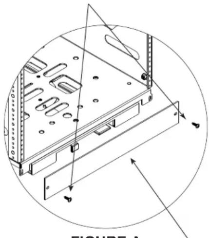
1) Remove two (2) #10-32 rack screws securing locking trim panel to SRSR base and set aside. (FIGURE A)
2) Extend the sliding carriage on the SRSR base.
RACK SCREWS #10-32 (2)
natural_image
Technical line drawing of a server rack with mounting holes and ventilation ducts, enclosed in a circular boundary (no text or symbols)FIGURE A
LOCKING
TRIM PANEL
ASSEMBLY (CONTINUED)

3) Install both cable management supports to SRSR base using one (1) 5/16-18 flange nut and two (2) #10-32 x 1/2" hex head screws per side. (FIGURE B)
4) Using provided #10-32 rack screws, install lacer bars as desired to cable management supports with flat side facing up and edges on outside of supports. (FIGURE C)
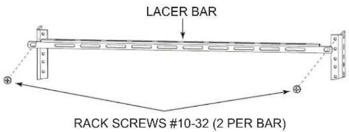
FIGURE C
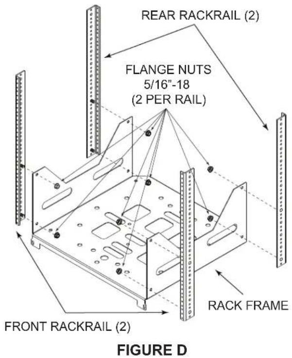
5) Observe rackrail labels for proper orientation and install front and rear rackrail pairs to rack frame using two (2) 5/16"-18 flange nuts per rail. (FIGURE D)
NOTE: Hand-tighten only.
ASSEMBLY (CONTINUED)
6) Install squaring panels one third of the way down from top of front and rear rackrail using four (4) #10-32 rack screws per panel. (FIGURE E)
NOTE: Load equipment before removing squaring panels.
7) SRSR'S WITH 25 SPACES OR MORE: Install front-to-rear braces to rackrails as shown using two (2) 5/16"-18 flange nuts per brace. (FIGURE F)

8) Fully tighten front and rear rackrails to rack frame.
9) Remove four (4) wing nuts beneath the sliding carriage to release the rack frame. (FIGURE G)
10) Lift the rack frame off sliding carriage using the provided handles. (FIGURE G)
11) Position and center the SRSR base in millwork to desired setback. Please refer to Middle Atlantic Products A & E spec sheet # 96-985 for complete millwork dimensions. Maximum suggested functional setback is 2" (more setback reduces usable depth).


FIGURE G
ASSEMBLY (CONTINUED)
12) Extend sliding carriage forward to reveal rear preliminary mounting hole in SRSR base.
(FIGURE H)
13) Insert fastener (not supplied) through rear preliminary mounting hole to secure rear of SRSR base to millwork. (FIGURE H)
14) Extend sliding carriage further forward to reveal front preliminary mounting hole in SRSR base. (FIGURE H)
15) Insert fastener (not supplied) through front preliminary mounting hole to secure front of SRSR base to millwork. (FIGURE H)
16) Verify setback clearances and complete attachment of SRSR base to millwork using mounting points shown on (FIGURE J) on page 7.
17) Verify setback clearances and complete attachment of SRSR base to millwork using mounting points shown on (FIGURE J) on page 7.

CAUTION! Failure to install all required hardware may result in damage to the equipment and possible injury to the user.
18) Place rack frame on sliding carriage using provided handles. (FIGURE G)
NOTE: Mounting studs on underside of rack frame must be inserted into mounting holes in sliding carriage.
19) Re-install the rack frame to the sliding carriage using four (4) wing nuts.
(FIGURE G)
20) Depress the lockout lever on the front of the sliding carriage and push the rack frame into the millwork. (FIGURE I)
21) Retract the sliding carriage on the SRSR base. (FIGURE G)
22) Replace two (2) #10-32 rack screws (from step #1) to secure locking trim panel to SRSR base. (FIGURE G)
REAR PRELIMINARY MOUNTING HOLE

FIGURE H

FIGURE I
SRSR MOUNTING POINT LOCATIONS
SRSR-2, SRSR-4
![18.125 [460] 12.125 [308] * Preliminary Mounting Holes 17.34 [440] 15.78 [401] 13.97 [355] .281 dia. [7] 11.0 [279] 8.0 [203] 19.23 [488] 2.78 [71] 1.59 [40] 0.00 [0] (from trim) * 3.78 [96] 9.59 [244] 19.19 [487] FRONT (12 Additional mounting holes as shown) FIGURE 1](/content/2026/05/946726/images/65375965e8d6e9929ccbe49c6d195c4d4f8e7bb2ecaeadd3ef7ca738bccc4ded.jpg)
FIGURE J
![SRSR-X 18.125 [460] 12.125 [308] 22.34 [567] 18.97 [482] .281 dia. [7] 15.78 [401] 2.78 [71] 1.59 [40] 0.00 [0] (from trim) 9.59 [244] 19.19 [487] 11.0 [279] 8.0 [203] 3.78 [96] 23.23 [590] * Preliminary Mounting Holes FRONT (12 Additional mounting holes as shown) All dimensions in inches [dimensions in brackets are millimeters]](/content/2026/05/946726/images/8e866471fb0f95e76b049ad9dd71a0e33a513c0c224828318dccabf58685e15a.jpg)
SRSR ROTATING SLIDING RAIL SYSTEM
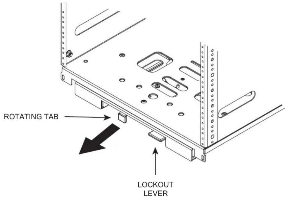
To rotate the sliding carriage, pull rotating tab as shown below. (FIGURE K) The sliding carriage conveniently locks in the 60° and 90° positions for servicing. The the 0° position locks for closure.

CABLE MANAGEMENT TIPS
- Route cables in the direction of the rack rotation as shown. (FIGURE L)
- Select one side of rack for signal cables, and the opposite side for power cables.
- Lace cables as shown, ensuring cables are fairly taut. This ensures that the service loop will be the correct length and not be pinched when closing the rack.

ROTATE RACK IN THE DIRECTION OF CABLE ROUTING.
INSTALLING OPTIONAL GASKET MODEL # BG17

IMPORTANT NOTE: WHEN USING THE GASKET, THE MINIMUM MILLWORK ROUGH OPENING WIDTH IS 19-5/8"
1) Remove dust and debris from rack surface with included wipes.
2) While removing paper backing, gently pull self-adhesive gasket from bottom to top of rack.
3) Align and adhere gasket at top of rackrail and continue across top (if applicable). Repeat for opposite rackrail.
NOTE: Press firmly along length of gasket.
4) Trim excess length.
HINT: If gasket is needed across the top of the rack, the top space will require a flanged panel or a component with a flat top.

WARRANTY
Middle Atlantic Products (the "Company") warrants the SRSR SERIES ROTATING SLIDING RAIL SYSTEM to be free from defects in material or workmanship under normal use and conditions for a period of (3) three years from date of shipment by the Company.
The Company's entire liability to the purchaser, and the purchaser's (or any other party's) sole and exclusive remedy, under this warranty shall be limited, at the Company's option, to either (a) return of and refund of the price paid for, or (b) repair or replacement at the Company's factory of the products purchased, or any part or parts thereof, which the Company has determined to be defective after inspection thereof at the Company's factory.
This warranty does not cover damage due to acts of God, accident, misuse, abuse or negligence by parties other than the Company, or any modification or alteration of the products. In addition, this warranty does not cover damage due to improper handling, assembly, installation or maintenance.
THIS WARRANTY IS IN LIEU OF ALL OTHER WARRANTIES OF ANY KIND, EITHER EXPRESSED OR IMPLIED, INCLUDING, BUT NOT LIMITED TO, IMPLIED WARRANTIES OF MERCHANTABILITY AND FITNESS FOR A PARTICULAR PURPOSE.
TO THE MAXIMUM EXTENT PERMITTED BY APPLICABLE LAW, IN NO EVENT SHALL THE COMPANY BE LIABLE FOR ANY SPECIAL, INCIDENTAL, INDIRECT, OR CONSEQUENTIAL DAMAGES WHATSOEVER (INCLUDING, WITHOUT LIMITATION, DAMAGES FOR LOSS OF BUSINESS PROFITS, BUSINESS INTERRUPTION OR ANY OTHER PECUNIARY LOSS) ARISING OUT OF THE USE OF THE PRODUCTS PURCHASED, EVEN IF THE COMPANY HAS BEEN ADVISED OF THE POSSIBILITY OF SUCH DAMAGES. THE COMPANY'S LIABILITY TO THE PURCHASER (OR ANY OTHER PARTY) HEREUNDER, IF ANY, SHALL IN NO EVENT EXCEED THE PURCHASE PRICE OF THE PRODUCTS PAID TO THE COMPANY.
Corporate Headquarters
Corporate Voice 973-839-1011 - Fax 973-839-1976
International Voice +1 973-839-8821 - Fax +1 973-839-4982
middleatlantic.com - info@middleatlantic.com
Middle Atlantic Canada
Voice 613-836-2501 - Fax 613-836-2690
middleatlantic.ca - customerservicecanada@middleatlantic.ca
Factory Distribution
USA: NJ - CA - IL Canada: ON - BC
At Middle Atlantic Products we are always listening. Your comments are welcome.
Middle Atlantic Products is an ISO 9001 and ISO 14001 Registered Company.

Middle Atlantic Products
what great systems are built on™
middleatlantic.com ■ 800.266.7225

- THANK YOU
- PRODUCT FEATURES
- IMPORTANT SAFETY INSTRUCTIONS
- IMPORTANT WARNINGS AND CAUTIONS!
- HARDWARE KIT INCLUDES
- QTY DESCRIPTION
- TOOLS REQUIRED
- Phillips Head Screwdriver
- ASSEMBLY
- ASSEMBLY (CONTINUED)
- SRSR MOUNTING POINT LOCATIONS
- SRSR ROTATING SLIDING RAIL SYSTEM
- CABLE MANAGEMENT TIPS
- INSTALLING OPTIONAL GASKET MODEL # BG17
- WARRANTY
- Corporate Headquarters
- Middle Atlantic Canada
- Factory Distribution
- Middle Atlantic Products
Brand : Middle Atlantic
Model : SRSR-4-12
Category : Mounting bracket