
PTHC38PK - Heating Napoleon - Free user manual and instructions
Find the device manual for free PTHC38PK Napoleon in PDF.


User questions about PTHC38PK Napoleon
0 question about this device. Answer the ones you know or ask your own.
Ask a new question about this device
Download the instructions for your Heating in PDF format for free! Find your manual PTHC38PK - Napoleon and take your electronic device back in hand. On this page are published all the documents necessary for the use of your device. PTHC38PK by Napoleon.
USER MANUAL PTHC38PK Napoleon
FIREPLACES & GRILLS
PROPANE PATIO HEATER

WARNING: For Outdoor Use Only.
FOR YOUR SAFETY
If you smell gas:
- Shut off gas to the appliance.
- Extinguish any open flame.
- if odor continues, immediately call gas supplier.
FOR YOUR SAFETY
Do not store or use gasoline or other flammable vapors or liquids in the vicinity of this or any other appliance.
CAUTION: Retain these instructions for future use.


Model No.:SRPH01
Master Contract No.:217109
Customer Item No.: PTHC38PK
Manual, Instructions & Parts List
TOOLS AND PARTS NEEDED FOR ASSEMBLY

DANGER

CARBON MONOXIDE HAZARD
This appliance can produce carbon monoxide which has no odor.
Using it in an enclosed space can kill you.
Never use this appliance in an enclosed space such as a camper, tent, car or home.
WARNING: Improper installation, adjustment, alteration, services or maintenance can cause injury, death or property damage.
Read the installation, operating and maintenance instructions thoroughly before installing or servicing this equipment.
WARNING
For outdoor use only.
Cylinders to be used must be constructed and marked in accordance with US DOT specifications.
Storage indoors is permissible only if the cylinder is removed.
The unit should be secured or moved indoors if winds exceed 35 km/h.
Note: 20 Pound, 5 Gallon LPG Tank is not supplied.
TOOLS NEEDED:
7/16" Wrench
3/8" Open End Wrench
Adjustable Wrench
Philips Head Screwdriver
Leak Detection Solution (Instructions page 9)
The bill of sale or copy will be required together with the serial and model numbers when making any warranty claims from NAC. Do not return parts to our address without first obtaining a return authorization number. The customer service department is available between 9AM and 5PM (EST).
NAC Customer Care
214 Bayview Drive
Barrie, ON
Canada, L4N 4Y8
1-866-820-8686
1-705-727-4282 (fax)
care@nac.on.ca
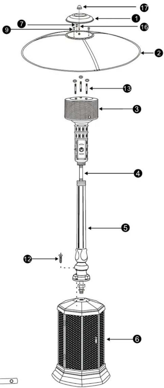
PARTS
① 1 Center Decoration Cap
② 3 Reflector
③ 1 Head Assembly
4 1 Gas Hose
5 1 Post
6 1 Gas Cylinder Housing
7 3 M6 Nuts
8 4 M8 Nuts
9 6 6mm Washers
10 4 M8 Lock Washers
11 6 M3 X 6 Bolts
12 4 M8 X 35mm Bolts
13 3 M6 X 70mm Double Pointed Bolts
14 1 Regulator
15 1 Cylinder (Not Supplied)
16 1 M6 x 38 double pointed bolts
17 1 Top Decoration Cap
18 3 Reflector connetor


NOTE: PLEASE READ THE FOLLOWING SAFETY RULES
WARNING
This appliance must only be used outdoors. Using this product in an enclosed area may cause injury, death or property damage.
Read the instructions before use. This appliance must be installed in accordance with such regulations as are in force.
Do not use the heater in an explosive atmosphere. Keep the heater away from areas where gasoline or other flammable liquids or vapors are stored.
Prior to use, check for damaged parts such as hoses, regulators, pilot or burner.
Disconnect LPG bottle before moving the heater.
Do not attempt to alter unit in any manner. EXAMPLE: using the heater without the top canopy reflector or radiant screen. Do not shorten the burner post assembly.
The appliance shall not be used in basements or below ground level. It must always be placed on a solid and level surface.
Always assure there is ample fresh air ventilation. For outdoor use ONLY.
Never replace or substitute the regulator with any regulator other than the factory suggested replacement.
Do not clean the heater with cleaners that are combustible or corrosive.
Do not paint radiant screen, control panel or top canopy reflector.
All leak tests should be done with a soapy solution. NEVER USE AN OPEN FLAME TO CHECK FOR LEAKS.
The LP gas cylinder should be turned off when the heater is not in use.
At least once a year, the unit should be inspected for the presence of spiders, spider webs or other insects. Check the heater immediately if any of the following exist:
- The smell of gas in conjunction with extreme yellow colored tips of the burner flames.
- The heater does not reach temperature.
- The burner makes popping noise during use (a slight popping noise is normal when the burner is extinguished after using).
The propane hose with regulator assembly shall be located out of pathways where people may trip over it or in areas where the hose will not be subject to accidental damage.
Children and adults should be aware of the hazards of high surface temperature.
Young children should be carefully supervised when they are in the area of the heater.
Clothing or other flammable material should not be hung from the heater, or placed on or near the heater.
Any guard or other protective device removed for servicing the heater must be replaced prior to operating the heater.
Installation and repair should be done by a qualified service person. The heater should be inspected before use and cleaning may be required at least once a year, or as necessary. It is imperative that control compartment, burner and circulating air passageways of the heater be kept clean.
Keep the appliance area clear of combustible materials such as gasoline and other flammable vapors and liquids.
Do not obstruct the flow of combustion and ventilation air.
Keep the ventilation opening of the cylinder enclosure free and clear of debris.
IGNITER BATTERY INSTALLATION
Instruction For Installing Battery
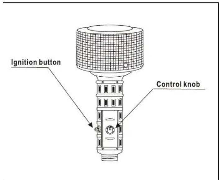
Remove igniter button by turning counter clockwise. Install "AAA" battery with positive terminal up as indicated in diagram. Replace igniter button.
Replace Battery

NOTE: Assembly of this heater requires basic mechanical skills. Proper assembly is the responsibility of the installer.
Step 1 ----Attach Post to Gas Cylinder Housing
Place the post on the top of the gas cylinder housing. Fasten the post to the gas cylinder housing using the four (4 pcs) M8 X35mm Bolts, 8mm Lock Washer, Nuts for M8 X35mm Bolts.
Step 2 ----Attach Head Assembly to Post
Slide the gas hose with the attached Head assembly through the top of the post and down through the hole in the top of the gas cylinder housing. Screw the head assembly on to the post, and tighten securely.


NOTE: Assembly of this heater requires basic mechanical skills. Proper assembly is the responsibility of the installer.
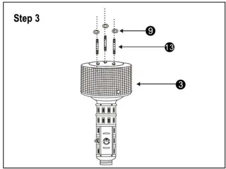
Step 3 ----Attach Double Threaded Bolt to Head Assembly
Attach double threaded bolts (3 pcs) and 6mm washers (3 pcs) to the top of head assembly and tighten the bolts securely.
Step 4 ---- Assemble Reflector Cap
Unwrap the 3pcs reflector segment up as illustrated; Insert the connector into the reflector and fix it with 2pcs M3 x 6 bolts; Use the same way for other conjoined parts.

NOTE: Assembly of this heater requires basic mechanical skills. Proper assembly is the responsibility of the installer.
Step 5 ---- Attach Reflector Cap and Decoration Cap to the top of Head Assembly
Load reflector to the top of head assembly by M6X70 double pointed bolts 13 (3pcs), 6MM washers 9 (3pcs) and nut 7 (3pcs) Attach center decoration cap and top decoration capto reflector by M6X38 Bolt 16 (1pcs)
Step 6 ---- Connect Gas Line to Cylinder
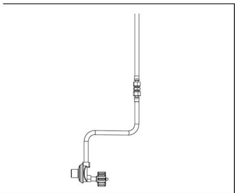
Attach Gas hose to regulator hose with 3/8 Inch Open End Wrench and Adjustable Wrench. Attach regulator to cylinder. Tighten securely. Move cylinder to the plate of base assembly.

Step 6

NOTE: Always check the following connections.
Check all connections on the hose regulator assembly.
Check the regulator to the LP gas cylinder connection. Note that the regulator adapter is a reverse thread.
Check the hose to the intake pipe to make certain that it is not kinked or in a position that could cause it to kink. Hand tighten and then take a 1/2 turn with an adjustable wrench.
The remaining connections are to be tested after this heater has been lit. (SEE LIGHTING INSTRUCTIONS PAGE10)
Check for leaks
Your Patio Heater has been checked at all factory connections for leaks. To check the connection at the gas hose/regulator/cylinder:
1) Make leak solution by mixing 1 part liquid dishsoap and 3 parts water.
2) Brush solution (or use spray bottle) onto the gas hose/regulator and regulator/cylinder connection.
3) Turn on gas. Inspect the connections and look for bubbles.
4) If no bubbles appear, the connection is safe.
5) If bubbles appear, there is a leak. Turn off the gas, loosen and re-tighten this connection.
6) If leak continues call a qualified service person.

OPERATION
WARNING: DO NOT attempt to operate heater until you have read and understand all precautions. Failure to do so can result in serious personal injury, death or property damage.
Before Turning Gas Supply ON
Your heater was designed and approved for OUTDOOR USE ONLY. DO NOT use it inside a building, or any other enclosed area. Make sure surrounding areas are free of combustible materials, gasoline and other flammable vapors or liquids. Ensure that there is no obstruction to air ventilation. Be sure all gas connections are tight and there are no leaks. Be sure the access panel is clear of debris. Be sure any component removed during assembly or servicing is replaced and fastened prior to starting.
Before Lighting
Heater should be thoroughly inspected before each use, and by a qualified service person at least annually. If relighting, always wait at least 5 minutes.
This heater is tested for quality assurance. Ignition attempts should succeed 8 out of 10 attempts.
LIGHTING INSTRUCTIONS
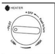
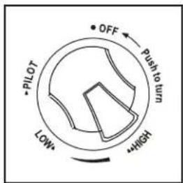
- Push and turn the control knob clockwise to the off position.
- Fully open the propane tank valve or natural gas supply valve.
- Push and turn the control knob counter-clockwise to the pilot position. Depress the control knob. Push and hold the igniter button until the pilot lights.
- Once the pilot lights, release the igniter button and continue to depress the control knob for 30 seconds.
- After depressing the control knob for 30 seconds, release the control knob and turn it counter-clockwise to the low or high position.
Note: If the pilot light will not ignite, turn the control knob to the off position, and fully close the propane tank valve or natural gas supply valve. Wait 5 minutes and then repeat steps 2-4. Alternately, the pilot can be lit using a wand lighter. Push and turn the control knob to the pilot position. Depress the control knob. Insert the lit lighter through the ignition hole on the emitter screen. Once the pilot lights, remove the lighter and continue to depress the control knob for 30 seconds.
Whenever the unit is disconnected from the natural gas supply, the supply lines fill with air. Expect a delay in lighting the pilot, the first time the unit is lit after reconnecting.
INSTRUCTIONS D'ALLUMAGE
If at any time you are unable to light burner and smell gas, wait 5 minutes to allow gas to dissipate before attempting to light heater.
If after 1 minute you are unable to light burner, wait 5 minutes and allow flammable vapors to dissipate before attempting to light heater again.
WARNING
FOR YOUR SAFETY:
DO NOT touch or move heater for at least 45 minutes after use.
Allow emitter and dome to cool before touching.



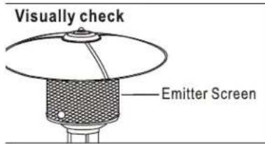
Note: The flame pattern at the emitter grid should be visually checked whenever the heater is operated. Normally the burner flame is blue, but little yellow flame is acceptable. If flames extend beyond the surface of the emitter grid, flame is lifting off the or there is a black soot (carbon) accumulating on the emitter grid or reflector, the heater should be turned off immediately. The heater should not be operated again until services and or replaced.
If you experience any ignition problem, turn off the heater and gas supply, and consult "Troubleshooting" on page 14.
When lit for the first time the heater may emit a slight odor and smoke. This is a normal temporary condition caused by the "burn in" of paints and lubricants used in the manufacturing process and will not occur again. Simply run the heater on "high" for 30 minutes.
The burner may be noisy when initially turned on. To eliminate excessive noise from the burner, turn the Control Knob to the "LOW" position. Then turn the knob to the level of heat desired.
When heater is ON:
Emitter screen will become bright red due to intense heat. The color is more visible at night. Burner will display tongues of blue flame. These flames should not be yellow or produce thick black smoke, indicating an obstruction of airflow through the burners.
Operation Pressure Checked
If the flame is very small, this is because the supply pressure is not enough.
1) Turn the control knob to "OFF" position.
2) Wait five (5) minutes before attempting to relight pilot.
3) Repeat steps beginning with step 3 on page 10.
Never leave the heater unattended while in use. Follow the Shut Down Instructions outlined below.
SHUT DOWN INSTRUCTIONS
1) Push in and turn control knob clockwise to "OFF" position.
2) Turn off the natural gas supply valve.
Note: After use, some discoloration of the emitter screen is normal.
FERMETURE
Note: After use, some discoloration of the emitter screen is normal.
The Event of Gas Leakage
1) Turn the control knob to "OFF" position.
2) Wait 5 minutes to allow gas to dissipate.
3) If odor continues, immediately call gas supplier.
Handle with extreme care.


BE CAREFUL: WHEN CERTAIN MATERIALS OR ITEMS ARE STORED UNDER THIS SPACE HEATER WHILE IN USE, THEY WILL BE SUBJECT TO RADIANT HEAT AND COULD BE SERIOUSLY DAMAGED.
This heater is primarily used for the heating of outdoor patios, decks, pool and spa areas.
Always make sure that adequate fresh air ventilation is provided. Follow the spacing tolerances shown in Figure 1.
The minimum clearances shown in Figure1 must be maintained at all times.
The installation must conform to local codes, or in the absence of local codes, with the standard for the storage and handling of liquid petroleum gases, ANSI/NFPA 58-1986, or most recent addition. For Canada, with the current CAN1-B149.
This heater must be placed on firm level ground.
Never operate in an explosive atmosphere. Keep away from areas where gasoline or other flammable liquids or vapors are stored or used.

Figure 1
MAINTAINANCE/STORAGE
MAINTENANCE :
To enjoy years of outstanding performance from your heater make sure you perform the following maintenance activities on a regular basis:
- Keep exterior surfaces clean.
- Use warm soapy water for cleaning. Never use flammable or corrosive cleaning agents.
- While washing your unit, be sure to keep the area around the burner and pilot assembly dry at all times. If the gas control is exposed to water in any way, DO NOT try to use it. It must be replaced.
- Air flow must be unobstructed. Keep controls, burner and circulating air passageways clean. Signs of possible blockage include:
• Gas odor with extreme yellow tipping of flame.
• Heater does NOT reach the desired temperature.
• Heater glow is excessively uneven.
• Heater makes popping noises. - Spiders and insects can nest in burner or orifices. This dangerous condition can damage heater and render it unsafe for use. Clean burner holes by using a heavy-duty pipe cleaner. Compressed air may help clear away smaller particles.
- Carbon deposits may create a fire hazard. Clean dome and emitter with warm soapy water if any carbon deposits develop.
CLEANING :
- Remove the reflector and emitter by removing the 4 screws that fasten the emitter to the lower screen cone. Any debris in the burner port should be cleared. Any rust can be removed carefully with a wire brush. Never use a piece of wood, or other materials that might break off and block the ports.
- Remove lower cone cylinder by removing the 4 screws which attach the lower cone cylinder to the control cylinder. Clear debris on the surface of thermocouple.
- Remove the 4 screws at the bottom of control cylinder. Clear the debris of the surface and the inside of the injection nozzle.
NOTE :
It is recommended that the painted components from the emitter down are periodically protected with a coat of automobile wax. If repainting is necessary, paint only the post and gas cylinder housing. Never paint the reflector, head assembly, or instruction plate on post.
Keep exterior surfaces clean:
Use warm soapy water for cleaning. Never use flammable or corrosive cleaning agents. While washing your unit, be sure to keep the area around the combustion assembly dry at all times. If the gas control is exposed to water in any way, DO NOT try to use it. It must be replaced.

WARNING FOR YOUR SAFETY :
DO NOT touch or move heater for at least 45 minutes after use. Allow all burner elements to cool before touching.
NOTE: In a salt-air environment, such as near an ocean, corrosion occurs more quickly than normal. Frequently check for corroded areas and repair them promptly.
NOTE: Wait until heater is cool before covering.
STORAGE :
Between uses:
- Turn the control knob to "OFF" position.
- Turn LP cylinder to "OFF" position.
- Store heater upright in an area sheltered from direct contact with inclement weather (such as rain, sleet, hail, snow, dust and debris).
- If desired, cover heater to protect exterior surfaces and to help prevent debris in air passages.
During periods of extended inactivity or when transporting:
- Turn the control knob to "OFF" position.
- Disconnect LP Cylinder and move to a secure, well-ventilated location outdoors. Do NOT store in a location that will exceed 125 degrees F.
- The propane cylinder must be stored outdoors in well-ventilated area, and it must be out of reach of children, and not in a building, garage or any other enclosed area.
- Store heater upright in an area sheltered from direct contact with inclement weather (such as rain, sleet, hail, snow, dust and debris). If desired, cover heater to protect exterior surfaces and to help prevent debris in air passages.
TROUBLESHOOTING
| PROBLEM | PROBABLE CAUSE | SOLUTION |
| Pilot will not light | Gas valve may be OFF | Turn the gas valve ON |
| Fuel Tank empty | Refill LP gas tank | |
| Orifice blocked | Clean or replace orifice | |
| Air in supply system | Purge air from lines, with knob in pilot position, depress and hold in, to release air. | |
| Loose connection | Check all fittings | |
| Dead battery | Replace battery | |
| Pilot will not stay on | Debris around pilot | Clean dirty area |
| Loose connection | Tighten connection | |
| Thermocouple bad | Replace thermocouple | |
| Gas leak in line | Check connections | |
| Lack of fuel pressure | Fuel tank is near empty | |
| Burner will not light | Pressure is low | Supply pressure is not enough |
| Orifice blocked | Remove, clean and replace | |
| Control valve not ON | Turn valve to ON | |
| Thermocouple is bad | Replace thermocouple | |
| Pilot light assembly bent or not in correct location | Place pilot in proper position and retry |
LIMITED PRODUCT WARRANTY
This product has a six month limited warranty, which covers workmanship and material quality. NAC warrants to the original purchaser only, that when this product is subject to normal residential use, it is free from defects in workmanship and materials for a period of six months from the original date of purchase. This warranty does not cover damage caused by use in commercial or rental applications, misuse, lack of maintenance, hostile environments, improper fuel/gas supply, wind/weather damage, damage or repairs related to spider or insect nesting, accidents or alterations. This warranty is non-transferable and may not be extended what so ever by any of our representatives. The limited warranty further does not cover any scratches, dents, corrosion or discoloring due to heat or damage from abrasive or chemical cleaners. NAC is not liable for any transportation costs, labor costs, or export duties relating to the delivery or installation of replacement parts.
NAC reserves the right to have its representative inspect any product or part prior to honouring any warranty claim. Warranty is limited to providing a replacement part or a repair part, at our option, during the warranty period. Any work or repair of this product must be performed by qualified service personnel. The warranty period is not extended by the repair or replacement. NAC is not responsible for the installation, labor or any other expenses associated with the re-installation of a warranted part.
The bill of sale or copy will be required together with the serial and model numbers when making any warranty claims. Do not return parts to our address without first obtaining a return authorization number. The customer service department is available between 9AM and 5pm (EST).
NAC Customer Care
214 Bayview Drive
Barrie, ON
Canada, L4N 4Y8
1-866-820-8686
1-705-727-4282 (fax)
wecare@napoleonproducts.com
This warranty may give you specific legal rights that vary by state or province.
- PROPANE PATIO HEATER
- FOR YOUR SAFETY
- TOOLS AND PARTS NEEDED FOR ASSEMBLY
- DANGER
- CARBON MONOXIDE HAZARD
- WARNING
- TOOLS NEEDED
- PARTS
- NOTE: PLEASE READ THE FOLLOWING SAFETY RULES
- IGNITER BATTERY INSTALLATION
- INSTRUCTION FOR INSTALLING BATTERY
- STEP 1 ----ATTACH POST TO GAS CYLINDER HOUSING
- STEP 2 ----ATTACH HEAD ASSEMBLY TO POST
- STEP 3 ----ATTACH DOUBLE THREADED BOLT TO HEAD ASSEMBLY
- STEP 4 ---- ASSEMBLE REFLECTOR CAP
- NOTE: ALWAYS CHECK THE FOLLOWING CONNECTIONS
- CHECK FOR LEAKS
- OPERATION
- WARNING: DO NOT ATTEMPT TO OPERATE HEATER UNTIL YOU HAVE READ AND UNDERSTAND ALL PRECAUTIONS. FAILURE TO DO SO CAN RESULT IN SERIOUS PERSONAL INJURY, DEATH OR PROPERTY DAMAGE
- BEFORE TURNING GAS SUPPLY ON
- BEFORE LIGHTING
- LIGHTING INSTRUCTIONS
- INSTRUCTIONS D'ALLUMAGE
- WHEN HEATER IS ON
- OPERATION PRESSURE CHECKED
- SHUT DOWN INSTRUCTIONS
- FERMETURE
- THE EVENT OF GAS LEAKAGE
- MAINTAINANCE/STORAGE
- MAINTENANCE
- CLEANING
- NOTE
- KEEP EXTERIOR SURFACES CLEAN
- WARNING FOR YOUR SAFETY
- STORAGE
- BETWEEN USES
- DURING PERIODS OF EXTENDED INACTIVITY OR WHEN TRANSPORTING
- LIMITED PRODUCT WARRANTY
Brand : Napoleon
Model : PTHC38PK
Category : Heating