
F5BM - Outboard motor COLEMAN - Free user manual and instructions
Find the device manual for free F5BM COLEMAN in PDF.


| Product Type | Outboard Motor |
| Brand | Coleman |
| Model | F5BM |
| Engine Type | 4-Stroke |
| Displacement | 112 cm³ |
| Maximum Output | 3.6 kW (5 HP) at 5000 rpm |
| Full Throttle Operating Range | 4000 – 5000 rpm |
| Idling Speed (in Neutral) | 1500 ± 50 rpm |
| Fuel Type | Regular Unleaded Gasoline |
| Built-in Fuel Tank Capacity | 1.3 L |
| Engine Oil Capacity | 0.5 L |
| Recommended Engine Oil | SAE 10W-30 or 10W-40 |
| Gear Oil Capacity | 100 cm³ |
| Recommended Gear Oil | Hypoid Gear Oil SAE #90 |
| Spark Plug | BR6HS (gap 0.6–0.7 mm) |
| Starting System | Manual Recoil Starter |
| Gear Ratio | 2.08 (27/13) |
| Weight (Short Shaft) | 24.5 kg |
| Weight (Long Shaft) | 25.5 kg |
| Overall Height (Short Shaft) | 1029 mm |
| Overall Height (Long Shaft) | 1156 mm |
| Overall Length | 717 mm |
| Overall Width | 361 mm |
| Propeller | Standard propeller included (pitch may vary) |
| Warranty | 1 year limited warranty, 5 years/175 hours emissions warranty |
Frequently Asked Questions - F5BM COLEMAN
User questions about F5BM COLEMAN
0 question about this device. Answer the ones you know or ask your own.
Ask a new question about this device
Download the instructions for your Outboard motor in PDF format for free! Find your manual F5BM - COLEMAN and take your electronic device back in hand. On this page are published all the documents necessary for the use of your device. F5BM by COLEMAN.
USER MANUAL F5BM COLEMAN
natural_image
Two people riding an inflatable boat on water, with a Coleman 2 electric scooter nearby (no visible text or symbols)Owner's Manual
Model: F5BM
Operation, Maintenance and Warranty
Always read and understand the Owner's Manual before operating the outboard motor for the first time.
YOUR COLEMAN OUTBOARD MOTOR
- “COLEMAN” outboard motors are powerful, economic and safe, manufactured with advanced technology. Please read this manual carefully before operating your outboard motor. A thorough understanding of this manual will give instructions for proper operation, maintenance and care.
- “COLEMAN” seeks continuous improvement in product quality. Therefore, while this manual contains the most current product information available at the time of printing, there may be minor discrepancies between your machine and this manual. If there is any question concerning the manual, please contact COLEMAN Outboard Motors 888-405-8725
- Data, illustrations or explanations in this Owner's Manual do not constitute base for any legal claim against COLEMAN Outboard Motors.
COLEMAN OUTBOARD MOTORS
Engine Identification Numbers
Outboard motor serial number:
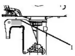
The outboard motor serial number is marked on the label. The label can be found on the mounting bracket left assembly or on the upper part of the bracket swivel. Record your outboard motor serial number in the spaces provided to assist you in ordering spare parts from COLEMAN Outboard Motors, or for reference in case your outboard motor is stolen.
natural_image
Technical line drawing of a mechanical assembly with no visible text or symbols
- Outboard motor serial number location
Serial number as follows:
SN


Engine serial number
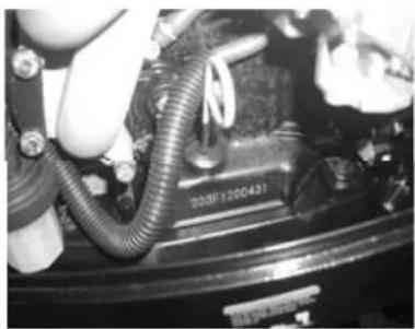
The engine serial number is engraved on the aluminum casting of engine.
natural_image
Close-up of a car engine bay with hoses and a hand adjusting components (no visible text or symbols)Serial number:

Manufacturer's Declaration
This outboard motor complies with the requirements of Directive 2003/44/EC in relation to the exhaust and noise emissions. The following installation and maintenance instructions, if applied, guarantee that the outboard motor will remain in compliance with:
-
Exhaust emissions limits throughout the normal life or the engine (350 hours or 10 years, whichever occurs first) and under normal conditions of use.
-
Noise emissions limits under normal conditions of use.
COLEMAN LIMITED WARRANTY
This Warranty is NOT the Emissions Control Warranty Please note this is a general Limited Warranty for this product. It IS NOT an Emissions Control Warranty. Please see the Emissions Control Warranty in this manual for warranties covering Emission components.
The Warranty
Coleman Outboard Motors offers the following warranty to the initial purchaser of this new Coleman Outboard. The initial purchaser is defined as the first person to purchase a new Coleman Outboard Motor from an Authorized Retailer of Coleman Outboard Motors.
The limited warranty period for this product is 1 year from the date of purchase shown on the original sales receipt.
What is a Defect?
The Outboard Motor is warranted to be free from manufacturing defects in material and workmanship for a period of 1 year from the date of purchase shown on the sales receipt. During this period of time Coleman Outboards will, at its option, either repair or replace any original Coleman Outboard part which is covered by this warranty and is proven to be defective in workmanship or material.
To qualify for this warranty the part:
- Must have been purchase from Coleman Outboards or from an authorized Coleman Outboards Retailer.
- This warranty does not apply to any outboard motor which is used in competition or used in a manner not consistent with the normal and proper intended use for the outboard Motor. This Outboard Motor is not intended for rental or commercial use.
Who Can Perform Repairs Under this Warranty?
Repairs under this warranty should be performed by an authorized Coleman Outboard Retailer or comparable servicing dealer.
How to get service under this warranty
To get warranty service call Coleman Outboard Motors 888-405-8725 for the location of your local servicing retailer / dealer. Please do not return the product to the retailer where the product was purchased unless instructed to do so by Coleman Outboard Motors.
The retailer of this product does not make any warranty of its own and has no authority to implement this warranty on behalf of Coleman Outboard Motors without the approval of Coleman Outboard Motors. A COPY OF YOUR SALES RECEIPT IS REQUIRED FOR WARRANTY SERVICE.
What this Warranty Does Not Cover
This warranty does not cover the following
- Damage due to lack or improper maintenance as described in this manual.
- Damage which is caused by normal use and not caused by a defect in materials or workmanship.
- Use of the product which is not consistent with the intended use as described in the operating instructions.
- Any expendable maintenance item which need replacement or service as part of normal maintenance, unless such items have defects in material or workmanship which cause failure or premature wear.
- Any product which has been altered or modified in a manner not consistent with the original design of the product or in a manner not approved by Coleman Outboard Motors.
- Prop
- Damage or failures due to abuse, neglect, or misuse of the product.
Limitations of this Warranty
This warranty does not cover and Coleman Outboard Motors disclaims any responsibility for:
- Loss of time or loss of use of the product.
- Transportation costs to and from the authorized center.
COLEMAN/PARSUN - EMISSIONS CONTROL SYSTEM WARRANTY STATEMENT YOUR WARRANTY RIGHTS AND OBLIGATIONS
The emission control system warranty period for this outboard motor begins on the date the motor is delivered to the first purchaser other than an authorized dealer, or the date it is first used as a demonstrator, lease, or company outboard motor, whichever comes first and continues for 5 years after that date, or 175 hours, whichever comes first, provided there has been no abuse, neglect or improper maintenance of your motor. Where a condition exists, Coleman Outboards will repair your motor at no cost to you, including diagnosis, parts and labor. If an emission-related part on our motor is defective, the part will be repaired or replaced by Coleman Outboard Motors. This is your emission control defects warranty.
OWNER'S WARRANTY RESPONSIBILITIES
As the outboard motor owner, you are responsible for the performance of the required maintenance. You should maintain a record of all maintenance performed on your motor and retain all receipts covering maintenance on your motor. You may not be denied a warranty claim solely because of your failure to ensure the performance of all scheduled maintenance or lack of maintenance records or receipts. You are responsible for presenting your vehicle to an authorized dealer/service center as soon as a problem exists. The warranty repairs should be completed in a reasonable amount of time, not to exceed 30 days.
As the outboard motor owner, you should be aware that you may be denied your warranty coverage if your outboard motor or a part has failed due to abuse, neglect, improper maintenance, or unapproved modifications.
Coverage of repairs under this warranty applies only when repairs are completed at an authorized dealer or repair facility. Coleman Outboards will not cover repairs performed outside of an authorized dealer or repair facility, except in an emergency situation. The use of replacement parts not equivalent to the original parts may impair the effectiveness of your motors emission control system. If such a replacement part is used and an authorized dealer or repair facility determines it is defective or causes a failure of a warranted part, your claim for repair to bring your vehicle into compliance with applicable standards may be denied.
If an emergency situation exists when a warranted part or a dealer/service center is not reasonably available to the owner, repairs may be performed at any available service establishment, or by the owner, using any replacement part. Coleman Outboards shall reimburse the owner of the expenses, including diagnostic charges, not to exceed Coleman Outboards suggested retail price for all warranted parts replaced and labor charges based on Coleman Outboards recommended time allowance for the warranty repair and the geographically appropriate hourly rate. The owner may reasonably be required to keep receipts and failed parts in order to receive compensation. The Emission Control System Warranty is in addition to the standard Limited Warranty
EXCLUSIONS AND LIMITATIONS
This warranty does not cover the following:
Failures or malfunctions of the emission control systems caused by abuse, alteration, accident, misuse, the use of lead gasoline. Replacement of expendable maintenance items unless they are original equipment defective in material or workmanship under normal use, and the first required replacement interval for the item has not been reached.
Expendable maintenance items include but are not limited to spark plugs, filters, lubricants, gaskets, hoses, and belts. Replacement of parts and other services and adjustments for required maintenance.
Any Motor equipped with an hour meter where the reading is altered so that actual use cannot be readily determined.
Repairs or replacements as a result of:
Accident
Misuse
Use of replacement parts or accessories not conforming to the original specifications which adversely affect performance.
Physical damage, corrosion, or defects caused by fire, explosions or similar caused beyond the control of Coleman Outboard Motors.
Failures not caused by a defect in material or workmanship.
WARRANTY COVERAGE
Coleman Outboards warrants that each new 2010 and later outboard motor is designed, built and equipped so as to conform at the time of initial retail purchase with all applicable regulations of the United States Environmental Protection Agency, and is free from defects in material and workmanship which cause such motor to fail to conform with the applicable regulations of the United States Environmental Protection Agency for the periods specified above.
Your emission control system warranty covers components whose failure would increase an engine's emission, including electronic controls, fuel injection system, carburetor, the ignition system, or any other system utilized in this outboard motor to control emissions if it is originally equipped. Also included may be hoses, connectors and other emission-related assemblies. Replacing or repairing other components including parts.
Use of the outboard motor in any type of racing or related events immediately and completely voids this and all other warranties.
LIMITED LIABILITY
The liability of Coleman Outboard Motors under the Emission Control System Warranty is limited solely to the remedying of defects in material and workmanship by an authorized dealer/service center at its place of business during customary business hours. This warranty does not cover inconvenience or loss of use of the vehicle or transportation of the motor to or from the authorized dealer. Coleman Outboard motors is not liable to any person for incidental, consequential or special damages of any description, whether arising out of express or implied warranty or any other contract, negligence or other tort or otherwise.
No express emission control system warranty is given by Coleman outboard Motors except as specifically set forth herein. Any emission control system warranty implied by law, including any warranty of merchantability or fitness for a particular purpose is limited to the express emission control system warranty terms stated in this warranty. The foregoing statements of warranty are exclusive and in lieu of all other remedies. All express warranties not stated in this warranty are disclaimed. Some states do not allow limitations on how long an implied warranty lasts, so the above limitations may not apply if it is inconsistent with the controlling state law.
No dealer is authorized to modify this Emission Control System Warranty. If you have any questions regarding your warranty rights and responsibilities, you should call Coleman Outboard Motors at 888-405-8725 (or you can write to 9820 E. Thompson Peak Pkwy., Scottsdale, AZ. 85255)
! WARNING
The engine exhaust from this product contains chemicals known to the state of California to cause cancer, birth defects or other reproductive harm.
California Proposition 65
To emphasize special important information in the manual, please note the following :

This is the alert symbol. The symbol means ATTENTION!, BECOME ALERT!, YOUR SAFETY IS INVOLVED.
To emphasize important safety information, the word WARNING, with the alert symbol, has special meaning.:

WARNING
Indicates a potential hazard that could result in SEVERE INJURY or DEATH to the operator, bystander or person inspecting or repairing the Outboard Motor.
To emphasize important information, the word CAUTION has special meaning.:
CAUTION:
Indicates special precautions that must be taken to avoid damage to the Outboard Motor
To emphasize important information, the word NOTE has special meaning.:
NOTE:
Indicates key information to make procedures easier or clearer to understand.
Coleman Outboard Motors is concerned about the environment and believes in conserving and protecting all natural resources. For this reason, owners should recycle, trade in, or dispose as appropriate, batteries and oil.
Table of contents
- Main components and General information....1
1.1.Main components....1
1.2. General information ....3
1.2.2 . Fueling instructions....4
1.2.3. Propeller selection....5
- Operation....6
2.1.Installation....6
2.1.1 Mounting height....7
2.1.2 Clamping the outboard motor....8
2.2 Breaking in engine....9
2.3 Pre-operation Checks 10
2.4 Filling fuel....11
2.5 Starting engine....1
2.6 Warming up engine....1
2.7 Shifting....18
2.7.1 Forward....18
2.7.2 Reverse....19
2.8. Tiller....20
2.9 Stopping engine....22
2.10 Trimming outboard motor....24
2.11.1 Tilting up....25
2.11.2 Tilting down....27
2.12 Cruising in other conditions....29
2.12.1 Cruising in shallow water ....29
2.12.2 Cruising in salt water....29
3. Maintenance .... 30
3.1. Greasing....30
3.2. Cleaning and adjusting spark plug....31
3.3. Checking fuel system....31
3.4. Inspecting idling speed....32
3.5. Changing engine oil....33
3.6. Checking wiring and connectors....34
3.7. Checking leakage....34
3.8. Checking propeller....35
3.8.1. Removing the propeller.... 36
3.8.2. Installing the propeller....36
3.9. Changing gear oil....37
3.10. Cleaning fuel tank....38
3.11. Checking and replacing anode(s).... 39
3.12. Checking top cowling....40
3.13. Maintenance table....40
- Transporting and storing outboard motor....43
4.1. Transporting....43
4.2. Storing....44 - Action in emergency....47
5.1. Impact damage....47
5.2. Starter will not operate....47
5.3. Treatment of submerged motor....50 - Troubleshooting....52
- Circuit diagram....56
1. Main components and General information 1.1 Main components

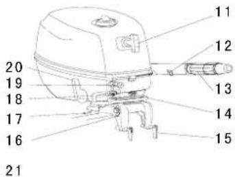

- Top cowling
- Top cowling lock handle
- Steering friction screw
- Anti-cavitation plate
- Propeller
- Cooling water inlet
-
Trim rod
-
Clamp bracket
-
Tiller handle
-
Engine stop button/
Engine stop lanyard switch
- Starter handle
- Throttle friction adjuster
-
Throttle grip
-
Carrying handle
- Clamp screw
- Rope attachment
- Tilt support bar
- Fuel joint
- Choke knob
-
Gear shift lever
-
Fuel tank*
Note:
* The fuel tank is equipped for the proper model.
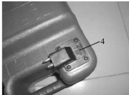
If your model includes a portable fuel tank, its parts are as follows:

-
Fuel tank cap
-
Fuel joint
natural_image
Close-up of a mechanical component with a labeled part (4), no visible text or symbols beyond the number-
Air vent screw
-
Fuel gauge
If your model includes a built-in fuel tank, its parts are as follows:

-
Air vent screw
-
Fuel tank cap
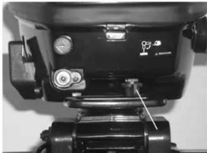
natural_image
Close-up of a black mechanical device with adjustment knobs and a lever mechanism (no visible text or symbols)-
Built-in fuel tank
-
Fuel cock (close position)

WARNING
- The fuel tank supplied with this engine could only be used as supply of fuel for its running and must not be as a fuel storage container.
- The fuel cock must be at close position while using portable fuel tank.
- Disconnect the fuel joint while using the built-in fuel tank.
1.2 General information
1.2.1 Specifications
Parameter
| Items | Data | Items | Data |
| Type of engine 4-stroke S Weight (L) 25.5Kg | |||
| Displacement | 112cm^3 Recommended fuel Unleaded regular gasoline | ||
| Bore X stroke 59mm×41mm | Built-in fuel tank capacity 1.3L | ||
| Gear ratio | 2.08 (27/13) | Recommended engine oil | SAE10W30 orSAE10W40 |
| Overall length | 717mm | Engine oil quantity | 0.5L |
| Overall width | 361mm | Recommended gear oil | Hypoid gear oil SAE # 90 |
| Overall height (S) | 1029mm | Gear oil quantity | 100cm^3 |
| Overall height (L) | 1156mm | Spark plug | BR6HS |
| Weight (S) | 24.5Kg | Spark plug gap | 0.6 ~ 0.7mm |
Performance
| Items | Data | Items | Data | |
| Maximum output | 2.9Kw/4500Rpm(4HP) | Valve clearance IN (cold engine) | 0.08 ~ 0.12mm | |
| 3.6Kw/5000Rpm(5HP) | Valve clearance EX (cold engine) | 0.08 ~ 0.12mm | ||
| Full throttle operating range | 4000 ~ 5000Rpm | Tightening torque for engine | Spark plug | 25.0Nm |
| Idling speed (in neutral) 1500±50Rpm | Engine oil drain bolt | 20.0Nm | ||
1.2.2 Fueling instructions
Fueling instructions:
Recommended gasoline: Regular unleaded gasoline, If it is not available, then premium gasoline.
If knocking or pinging occurs, use a different brand of gasoline or premium unleaded fuel. If leaded gasoline is usually used, engine valves and related parts should be inspected after every 100 hours of operation.

WARNING:
- Do not smoke when refueling, and keep away from sparks, flames, or other sources of ignition.
- Stop engine before refueling.
- Refuel in a well-ventilated area. Refuel portable fuel tanks off the boat.
- Do not overfill the fuel tank.
● Take care not to spill gasoline, if gasoline spills, wipe it up immediately.
- Tighten the filler cap securely after refueling.
- If you should swallow some gasoline, inhale gasoline vapor, or get gasoline in your eye, get immediate medical attention.
- If any gasoline spills onto your skin, immediately wash with soap and water. Change clothing if gasoline spills on it.
- Touch the fuel nozzle to metal components to prevent electrostatic sparks.
CAUTION:
Use only new clean gasoline which has been stored in clean containers and is not contaminated with water or foreign matter.
Engine oil:
Recommended engine oil: 4-stroke outboard motor oil SAE10W30 and SAE10W40 (0.5L).
WARNING:
- Do not start the engine when the oil level is low. Serious damage might occur.
● Always check the oil level before starting the engine.
CAUTION:
All 4-stroke engines are shipped from the factory without engine oil.
1.2.3 Propeller selection
The performance of your outboard motor will be critically affected by your choice of propeller, as an incorrect choice could adversely affect performance. The outboard motor is fitted with propeller chosen to perform well over a range of applications, but there may be uses where a propeller with a different pitch would be more appropriate. The dealers stock a range of propellers and can advise you and install a propeller on your outboard that is best suited to your application.
For a greater boat load and a low engine speed, a smaller-pitch propeller is more suitable. Conversely, a large-pitch propeller is more suitable for a smaller operating load as it enables the correct engine speed to be maintained.
2. Operation
2.1 Installation
Mount the outboard motor on the center line (keel line) of the boat. For boats without a keel or which are asymmetrical, consult your dealer.

natural_image
Simple line drawing of a funnel-like structure with a base and water level, labeled with number 1 (no text or symbols beyond label)- center line (keel line)
NOTE:
During water testing check the buoyancy of the boat, at rest, with its maximum load. Check that the static water level on the exhaust housing is low enough to prevent water entry into the power head, when water rises due to waves when the outboard is not running.

WARNING:
- Overpowering a boat could cause severe instability. Do not install an outboard motor with more horsepower than the maximum rating on the capacity plate of the boat. If the boat does not have a capacity plate, consult the boat manufacturer.
- Improper mounting of the outboard motor could result in dangerous conditions and injury. For permanently mounted models, your dealer or other person experienced in proper rigging should mount the motor. If you are mounting the motor yourself, you should be trained by an experienced person. For portable models, your dealer or other person experienced in
outboard motor mounting should show you how to mount your motor.
- The information presented in this section is intended as reference only. Proper mounting depends in part on experience and the specific boat and motor combination.
2.1.1 Mounting height
The mounting height of the outboard motor greatly affects your boat running efficiency. If the mounting height is too high, cavitation tends to occur, thus reducing the propulsion. If the mounting height is too low, the water resistance will increase and thereby reduce engine efficiency. Mount the outboard motor so that the anti-cavitation plate is between the bottom of the boat and a level 25mm below it.

NOTE:
The optimum mounting height of the outboard motor is affected by the boat and motor combination and the desired use. Test runs at a different height can help determine the optimum mounting height. For further information, consult your dealer or boat manufacturer.
2.1.2 Clamping the outboard motor
- Tighten the transom clamp screw evenly and securely. Occasionally check the clamp screws for tightness during operation of the outboard motor because they could become loose due to engine vibration.

natural_image
Hand interacting with a mechanical device mounted on a black frame (no visible text or symbols)WARNING:
Loose clamp screws could allow the outboard motor to fall off or move on the transom. This could cause loss of control. Make sure the clamp screws are tightened securely. Occasionally check the screws for tightness during operation.
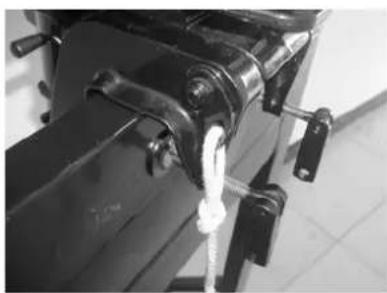
- If the engine restraint cable attachment is equipped on your engine, an engine restraint cable or chain should be used. Attach to a secure mounting point on the boat to avoid the engine being completely lost if it accidentally falls off the transom.
natural_image
Close-up of a mechanical component with a white rope tied to a black base (no visible text or symbols)- Secure the clamp bracket to the transom using the appropriate bolts. For details, consult your dealer.

WARNING:
Avoid using bolts, nuts or washers inappropriate. After tightening, test running the engine and check their tightness.
2.2 Breaking in engine
Your new engine requires a period of break-in to allow mating surfaces of moving parts to wear in evenly.
CAUTION:
Failure to follow the break-in procedure could result in reduced engine life or even severe engine damage.
- For the first hour of operation:
Run the engine at 2000 r/min or at approximately half throttle.
- For the second hour of operation:
Run the engine at 3000 r/min or at approximately three-quarter throttle.
- For the next eight hours of operation:
Avoid continuous operation at full throttle for more than five minutes at a time.
- Operate the engine normally.
2.3 Pre-operation checks
Fuel
- Check to be sure you have plenty of fuel for your trip.
● Make sure there are no fuel leaks or gasoline fumes. - Check fuel line connections to be sure they are tight.
- Be sure the fuel tank is positioned on a secure, flat surface, and that the fuel line is not twisted or flattened, or likely to contact sharp objects.
Controls
- Check throttle, shift and steering for proper operation before starting the engine.
● The controls should work smoothly, without binding or unusual free play. - Look for loose or damaged connections.
- Check operation of the starter and stop switches when the outboard motor is in the water.
CAUTION:
- Do not start the engine out of water. Overheating and serious engine damage can occur.
- Check the engine and engine mounting.
- Look for loose or damaged fasteners.
- Check the propeller for damage.
Checking the engine oil level
- Put the outboard motor in an upright position (not tilted).

- Check the oil level using the dipstick to be sure the level falls between the upper and lower marks. Fill with oil if it is below the lower mark, or drain to the speci ed level if it is above the upper mark.

natural_image
Close-up of a mechanical pump assembly with visible components and wiring (no text or symbols)-
Oil cap
-
Upper level mark
-
Oil dipstick
-
Lower level mark

CAUTION:
Be sure to completely insert the dipstick into the dipstick guide.

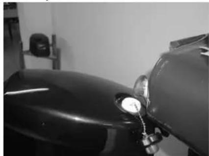
2.4 Filling fuel
Gasoline and its vapors are highly flammable and explosive. Keep away from sparks, cigarettes, flames, or other sources of ignition.
-
Remove the fuel tank cap.
-
Carefully fill the fuel tank.
natural_image
Close-up of a motorcycle's side mirror and handle, no visible text or symbols
natural_image
Close-up of a gray plastic container with a small valve attached, placed on tiled floor (no visible text or symbols)- Securely close the cap after filling the tank. Wipe up any spilled fuel.
NOTE:
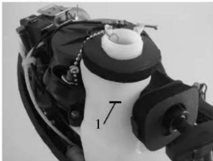
The upper fuel level mark is indicated on the built-in fuel tank.
natural_image
Close-up of a robotic arm with black and white components and labeled parts (no readable text or symbols)- Upper level mark
2.5 Starting engine
- Loosen the air vent screw on the fuel tank cap.
One turn for built-in tank; 2 or 3 turns for the external fuel tank.

natural_image
Close-up of a hand pressing down on a black surface, no visible text or symbols- Open the fuel cock.
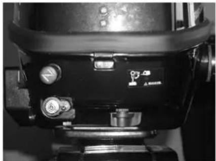
natural_image
Close-up of a camera lens component with adjustment knobs and a small logo (no readable text or symbols)Built in fuel tank

natural_image
Close-up of a camera lens component with no visible text or symbolsExternal fuel tank
- If you are using an external fuel tank, connect fuel joints securely and squeeze the primer pump with the outlet end up until you feel it become firm.
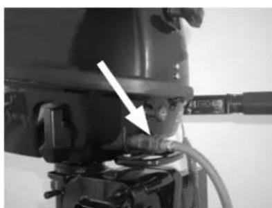
natural_image
Close-up of a mechanical component with a white arrow pointing to a feature, no visible text or symbols
natural_image
Close-up of a hand holding a black cable with a hose, against a plain background (no text or symbols visible)- Place the gear shift lever in neutral.

NOTE:
The start-in-gear protection device prevents engine from starting except when in neutral. Attach engine stop switch lanyard to secure place on your clothing, arm or leg. Attach lock tab, located on the other end lanyard, to the engine stop switch.
⚠ WARNING:
- The engine must be started in neutral, otherwise damage to engine can occur.
- Do not attach lanyard to clothing that could tear loose. Do not route lanyard where it could become entangled, preventing lanyard from functioning.
- Avoid accidentally pulling lanyard during normal operation. Loss of engine power means loss of steering control. Also, without engine power, the boat could slow rapidly. This could result in operator, passengers and/or objects in the boat to be thrown forward.

natural_image
Close-up of a hand holding a wristband with a white arrow pointing to the wrist area (no text or symbols visible)- Place the throttle grip in the "START"(start) position.
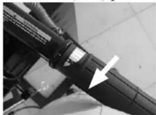
natural_image
Close-up of a mechanical component with a white arrow pointing to a detail (no visible text or symbols)- Pull out the choke knob fully.

natural_image
Close-up of a mechanical component with a white arrow pointing to a specific part (no visible text or symbols)NOTE:
- It is not necessary to use the choke when starting a warm engine.
-
If the choke is left in the “START” (start) position while the engine is running, the engine will run poorly or stall.
-
Pull the manual start handle slowly until you feel resistance. Then give a strong pull straight to crank and start the engine. Repeat if necessary.
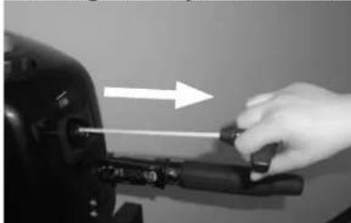
natural_image
Hand using a screwdriver to adjust a mechanical component (no text or symbols visible)16
- After the engine starts, slowly return the manual starter handle to its original position before releasing it.
- Slowly return the throttle grip to the fully closed position.
CAUTION:
- When the engine is cold, it needs to be warmed up.
- If the engine does not start on the first try, repeat the procedure. If the engine fails to start after 4 or 5 tries, open the throttle a small amount (between 1/8 and 1/4), and try again.
2.6 Warming up engine
- After starting the engine, return the choke knob to the halfway position. For approximately the first 5 minutes after starting, warm up the engine by operating at one fifth throttle or less. After the engine has warmed up, push the choke knob in fully.
CAUTION:
- If the choke knob is left pulled out after the engine starts, the engine will stall.
-
In the temperatures of -5°C or less, leave the choke knob pulled out fully for approximately 30 seconds after starting.
-
Check for steady flow of water from the cooling water pilot hole.

natural_image
Interior view of a vehicle or spacecraft with visible mechanical components and no text or symbolsCAUTION:
- If water is not flowing out of the hole at all times while the engine is running, stop the engine and check whether the cooling water inlet on the lower case or the cooling water pilot hole is blocked.
- If the problem cannot be located and corrected, consult your dealer.
2.7 Shifting

WARNING:
Before shifting, make sure there are no swimmers or obstacles in the water near you.
CAUTION:
To shift from forward to reverse or vice versa, first close the throttle so that the engine idles (or runs at low speeds).
2.7.1 Forward
- Place the throttle grip in the fully closed position.
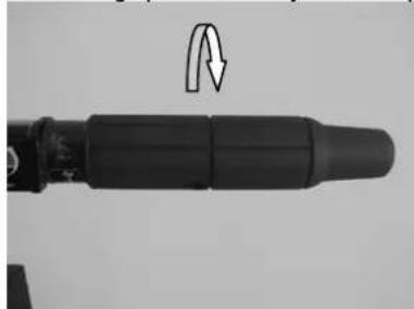
natural_image
Close-up of a mechanical component with a curved arrow indicating rotational motion (no text or symbols)- Move the gear shift lever quickly and firmly from neutral to forward.
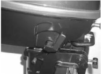
natural_image
Close-up of a mechanical component with no visible text or symbols2.7.2 Reverse

WARNING:
When operating in reverse, go slowly. Do not open the throttle more than half. Otherwise the boat could become unstable, which could result in loss of control and an accident.
- Place the throttle trip in the fully closed position.

natural_image
Close-up of a black cylindrical mechanical component with an arrow indicating rotation (no text or symbols visible)- Move gear shift lever quickly and firmly from neutral to reverse.
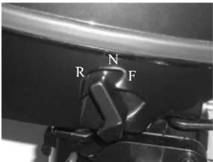
NOTE: The outboard motor can turn 360^ in its bracket (full-pivot system). The boat can also be backed up by simply turning the outboard motor 180^ .
2.8 Tiller
- Change direction To change direction, move the tiller handle to the left or right as necessary.

natural_image
Close-up of a mechanical lever with a black handle and white arrow indicator (no text or symbols)- Change speed.
Turn the grip counterclockwise to increase speed and clockwise to decrease speed.
- Throttle indicator
The throttle indicator is on the throttle grip. The fuel consumption curve on the throttle indicator shows the relative amount of fuel consumed for each throttle position. Choose the setting that offers the best performance and fuel economy for the desired operation.

natural_image
Close-up of a black mechanical component with labeled part '1' (no visible text or symbols)-
Throttle indicator
-
Throttle friction adjuster
The throttle friction adjuster is on the tiller handle, which provides adjustable resistance to movement of the throttle grip, and can be set according to operator preference.
To increase resistance, turn the adjuster clockwise. To decrease resistance, turn the
adjuster counterclockwise. When constant speed is desired, tighten the adjuster to maintain the desired throttle setting.

natural_image
Close-up of a black automotive component with a white arrow pointing to a section (no visible text or symbols)WARNING:
Do not over-tighten the friction adjuster. If there is too much resistance, it could be difficult to move throttle lever or grip, which could result in an accident.
2.9 Stopping engine
NOTE:
Before stopping the engine, first let it cool off for a few minutes at idle or low speed. Stopping the engine immediately after operating at high speed is not recommended.
- Remove engine stop lanyard to shut off engine.

natural_image
Close-up of a mechanical component with a white arrow pointing to a small feature (no visible text or symbols)NOTE:
If the outboard motor is equipped with an engine stop switch lanyard, the engine can also be stopped by pulling the lanyard and removing the lock plate from the engine stop switch.
- Tighten the air vent screw on the fuel tank cap and set the fuel cock lever or knob to the closed position.
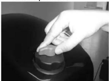
natural_image
Close-up of a hand pressing down on a black surface with a circular knob (no text or symbols visible)
natural_image
Close-up of a black electronic device with control buttons and a mounted base (no visible text or symbols)- Disconnect the fuel line if you are using an external fuel tank..

natural_image
Close-up of a hand adjusting a mechanical component with a white arrow pointing to it (no visible text or symbols)2.10 Trimming outboard motor
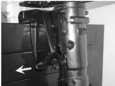
There are 4 or 5 holes provided in the clamp bracket to adjust the outboard motor trim angle.
-
Stop the engine.
-
Remove the trim rod from the clamp bracket while slightly tilting the outboard motor up.
natural_image
Close-up of a mechanical component with a white arrow pointing to a specific part (no visible text or symbols)- Reposition the rod in the desired hole. Make test runs with the trim set to different angles to find the position that works best for your boat and operating conditions.

WARNING:
- Stop the engine before adjusting the trim angle.
- Use care to avoid being pinched when removing or installing the rod.
- Use caution when trying a trim position for the first time. Increase speed gradually and watch for any signs of instability or control problems. Improper trim angle can cause loss of control.
Tilting up and down
If the engine will be stopped for some time or if the boat is moored in shallows, the outboard motor should be tilted up to protect the propeller and casing from damaged by collision with obstructions, and also to reduce corrosion.

WARNING:
- Be sure all people are clear of the outboard motor when tilting up and down, also be careful not to pinch any body parts between the drive unit and engine bracket.
● Tighten the air vent screw and place the fuel cock in the closed position if the outboard motor will be tilted for more than a few minutes. Otherwise fuel may leak.
NOTE:
- Do not tilt up the engine by pushing the tiller handle because this could break the handle.
- The outboard motor cannot be tilted when in reverse or when the outboard motor is turn 180^ (facing the rear).
2.11.1 Tilting up
- Place the gear shift lever in neutral (if equipped) and face the outboard motor forward.

natural_image
Close-up of a mechanical component with no visible text or symbols- Tighten the steering friction adjuster by turning it clockwise to prevent the motor from turning freely.

natural_image
Close-up of a mechanical component with a curved arrow indicating rotation or motion (no visible text or symbols)- Tighten the air vent screw. On models equipped with a fuel joint, disconnect the fuel line form the outboard motor.

natural_image
Close-up of a hand holding a small black knob on a dark surface (no text or symbols visible)
natural_image
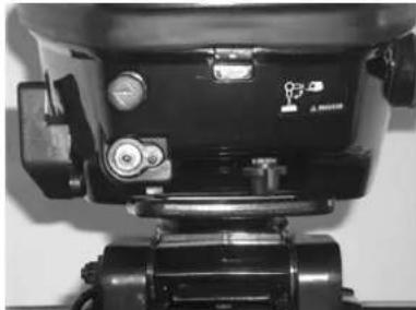
Close-up of a hand operating a mechanical component with a white arrow indicating direction (no visible text or symbols)- Close the fuel cock.
natural_image
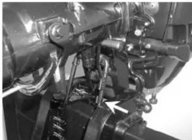
Close-up of a black mechanical device with adjustment knobs and a base mount (no visible text or symbols)- Hold the rear handle and tilt the engine up fully until the tilt support lever automatically locks.
natural_image
Close-up mechanical assembly showing hoses, springs, and a valve (no visible text or symbols)2.11.2 Tilting down
-
Slightly tilt the outboard motor up.
-
Slowly tilt the outboard motor down while pulling the tilt support bar lever up.

natural_image
Close-up mechanical assembly showing hoses and springs (no visible text or symbols)- Loose the steering friction adjuster by turning it counterclockwise, and adjust the steering friction according to operator preference.

natural_image
Close-up of a metallic mechanical component with a curved arrow indicating a motion or feature (no visible text or symbols)
WARNING:
If there is too much resistance it could be difficult to steer, which could result in an accident.
2.12 Cruising in other conditions
2.12.1 Cruising in shallow water
The outboard motor can be tilted up partially to allow operation in shallow water.

WARNING:
- The tilt lock mechanism does not work while the shallow water cruising system is being used. Run the boat at the lowest possible speed to avoid the outboard motor being lifted out of the water, resulting in loss of control.
- Return the outboard motor to its normal position as soon as the boat is back in deeper water.
CAUTION:
The cooling water inlet on the lower unit should be not above the surface of the water when setting up for and cruising in shallow water. Otherwise severe damage from overheating can result. For tilting procedure, see section 2.11.
2.12.2 Cruising in salt water
After operating in salt water, wash out the cooling water passages with fresh water to prevent them from becoming clogged with salt deposits.
3. Maintenance
While using the outboard motor, the periodic maintenance is necessary for you to ensure its performance.

WARNING:
Be sure to turn off the engine when you perform maintenance unless otherwise specified. This work should always be done by a qualified mechanic or your authorized dealer.
CAUTION:
If replacement parts are necessary, use only genuine parts or appropriate parts of the same type and quality.
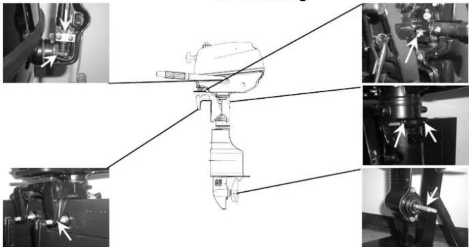
3.1 Greasing
natural_image
Technical diagram of a mechanical device with multiple views and arrows indicating assembly or component alignment (no text or symbols present)3.2 Cleaning and adjusting spark plug
You should periodically remove and inspect the spark plug because heat and deposits will cause the spark plug to slowly break down and erode. If necessary, you should replace the spark plug with another of the correct type.
Before fitting the spark plug, measure the electrode gap with a wire thickness gauge; adjust the gap to specification if necessary.

natural_image
Technical line drawing of a mechanical component with threaded ends and a pointed tip (no text or symbols)0.6-0.7mm
When fitting the plug, always clean the gasket surface and use a new gasket. Wipe off any dirt from the threads and screw in the spark plug to the correct torque.
3.3 Checking the fuel system
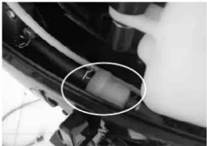
- Check the fuel lines for leaks, crack, or malfunction. If a problem is found, contact your dealer and have this repaired immediately.

natural_image
Industrial mechanical device with hoses and components, no visible text or symbols
natural_image
Exterior view of a gray rectangular electronic device with attached cables and connectors (no visible text or symbols)
WARNING:
- Check for fuel leakage regularly.
-
If any fuel leakage is found, the fuel system must be repaired by a qualified mechanic.
-
Check the fuel filter periodically. If foreign matter is found in the filter, replace it.
CAUTION:
The fuel filter is one piece, disposable spare part.
natural_image
Close-up of a mechanical component with a highlighted circular area, no visible text or symbols3.4 Inspecting idling speed
A diagnostic tachometer should be used for this procedure. Results may vary depending on whether testing is conducted with the flushing attachment, in a test tank, or with the outboard motor in the water.
- Start the engine and allow it to warm up fully in neutral until it is running smoothly.
- Verify whether the idle speed is set to specification.
Idle speed: 1500±50Rpm
CAUTION:
Correct idling speed inspection is only possible if the engine is fully warmed up. If not warmed up fully, the idle speed will measure higher than normal. If you have difficulty verifying the idle speed, or the idle speed requires adjustment, consult a dealer or other qualified mechanic.
3.5 Changing engine oil

WARNING:
- Avoid draining the engine oil immediately after stopping the engine. The oil is hot and should be handled with care to avoid burns.
- Be sure the outboard motor is securely fastened to the transom or a stable stand.
CAUTION:
Change the engine oil after the first 10 hours of operation, and every 100 hours or at 6-month intervals thereafter. Otherwise the engine will wear quickly.
CAUTION:
Change the engine oil when the oil is still warm.
-
Put the outboard motor in an upright position (not tilted).
-
Prepare a suitable container that holds a larger amount than the engine oil capacity. Loosen and remove the drain screw while holding the container under the drain hole. Then remove the oil filler cap. Let oil drain completely. Wipe up any spilled oil immediately.

natural_image
Close-up of a mechanical component with a highlighted circular feature and an arrow pointing to a specific part (no visible text or symbols)- Put a new gasket on the oil drain screw. Tighten the drain screw.
- Add the correct amount of oil through the filler hole. Install the filler cap.
- Start the engine and make sure that there are no oil leaks.
- Turn off the engine and wait 3 minutes. Recheck the oil level using the dipstick to be sure the level falls between the upper and lower marks.
CAUTION:
The oil should be changed more often when the engine is operated under adverse conditions such as extended trolling.
3.6 Checking wiring and connectors
Check that each grounding wire is properly secured and each connector is engaged securely.
3.7 Checking for leakage
Check that no exhaust or water leaks from the joints between the exhaust cover, cylinder head, and body cylinder.
Check for oil leaks around the engine.
CAUTION:
If any leaks are found, consult your dealer.
3.8 Checking propeller

WARNING:
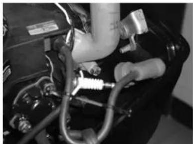
- Before inspecting, removing or installing the propeller, always take actions to ensure the engine does not accidentally start, such as removing the spark plug caps from the spark plugs, placing the shift control in neutral, and removing the lanyard from the engine stop switch, etc.. Serious injury can occur if the engine should start and you are standing too closeto the propeller.
- Do not use your hand to hold the propeller when loosening or tightening the propeller nut. Put a wood block between the anti-cavitation plate and the propeller to prevent the propeller from turning.
natural_image
Close-up of a mechanical or electrical component with hoses and tubing (no visible text or symbols)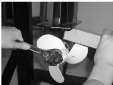
natural_image
Close-up of hands using a tool to lift a white propeller inside a mechanical device (no visible text or symbols)- Check each of the propeller blades for wear, erosion from cavitation or ventilation, or other damage.
-
Check the propeller shaft for damage.
-
Check the splines/shear pin for wear or damage.
- Check for fish line tangled around the propeller shaft.
- Check for the propeller shaft oil seal for damage.
3.8.1 Removing the propeller
- Straighten the cotter pin and pull it out using a pair of pliers.
- Remove the propeller nut, washer, and spacer (if equipped).
- Remove the propeller and thrust washer.
3.8.2 Installing the propeller
CAUTION:
- Be sure to install the thrust washer before instating the propeller, otherwise the lower case and propeller boss could be damaged.
-
Be sure to use a new cotter pin and bend the ends over securely. Otherwise the propeller could come off during operation and be lost.
-
Apply a marine grease or corrosion resistant grease to the propeller shaft.
-
Install the spacer (if equipped), thrust washer, and propeller on the propeller shaft.
-
Install the spacer (if equipped) and the washer.
- Tighten the propeller nut. Align the propeller nut with the propeller shaft hole. Insert a new cotter pin in the hole and bend the cotter pin ends.
3.9 Changing gear oil
WARNING:
- Be sure the outboard motor is securely fastened to the transom or a stable stand.
-
Never get under the lower unit while the outboard motor is tilted, even when the tilt support lever or knob is locked. Serious injury could occur if the motor falls.
-
Tilt the outboard motor so that the gear oil drain screw is at the lowest point possible.
- Place a suitable container under the gear case.
- Remove gear oil drain screw.

natural_image
Close-up of a propeller with two blades, labeled parts 1 and 2 (no text or symbols on the device itself)- Gear oil drain screw
- Oil level plug
CAUTION:
Change the gear oil after the first 10 hours of operation, and every 100 hours or at 6-month intervals thereafter. Otherwise the gear will wear quickly.
- Remove the oil level plug to allow the oil to drain completely.
CAUTION:
Inspect the used oil after it has been drained. If the oil is milky, water is getting into the gear case which can cause gear damage. Consult your dealer.
- Use a flexible or pressurized filling device, inject the gear oil into the gear oil drain screw hole.
- When the oil begins to flow out of the oil level plug hole, insert and tighten the oil level plug (If necessary, change the seal spacer).
- Insert and tighten the gear oil drain screw (If necessary, change the seal spacer).
3.10 Cleaning fuel tank
WARNING:
- Keep away from sparks, cigarettes, flames, or other sources of ignition when cleaning the fuel tank.
-
Cleaning the fuel tank in a well-ventilated open air.
-
Empty the fuel tank into an approved container.
-
Pour a small amount of suitable solvent into the tank. Install the cap and shake the tank. Drain the solvent completely.
- Pull the fuel joint assembly out of the tank.
- Clean the filter in a suitable cleaning solvent and allow it to dry.
- Replace the gasket with a new one. Reinstall the fuel joint assembly and tighten the screws firmly.
3.11 Checking and replacing anode(s)
Inspect the external anodes periodically. Remove scales from the surfaces of the anodes. Consult a dealer for replacement of external anodes.
CAUTION:
Do not paint anodes, as this would render them ineffective and can cause more rapid engine corrosion.

natural_image
Close-up of a hand holding a small object with an arrow pointing to it, next to a black panel (no visible text or symbols)3.12 Checking top cowling
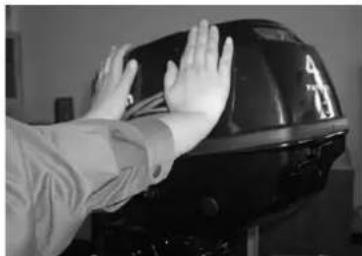
Check the fitting of the top cowling by pushing it with both hands. If it is loose have it repaired by your dealer.
natural_image
Person adjusting a black helmet with hands on the rim (no visible text or symbols)3.13 Maintenance table
When utilized under normal condition, maintained and repaired in the proper manner, the outboard motor can work normally within the normal life period.
Frequency of maintenance operations may be adjusted according to the operating conditions, but the following table gives general guidelines.
The “●” symbol indicates the check-ups which you may carry out by yourself.
The “○” symbol indicates work to be carried out by your dealer.
| Item | Operations | Initial | |||
| 10 hours( 1 month ) | 50 hours(3 months) | 100 hours(6 months) | 200 hours( 1 year ) | ||
| Anode(s) (external) | Check/replacement | ●/○ | ●/○ | ||
| Anode(s) (internal) Check/replacement ○ | |||||
| Cooling water passages | Cleaning | ● ● | |||
| Cowling clamp Check | ● | ||||
| Fuel filter (one time) | Check/cleaning | ●/○ | ●/○ | ●/○ | |
| Fuel system | Check | ● | ● | ● | |
| Fuel tank (built-in tank) | Check/cleaning | ○ | |||
| Fuel tank (portable tank) | Check/cleaning | ● | |||
| Gear oil | Change | ● | ● | ||
| Greasing points | Greasing | ● | |||
Every
Continuation /...1
| Item | Operations | Initial | Every | ||
| 10 hours( 1 month ) | 50 hours(3 months) | 100 hours(6 months) | 200 hours( 1 year ) | ||
| Idling speed(carburetor models) | Check/adjustment | ●/○ | ●/○ | ||
| Propeller and cotter pin | Check/replacement | ● | ● | ||
| Shift link/shift cable Check/adjustment ○ | |||||
| Thermostat | Check | ||||
| Throttle link/throttle cable/ throttle pick-up timing | Check/adjustment | ○ | |||
| Water pump | Check | ||||
| Engine oil | Check/replacement | ● | ● | ||
| Spark plug (s) | Cleaning/adjustment/ replacement | ● | ● | ||
| Valve clearance (OHC, OHV) | Check/adjustment | ○ | ○ | ||
NOTE:
When operating in salt water, turbid or muddy water, the engine should be flushed with clean water after every use.
4 Transporting and storing
4.1 Transporting
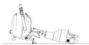
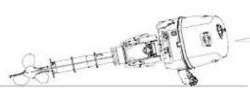
The outboard motor should be upright as shown in the following figure 1 when be in transit. If the engine must be laid down, please be sure to put it as shown in the following figure 2 or figure 3 when be in transit.
CAUTION:
Do not use the tilt support lever or knob when trailering the boat. The outboard motor could shake loose from the tilt support and fall. If the motor cannot be trailered in the normal running position, use an additional support device to secure it in the tilt position.
! WARNING:
- Never get under the lower unit while it is tilted, even if a motor support bar is used.
- Please put the outboard motor as shown figures below when transporting it.

Figure 1
natural_image
Line drawing of a mechanical device with no visible text or symbolsFigure 2
natural_image
Technical line drawing of a mechanical assembly with no visible text or symbols
natural_image
Line drawing of a mechanical device inside a circular frame, labeled 'Figure 3' (no text or symbols on the diagram itself)Figure 3
Note:
- Place a towel or something similar under the outboard motor to protect it from damage when as shown in the figure 2 or figure 3 above.
- Please make sure the tiller handle faces down to make the throttle handle point to the direction of propeller.
4.2 Storing
When storing your outboard motor for prolonged periods of time (2 months or longer), several important procedures must be performed to prevent excessive damage.
CAUTION:
- Keep the outboard motor in an upright attitude when storing it. If storing the outboard motor on its side (not upright), put it on a cushion after draining the engine oil completely.
- Do not place the outboard motor on its side before the cooling water has drained from it completely.
- Store the outboard motor in a dry, well-ventilated place, not in direct sunlight.
It is advisable to have your outboard motor serviced by an authorized dealer prior to storage. However, you, the owner, with a minimum of tools, can perform the following procedures.
- Wash the outboard motor body using fresh water.
- Place the fuel cock in the closed position, disconnect the fuel line and tighten the air vent screw, if equipped.
- Remove the engine top cowling and silencer cover.
- Install the outboard motor on the test tank.

- Lowest water level
-
Water surface
-
Fill the tank with fresh water to above the level of the anti-cavitation plate.
CAUTION:
If the fresh water level is below the level of the anti-cavitation plate, or if the water supply is insufficient, engine seizure may occur.
- Start the engine. Flush the cooling system. Perform the flushing and fogging at the same time, as fogging/lubricating of the engine is mandatory to prevent engine rust.

WARNING:
- Do not touch or remove electrical parts when starting or during the operation.
-
Keep hands, hair, and clothes away from the flywheel and other rotating parts while the engine is running.
-
Run the engine at a fast idle for a few minutes in neutral position.
-
Just prior to turning off the engine, quickly spray "Fogging Oil" alternately into each carburetor or the fogging hole of the silencer cover, if equipped.
-
If "Fogging Oil" is not available, run the engine at a fast idle until the fuel system empties and the engine stops.
-
If "Fogging Oil" is not available, remove the spark plug(s). Pour a teaspoonful of clean engine oil into each cylinder. Crank several times manually. Replace the spark plug(s).
-
Drain the fuel from the fuel tank completely.
CAUTION:
Portable fuel tank equipped models: Store the portable fuel tank in a dry, well-ventilated place, not in direct sunlight.
5 Actions in emergency
5.1 Impact damage
If the outboard motor hits an object in the water, follow the procedure below.
- Stop the engine immediately.
- Inspect the control system and all components for damage.
- Whether damage is found or not, return to the nearest harbor slowly and carefully.
- Have a dealer inspect the outboard motor before operating it again.
5.2 Starter will not operate
If the starter mechanism does not operate, the engine can be started with an emergency starter rope.
WARNING:
- Use this procedure only in an emergency and only to return to port for repairs.
- When the emergency starter rope is used to start the engine, the start-in-gear protection device does not operate. Make sure the remote control lever is in neutral.
- Be sure no one is standing behind you when pulling the starter rope. It could whip behind you and injure someone.
- Do not install the starter mechanism or top cowling after engine is running. Keep loose clothing and other objects away when starting the engine. Do not touch the flywheel or other moving partswhen the engine is running.
- Do not touch the ignition coil, spark plug wire, spark plug cap, or other electrical components when starting or operating the motor.
The procedure is as follows:
-
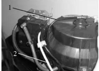
Remove the top cowling.
-
Remove the start-in-gear protection cable and the choke cable.
natural_image
Close-up of a mechanical device with labeled parts (1 and 2), showing hoses and components without any readable text or symbols.- Start-in-gear protection cable
-
Choke cable
-
Remove the starter after removing the three bolts.

natural_image
Close-up of a mechanical device with visible components and directional arrows (no readable text or symbols)- Reinstall two bolts to secure the fuel tank.

natural_image
Close-up of a person operating a mechanical device with no visible text or symbols-
Prepare the engine for starting. For further information, see section 2.5.
-
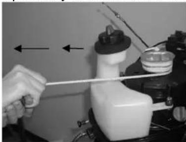
Insert the knotted end of the emergency starter rope into the notch in the flywheel rotor and wind the rope several turns around the flywheel clockwise.
-
Pull the rope slowly until resistance is felt.
natural_image
Close-up of a hand using a tool to adjust or install a white plastic bottle (no visible text or symbols)- Give a strong pull straight out to crank and start the engine. Repeat it necessary.
5.3 Treatment of submerged motor
If the outboard is submerged, immediately take it to a dealer. Otherwise some corrosion may begin almost immediately.
-
Thoroughly wash away contaminants with fresh water.
-
Remove the spark plug(s), then face the spark plug hole downward to allow any mud, or contaminants to drain.
-
Drain the fuel from the carburetor, fuel filter, and fuel line. Drain the engine oil completely.

natural_image
Close-up of a mechanical component with a curved pipe and valve, no visible text or symbols-
Fill the sump with fresh engine oil.
-
Feed engine fogging oil or engine oil through the carburetor(s) and spark plug holes while pulling the start cord to the engine.

natural_image
Close-up of a car engine bay with visible hoses and components, no text or symbols present- Take the outboard motor to a COLEMAN outboard service center as soon as possible.
CAUTION:
Do not attempt to run the outboard motor until it has been completely inspected.
- Troubleshooting
| Trouble type | Possible reason Recovery action | |
| operate | Starter components are faulty Have serviced | by your dealer Starter will not |
| Shift level is not in neutral Shift to neutral | ||
| Engine will not start (starter operates) | Fuel tank is empty Fill tank with clean, fresh fuel | |
| Fuel is contaminated or stale Fill tank with clean, fresh fuel | ||
| Fuel filter clogged Replace with recommended type | ||
| Fuel pump has malfunctioned Have serviced | by your dealer | |
| Spark plug(s) fouled or of incorrect type. | Inspect spark plug(s). Clean or replace with recommended type | |
| Spark plug cap(s) fitted incorrectly Check and re-fit cap(s) | ||
| Ignition wiring damaged or poorly connected | Check wires for wear or breaks.Tighten all loose connections.Replace worn or broken wires | |
| Ignition parts are faulty Have serviced by your dealer | ||
| Engine stop switch lanyard is not attached Attach lanyard | ||
| Engine inner parts are damaged Have serviced by your dealer | ||
| Engine idles irregularly or stalls | Spark plug(s) fouled or of incorrect type. | Inspect spark plug(s). Clean or replace with recommended type |
Continuation /...1
| Trouble type Possible reason Recovery action | ||
| Engine idles irregularly or stalls | Fuel system is obstructed | Check for pinched or kinked fuel line or other obstructions in fuel system |
| Fuel is contaminated or stale Fill tank with clean, fresh fuel | ||
| Fuel filter clogged Replace with recommended type | ||
| Spark plug gap is incorrect Inspect and adjust as specified | ||
| Ignition wiring damaged or poorly connected | Check wires for wear or breaks.Tighten all loose connections.Replace worn or broken wires | |
| Specified engine oil is not being used Check and replace oil as specified | ||
| Thermostat is faulty or clogged Have serviced by your dealer | ||
| Carburetor adjustments are incorrect Have serviced by your dealer | ||
| Carburetor is clogged Have serviced by your dealer | ||
| Fuel pump is damaged Have serviced by your dealer | ||
| Air vent screw on fuel tank is closed Open air vent screw | ||
| Fuel joint connection is incorrect Connect correctly | ||
| Throttle valve adjustment is incorrect Have serviced by your dealer | ||
| Choke knob is pulled out Return to home position | ||
| Motor angle is too high | Return to normal operating position | |
Continuation /...2
| Trouble type Possible reason Recovery action | ||
| Engine power loss | Propeller is damaged Repair or replace propeller | |
| Trim angle is incorrect | Adjust trim angle to achieve most efficient operation | |
| Motor is mounted at incorrect transom height | Adjust motor to proper transom height | |
| Boat bottom is fouled with marine growth Clean boat bottom | ||
| Weeds or other foreign matter are tangled on gear housing | Remove foreign matter and clean lower unit | |
| Spark plug(s) are fouled or incorrect type | Inspect spark plug(s). Clean or replace with recommended type | |
| Fuel system is obstructed | Check for pinched or kinked fuel line or other obstructions in fuel system | |
| Fuel filter is clogged Replace with recommended type | ||
| Fuel is contaminated or stale Fill tank with clean, fresh fuel | ||
| Spark plug gap is incorrect Inspect and adjust as specified | ||
| Ignition wiring is damaged or poorly connected | Check wires for wear or breaks. Tighten all loose connections. Replace worn or broken wires | |
| Ignition parts have failed Have serviced by your dealer | ||
| Specified engine oil is not being used Check and replace oil as specified | ||
Continuation /...3
| Trouble type | Possible reason Recovery action | |
| Engine power loss | Thermostat is faulty or clogged Have serviced by your dealer | |
| Air vent screw on fuel tank is closed Open air vent screw | ||
| Fuel pump has malfunctioned Have serviced by your dealer | ||
| Fuel joint connection is incorrect Connect correctly | ||
| Specified spark plug(s) are not being used | Check and replace spark plug(s) as specified | |
| Engine vibrates excessively | Propeller is damaged Repair or replace propeller | |
| Propeller shaft is damaged Have serviced by your dealer | ||
| Weeds or other foreign matter are tangled on propeller | Remove and clean propeller | |
| Motor mounting bolt is loose Tighten bolt | ||
| Steering pivot is loose Tighten it | ||
| Steering pivot is damaged Have serviced by your dealer | ||
- Circuit diagram


OUTBOARD MOTORS
9820 E. Thompson Peak Pkwy. Unit #837
Scottsdale, Arizona, 85255
colemanoutboards.com
Phone: 888-405-8725 - Fax: 800-379-0385
- Owner's Manual
- Model: F5BM
- YOUR COLEMAN OUTBOARD MOTOR
- Engine Identification Numbers
- Outboard motor serial number:
- Engine serial number
- Manufacturer's Declaration
- COLEMAN LIMITED WARRANTY
- The Warranty
- What is a Defect?
- To qualify for this warranty the part:
- Limitations of this Warranty
- COLEMAN/PARSUN - EMISSIONS CONTROL SYSTEM WARRANTY STATEMENT YOUR WARRANTY RIGHTS AND OBLIGATIONS
- OWNER'S WARRANTY RESPONSIBILITIES
- EXCLUSIONS AND LIMITATIONS
- WARRANTY COVERAGE
- LIMITED LIABILITY
- ! WARNING
- WARNING
- CAUTION:
- NOTE:
- Table of contents
- Main components and General information 1.1 Main components
- General information
- Specifications
- Fueling instructions
- WARNING:
- Propeller selection
- Operation
- Installation
- Mounting height
- Clamping the outboard motor
- Breaking in engine
- Pre-operation checks
- Fuel
- Controls
- Checking the engine oil level
- Filling fuel
- Starting engine
- ⚠ WARNING:
- Warming up engine
- Shifting
- Forward
- Tiller
- Stopping engine
- Trimming outboard motor
- Tilting up and down
- Tilting up
- Tilting down
- Cruising in other conditions
- Cruising in shallow water
- Cruising in salt water
- Maintenance
- Cleaning and adjusting spark plug
- Checking the fuel system
- Inspecting idling speed
- Changing engine oil
- Checking wiring and connectors
- Checking for leakage
- Checking propeller
- Removing the propeller
- Installing the propeller
- Changing gear oil
- Cleaning fuel tank
- Checking and replacing anode(s)
- Checking top cowling
- Maintenance table
- Transporting and storing
- Transporting
- ! WARNING:
- Storing
- Actions in emergency
- Impact damage
- Starter will not operate
- Treatment of submerged motor
Brand : COLEMAN
Model : F5BM
Category : Outboard motor