V-R841DP-AFHD - Monitor Marshall Electronics - Free user manual and instructions
Find the device manual for free V-R841DP-AFHD Marshall Electronics in PDF.


| Product Type | Portable High Definition LCD Monitor |
| Brand / Model | Marshall Electronics V-R841DP-AFHD |
| Screen Size | 8.4" diagonal |
| Native Resolution | 1024 x RGB x 768 (2.4 million pixels) |
| Aspect Ratio | 4:3 native (supports 4:3 and 16:9 modes) |
| Brightness | 400 cd/m² |
| Contrast Ratio | 400:1 |
| Viewing Angle | 170° horizontal / 170° vertical |
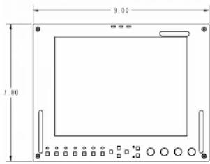
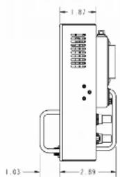
| Dimensions (W x H x D) | 9.00" x 7.00" x 1.87" |
| Weight (Monitor Only) | 3.4 lbs |
| Power Consumption | 2A @ 12VDC (24W) |
| Power Input | 12VDC via 4-pin XLR (V-Mount battery or AC adapter) |
| Video Inputs | Composite (BNC), S-Video (4-pin Mini-DIN), YPbPr (3x BNC), SDI (BNC), VGA (HD-15), DVI-D (29-pin) |
| Video Outputs (Active Loop-Through) | Composite (BNC), S-Video (4-pin Mini-DIN), YPbPr (3x BNC), SDI (BNC) |
| Supported Video Formats | NTSC, PAL, 480i/p, 576i/p, 720p, 1035i, 1080i/p, VESA up to SXGA (1280x1024) |
| Color Temperature Presets | D55 (5500K), D65 (6500K), D93 (9300K), User adjustable |
| On-Screen Markers | 16:9 and 4:3 markers (safe areas, aspect ratios), center marker, marker backgrounds |
| User-Definable Function Buttons | 2 buttons assignable to delay, aspect ratio, markers, monochrome, color temp, Pixel-to-Pixel, etc. |
| Special Modes | Monochrome, Blue-Only, Pixel-to-Pixel, Underscan, H/V Delay |
| Tally Lights | 3 LEDs (Green, Red, Yellow) controlled via HD-15 connector |
| Mounting | 1/4"-20 mounting bracket (bottom, removable); optional desktop stand or 19" rack adapter |
| Operating Temperature | 32°F to 120°F (0°C to 50°C) |
| Storage Temperature | -4°F to 120°F (-20°C to 50°C) |
| Compliance | FCC Class A, ANSI 63.4, RoHS compliant |
| Warranty | 1 year from purchase date (proof of purchase required) |
| Optional Accessories | IDX V-Mount batteries and chargers, battery adapters, power cables, stands, sun hood, cleaning wipes |
| Maintenance | Clean screen with ammonia-free wipes or microfiber cloth; dust with soft damp cloth |
Frequently Asked Questions - V-R841DP-AFHD Marshall Electronics
User questions about V-R841DP-AFHD Marshall Electronics
0 question about this device. Answer the ones you know or ask your own.
Ask a new question about this device
Download the instructions for your Monitor in PDF format for free! Find your manual V-R841DP-AFHD - Marshall Electronics and take your electronic device back in hand. On this page are published all the documents necessary for the use of your device. V-R841DP-AFHD by Marshall Electronics.
USER MANUAL V-R841DP-AFHD Marshall Electronics
Marshall Electronics
V-R841DP-AFHD
Portable High Definition LCD Monitor
natural_image
Line drawing of a rectangular electronic device with ports and connectors (no text or symbols)Operating Instructions
Marshall Electronics, Inc.
1910 East Maple Ave.
Tel: (900) 800-6608 / (310) 333-0606 · Fax: 310-333-0688
www.LCDRacks.com sales@cdracks.com
Ver. 2010-0216
Warranty
Marshall Electronics warranties to the first consumer that this V-R841DP-AFHD LCD monitor will, under normal use, be free from defects in workmanship and materials, when received in its original container, for a period of one year from the purchase date. This warranty is extended to the first consumer only, and proof of purchase is necessary to honor the warranty. If there is no proof of purchase provided with a warranty claim, Marshall Electronics reserves the right not to honor the warranty set forth above. Therefore, labor and parts may be charged to the consumer. This warranty does not apply to the product exterior or cosmetics. Misuse, abnormal handling, alterations or modifications in design or construction void this warranty. It is considered normal for a minimal amount of pixels, not to exceed three, to fall on the periphery of the display active viewing area. Marshall Electronics reserves the option to refuse service for display pixel failure if deemed unobtrusive to effective use of the monitor by our technicians. No sales personnel of the seller or any other person is authorized to make any warranties other than those described above, or to extend the duration of any warranties on behalf of Marshall Electronics, beyond the time period described above. Due to constant effort to improve products and product features, specifications may change without notice.
07/17/07
Optional Accessories
■ Batteries
- IDX-E7S 71Wh/4.8Ah Lithium Ion V-Mount Battery Pack
- IDX-E7 71Wh/4.8Ah Lithium Ion V-Mount Battery Pack with PowerLink
- IDX-E10S 98Wh/6.6Ah Lithium Ion V-Mount Battery Pack
- IDX-E10 98Wh/6.6Ah Lithium Ion V-Mount Battery Pack with PowerLink
■ Battery Chargers
- IDX-VL-2 Plus 2-Channel Sequential Multi-Format V-Mount Quick Charger/Power Supply
- IDX-VL-4S 4-Channel Simultaneous V-Mount Quick Charger
■ Battery Adapters
• V-ABA-01 Anton Bauer to IDX Battery Adapter Plate
■ Power Adapter Cables
• V-PAC-D-XLR 4-Pin XLR Male to Anton Bauer PowerTap Cable (3 ft.)
• V-PAC-XLR-1 4-Pin XLR Male to 4-Pin XLR Female Cable (3 fL)
■ Stands, Adapters, and Mounts
• VP-0113-DS-A Fixed Desktop Stand
• VP-0113-PM-B 19" Rack Adapter for up to 2 Monitors (4RU)
• V-LCD70TMB-02 Set of 3 1/4"-20 Tripod Mounting Brackets
• V-DG1105 Noga 8.3" Articulating Arm (¼"-20 to ½"-20). Holds up to 4.5 lbs.
• V-MG11043 Noga 9.7° Articulating Arm (3/8° to ¼°-20). Holds up to 7.5 lbs.
• V-LP-SLDSHOE1/4 Slide-Shoe Adapter with Nut, for Noga Articulating Arm
- V-LP-SLDSHOEBLOCK Slide-Shoe Block (Required with V-LP-SLDSHOE1/4)
- V-LP-SLDSHOENUT Extr. Slide Shop Not for V-MG14012 in Slide Shop
• V-LF-SLDSHOENUT Extra Slide-Shoe Nut for V-MGT1043 in Slide-Shoe Configuration
• V-VP-TBRKT Expansion T-bracket (3/4-20 and 3/8' holes)
■ Sun Hoods
• V-H900
Sun Hood for 8.4" Monitors
■ Cleaning Accessories
• V-HWP-K
Package of 10 Cleaning Wipes for LCD Displays
Visit www.LCDRacks.com for more information and additional accessories
Contents
Product Overview....4
Features 4
installation and Initial Setup .... 5
Unpacking 5
Installation....5
Connections and Power-On....5
Front Panel Features 6
Power Button 6
Input Select Buttons....6
On-Screen Menu Navigation Buttons 6
User-Definable Function Buttons 5
User-Definable Function Buttons ....6
Image Adjustment Kosha ....6
Tally Lights 6
Rear Panel Features....7
Power Input 7
Signal Input/Output 7
Tally Interface 7
Mounting Hole 7
Compatible Input Formats....8
On-Screen Menu....9
STRUCTURE OVERVIEW 9
MAIN MENU AND NAVIGATION 9
MARKER SETUP SUBMENU 10
16.9 Markers.... 10
4.2 Medium.... 41
4.3 Markers......11
Marker Background......11
Marker Background 11
Center Marker 11
VIDEO CONFIGURATION SUBMENU 12
Color Temperature Presels 12
Adjusting Color Bias 12
Adjusting Color Gain 12
Monochrome Mode....13
Blue Only Mode 13
Dival to DivalTM Motor 42
Pixel-to-Pixel™ Mode 13
Angel Poly Soling 14
Aspect Ratio Setting 14
Scanning Modes 14
Delay Modes 14
SYSTEM CONFIGURATION SUBMENU 15
Internal SMPTE Color Bars 15
User-Definable Function Buttons 15
Status Display....15
Saving and Loading User Configuration Presets 15
Specifications....16
Maintenance....17
Optional Accessories 18
Warranty 19
Product Overview
Specifications (continued)
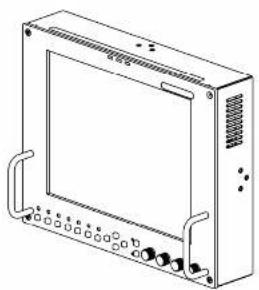
The V-R841DP-AFHD is a 8.4" high definition LCD monitor featuring our completely digital TFT-MegaPixel™ active matrix LCD platform. Weighing only 3.4 lbs, this monitor is ideal as a light-weight high resolution viewfinder or focus-assist monitor. The V-R841DP-AFHD can also be rack-mounted with an optional 4RU adapter, or used in a desktop configuration with optional desktop stand. Emulation of SMPTE-C/EBU color and adjustable color temperature enable the most precise color representation possible. Our proprietary digital signal processing features 10-bit A/D conversion of all analog signals, with 4X over-sampling and 5-line super-adaptive 2D comb filtering of composite signals. De-interlacing is performed using our HyperProcess ^19 algorithm with motion adaptive interpolation. Multi-format compatibility accommodates virtually all video formats including NTSC/PAL, 480ip, 720p, and 1060ip standards. VGA and DVI inputs accept VESA standards allowing the display to be used as a computer monitor. Advanced features include aspect ratio settings, a variety of screen markers, underscan mode, blue-only mode, monochrome mode, HV delay, and Pixel-to-Pixel ^19 mode.
Features
■ High-Resolution 8.4" Panel
The V-R841DP-AFHD features an all-digital TFT-MegaPixel™ active matrix LCD system with 2.4 million pixels. The LCD panel features a brightness of 400 cpl/100:1 contrast ratio, and a 170° all-around viewing angle making the display ideal in a variety of environments and lighting conditions.
■ Multi-Format Compatibility
With a variety of analog and digital inputs, the V-R841DP-AFHD accommodates virtually all video formats. Input types include Composite Video, S-Video, YPbPr, SDI, VGA, and DVI with HDCP. Accepted formats include NTSC/PAL, 450i/p, 576i/p, 720p, 1035i, and 1080i/p standards, as well as VESA PC formats through SXGA (1280 x 1024).
■ End-to-End Digital Signal Processing
Analog signals are digitized using an advanced 10-bit process with 4x over-sampling, 5-line super-adaptive 2D comb filtering, and exacting color space conversion. Video is scaled to fit on the screen in the highest possible resolution using a state-of-the-art LSI that incorporates precision gamma correction and our HyperProcess ^™ motion adaptive interpolation for Interlaced Images.
■ ColorMatch™ Conversion with Color Temperature Adjustment
Emulation of SMPTE-C/EBU color space allows the V-R841DP-AFHD to replace any broadcast CRT monitor. Settings include D55, D65 and D95. Bias and Gain adjustment for each color enables precise color matching and white balance.
■ Advanced Features
Aspect ratio settings, underscan mode, blue-only mode, monochrome mode, and H/V delay are a few of the advanced features making the V-R841DP-AFHD at home in any broadcast environment. Pixel-to-Pixel™ mode also allows native display of any Incoming Image format.
■ Flexible Screen Markers
A variety of screen markers in both 4.3 and 16.9 modes allow accurate monitoring of the different aspect ratios used in broadcast environments.
■ User-Definable Function Buttons
Two user-assignable function buttons on the front-panel allow quick access to numerous settings and features including aspect ratio, screen markers, monochrome mode, color temperature, delay mode, and more.
natural_image
Front view of an electronic device panel with ports, connectors, and wiring (no visible text or symbols)Maintenance
■ Screen Cleaning
Periodically clean the screen surface using ammonia-free cleaning wipes (Marshall Part No. V-HWP-K). A clean microfiber cloth can also be used using only non-abrasive and ammonia-free cleaning agents. Do not use paper towels. Paper towel fibers are coarse and may scratch the surface of the polycarbonate faceplate or leave streaks on the surface. Antistatic and fingerprint resistant cleaning agents are recommended. Do not apply excessive pressure to the screen to avoid damaging the LCD.
■ Faceplate Dusting
Dust the unit with a soft, damp cloth or chamols. Dry or abrasive cloths may cause electrostatic charge on the surf attracting dust particles. Neutralize static electricity effects by using the recommended cleaning and polishing practice.
Specifications
■ PANEL
Screen Size 8.4" Diagonal
Display Area (h x v) 170.469 x 127.672 mm
Aspect Ratio 4:3 Native (4:3/16:9 Modes)
Pixels 1024 x RGB x 768
Color Depth 24-bit (16,777,216 Colors)
Viewing Angle (h x v) 170° x 170
Brightness 400 cd/m
Contrast Ratio 400:1
Dot Pitch (h x v) 0.0555 x 0.1665 mm
Pixel Pitch (h x v) 0.1665 x 0.1665 mm
Pixel Response 25 ms (rise + fall)
Supports SMPTE 170M, NTSC/PAL
S-Video (Y/C) Input / Output
Supports SMPTE 170M, NTSC/PAL
YP_RP_R Input / Output
Supports SMPTE 280M, 274M, 296M
HD-SDI Input / Output
Supports ITU-R BT.656, SMPTE 259M, 292M
VGA Input
Supports RGBHV, RsGsBs, RGsB, RGB CS,
DVI Input
Supports Digital Signals Only (DVI-D)
HDMI, HDCP Supported
■ CONNECTORS
Video Input
Video 1 x BNC Female (75 Ω)
S-Video (Y/C) 1 x 4-Pin Mini-DIN
YP_3PR 3 x BNC Female (75 Ω)
HD-SDI 1 x BNC Female (75 Ω)
VGA 1 x HD-15 Female
DVI 1 x DVHI 29-Pin Female
Video Output (Active Loop-Through)
Video 1 x BNC Female (75 Ω)
S-Video (Y/C) 1 x 4-Pin Mini-DIN
YP_3PR 3 x BNC Female (75 Ω)
SDI
Power Input
4-Pin XLR Male
Tally Interface
HD-15 Female
■ TALLY
3 LEDs (Green, Red, Yellow). Activation requires contact closure of pin to ground on the HD-15 connector:
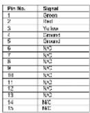
ELECTRICAL
Power Consumption 2A @ 12VDC (24 W) Voltage Requirement 12 VDC
V-PS12-5V-XLR Power Supply: Input 100V-240V, 1.5A, 50-60Hz Output 12VDC, 5A, 60W Max
V-Mount Battery Adapter (Accepts standard 12V / 14.4V V-Mount Batteries)
MECHANICAL
Dimensions (w x h x d): 9.00" x 7.00" x 1.87"
Additional Mounting: Desktop Stand and Rack Adapter Available
Weight (Monitor Only): 3.4 lbs Operating Temperature 32°F to 120°F (0°C to 50°C) Storage Temperature -4°F to 120°F (-20°C to 50°C)
Compliance 4. FCC-Class A, ANSI-63.4
(Certificates on file)
RoHa Do not dispose. Return to Manufacturer or Authorized Recycle Facility.
Installation and Initial Setup
■ Unpacking
Carefully unpack the V-R841DP-AFHD monitor and verify that the following items are included:
• V-R841DP-AFHD Monitor
• V-PS12-5V-XLR Power Supply with 4-Pin XLR Connector
- Operating Instructions
Inspect the unit for any physical damage that may have occurred during shipping. Should there be any damage, immediately contact Marshall Electronics at (800) 800-6608. If you are not located within the continental United States, call +1 (310) 333-0606.
■ Installation
The V-R841DP-AFHD monitor is shipped with a 14 "-20 mounting bracket on the bottom side, allowing the monitor to be flexibly mounted to a camera or other device using a variety of mounts. This 14 "-20 mounting bracket can also be attached to any side of the monitor.
Alternately, the V-R841DP-AFHD can be used in a desktop configuration with optional stand (Marshall part number VP-0113-DS-A), or mounted in 19" inch rack with optional adapter (Marshall part number VP-0113-PM-B).
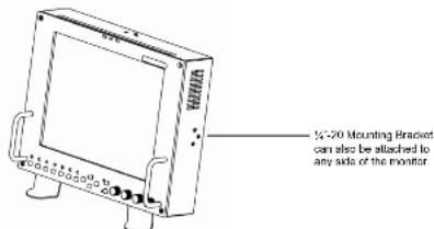
V-R841DP-AFHD with optional desktop stand
■ Connections and Power-On
Plug the V-PS12-5V-XLR power supply into an AC power source (100-240 V @ 50/60 Hz). Attach the 4-pin XLR connector to the back of the monitor. Please note that 12VDC can be also supplied directly to the monitor from a variety of sources. The monitor will draw approximately 2 Amps at 12 Volts in operation.
Connect the required cables for video signal input and output. (Power must be applied to the V-R841DP-AFHD for the active loop-though outputs to be activated.) All BNC connectors are rated at 75Ω.
Turn on the unit by pressing the power button located on the front panel. Select a video input by pressing the corresponding input select button.
Front Panel Features

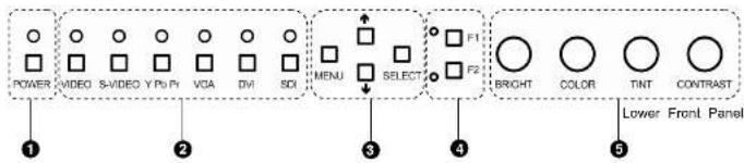
① Power Button
Turn the monitor on by pressing the power button. In the OFF state, the LED will shine red. The LED will shine green when the monitor is turned on.
② Input Select Buttons
Use the input select buttons to select the input to be displayed:
- Video
• S-Video - YPbPr (SD/HD)
• VGA
• DVI - SDI (SD/HD)
Each input automatically detects the applicable formats (See Compatible Input Formats – Page 8).
3 On-Screen Menu Navigation Buttons
Use the Menu, ↑, ↓, and Select buttons to display and navigate the on-screen menu (See Main Menu and Navigation – Page 9).
4 User-Definable Function Buttons
Two user-definable function buttons can be used for direct access to various settings. Functions are assigned using the on-screen menu (See User-Definable Function Buttons – Page 15).
⑤ Image Adjustment Knobs
Use the image adjustment knobs to adjust the following settings. Pressing each knob will display the current status of the corresponding control:
Three tally LEDs (green, red, and yellow) are provided as general purpose indicators. Each LED can be individually controlled, providing multiple indications. Tally LEDs are controlled via the HD-15 connector on the rear panel (See Tally Interface – Page 7)
On-Screen Menu (continued)
Use to display internally generated SMPTE split-field color bars.
■ User-Definable Function Buttons
Use the FUNCTION 1 and FUNCTION 2 menu items to define each function button on the front panel of the monitor. The following options are available for each button:
- DELAY Enable and rotate amongst delay modes.
• RATIO Toggle between 4:3 and 16:9 aspect ratios. - BACK Rotate amongst marker backgrounds.
- CENTER Enable/disable center marker.
- MARKER Enable and rotate amongst marker settings (choices depend on aspect ratio setting).
• MONO Enable/disable monochrome mode.
• CTEMP Rotate amongst color temperature settings. - PTP Enable/disable Pixel-to-Pixel™ mode.
FUNCTION 1 is set to RATIO by default.
FUNCTION 2 is set to PTP by default
■ Status Display
Use to enable on-screen display of input/format status in the upper-left corner of the screen.
■ Saving and Loading User Configuration Presets
Use the SAVE CONFIG and LOAD CONFIG menus to save current settings to one of 6 presets, or load a preset monitor settings on the monitor are saved, including the image adjustment knob settings.
- Use the LOAD CONFIG menu to load one of presets USR1 – USR6. Factory default settings can also be loaded by selecting MFG. (Factory defaults cannot be overwritten)
• Use the SAVE CONFIG menu to save the current settings to a preset from USR1-USR6.
On-Screen Menu (continued)
VIDEO CONFIGURATION SUBMENU (continued)
■ Aspect Ratio Settings
Use to switch between 4:3 and 16:9 aspect ratios.
As the V-R841DP-AFHD monitor has a native resolution of 1024 x 758 RGB pixels, incoming images are automatically scaled to fit the screen:
• In 4:3 mode, images are scaled up or down to fill the entire 4:3 screen (1024 x 766).
In 16:9 mode, images are scaled to fill the maximum 16:9 portion of the screen (1024 x 576), with black bars filling the remainder of the screen.
Note: The aspect ratio setting is ignored when Pixel-to-Pixel ^TM mode is enabled.
■ Scanning Modes
Use this setting to switch between normal and underscan modes:
• In normal scan mode, the active portion of the video signal is displayed on the screen, with 0% overscan.
- In underscan mode, area around the active video area is displayed on the screen, resulting in blanking intervals being shown around the perimeter of the active image. Use this mode to clearly view the edges of the active video area.
■ Delay Modes
Use this setting to enable one of three delay modes (H/V, H, V):
- In H/V delay mode, both horizontal sync and vertical sync are delayed, resulting in both horizontal and vertical blanking periods being shown on the screen.
• In V delay mode, vertical sync is delayed so that the vertical blanking period is displayed on screen.
- In H delay mode, horizontal sync is delayed so that the horizontal blanking period is displayed on the screen.
Note: Delay modes are only available in normal scan mode.
Rear Panel Features
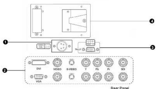
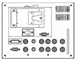
① Power Input
Connect the 12VDC input to the 4-Pin XLR power input connector. Power can be supplied from the included power supply, or from a variety of DC sources supplying at least 2 Amps at 12 Volts.
IMPORTANT: If using a power source other than the included power supply, be sure that the polarity of the DC input is correct:
Pin 1: GND
Pin 2: N/C Pin 3: N/C
Pin 4: +12VDC
② Signal Input/Output
Connections:
• Composite Video Input/Output (BNC)
• S-Video Input/Output (4-Pin Mini-DIN)
- YP_BP_H Input/Output (BNC x 3)
• SDI Input/Output (BNC)
• VGA (HD-15)
• DVI (29-Pin connector, DVI-D signals only)
All outputs are active and require the monitor to be powered.
3 Tally Interface
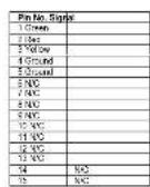
Each tally light is activated via the HD-15 connector by connecting the corresponding pin to ground. A variety of external devices can be used to perform the contact closure. No additional power should be supplied to the HD-15 port.
Tally Interface: HD-15 Pinout
4 V-Mount Battery Adapter
Accepts standard V-Mount 12V / 14.4V batteries
Compatible Input Formats
On-Screen Menu (continued)
| Format Composite S-Video YPsPr SDI VGA DVI-D | ||||||
| NTSC | ● | ● | ||||
| PAL | ● | ● | ||||
| 525i | ● ● ● | |||||
| 625i | ● ● ● | |||||
| 486p / 59.94 | ● | ● | ||||
| 576p / 50 | ● | ● | ||||
| 1035i / 60 | ● | ● | ||||
| 1035i / 59.94 | ● | ● | ||||
| 1080i / 60 | ● ● ● ● | |||||
| 1080i / 59.95 | ● ● ● ● | |||||
| 1080i / 50 | ● ● ● ● | |||||
| 1080psF / 24 | ● ● ● ● | |||||
| 1080psF / 23.98 | ● ● ● | |||||
| 1080p / 30 | ● | ● | ||||
| 1080p / 29.97 | ||||||
| 1080p / 25 | ||||||
| 720p / 60 | ● ● ● ● | |||||
| 720p / 59.94 | ● ● ● ● | |||||
| 720p / 50 | ● ● ● ● | |||||
| 720p / 30 | ● | ● | ||||
| 720p / 29.97 | ||||||
| 720p / 25 | ||||||
| 640 x 480 @ 60Hz | ● | ● | ||||
| 640 x 480 @ 75Hz | ● | ● | ||||
| 640 x 480 @ 85Hz | ● | ● | ||||
| 800 x 800 @ 60Hz | ● | ● | ||||
| 800 x 800 @ 75Hz | ● | ● | ||||
| 800 x 800 @ 85Hz | ● | |||||
| 1024 x 768 @ 60Hz | ● | ● | ||||
| 1024 x 768 @ 75Hz | ● | ● | ||||
| 1024 x 768 @ 85Hz | ● | ● | ||||
| 1280 x 1024 @ 60Hz | ● | ● | ||||
VIDEO CONFIGURATION SUBMENU (continued)
■ Monochrome Mode
Use this setting to enable monochrome mode. Only the luminance of the image will be displayed as a grayscale picture.
■ Blue-Only Mode
Use this setting to enable Blue-Only mode. This mode displays only the blue color component of the image, switching off the red and green components. Use this mode when calibrating the monitor to SMPTE color bars with the following procedure:
- Allow the monitor to warm up for at least 5-10 minutes.
- Display SMPTE split-field color bars on the monitor using the internal generator or an external source.
- Enable Monochrome mode.
- Locate the pluge pattern (super black, black, and gray bars) at the lower-right corner of the screen. Adjust the Brightness knob until there is no visible difference between the super black and black bars, but the gray bar is still visible.
- Adjust the Contrast knob until an even grayscale appears along the top bars.
- Disable Monochrome mode.
- Enstle Blue-Only mode and adjust the Color knob so that the outermost bars (white and blue) appear to match in brightness.
- Compostel/S-Video NTSC only: Adjust the Tint knob until the third bar from the left (cyan) and the third bar from the right (magenta) appear to match in brightness.
- Disable Blue-Only mode.
This mode bypasses the monitor's internal scaling function and displays incoming images in their native resolution and aspect ratio, with a one-to-one mapping:
- For incoming formats smaller than the native resolution of the LCD panel (1024 x 768), the image will be displayed in the center of the screen using only the necessary LCD pixels. For example, NTSC or PAL images will occupy exactly 720 x 486 or 720 x 576 pixels respectively. The surrounding pixels will be black.
- For incoming formats exceeding 1024 x 768 pixels, only the center 1024 x 768 of the incoming image will displayed occupying the whole screen, with the remainder of the picture cropped. For example, 1080Ip formats will both be cropped to 1024 x 768 and displayed full-screen.
Note: Pixel-to-Pixel™ mode will utilize the entire screen (1024 x 768) regardless of the aspect ratio setting. Pixel-to-Pixel™ mode is not available when using the VGA or DVI inputs.
On-Screen Menu (continued)
Use this setting to choose one of three color temperature presets:
• D55 (5500K)
• D65 (6500K)
• D93 (9300K)
• USER (Adjustable Color Bias and Gain)
■ Adjusting Color Bias
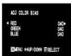
Color Bias Menu
Use this submenu to adjust bias of the color response. Adjust the bias for each color to alter the white balance of the image. The Color Temperature preset will automatically switch to USER when Color Bias settings are adjusted. It is normal for color bias adjustments to be very subtle.
■ Adjusting Color Gain
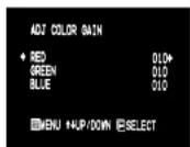
Color Gain Menu
Use this submenu to adjust gain of the color response. The Color Temperature preset will automatically switch to USER when Color Gain settings are adjusted.
On-Screen Menu
STRUCTURE OVERVIEW
| MAIN | MARKER SETUP | MARKER 16:9 | OFF, 129, 143, 43, 2851, 1,851, 92%, 93%, 90%, 88%, 90% |
| MARKER 4:3 | OFF, 95%, 93%, 90%, 88%, 80% | ||
| MARKER BACKGROUND | OFF, HALF, BLACK | ||
| CENTER MARKER | OFF, ON | ||
| VIDEO CONFIG | COLOR TEMP | DSS, DSS, D93, USFR | |
| ADJ COLOR BIAS | RED (0-100) | ||
| GREEN (0-100) | |||
| BLUE (0-100) | |||
| ADJ COLOR GAIN | RED (0-100) | ||
| GREEN (0-100) | |||
| BLUE (0-100) | |||
| MONO | OFF, ON | ||
| BLUE ONLY | OFF, ON | ||
| PIXEL TO PIXEL | OFF, ON | ||
| ASPECT RATIO | 4:3, 16:9 | ||
| SCAN | NORMAL, UNDER | ||
| DELAY | OFF, HV, V, H | ||
| SYSTEM CONFIG | SMPTE BAR | OFF, ON | |
| FUNCTION 1 | DELAY, RATIC, BACK, CENTER, MARKER, MONO, CTEMP, PTP | ||
| FUNCTION 2 | DELAY, RATIC, BACK, CENTER, MARKER, MONO, CTEMP, PTP | ||
| STATUS DISPLAY | OFF, ON | ||
| LOAD CONFIG | USR1, USR2, USR3, USR4, USRS, USRE, MFO | ||
| SAVE CONFIG | USR1, USR2, USR3, USR4, USRS, USRE |
MAIN MENU AND NAVIGATION
Access the main menu by pushing and holding the MENU button on the front panel of the monitor.
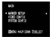
Main Menu
- Step through menu items using the ↑ and ↓ buttons.
- Choose a menu item by pressing SELECT
- Rotate through options using the ↑ and ↓ buttons.
- Choose a selling by pressing SELECT.
- Return to the previous menu by pressing MENU.
- Exit the main menu by pressing MENU. The menu will automatically time out after 8 seconds. After exiting the menu, wait 1-2 seconds before displaying the menu again.
On-Screen Menu (continued)
On-Screen Menu (continued)
MARKER SETUP SUBMENU
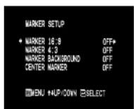
■ 16:9 Markers
Use this setting to superimpose one of 10 markers on the screen when in 16:9 mode. This setting is disabled when the aspect ratio is set to 4:3, or when Pixel-to-Pixel ^™ . Underscan, or H/V Delay is enabled.
- OFF (No Marker)
• 13:9 Aspect Ratio
• 14:9 Aspect Ratio
• 4:3 Aspect Ratio
• 2.35:1 Aspect Ratio
• 1.85:1 Aspect Ratio • 95% Safe Area - 93% Safe Area
- 90% Safe Area
• 88% Safe Area
• 80% Safe Area
16:9 Marker Examples:
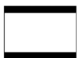
OFF (No Marker)
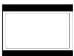
90% Safe Area
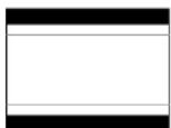
2.35:1 Aspect Ratio
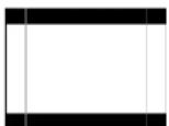
4:3 Aspect Ratio Marker
MARKER SETUP SUBMENU (continued)
■ 4:3 Markers
Use this setting to superimpose one of 5 markers on the screen when in 4:3 mode. This setting is disabled when aspect ratio is set to 16:9, or when Pixel-to-Pixel ^™ . Underscan, or HIV Delay is enabled.
- OFF (No Marker)
• 95% Safe Area
• 93% Safe Area - 90% Safe Area
• 88% Safe Area
• 60% Safe Area
4:3 Marker Examples:
OFF (No Marker)
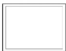
90% Sale Area
Marker Background
Use this setting to choose how selected markers are displayed on the screen:
- OFF The marker is superimposed on the complete image.
- Half-tone Image area beyond the marker is shown at 50% intensity.
- Black Image area beyond the marker is shown at 0% intensity (black).
Example (80% Marker in 4:3 Mode):
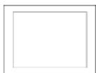
Background OFF
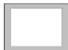
Half-lone Background
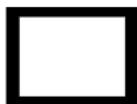
Black Background
■ Center Marker
Use this selling to display a center marker on the screen. This feature is not available when H/V delay is on.
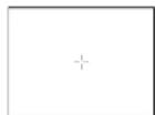
Center Marker

- Marshall Electronics
- Operating Instructions
- Warranty
- Optional Accessories
- ■ Batteries
- ■ Battery Chargers
- ■ Battery Adapters
- ■ Power Adapter Cables
- ■ Stands, Adapters, and Mounts
- ■ Sun Hoods
- ■ Cleaning Accessories
- Contents
- Product Overview
- Specifications (continued)
- Features
- Maintenance
- Specifications
- ■ PANEL
- S-Video (Y/C) Input / Output
- YP_RP_R Input / Output
- HD-SDI Input / Output
- VGA Input
- DVI Input
- ■ CONNECTORS
- Video Input
- Video Output (Active Loop-Through)
- Power Input
- Tally Interface
- ■ TALLY
- ELECTRICAL
- MECHANICAL
- Installation and Initial Setup
- ■ Unpacking
- ■ Installation
- ■ Connections and Power-On
- Front Panel Features
- ① Power Button
- ② Input Select Buttons
- On-Screen Menu Navigation Buttons
- User-Definable Function Buttons
- ⑤ Image Adjustment Knobs
- On-Screen Menu (continued)
- ■ User-Definable Function Buttons
- ■ Status Display
- ■ Saving and Loading User Configuration Presets
- VIDEO CONFIGURATION SUBMENU (continued)
- ■ Aspect Ratio Settings
- ■ Scanning Modes
- ■ Delay Modes
- Rear Panel Features
- ① Power Input
- ② Signal Input/Output
- Tally Interface
- V-Mount Battery Adapter
- ■ Monochrome Mode
- ■ Blue-Only Mode
- ■ Adjusting Color Bias
- ■ Adjusting Color Gain
- On-Screen Menu
- STRUCTURE OVERVIEW
- MAIN MENU AND NAVIGATION
- MARKER SETUP SUBMENU
- ■ 16:9 Markers
- 16:9 Marker Examples:
- MARKER SETUP SUBMENU (continued)
- ■ 4:3 Markers
- 4:3 Marker Examples:
- Marker Background
- Example (80% Marker in 4:3 Mode):
- ■ Center Marker
Brand : Marshall Electronics
Model : V-R841DP-AFHD
Category : Monitor