Zoe CF1136 - Uncategorized Crosley - Free user manual and instructions
Find the device manual for free Zoe CF1136 Crosley in PDF.


| Product Type | Cabinet / Console Table |
| Brand | Crosley |
| Model | Zoe CF1136 |
| Assembly Required | Yes |
| Material | Engineered Wood |
| Number of Parts | 12 Panels + Hardware |
| Included Hardware | Cam Locks, Cam Bolts, Wood Dowels, Screws, Bolts, Adjustable Levelers, Metal Plates, Binding Posts, Covers |
| Tools Required | Phillips Head Screwdriver, Allen Wrenches (included) |
| Assembly Instructions | Step-by-step manual included; do not use power tools |
| Special Features | Adjustable levelers for uneven floors; cam lock system for secure assembly |
| Extra Hardware | Extra cam bolts, wood dowels, screws provided |
| Estimated Assembly Time | 1-2 hours |
| Care Instructions | Clean with dry cloth; avoid moisture; do not use abrasive cleaners |
Frequently Asked Questions - Zoe CF1136 Crosley
User questions about Zoe CF1136 Crosley
0 question about this device. Answer the ones you know or ask your own.
Ask a new question about this device
Download the instructions for your Uncategorized in PDF format for free! Find your manual Zoe CF1136 - Crosley and take your electronic device back in hand. On this page are published all the documents necessary for the use of your device. Zoe CF1136 by Crosley.
USER MANUAL Zoe CF1136 Crosley
natural_image
Isometric line drawing of a rectangular box with four corner supports (no text or symbols)PART LIST
A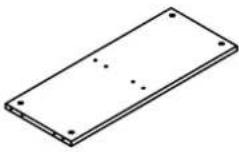 | B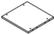 | C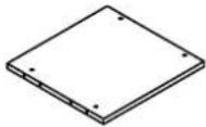 | D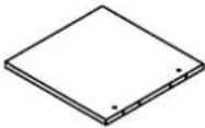 | E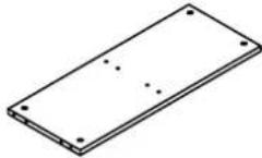 |
| Top Panel1 PC | Right Panel1 PC | Left Panel1 PC | Partition Panel1 PC | Bottom Panel1 PC |
F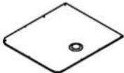 | G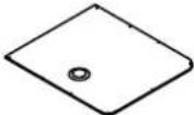 | H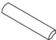 | I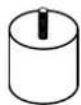 | J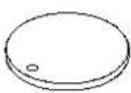 |
| Left Back Panel1 PC | Right Back Panel1 PC | Corner4 PCS | Leg4 PCS | Cover2 PCS |
HARDWARE LIST
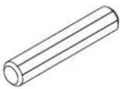 ∅10*50mm ∅10*50mm | 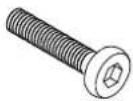 1-1/2"*∅1/4 1/2"*∅1/4 1-1/2"*∅1/4 1/2"*∅1/4 | 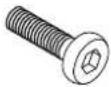 | 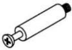 | #5#4#3#2#1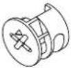 | |||
| Wood Dowel20 PCS (Extra 1) | Long Bolt2 PCS (Extra 1) | Short Bolt4 PCS (Extra 1) | Cam Bolt18 PCS (Extra 1) | Cam Lock18 PCS (Extra 1) | |||
| #6 | #7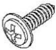 | 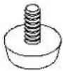 | #8 | #9 #10 | 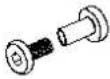 | 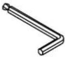 ∅M4 ∅M4 | |
| Screw20 PCS (Extra 1) | Adjustable Leveler4 PCS | Cover10 PCS | Binding Post2 SETS (Extra 1) | Allen Wrench1 PC | |||
#11 ∅M2 ∅M2 | #12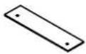 | ||||||
| Small Allen Wrench1 PC | Metal Plate2 PCS | ||||||
ADDITIONAL TOOLS (Not Provided)
Note: It is not recommended to use power tools during assembly.
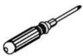
Phillips Head Screwdriver
Note: Wood dowels are intended for alignment. Additional clearance between wood dowel and pre-drilled hole is intentional for ease of assembly.
Step 1. Insert cam bolts (part #4) into pre-drilled holes of top panel and corners (parts A & H) using phillips head screwdriver.
Note : Do not over tighten cam bolts. Stop tightening once threads on cam bolts are no longer visible.
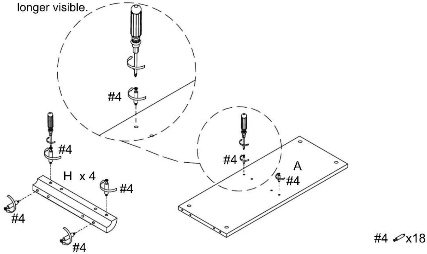
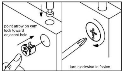
Step 2. Attach corners (part H) to panels (parts A & E) using wood dowels (part #1), cam locks (part #5) and phillips head screwdriver.
Note : Cam locks must rotate a full 180°. See pictured insert.
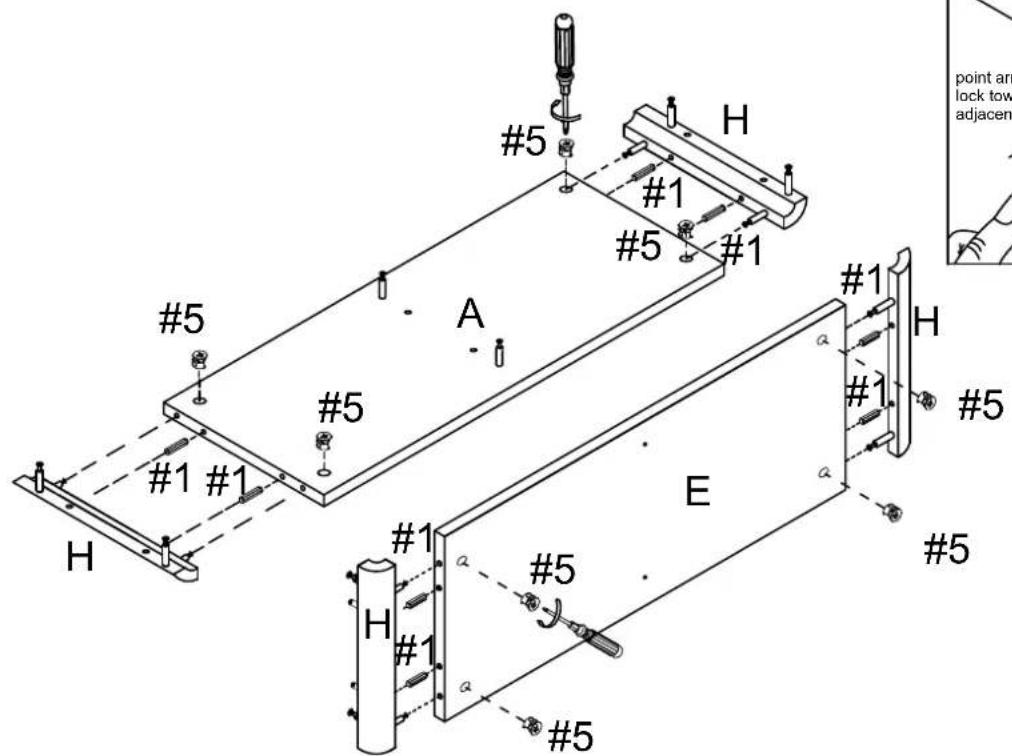
1 ♡ x 8
5 × 8
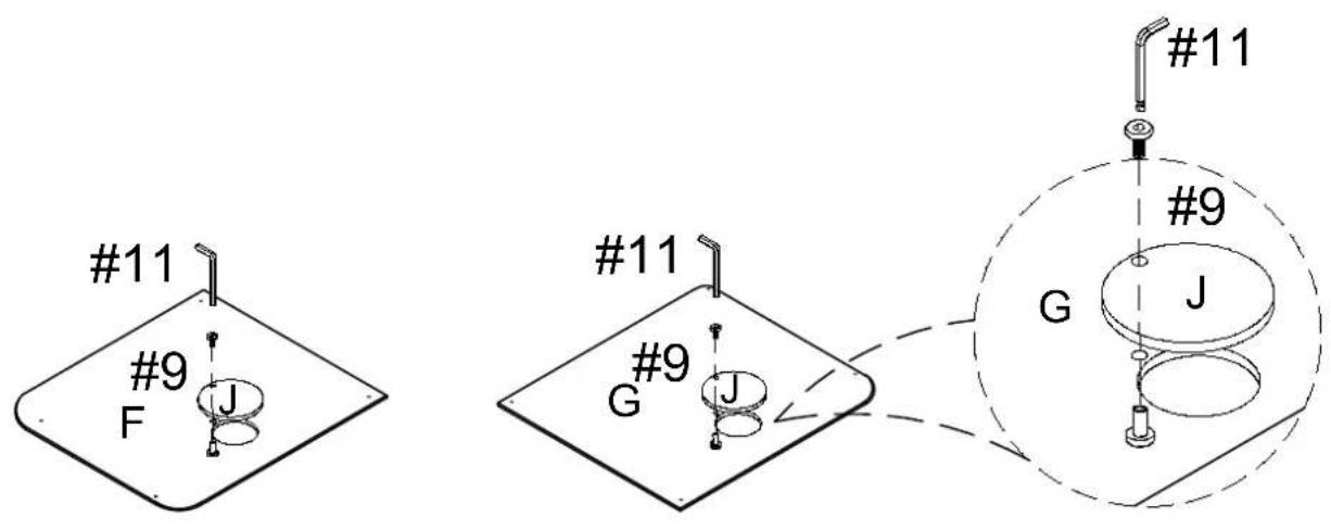
Step 3. Attach covers (part J) to back panels (parts F & G) using binding posts (part #9) and small allen wrench (part #11).
9 x 2
11 \ x 1
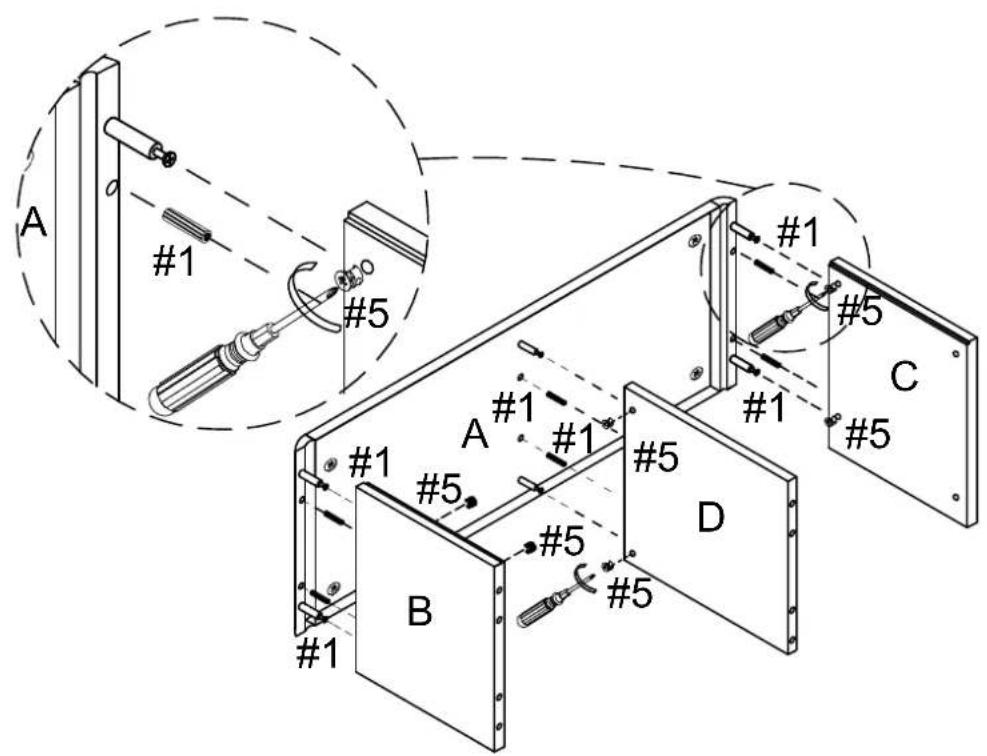
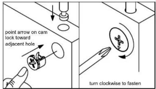
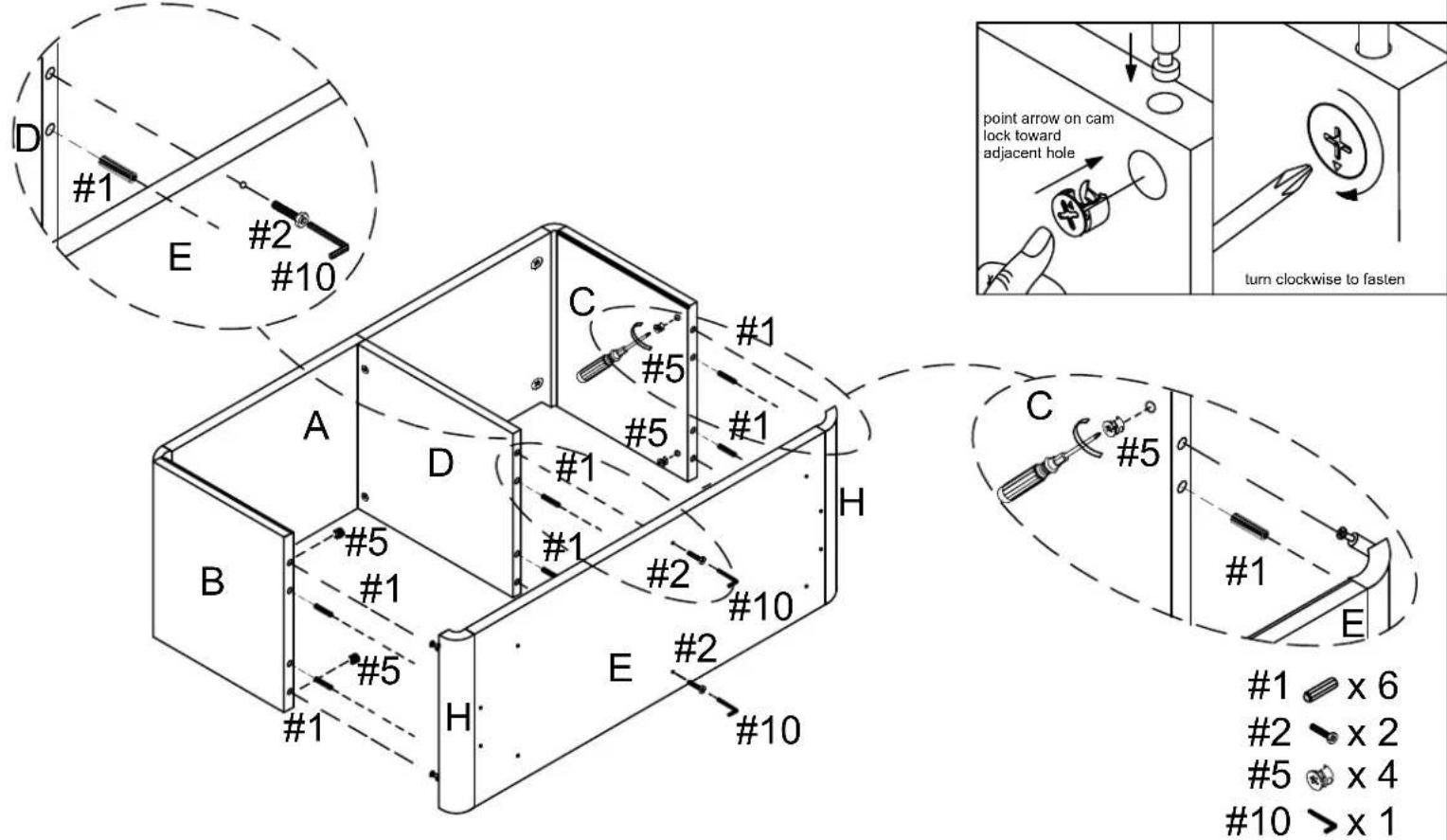
Step 4 . Attach panels (parts B, C & D) to top panel (part A) using wood dowels (part #1), cam locks (part #5) and phillips head screwdriver.
Note : Cam locks must rotate a full 180°. See pictured insert.
1 ≡ x 6
5 × 6
Step 5. Attach panels (parts E & H) to assembled unit (parts B, C & D) using wood dowels (part #1), cam locks (part #5), long bolts (part #2), allen wrench (part #10) and phillips head screwdriver.
Note : Cam locks must rotate a full 180°. See pictured insert.
Step 6. Attach metal plates (part #12) to bottom panel (part E) using short bolts (part #3) and allen wrench (part #10). Attach legs (part I) to bottom panel (part E). Attach adjustable levelers (part #7) to legs (part I).
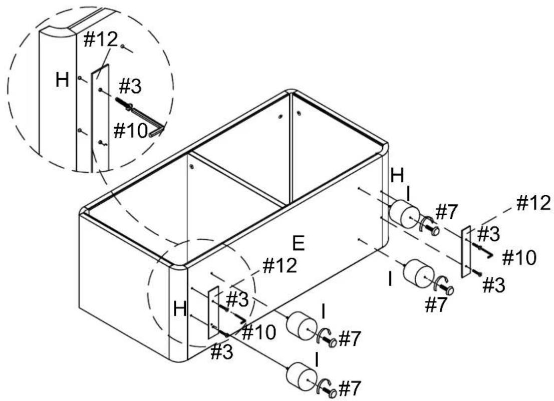
3×4
7 ♘ x 4
10> x 1
12×2
Step 7. Attach back panels (parts F & G) to assembled unit (parts A, B, C, D & E) using screws (part #6) and phillips head screwdriver.
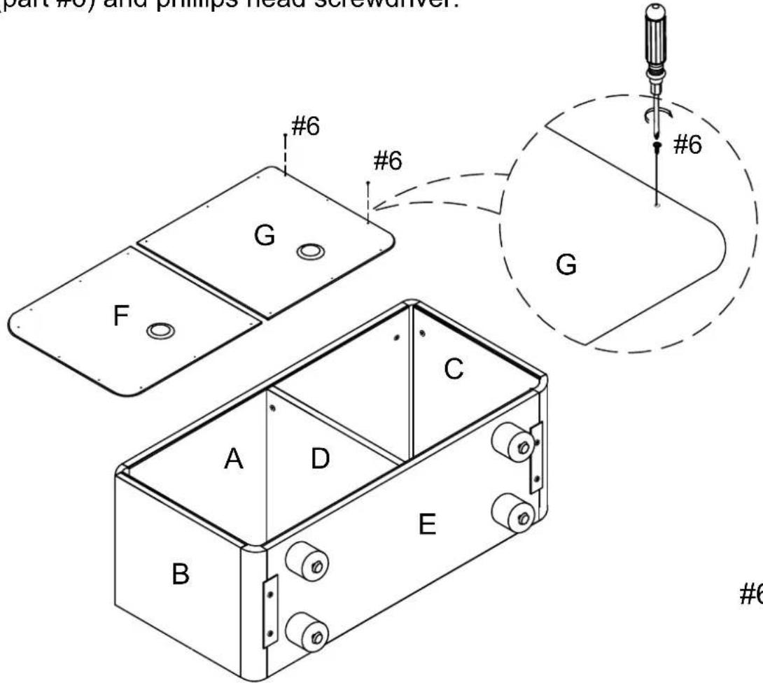
6 × 20
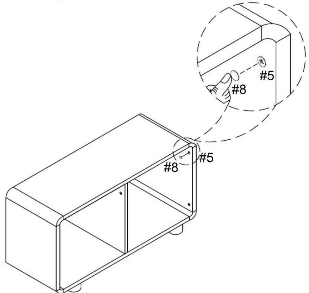
Step 8. Attach covers (part #8) to the hole of cam locks (part #5).