USER MANUAL UN0815 Scotsman
User and Installation Manual for Models
UN0815A-1A and UF0915A-1A
UN1215A-1A and UF1415A-1A
UN1520A-1A and UF2020A-1A
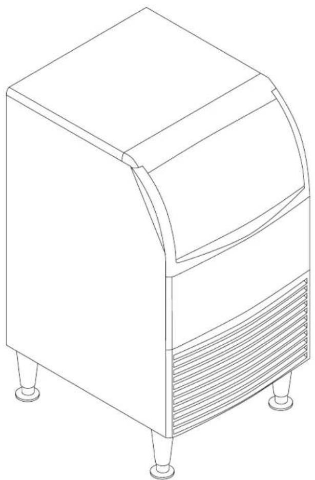
natural_image
Line drawing of a four-legged appliance with a curved top and side panel (no text or symbols)
UF0915, 1415, 2020 and UN0815, 1215, 1520 User Manual
Introduction
The design of this product is the result of years of experience in developing commercial ice machines. It has been designed for simple operation in a wide range of locations. Please follow the instructions for installation and maintenance to get the most use from this ice machine.
Table of Contents
Important Details 3
Pre-Installation 4
Unpacking and Setup 5
Cabinet Layout, UN0815, UN1215, UF0915, UF1415 .... 6
Back View, UN0815, UN1215, UF0915, UF1415 .... 7
Cabinet Layout, UN1520, UF2020 8
Back View, UN1520, UF2020 9
Component Location 10
Connect the Water Supply 11
Connect the Power 12
Initial Start Up 13
Use and Operational Notes ...... 14
Maintenance: Cleaning The Water System 15
Cleaning the Condenser 17
Before Calling For Service 18
Wiring Diagram 19
Observe the Caution and Warning notices. They are indicators of important safety information. Keep this manual for future reference.

WARNING: Cancer and Reproductive Harm www.P65Warnings.ca.gov
Important Details
The machine is designed for use indoors in a controlled environment. It must be kept dry, not overheated or subjected to excessive cold. The water and power supply must be maintained or the machine will stop making ice.
There are limits to how hot or cold the room it's in can be.
• Minimum air temperature: 50 °F or 10°C
• Maximum air temperature: 100 °F or 38°C
There are limits to the voltage supply to the unit, voltages vary by model:
Voltage
- Minimum 104
• Maximum 126
Water
Temperature
• Minimum water temperature: 40 °F or 4.5°C
• Maximum water temperature: 100 °F or 38°C.
Quality
- Water supply must be potable by the localities definition.
Water Pressure
• Maximum pressure. static: 80 psi or 5.5 bar
• Minimum pressure, dynamic: 15 psi or 1 bar
Water Conductivity
- The water supply must have a conductivity of at least 10 microSiemens/cm.
A drain will be needed for melted ice and rinse water
Warranty:
The warranty statement for this product is provided separately from this manual. Refer to it for applicable coverage. In general warranty covers defects in material or workmanship. It does not cover maintenance, corrections to installations, or situations when the machine is operated in circumstances that exceed the limitations printed above.
This is a commercial model, if installed in a residence some commercial service companies may not be able to service it on site.
The manufacturer has designed and produced this machine with the finest in materials. The manufacturer assumes no liability for units that have been altered in any way. Alterations or part substitutions will void the warranty. Specifications and designs are subject to change without notice.
Options:
There are two floor mounting kits available:
• KUFM15: for 15" models
- KUFM20: for 20" model
UF0915, 1415, 2020 and UN0815, 1215, 1520 User Manual
Pre-Installation
This appliance is intended to be used in commercial applications including:
- Restaurant kitchens
- Bars
- Hotels
Dimensions and Electrical:
| Model Electrical | (volts/Hz/Phase) | Ice Form Width(in / cm) | Depth(in/cm) | Height (w/o legs)(in/cm) | Power Cord |
| UN0815A-1A 115/60 | /1 Nugget 15 / 38 23 | 7 / 60.3 31.94 / 81.1 5-15P | | | |
| UN1215A-1A 115/60 | /1 Nugget 15 / 38 23 | 7 / 60.3 31.94 / 81.1 same | | | |
| UN1520A-1A 115/60 | /1 Nugget 20 / 51 23 | 7 / 60.3 31.94 / 81.1 same | | | |
| UF0915A-1A 115/60 | /1 Flake 15 / 38 23.7 | / 60.3 31.94 / 81.1 same | | | |
| UF1415A-1A 115/60 | /1 Flake 15 / 38 23.7 | / 60.3 31.94 / 81.1 same | | | |
| UF2020A-1A 115/60 | /1 Flake 20 / 51 23.7 | / 60.3 31.94 / 81.1 same | | | |
Location:
The unit can be built into a cabinet as the air flow is in and out the front. The front of the machine must not be blocked. Certain maintenance or repair procedures will require removal of the top, back and side panels, so plan ahead for service and maintenance needs.
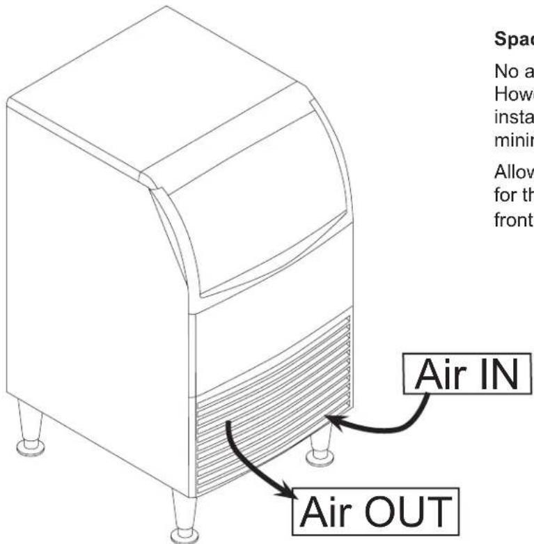
Spacing:
No additional spacing is required at the top or sides. However, suggested minimum side clearance for installation is 1/8 inch or 3 mm and suggested minimum top clearance is 1/4 inch or 7 mm.
Allow 4 inches (100 mm) minimum space at the back for the utility connections. Do not block louvers at the front of the cabinet.
Unpacking and Setup
Remove all shipping and packing materials that may be in the ice storage bin.
The unit can be installed with or without legs. The cabinet is equipped with small bumpers on the base to allow placement without legs.
An optional floor mounting kit is also available to fill the gap between the machine and floor if not using legs.
If using legs, carefully tip the machine and install the legs by screwing them into the leg sockets in the bottom of the machine. For reference, the thread size is 5/8 - 11.
If the machine has been tipped onto its side or back allow 1 hour before starting the unit for the oil in the refrigeration system to return to the compressor.
Place the machine in its intended location and level it front to back and left to right. If using legs, adjust their feet in and out to level the cabinet.
If legs are not used the bottom edges of the cabinet must be sealed to the floor to pass most codes.
If built into a cabinet, the adjacent cabinet walls will provide the means for containment. There are no means for attachment to the cabinet.
Be sure to remove the plastic covering the exterior panels, if left on it will be much harder to remove later.
Location of Dataplate
Model and Serial plate with
QR code located behind
front panel.
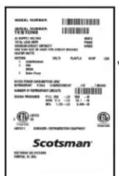
Model and Serial Number Dataplate
October 2019

![POWER CORD POTABLE WATER INLET 1/4" OD. PLASTIC TUBING (5ft) [ 15.8cm ] 6.2in [ 3.7cm ] 1.5in [ 8cm ] [ 19.1cm ] 7.5in DRAIN 3/4" FPT](/content/2026/05/944220/images/bcb8d34a726ebe7a3ca38611b26f86f30740caa9f6a1520cf4893b122327205b.jpg)
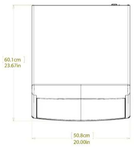
![95.4cm 37.56in 81.1cm 31.94in AIR OUTLET AIR INLET [42.5cm] 16.75in](/content/2026/05/944220/images/4282bbd0011f1087ff16162d451697dc59b7f7a1ed1901f8af282da1e745e395.jpg)
![68.9cm 27.13in [15.2cm] 6.00in [48.3cm] 19.00in [10.2cm] 4.00in MINIMUM UTILITY CLEARENCE](/content/2026/05/944220/images/1c1616b1d9ea720f6837c348ca342439639e768fc51b661161c74a04680fe183.jpg)
![POWER CORD POTABLE WATER INLET 1/4" OD. PLASTIC TUBING (5ft) [15.8cm] 6.21in [3.7cm] 1.46in [8cm] 3.17in [32cm] 12.61in DRAIN 3/4" FPT [7cm] 2.75in](/content/2026/05/944220/images/62aa53052c3c29208ba664eb315ef4cf3a0d3660de588ede59156cbbc3dc72fb.jpg)
UF0915, 1415, 2020 and UN0815, 1215, 1520 User Manual
Component Location
All models are essentially automatic and require very little contact other than routine cleaning.
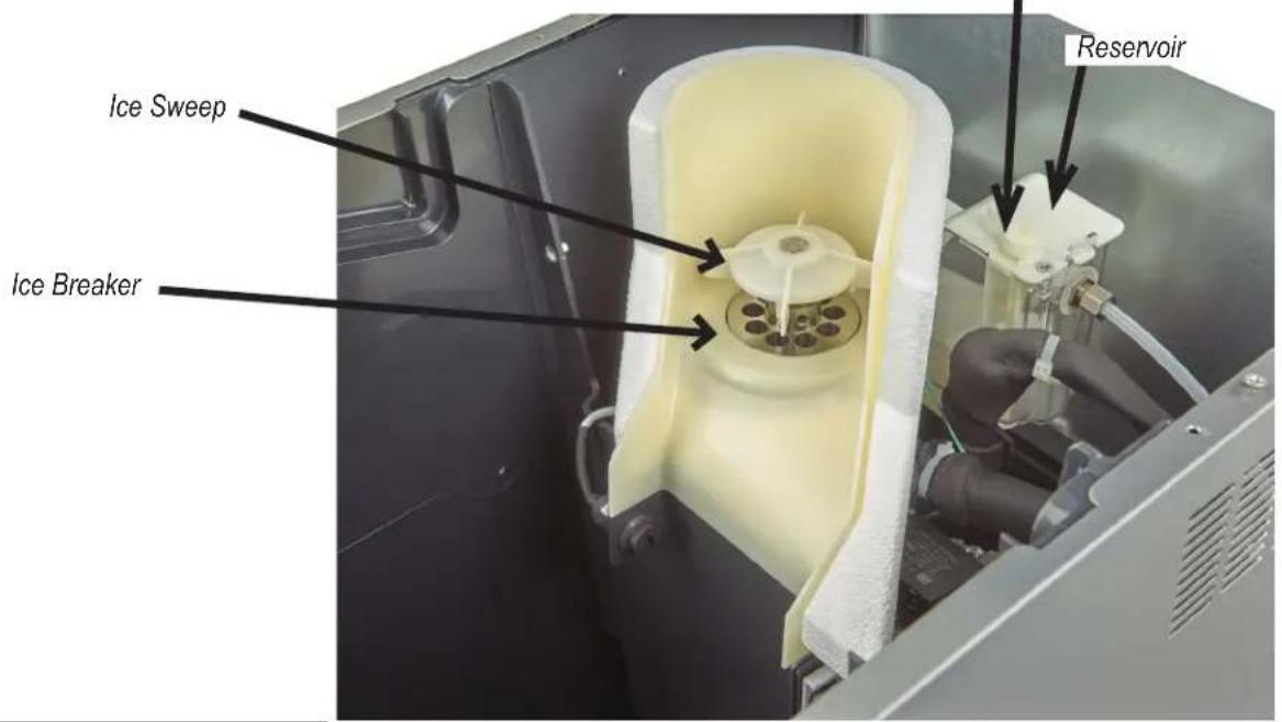
The cleaning process does require understanding of certain components. They include the on and off buttons, condenser fins, water reservoir and ice breaker.
Float Valve Lever
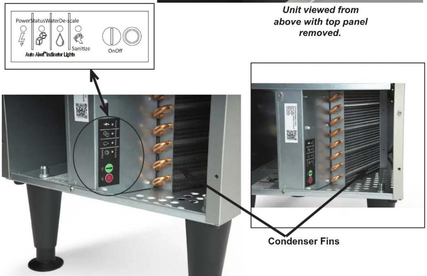
Front Panel Removed. On and Off Buttons and Indicator Lights
October 2019
Connect the Water Supply
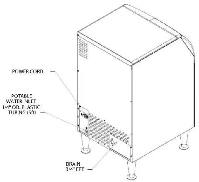
- The water supply connection is at the back panel. It is a 5' (1.5 meter) 1/4 inch (6.35 mm) OD plastic tube.
- A hand actuated valve within site of the machine is required to isolate the unit when it's being serviced.
- The machine has a built-in back flow preventer (an air gap between the water's entry point and the top of the reservoir water), no additional back flow preventer is needed.
• Water flow rate into machine is .125 gal/min
Units that are built into a cabinet:
Include a loop or coil of tubing between the water supply and the connection on the ice machine. When the machine is pushed back into the cabinet the tubing will coil and not kink.
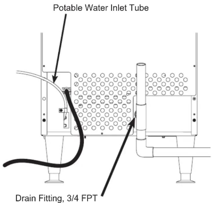
Important: connect to potable water supply only. Open the hand water valve to flush water through the connection point before connecting to the ice machine.
- Cut cable ties securing hose and power cord to unit.
- Connect to cold, potable water using the necessary adapters for the 1/4 inch OD plastic tube.
- If using compression fittings they require a ferrule or sleeve and insert.
- A female 3/8 compression adapter x 1/4 OD compression allows connection to a typical 3/8 OD compression angle valve.
- Another connection method is by quick connect fittings.
Note: Do not use a piercing-type saddle valve to connect to the building's water supply. Valves of that type restrict water flow and clog easily.
Connect the drain
The drain connection is at the back panel. The fitting size is 34 FPT. And it is plastic. Do not overheat.
- Drain tube material must be rigid and meet local code.
- Traps in the bin drain line without vents ahead of them will cause poor draining
-
The drain must be vented if there is a long horizontal run 5 feet or more. All drains are gravity and must have a minimum fall of 1/4'' per foot of horizontal run.
-
Connect rigid tubing to this fitting and vent it at the machine, use an 8 inch or 200 mm vertical tube for the vent.
- Slope drain tubing down from the ice machine to the building drain and the slope must be at least 14 inch per foot or 20 mm per meter.
- Insulate the drain tubing to reduce condensation and is recommended for environments that have high humidity.
Due to the potential for leaks, condensate pumps are not recommended.
Connect the Power
This is a cord-connected unit, and must be connected to its own dedicated power supply. Check the dataplate on the back of the machine to confirm the voltage and per the dataplate use fuses or HACR circuit breakers.
Power Cord:
This 115 volt model is equipped with a cord and 5-15P plug.

Follow All Local Codes
- This Unit Must Be
Grounded. Do not use extension cords and do not disable or by-pass ground prong on electrical plug.
Plug the power cord into the proper power supply.
Note: Electrical outlets can become worn and the power supply can then be erratic. Have it replaced if the connection is loose.
After utility connections
- Level the cabinet, use the leg levelers on the end of the legs to adjust to cabinet height. Legs should have been installed when the unit was unpacked.
- Wash the bin and door. If desired, the interior of the bin could be sanitized.
- Locate the scoop, wash it and have it available for use when needed.
Installation check list
- Has the machine been installed indoors in an environment suitable for it?
- Have all of the shipping items and packaging been removed?
- Has the plastic covering the exterior panels been removed?
- Has the water supply been connected and confirmed to not leak?
- Has a properly sized and sloped drain tube been attached?
- Has the correct voltage power supply been connected?
UF0915, 1415, 2020 and UN0815, 1215, 1520 User Manual
Initial Start Up
- Remove the front panel by removing the two screws holding it to the cabinet and pulling the panel down and off the machine.
- Turn on the water supply, correct any leaks.
- Locate the On push button.

- Confirm that the Power indicator light is on and that the Water indicator light is off.
If the Water indicator light is blinking red, the unit will not start as there is no water sensed and ice cannot be made. Correct any condition keeping water from filling the reservoir.
- Push and release the On button.
- The Status indicator light will be on. Warm air will begin to blow out the left front of the machine and the auger drive motor will switch on. Within a minute or so the ice will fall down and slide into the ice storage bin. It is normal for a small amount of water to also drip from the ice making area.
- Check for any unusual noises, such as fan motor vibration and correct as needed.
- Return the front panel to its normal position.
UF0915, 1415, 2020 and UN0815, 1215, 1520 User Manual
Use and Operational Notes
To use, simply lift the door by its bottom edge and slide it up and into the top of the machine. Use the scoop to remove ice and close the door.
The machine will make the most ice if it has plenty of room to breathe. This is an air cooled product and it must be able to take in room air and discharge air heated by the ice making process.
Blockage of vents or exposure to excessive heat will reduce the ice making and storage capacity.
The storage bin is insulated but not refrigerated, so ice will melt during use. That is normal and assures that fresh ice is available in the bin.
The fan will make some noise during operation, however rattles and other vibrations are not normal and should be attended to.
If the machine is in a space colder than the minimums listed it can become damaged.
Caution: The cabinet is not designed to support anything placed on it. Do NOT step or stand on it.
On and Off
The On and Off buttons are located behind the louvered front panel. Remove that panel to access those buttons.
To Shut Off: Push and release the Off button and the unit will begin a shut down. Push and hold the Off button for an immediate shut off.
Status Indicator Light
Glows green when either making ice or when the bin is full of ice (optical sensors blocked by ice).
Clean Indicator Light
Serves as a reminder that it is time to have the unit cleaned. Normally off. This light glows after 6 months of power up time between cleanings. It will go out after the unit has been cleaned using the process in this manual and / or the one on the ice machine's cleaning label.
Water Indicator Light
Normally off. It glows when there is power to the unit but no water sensed in the reservoir. A lack of water will trigger a unit shut down. The unit will automatically restart after water has been restored.

UF0915, 1415, 2020 and UN0815, 1215, 1520 User Manual
Maintenance: Cleaning The Water System
Frequency: Recommended about twice a year. Units that are used heavily or are on highly mineralized water may require more frequent cleaning.
Cleaning this machine involves adding a solution of scale remover and water to the ice machine and continuing to add it as it makes ice. The scale remover must be diluted to the correct ratio. This is followed by sanitizing. The ice machine must be connected to power, water and drain during this process. Recommended tools:
Rubber gloves, small scrub brush & scale remover.
- Remove the top panel for reservoir access.
Note: If the unit must be pulled out to remove the panel and access the water reservoir, be sure that the water supply, drain and power remain connected
- Remove the front panel for control access.
- Scoop out and discard all of the ice.
- Press and hold the Off button until the machine shuts off.
- Locate float valve on/off lever. Rotate to shut water supply OFF.
- Push tab on front edge of reservoir cover and remove the cover.
Note: Adjacent wires are low voltage and are not hazardous.
- Locate drain plug and pull the drain plug out to drain the reservoir and evaporator. When draining is complete, return the plug to its original position.
CAUTION

natural_image
Silhouette of a hand holding a test tube with a droplet emerging from the palm (no text or symbols)
Ice machine scale remover contains acids. Acids can cause burns.
If concentrated cleaner comes in contact with skin, flush with water. If swallowed, do NOT induce vomiting. Give large amounts of water or milk. Call Physician immediately. Keep out of the reach of children.
- Mix a solution of Clear 1 scale remover with water: 2.5 ounces of Clear 1 with 1 quart (32 oz) of warm (90°F/32°C to 110°F/43°C) potable water.
Note: Take care not to spill any scale remover on any nearby surface. Immediately wipe any spill with baking soda and water.
- Fill the reservoir with the scale remover solution. That will be about 8 ounces.
- Unscrew (rotate CCW) and remove the ice sweep.
- Wash the ice sweep and lower part of the breaker with the scale remover solution. Remove as much scale as possible.
CAUTION
- Return the ice sweep to its original position.
- Press and HOLD the both the On and Off buttons for 5 seconds. The Time to Clean light will blink on and off.
The auger motor will be operating for 20 minutes, after that the compressor will start and in about 5-8 minutes the machine will start to make ice. The Time to Clean light will now glow steady until the clean cycle is complete.
CAUTION
Caution: Keep fingers away from moving parts.
October 2019
UF0915, 1415, 2020 and UN0815, 1215, 1520 User Manual
- After ice making starts, continuously add scale remover solution to the reservoir to keep it about half full.
- When all remaining solution is used, rotate the float valve lever to the ON position. Ice will continue to be made.
- After 40 minutes (20 of no ice making and 20 making ice) the ice machine and all the control panel lights will shut off.
- Rotate float valve lever to Off and pull the drain plug again to drain the system, then replace it.
- Pour a gallon of hot (95°F. - 115°F.) water into the bin to flush out the drain and melt all ice that was made during the cleaning process. Be sure all ice is melted.
- Mix another solution of 2.5 ounces of Clear 1 Scale Remover and 1 quart of 90^ / 32^ to 110^ / 43^ potable water and clean the bin liner of mineral scale by using the scale remover solution to scrub the scale off of the liner.
- Rinse the liner with hot water.
Sanitize Water System after scale removal to complete the Water System Cleaning process.
- Create a solution of sanitizer.
- Mix 4 oz/118ml of NuCalgon IMS and 2.5 gal/9.5L of (90°F/32°C to 110°F/43°C) potable water to create a 200 ppm solution.
- Rotate the reservoir's water shut off valve to shut the water supply OFF. If water reservoir cover has been placed on reservoir, remove it.
- Pour the sanitizing solution into the reservoir until it is full to but not over the overflow point (about 8 oz) and wait 2 minutes.
- Press the On button to turn the ice machine ON.
- Operate the machine for at least 15 minutes, adding sanitizer to the reservoir as needed to keep it at least half full, and then push and release the Off button to shut it OFF.
- Remove the ice sweep.
- Wash the reservoir cover, ice sweep, breaker and the inside of the ice chute with the sanitizer solution.
CAUTION
- Return the ice sweep to its normal position.
- Return the reservoir cover to its normal position.
- Drain the solution from the system by pulling the drain plug.
- Return plug when drained.
- Rinse bin liner with clean water. Be sure all ice has been melted.
- Use sanitizer mix on all bin surface areas and areas that may contact the ice.
- Rinse with clean water.
- Rotate water shut off valve to turn the water supply ON.
- Push and release the On button to restart ice making.
- Operate the machine for 15 minutes and then pour water onto the ice in the bin until it has all been melted.
- Return the top and front panels to their normal positions.
The ice scoop should be washed regularly, wash it just like any other food container
UF0915, 1415, 2020 and UN0815, 1215, 1520 User Manual
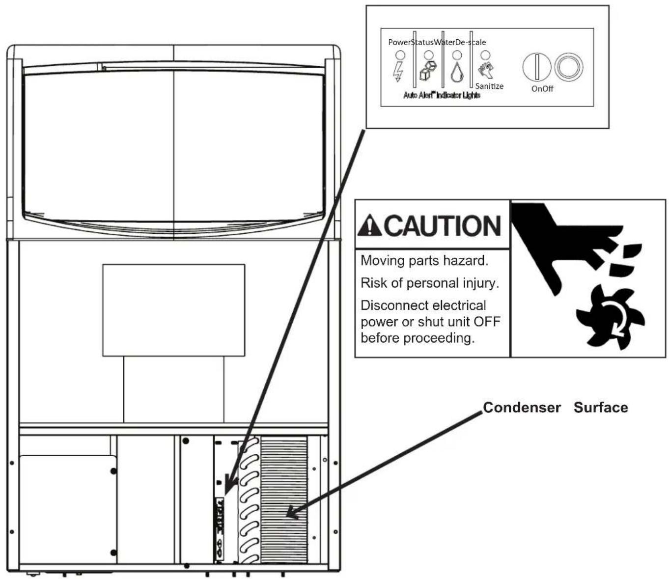
Cleaning the Condenser
- Remove the front panel.
- Push and hold the OFF button until the machine stops and / or the Status light is not glowing.
- Vacuum the surface of the condenser fins, carefully brush off any loose dirt. If grease is embedded use coil cleaner to wash it out.
- Push and release the On button.
- Return the front panel to its original position.
Other maintenance
Clean the optical sensors.
- Mix solution of 4 ounces of Clear 1 Ice Machine Scale Remover and 1.5qt/1.4L of 90°F/32°C to 110°F/43°C water.
- Remove sensors from inner cover by removing the white c-clip.
- Use cotton swab and cleaning solution to thoroughly clean photo sensors.
- Rinse sensors with clean water.
- Reinstall sensors in inner panel.
UF0915, 1415, 2020 and UN0815, 1215, 1520 User Manual
Other maintenance
Clean the optical sensors.
-
Mix solution of 4 ounces of Clear 1 Ice Machine Scale Remover and 1.5qt/1.4L of 90°F/32°C to 110°F/43°C water.
-
Remove chute cover from back of bin.

- Remove sensors from inner cover by removing the white c-clip.

- Use cotton swab and cleaning solution to thoroughly clean photo sensor lens
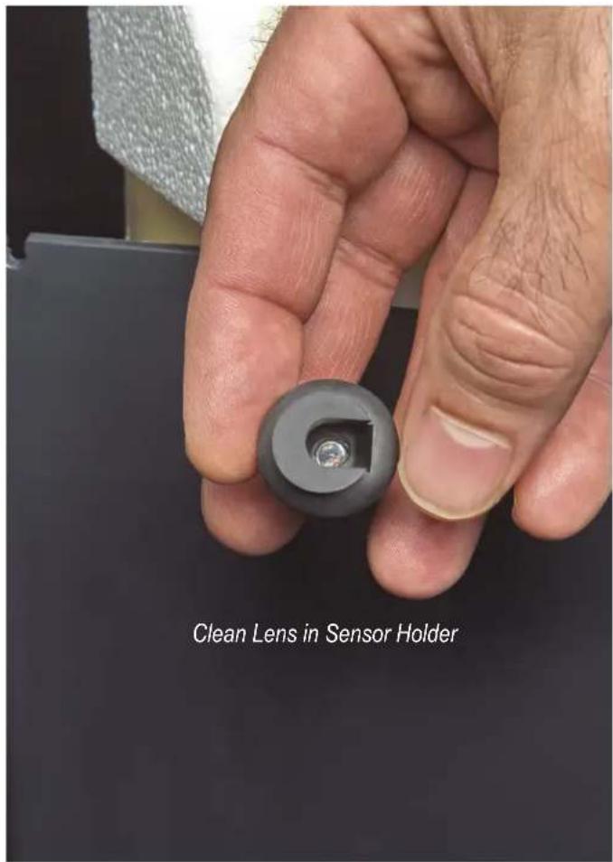
Note: Do not use sharp object to clean lens.
-
Rinse sensors with clean water.
-
Reinstall sensors in inner panel.
UF0915, 1415, 2020 and UN0815, 1215, 1520 User Manual
Before Calling For Service
No ice – check water supply. Restore water supply to unit if shut off. Remove front panel and check water indicator light, if ON, the unit is not sensing water.
Note: Unit will automatically restart when the water supply is restored.
Note: Unit will NOT operate if connected to an ultra pure water supply. Conductivity must be above the listed limit (see page 3).
No ice – check power supply. Remove front panel, if there are no lights on the control panel there is no power to the controller. Confirm unit is plugged into a working outlet of the correct voltage.
Note: Unit will automatically restart when power is restored.
No ice - check for false bin full caused by mineral scale on the optical sensors, located at the top of the ice chute. Status light green with no ice being made is a sign of false bin full.
Carefully clean the optical sensors of accumulated scale. Do not scrape with a sharp object.
Slow production – check condenser for dirt, clean condenser.
Slow production – check temperature of cabinet, if the room is hot or air flow restricted, production will be slow.
All four indicator lights are blinking:
Call for service.


CAUTION:
THIS UNIT MUST
BE GROUNDED
SCOTSMAN ICE SYSTEMS
101 Corporate Woods Parkway
Vernon Hills, IL 60061
USA
847-215-4500
www.scotsman-ice.com