SkyBox EXA - Machine à effets Blizzard Lighting - Free user manual and instructions
Find the device manual for free SkyBox EXA Blizzard Lighting in PDF.


| Product Type | LED PAR Fixture with RGBAW+UV 6-in-1 LEDs |
| Dimensions (W x D x H) | 6.5 x 5.12 x 6.5 in (165 x 130 x 165 mm) |
| Weight | 9.3 lbs (4.5 kg) |
| Power Supply | 100-264VAC, 47-63 Hz |
| Power Consumption | 84W, 0.54A |
| Light Source | 7x 15W 6-in-1 RGBAW+UV LEDs |
| LED Lifespan | 100,000 hours |
| Beam Angle | 25° optics (26° beam, 30° field) |
| Luminous Intensity | 10,300 Lux @ 1m, 2,850 Lux @ 2m |
| DMX Channels | 6, 7, 8, or 11 channels (selectable) |
| Control Protocol | USITT DMX-512 |
| Wireless DMX | Built-in AnyFi™ (Skywire™ or W-DMX™) |
| Battery Type | Intelion™ Lithium-Ion internal |
| Battery Life | Up to 20 hours (varies by mode) |
| Charging Time | 4 hours for full charge |
| Color Mixing | RGBAW+UV with manual, DMX, or preset control |
| Strobe | Variable speed (0-15) via DMX or control panel |
| Dimming | Electronic, 0-100% with selectable curves (Linear, Square Law, Inverse Square, S-curve) |
| Operating Modes | Standalone, Master/Slave, Sound Active, DMX, Auto Run |
| Mounting | Dual mounting brackets with locking knobs; safety cable required |
| Cooling | Variable-speed internal fan |
| Maximum Ambient Temperature | 104°F (40°C) |
| Safety | Indoor use only; do not expose to rain/moisture; use safety chain; avoid direct eye exposure |
| Warranty | 2-year limited (does not cover LED damage) |
Frequently Asked Questions - SkyBox EXA Blizzard Lighting
User questions about SkyBox EXA Blizzard Lighting
0 question about this device. Answer the ones you know or ask your own.
Ask a new question about this device
Download the instructions for your Machine à effets in PDF format for free! Find your manual SkyBox EXA - Blizzard Lighting and take your electronic device back in hand. On this page are published all the documents necessary for the use of your device. SkyBox EXA by Blizzard Lighting.
USER MANUAL SkyBox EXA Blizzard Lighting
natural_image
Black rectangular laser head with six purple-lit circular light fixtures, mounted on a metal frame (no text or symbols visible)
Blizzard Lighting, LLC www.blizzardlighting.com
Waukesha, WI USA
Copyright (c) 2016
TABLE OF CONTENTS
SkyBox™
EXA
1
1. Getting Started
| What's | In | The | Box? | ||
| Getting | It Out Of The Box | 4 | |||
| Powering | Up! | ||||
| Getting | A | Hold | Of | Us | |
| Safety Instructions (Don't run with scissors!) | 5 | ||||
2. Meet The SkyBox™ EXA 6
| Features | ||
| DMX | Quick | Reference |
| The SkyBoxTM EXA Pin-up Picture | 7 | |
6
3. Setup 8
Connecting A Bunch Of SkyBox™ EXA Fixtures 8
Data/DMX Cables 8
Cable Connectors 9
3-Pin??? 5-Pin??? Huh?
Take It To The Next Level: Setting up DMX Control 9
Fixture Linking (Master/Slave Mode)
Mounting/Rigging 10
Using the AnyFi™ Wireless DMX Receiver 11
Using the Intelion™ Battery System 13
4. Operating Adjustments
| Navigating | The | Control | Panel | |||
| Control | Panel Menu | Structure | 15 | |||
| DMX | Mode | 1 | ||||
| Set | the | Starting | DMX | Address | ||
| Select | the | DMX | Channel | Mode | ||
| Slave | Mode | 16 | ||||
| Auto | Mode | / | Static | Colors | ||
| Speed | 16 | |||||
| Fade | 16 | |||||
| Strobe | 17 | |||||
| Manual | Color | Mixing | ||||
| Sound | Active | Mode | ||||
| Dimming | Mode | 17 | ||||
| Power | Output | Mode | ||||
| Using | the | IR | Remote | Control | ||
| DMX | Channel | Values | In-Depth | |||
5. Appendix 2
| A | Quick | DMX | Lesson | ||
| Troubleshooting | 20 | ||||
| Keeping | Your SkyBoxTM | EXA As Good As New (Gasp!) | 21 | ||
| Returns | 2 | ||||
| Shipping | Issues | 21 | |||
| Tech | Specs | 2 | |||
| Dimensional | Drawings | 23 | |||
LITHIUM-ION BATTERY WARNINGS & INFO
YOU MUST READ THESE SAFETY INSTRUCTIONS AND WARNINGS BEFORE USING OR CHARGING YOUR FIXTURES.
LI-ION BATTERIES ARE VOLATILE. FAILURE TO READ AND FOLLOW THE BELOW INSTRUCTIONS MAY RESULT IN FIRE, PERSONAL INJURY AND DAMAGE TO PROPERTY IF CHARGED OR USED IMPROPERLY. BY PURCHASING AND USING THESE FIXTURES, YOU ASSUME ALL RISKS ASSOCIATED WITH LITHIUM BATTERIES. IF YOU DO NOT AGREE WITH THESE CONDITIONS, PLEASE CONSIDER RETURNING THE FIXTURES
- WARNING! TO REDUCE THE RISK OF INJURY AND/OR EQUIPMENT DAMAGE, DO NOT TAMPER WITH THE CHARGING CIRCUITRY IN THIS FIXTURE. The use of other types of chargers may result in personal injury or equipment damage. Under no circumstances attempt to connect the battery pack to any power supplies or other equipment that is not specifically and expressly designated for use with this model battery pack.
- NEVER CHARGE UNATTENDED. When charging Li-Ion batteries, you must always remain in constant observation in order to react to potential problems which may occur. Failure to do so may result in fire. Put the battery in a fireproof container, and charge in an isolated area, away from flammable materials. Always have a fire extinguisher ready for emergency use.
- USE THE LITHIUM ION BATTERY PACK ONLY WITH EQUIPMENT SPECIFICALLY AND EXPRESSLY DESIGNATED FOR USE WITH THIS MODEL BATTERY PACK. Use with other equipment may result in fire, electric shock, personal injury, and/or damage to equipment.
- AVOID DANGEROUS CONDITIONS AND ENVIRONMENTS. Do not charge the battery pack in damp or wet conditions. Avoid using the pack in direct exposure to rain or snow. Do not use the battery pack or charger in the presence of explosive gases or flammable materials.
- AVOID USING OR STORING THE BATTERY PACK IN EITHER EXTREME COLD OR EXTREME HOT TEMPERATURES. The battery pack will disable itself under conditions of extreme heat (above 60 °C) and may not function to full performance under conditions of extreme cold (below -20 °C). Storage at elevated temperatures (above 25 °C) will shorten the life of the battery pack.
- DO NOT BURN OR INCINERATE BATTERY PACKS. Battery packs may explode causing personal injury, fire, and/or damage. Fumes resulting from burning of battery packs may be toxic.
- DO NOT DROP, CRUSH, IMPACT, OR MECHANICALLY ABUSE BATTERY PACKS. Cease use of fixtures that have suffered a sharp impact, been dropped, run over, or damaged in any other way. Such impacts may cause internal damage that is not externally visible and that, over time, may cause short circuits, battery cell leakage, or other events that may lead to fire, personal injury, and or equipment damage.
- DO NOT DISASSEMBLE BATTERY PACK. There are no user serviceable parts within battery packs. Disassembly may result in short circuiting or other damage that may cause fire, personal injury, and/or other damage.
- AVOID CONTACT WITH BATTERY CHEMICALS. If a battery pack leaks battery chemicals, avoid any contact with skin, eyes, or mouth. In the event of contact with skin, wash immediately with soap and water and rinse with vinegar. For eye contact, begin flushing with clean water, immediately call for medical help, and continue flushing for 20 minutes or until medical help arrives.
- STORE IN A COOL, DRY PLACE. Avoid leaving the fixture in direct sunlight, vehicle cabs, compartments, or unventilated storage buildings during hot summer conditions. Under extreme temperature conditions damage may occur. Elevated temperatures in general shorten the life of your battery pack.
1. GETTING STARTED
What's In The Box?
- 1 x SkyBox™ EXA Fixture
- 1 x DMX Signal Cable
• 1 x Ever-So-Handy Power Cord
• This Lovely User Manual
Getting It Out Of The Box
Congratulations on purchasing one of the most rocking box-shaped PAR fixtures anywhere! Now that you've got your SkyBox™ EXA (or hopefully, EXA's!), you should carefully unpack the box and check the contents to ensure that all parts are present and in good condition. If anything looks as if it has been damaged in transit, notify the shipper immediately and keep the packing material for inspection. Again, please save the carton and all packing materials. If a fixture must be returned to the factory, it is important that the fixture be returned in the original factory box and packing.
Powering Up!
All fixtures must be powered directly off a switched circuit and cannot be run off a rheostat (variable resistor) or dimmer circuit, even if the rheostat or dimmer channel is used solely for a 0% to 100% switch.
AC Voltage Switch - Not all fixtures have a voltage select switch, so please verify that the fixture you receive is suitable for your local power supply. See the label on the fixture or refer to the fixture's specifications chart for more information. A fixture's listed current rating is its average current draw under normal conditions. Check the fixture or device carefully to make sure that if a voltage selection switch exists that it is set to the correct line voltage you will use.
Warning! Verify that the voltage select switch on your unit matches the line voltage applied. Damage to your fixture may result if the line voltage applied does not match the voltage indicated on the voltage selector switch. All fixtures must be connected to circuits with a suitable Ground (Earthing).
Getting A Hold Of Us
If something is wrong, please just visit our website at www.blizzardlighting.com/support and open a support ticket. We'll be happy to help, honest.
Disclaimer: The information and specifications contained in this document are subject to change without notice. Blizzard Lighting™ assumes no responsibility or liability for any errors or omissions that may appear in this user manual. Blizzard Lighting™ reserves the right to update the existing document or to create a new document to correct any errors or omissions at any time. You can download the latest version of this document from www.blizzardlighting.com.
| Author: Date: Last Ed | ted: Date: | ||
| J. Thomas 2/18/2014 J. | Thomas 11/20/2018 |
SAFETY INSTRUCTIONS

Please read these instructions carefully. They include important information about the installation, usage and maintenance of this product.
- Please keep this User Guide for future use. If you sell the unit to someone else, be sure that they also receive this User Guide.
- ALWAYS make sure that you are connecting to the proper voltage, and that the line voltage you are connecting to is not higher than that stated on the decal or rear panel of the fixture.
• This product is intended for indoor use only.
• To prevent risk of fire or shock, do not expose fixture to rain or moisture.
• Make sure there are no flammable materials close to the unit while operating. - The unit must be installed in a location with adequate ventilation, at least 20in (50cm) from adjacent surfaces. Be sure that no ventilation slots are blocked.
- ALWAYS disconnect from the power source before servicing or replacing fuse and be sure to replace with same fuse size and type.
- ALWAYS secure fixture using a safety chain. NEVER carry the fixture by its cord. Use its carrying handles.
• DO NOT operate at ambient temperatures higher than 104°F (40°C). - In the event of a serious operating problem, stop using the unit immediately. NEVER try to repair the unit by yourself. Repairs carried out by unskilled people can lead to damage or malfunction. Please contact the nearest authorized technical assistance center. Always use the same type spare parts.
• NEVER connect the device to a dimmer pack.
• Make sure the power cord is never crimped or damaged. - Never disconnect the power cord by pulling or tugging on the cord.
- Avoid direct eye exposure to the light source while it is on.
Caution! There are no user serviceable parts inside this unit. Do not open the housing or attempt any repairs yourself. In the unlikely event your unit may require service, please contact Blizzard Lighting via our website and open a support ticket at www.blizzardlighting.com/support.
2. MEET THE SKYBOX™ EXA LED PAR
CONTROL FEATURES
- RGBAW+UV color mixing via 7x 15W 6-in-1 LEDs
- Built-in AnyFi™ wireless DMX receiver (Skywire™ or W-DMX™)
- Ultra Long-life intelion™ lithium-ion battery system
• Variable electronic dimming & strobe
• Built-in color & chase macros via DMX
• Built-in automated programs via master/slave
• Built-in sound active programs - RGBAW+UV color mixing ability in standalone mode
- RGBAW+UV (6-Ch), RGBAW+UV/Strobe (7-Ch), RGBAW+UV/Dimmer/Strobe (7-Ch), & Extended w/32-bit Dimmer (11-Ch) DMX Profiles
ADDITIONAL FEATURES
• Rugged and well-built (It hits the gym regularly)
- Super-quiet variable-speed internal Fan Cooling
- Dual mounting brackets for positioning flexibility
- Flicker-free constant-current 400hz LED driver
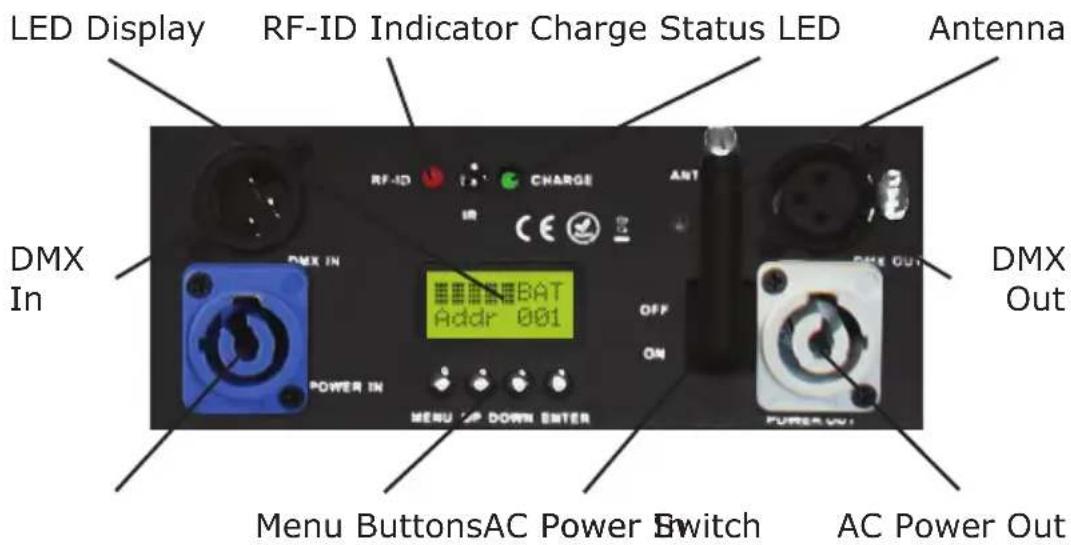
• 3-pin male input and 3-pin female output
- PowerCon™ compatible AC power In/Out connectors
DMX Quick Reference - 11/8 Channel Modes
| Channel 11 | Channel 8-Channel | |
| 1 Dimmer Dimmer | ||
| 2 Red Intensity | Red Intensity | |
| 3 Green Intensity | Green Intensity | |
| 4 Blue Intensity | Blue Intensity | |
| 5 Amber Intensity | Amber Intensity | |
| 6 White Intensity | White Intensity | |
| 7 UV Intensity | UV Intensity | |
| 8 Strobe Strobe | ||
| 9 Static Colors | + Auto Run --- | |
| 10 | Built-in Programs | --- |
| 11 | 32-Bit Dimmer | --- |
DMX Quick Reference - 7/6 Channel Modes
| Channel 7-Channel | 6-Channel | |
| 1 | Red Intensity | Red Intensity |
| 2 | Green Intensity | Green Intensity |
| 3 | Blue Intensity | Blue Intensity |
| 4 | Amber Intensity | Amber Intensity |
| 5 | White Intensity | White Intensity |
| 6 | UV Intensity | UV Intensity |
| 7 | Strobe | --- |
Figure 1: The SkyBox™ EXA Pin-Up Picture
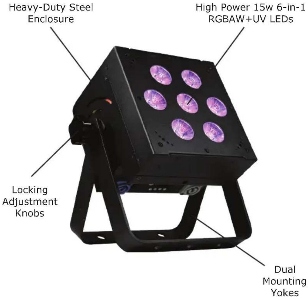
Figure 2: The Rear Connections
3. SETUP

Before replacing a fuse, disconnect power cord. ALWAYS replace with the same type and rating of fuse.
Fuse Replacement
CAUTION! The SkyBox™ EXA utilizes a high-output switch-mode power supply with an internal fuse. Under normal operating conditions, the fuse should not require replacement. The fuse is field replaceable, however it is an advanced procedure suited to qualified individuals. Should your Weather System™ fuse require replacement, please contact Blizzard Lighting for instructions, or to return for service.
Connecting A Bunch of SkyBox EXA™ Fixtures
You will need a serial data link to run light shows using a DMX-512 controller or to run shows on two or more fixtures set to sync in master/slave operating mode. The combined number of channels required by all the fixtures on a serial data link determines the number of fixtures the data link can support.
Fixtures on a serial data link must be daisy chained in one single line. Also, connecting more than 32 fixtures on one serial data link without the use of a DMX optically-isolated splitter may result in deterioration of the digital DMX signal. The maximum recommended cable-run distance is 500 meters (1640 ft). The maximum recommended number of fixtures on a serial data link is 32 fixtures.
Data/DMX Cabling
To link fixtures together you'll need data cables. You should use data-grade cables that can carry a high quality signal and are less prone to electromagnetic interference.
For instance, Belden© 9841 meets the specifications for EIA RS-485 applications. Standard microphone cables will "probably" be OK, but note that they cannot transmit DMX data as reliably over long distances. In any event, the cable should have the following characteristics:
2-conductor twisted pair plus a shield
Maximum capacitance between conductors - 30 pF/ft.
Maximum capacitance between conductor & shield - 55 pF/ft.
Maximum resistance of 20 ohms / 1000 ft.
Nominal impedance 100 - 140 ohms
Cable Connectors
Cables must have a male XLR connector on one end and a female XLR connector on the other end. (Duh!)
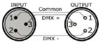
A Word on Termination: DMX is a resilient communication protocol, however errors still occasionally occur. Termination reduces signal errors, and therefore best practices include use of a terminator in all circumstances. If you are experiencing problems with erratic fixture behavior, especially over long signal cable runs, a terminator may help improve performance.
To build your own DMX Terminator: Obtain a 120-ohm, 1/4-watt resistor, and wire it between pins 2 & 3 of the last fixture. They are also readily available from specialty retailers.
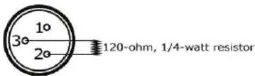
CAUTION: Do not allow contact between the common and the fixture's chassis ground. Grounding the common can cause a ground loop, and your fixture may perform erratically. Test cables with an ohm meter to verify correct polarity and to make sure the pins are not grounded or shorted to the shield or each other.
3-Pin??? 5-Pin??? Huh?!?
If you use a controller with a 5 pin DMX output connector, you will need to use a 5 pin to 3 pin adapter. They are widely available over the internet and from specialty retailers. If you'd like to build your own, the chart below details a proper cable conversion:
| Conductor 3-Pin Female (Output) | 5-Pin Male (Input) |
| Ground/Shield Pin 1 Pin 1 | |
| DMX Data (-) Pin 2 Pin 2 | |
| DMX Data (+) Pin 3 Pin 3 | |
| Not Used. No Connection. No Connection. | |
| Not Used. No Connection. No Connection. |
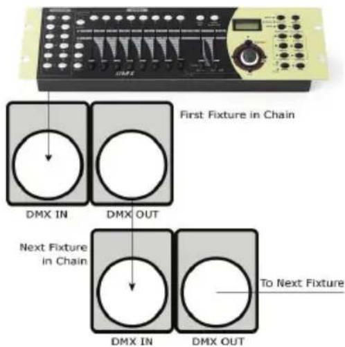
Take It To The Next Level: Setting Up DMX Control
Step 1: Connect the male connector of the DMX cable to the female connector (output) on the controller.
Step 2: Connect the female connector of the DMX cable to the first fixture's male connector (input). Note: It doesn't matter which fixture address is the first one connected. We recommend connecting the fixtures in terms of their proximity to the controller, rather than connecting the lowest fixture number first, and so on.
Step 3: Connect other fixtures in the chain from output to input as above. Place a DMX terminator on the output of the final fixture to ensure best communication.
Fixture Linking (Master/Slave Mode)
- Connect the (male) 3 pin connector side of the DMX cable to the output (female) 3 pin connector of the first fixture.
- Connect the end of the cable coming from the first fixture which will have a (female) 3 pin connector to the input connector of the next fixture consisting of a (male) 3 pin connector. Then, proceed to connect from the output as stated above to the input of the following fixture and so on.
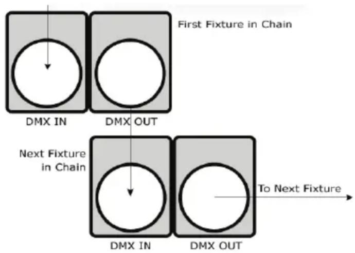
A quick note: Often, the setup for Master-Slave and Standalone operation requires that the first fixture in the chain be initialized for this purpose via either settings in the control panel or DIP-switches. Secondarily, the fixtures that follow may also require a slave setting.
Check the "Operating Adjustments" section in this manual for complete instructions for this type of setup and configuration.
Mounting & Rigging
This fixture may be mounted in any SAFE position provided there is enough room for ventilation.
It is important never to obstruct the fan or vents pathway. Mount the fixture using a suitable "C" or "O" type clamp. The clamp should be rated to hold at least 10x the fixture's weight to ensure structural stability. Do not mount to surfaces with unknown strength, and ensure properly "rated" rigging is used when mounting fixtures overhead.
Adjust the angle of the fixture by loosening both knobs and tilting the fixture. After finding the desired position, retighten both knobs.
- When selecting installation location, take into consideration lamp replacement access (if applicable) and routine maintenance.
- Safety cables MUST ALWAYS be used.
- Never mount in places where the fixture will be exposed to rain, high humidity, extreme temperature changes or restricted ventilation.
Using the AnyFi™ Wireless DMX Receiver
In addition to the unbridled thrill you already received the first time you turned on your fixture, you'll be delighted to know that your fixture is equipped to work seamlessly with our own Skywire™ 2.4GHz wireless DMX products, as well as W-DMX™ wireless products.
Skywire™ AnyFi™ wireless DMX products feature 512 auto-assigning frequencies in either 6 or 7 groups allowing multiple systems to run simultaneously in the same space, completely free of interference, with reliable wireless communication for over 1000 feet line-of-sight! Using the W-DMX™ wireless protocol in AnyFi™, you can expect the same outstanding wireless range, very easy setup, and leave any worries behind concerning loss of signal due to its built-in FHSS technology (Frequency Hopping Spread Spectrum).

Universal Wireless DMX
So first, if you would like to use Skywire™ wireless DMX protocol, you will need a wiCICLE® transmitter, Lightcaster™ transceiver, or any Blizzard Lighting controller with this type of built-in wireless transmitter. And if you plan on using W-DMX™ 2.4GHz wireless protocol, you will need a W-DMX™ transceiver to broadcast the signal from your controller, such as our Lightcaster W-DMX™.
Ready to move on? Well alrighty!
IMPORTANT - If you are using Blizzard's Lightcaster Any-Fi wireless transmitter in W-DMX compatibility mode along with DMX control software like our Eclipse DMX or Lucid products, you must set the MAB (Mark After Break) in the software to 30 microseconds ( S) to avoid potential signal timing issues.
1.) Set the Fixture to Receive Wireless Signal in the Control Panel
a.) Navigate the main menu to reach Signal, press
2.) Select W-DMX ^TM or Skywire ^TM Modes
a.) Make sure the device you are using to transmit signal with is powered on.
b.) Navigate the main menu to reach WIRELESS, press
c.) Now use the
d.) At this point, please note that every time you press the
- GREEN: W-DMX™ 2.4 GHz Receiver Mode
- YELLOW: Skywire™ 7CH Receiver Mode (wiCICLE™ & LightCaster Compatible)
- RED: Skywire™ 6CH Receiver Mode (AnyFi™ Transmitter Compatible)
*Note: The top level BLUE channel mode currently has no function.
e.) While the LED indicator is illuminated in GREEN (for W-DMX), YELLOW (for Skywire 7CH), or RED (for Skywire 6CH) press and hold the
For W-DMX ^™ connections, you should be done. The fixture will detect the signal!
*For Skywire™ wireless connections, continue to Step 5 on the next page.
3.) Resetting The Wireless
Note: You should reset the wireless before setting up a new types of connections on previously connected fixture.
a.) Navigate the main menu to reach WIRELESS, press
a.) Use the
b.) From here, you can use the
4.) Successful W-DMX ^TM Connections
The LED status indicator will blink, then turn white if searching for a signal. When a signal connection is established, the LED on the fixture will be solid GREEN, if signal is lost the LED will flash RED.
W-DMX™ Setup Examples:
1.) One transceiver with multiple receiver setups:
a.) Power on all units.
b.) On the receiving W-DMX fixtures, follow the previous instructions to pair them with the transmitting unit.
2.) Multiple transceiver setups, with multiple receivers; e.g. 3 groups consisting of a transceiver & receiver(s) named A, B, and C:
a.) Turn power off of all units.
b.) Group "A" gets powered on, then follow step 1 above.
c.) Group "B" gets powered on, then follow step 1 above.
d.) Group "C" gets powered on, then follow step 1 above.
5.) Skywire™ 6/7-Channel Modes: Selecting the Channel Group
- After selecting either Skywire™ Mode in Step 2 on the previous page, the fixture is now ready and waiting for your input to select the frequency group to match that of your transmitting source.
a.) Press the
| Top Menu LED Color | Mode | Channel LED Color | Information | |
| SkywireTM 6CH (AnyFiTM products only) | CH1 | These 6 color coded channels match perfectly with other AnyFiTM wireless products while using SkywireTM 6CH mode. | ||
| CH2 | ||||
| CH3 | ||||
| CH4 | ||||
| CH5 | ||||
| CH6 | ||||
| W-DMX Receive (G3 or G4) | ||||
| SkywireTM 7CH (wiCICLETM compatible) | CH1 | These channel numbers correspond to the "GROUP" settings on our LightCasterTM wireless DMX transceiver, and the colored channels match all wiCICLETM and SkywireTM wireless products. | ||
| CH2 | ||||
| CH3 | ||||
| CH4 | ||||
| CH5 | ||||
| CH6 | ||||
| CH7 | ||||
b.) While your chosen group number/color is illuminated on the status LED, press and hold the
- The LED on the transmitter will blink RED slowly until communication is established with the receiver. The status LED on the receiving fixtures will be illuminated in the color of the group that it is set on until communication is established.
- Once the clearest channel is auto-selected, the status LEDs will blink quickly on both the transmitter and receiver. NOTE: The color of the status LED DURING operation does not indicate channel group, instead it indicates whether the unit is transmitting or receiving. That's It!
Possible Configurations
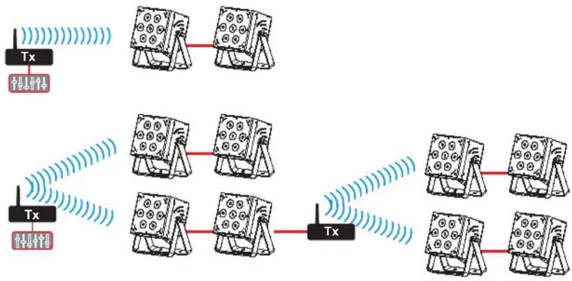
The diagrams below show possible configurations. Multiple units may be used in any possible configuration.
flowchart
graph TD
    A["Tx"] --> B["Receiver"]
    B --> C["Tx"]
    C --> D["Receiver"]
    D --> E["Tx"]
    E --> F["Receiver"]
    F --> G["Tx"]
    style A fill:#f9f,stroke:#333
    style G fill:#f9f,stroke:#333
    style B fill:#ccf,stroke:#333
    style C fill:#ccf,stroke:#333
    style D fill:#ccf,stroke:#333
    style E fill:#ccf,stroke:#333
    style F fill:#ccf,stroke:#333
    style G fill:#ccf,stroke:#333
Using the Intelion™ Battery System
The SkyBox™ EXA features our proprietary Intelion™ Lithium-Ion internal battery system which allows you the flexibility to operate your fixture without AC power for up to 20 hours.
To charge the battery, simply plug the fixture into a power source. The battery will charge weather the fixture is powered on or off. It will even charge while in use! The built-in microprocessor of the battery system controls the charge and overall battery health, so all you need to do is plug and play.
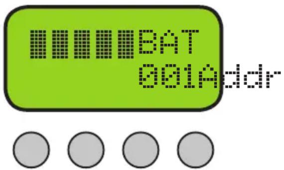
The top section on the LCD display menu shows the battery power level indicator displays the approximate amount of power remaining in the battery. Each power level bar equals 20%. When charging, The CHARGE status LED above the LCD display will illuminate in RED, then turn GREEN when the charge is complete.

A full charge is obtained after charging for at least 4 hours. The fixture will automatically stop charging when the battery is in optimal condition.
Power Output Mode:
Depending on the needs of any given application, you can select either High Power, Medium Power, or Battery Saver Mode, which allows the fixture to run for a longer time at lower output.
a.) Navigate the menu to reach BATMOD, and press
b.) Use the
c.) Press
Note: With average usage of color fades in High Output Mode, you can expect the battery life to last up to 10+ hours, color jumping 5+ hrs, or full on for 3+ hrs. Display color/fade/chase/strobe, and environmental factors including ambient temperature will all impact battery life.
4. OPERATING ADJUSTMENTS
The Control Panel
All the goodies and different modes possible with the SkyBox™ EXA are accessed by using the control panel on the rear of the fixture. There are 4 control buttons below the LCD display which allow you to navigate through the various control panel menus.
Is used to navigate to the previous higher-level menu item.
Scrolls through menu items and numbers in ascending order.
Scrolls through menu items and numbers in descending order.
Is used to select and confirm/store the current selection.
MENU UP DOWN ENTER
The Control Panel LCD Display shows the menu items you select from the menu map on page #15. When a menu function is selected, the display will show immediately the first available option for the selected menu function. To select a menu item, press
Press the
- TABLE OF CONTENTS
- Getting Started
- Meet The SkyBox™ EXA 6
- Setup 8
- Operating Adjustments
- Appendix 2
- LITHIUM-ION BATTERY WARNINGS & INFO
- What's In The Box?
- Getting It Out Of The Box
- Powering Up!
- Getting A Hold Of Us
- SAFETY INSTRUCTIONS
- MEET THE SKYBOX™ EXA LED PAR
- CONTROL FEATURES
- ADDITIONAL FEATURES
- SETUP
- Fuse Replacement
- Connecting A Bunch of SkyBox EXA™ Fixtures
- Data/DMX Cabling
- Cable Connectors
- 3-Pin??? 5-Pin??? Huh?!?
- Take It To The Next Level: Setting Up DMX Control
- Fixture Linking (Master/Slave Mode)
- Mounting & Rigging
- Using the AnyFi™ Wireless DMX Receiver
- Ready to move on? Well alrighty!
- 1.) Set the Fixture to Receive Wireless Signal in the Control Panel
- 2.) Select W-DMX TM or Skywire TM Modes
- 3.) Resetting The Wireless
- 4.) Successful W-DMX TM Connections
- W-DMX™ Setup Examples:
- 5.) Skywire™ 6/7-Channel Modes: Selecting the Channel Group
- Possible Configurations
- Using the Intelion™ Battery System
- Power Output Mode:
- The Control Panel
- Control Panel Menu Structure
- DMX Mode
- Set the Starting DMX Address:
- Select the DMX Channel Mode:
- Auto Mode / Static Colors
- Speed:
- Fade:
- Strobe (White)
- Manual Color Mixing:
- Red:
- Green:
- Blue:
- Amber:
- White:
- UV:
- Sound Active Mode
- Dimming Mode
- Power Output Mode
- Using the IR Remote Control (sold separately)
- APPENDIX
- A Quick Lesson On DMX
- Keeping Your SkyBox™ EXA As Good As New
- Returns (Gasp!)
- Shipping Issues
- Tech Specs!
- DISCLAIMER:
- Dimensional Drawings
Brand : Blizzard Lighting
Model : SkyBox EXA
Category : Machine à effets