DW-ENC4K16 - Video Surveillance Digital Watchdog - Free user manual and instructions
Find the device manual for free DW-ENC4K16 Digital Watchdog in PDF.


| Product Type | 16-Channel Analog to IP Video Encoder |
| Brand / Model | Digital Watchdog DW-ENC4K16 |
| Video Input | 16 BNC; supports HD-TVI, HD-Analog, HD-CVI, CVBS up to 960H |
| Video Output | True HD (3840x2160), VGA (1920x1080), BNC (CVBS, 960H) |
| Compression | H.265 / H.264 |
| Max Recording Resolution | 4K at 15fps per channel (main stream) |
| Audio | 8 RCA inputs, 1 RCA output; G.711 codec |
| Alarm I/O | 16 alarm inputs, 4 alarm outputs |
| Network Interface | 1x RJ45 10/100/1000 Base-T |
| Power Requirement | 12V DC, 4A |
| Power Consumption | Max 30W, 2.5A |
| Dimensions (W x D x H) | 14.96" x 10.55" x 1.77" (380 x 268 x 45 mm) |
| Operating Temperature | 14°F to 122°F (-10°C to 50°C) |
| Humidity | 10-90% non-condensing |
| Certifications | CE, FCC, NDAA |
| Warranty | 2 years |
| Supported Protocols | TCP/IP, DHCP, DNS, DDNS, UPnP, HTTP, NTP, SMTP, RTSP, SNMP, FTP, ONVIF |
| Remote Access | Web browser (Edge, Chrome, Firefox, Safari) and DW Spectrum IPVMS |
| Mounting | 19" rack mount ear kit included (DW-G419RE) |
| Maintenance | Clean with dry cloth; ensure ventilation; update firmware regularly |
| Safety / Cybersecurity | Strong password, firewall, HTTPS, block/allow lists, disable UPnP if unused |
Frequently Asked Questions - DW-ENC4K16 Digital Watchdog
User questions about DW-ENC4K16 Digital Watchdog
0 question about this device. Answer the ones you know or ask your own.
Ask a new question about this device
Download the instructions for your Video Surveillance in PDF format for free! Find your manual DW-ENC4K16 - Digital Watchdog and take your electronic device back in hand. On this page are published all the documents necessary for the use of your device. DW-ENC4K16 by Digital Watchdog.
USER MANUAL DW-ENC4K16 Digital Watchdog
Analog to IP Video Encoder
DW-ENC4K16

natural_image
Front view of a black electronic device labeled 'DW' with ventilation grille and ports (no readable text beyond branding)Default Admin Login Information
When logging into the encoder for the first time, you must set up a new password. This admin password will be used for the ONVIF connection. Only the admin account will be used for ONVIF connection.
※ The picture might differ according to the specification and model.
※ Contents of this user manual are protected under copyrights and computer program laws.
Before operating the system, please read this User Manual and retain it for future reference.
Rev: 02/24
Notes
- Please read this user manual carefully to ensure that you can use the device correctly and safely.
- There may be several technically incorrect places or printing errors in this manual. The updates will be added to the new version of this manual. The contents of this manual are subject to change without notice.
- This device should be operated only from the type of power source indicated on the marking label. The voltage of the power must be verified before using it. Kindly remove the cables from the power source if the device is not to be used for a long period of time.
- Do not install this device near any heat sources such as radiators, heat registers, stoves or other devices that produce heat.
- Do not install this device near water. Clean only with a dry cloth.
● Do not block any ventilation openings and ensure proper ventilation around the machine. - Do not power off the device at normal recording conditions.
- This machine is for indoor use only. Do not expose the machine to rain or a moist environment. In case any solid or liquid gets inside the machine's case, please turn off the device immediately and get it checked by a qualified technician.
- Do not try to repair the device by yourself without technical aid or approval.
- In this manual, the trademarks, product names, service names, company names, and products that our company does not own are the properties of their respective owners.
- It is recommended to back up and clear the personal data stored in the device before the device is returned to us for repair or replacement, except those data that are essential for purposes of repair or replacement. The device will be restored to the default factory settings, and all personal data will be cleared after repair or replacement. Our company ensures that the customer's data is not made available to third parties if the device is exchanged.
- This manual is suitable for many models. All examples and pictures used in the manual are from one of the models for reference purposes.
- The local language versions of this manual will be provided to users in the corresponding regions and countries.
Disclaimer
- Regarding the product with internet access, the use of the product shall be wholly at your own risk. Our company shall be irresponsible for abnormal operation, privacy leakage or other damages resulting from cyber-attacks, hacker attacks, virus inspection, or other internet security risks; however, our company will provide timely technical support if necessary.
● Surveillance laws vary from country to country. Check all laws in your local region before
using this product for surveillance purposes. We shall not take responsibility for any consequences resulting from illegal operations. In the event of any conflicts between this manual and the applicable law, the latter prevails.
- The storage of personal data depends on the capacity of the storage devices the users use, and all data stored in the device shall be handled by themselves. Our company shall not be responsible for the data loss.
Cybersecurity Recommendations
- Use a strong password. At least 8 characters or a combination of characters, numbers, and upper- and lower-case letters should be used in your password.
- Set the password expiration time and regularly change the passwords of your devices to ensure that only authorized users can access the system (the recommended time is 90 days).
- The system will automatically check the latest firmware version once a day. Once the latest version is checked, you'd better update it to ensure the system is current with the latest security patches and fixes.
- It is recommended to change the service default ports (like HTTP-80, HTTPS-443, etc.) to reduce the risk of outsiders being able to access.
- It is recommended to set your router's firewall. But note that some important ports cannot be closed (like HTTP port, HTTPS port, Data Port).
- Exposing the device to the public network is not recommended. When it is necessary to be exposed to the public network, please set the external hardware firewall and the corresponding firewall policy.
- It is not recommended to use the v1 and v2 functions of SNMP.
- To enhance the security of WEB client access, please create a TLS certificate to enable HTTPS.
- Use the black- and allowlist to filter the IP address. This will prevent everyone, except those specified IP addresses, from accessing the system.
- If you add multiple users, please limit the functions of guest accounts.
- If you enable UPnP, it will automatically try to forward ports in your router or modem. It is very convenient for users, but this will increase the risk of data leakage when the system automatically forwards ports. Disabling UPnP is recommended when the function is not used in real applications.
- Check the log. If you want to know whether your device has been accessed by unauthorized users or not, you can check the log. The system log will show you which IP addresses were used to log in to your system and what was accessed.
Regulatory Information
FCC Information
- FCC compliance: The products have been tested and found to be in compliance with the council FCC rules and regulations Part 15 Subpart B. These limits are designed to provide reasonable protection against harmful interference. This equipment generates uses and can radiate radio frequency energy and, if not installed and used in accordance with the instruction manual, may cause harmful interference to radio communication. However, there is no guarantee that interference will not occur in a particular installation. The user will be required to correct the interface at his own expense in case harmful interference occurs.
- FCC conditions: Operation of this product is subject to the following two conditions: (1) this device may not cause harmful interface, and (2) this device must accept any interference received, including interference that may cause undesired operation.
CE Information
CE The products have been manufactured to comply with the following directives. EMC Directive 2014/30/EU
RoHS
The products have been designed and manufactured in accordance with Directive EU RoHS Directive 2011/65/EU and its amendment Directive EU 2015/863 on the restriction of the use of certain hazardous substances in electrical and electronic equipment.

2012/19/EU (WEEE directive): The Directive on waste electrical and electronic equipment (WEEE Directive). To improve the environmental management of WEEE, the improvement of collection, treatment and recycling of electronics at the end of their life is essential. Therefore, the product marked with this symbol must be disposed of responsibly.
Directive 94/62/EC: The Directive aims to manage packaging and packaging waste and promote environmental protection. The packaging and packaging waste of the product in this manual refers to must be disposed of at designated collection points for proper recycling and environmental protection.
REACH (EC1907/2006): REACH concerns the Registration, Evaluation, Authorization and Restriction of Chemicals, which aims to ensure a high level of protection of human health and the environment through better and earlier identification of the intrinsic properties of chemical substances. The product in this manual refers to conforms to the rules and regulations of REACH. For more information on REACH, please refer to DG GROWTH or ECHA websites.
Table of Contents
1 Introduction....3
1.1 What's in the Box....3
1.2 Connections....3
2 Basic Operation Guide....6
2.1 Startup and Shutdown....6
2.1.1 Startup....6
2.1.2 Shutdown....6
2.2 Mouse Control....6
2.3 Text-input Instruction....7
2.4 Common Button Operation....7
3 Wizard & Main Interface....8
3.1 Startup Wizard 8
3.2 Main Interface....10
4 Camera Management....12
4.1 Camera Signal....12
4.2 Edit Camera....12
5 Live View Introduction....13
5.1 Live View Interface Introduction....13
5.2 Image Configuration ....14
5.2.1 Encoder Parameters....14
5.2.2 Image Settings....15
5.2.3 Mask Settings....16
6 PTZ....17
6.1 PTZ Control Interface Introduction....17
6.2 Preset Setting....18
6.3 PTZ Protocol Setting....19
7 Event Management....20
7.1 Sensor Alarm....20
7.2 Motion Alarm....21
7.2.1 Motion Configuration....22
7.2.2 Motion Alarm Handling Configuration....23
7.3 Video Loss Settings....24
7.4 Exception Handling Settings ....25
7.5 Alarm Event Notification....25
7.5.1 E-mail 25
7.5.2 Display 25
7.5.3 Buzzer 26
7.6 View Alarm Status....27
8 Account & Permission Management....28
8.1 Account Management 28
8.1.1 Add User....29
8.1.2 Edit User 30
8.2 User Login & Logout 31
8.3 Permission Management....31
8.3.1 Add Permission Group .... 31
8.3.2 Edit Permission Group....32
8.4 Block and Allow Lists....33
8.5 Preview On Logout....34
8.6 Password Security ....34
8.7 View Online User 35
9 Device Management....36
9.1 Network Configuration....36
9.1.1 TCP/IP Configuration ....36
9.1.2 Port Configuration....36
9.1.3 DDNS Configuration....38
9.1.4 E-mail Configuration....41
9.1.5 UPnP Configuration....42
9.1.6 802.1X 43
9.1.7 FTP Configuration 44
9.1.8 SNMP 44
9.1.9 ONVIF 45
9.1.10 View Network Status....46
9.2 Basic Configuration....46
9.2.1 Common Configuration....46
9.2.2 Date and Time Configuration....47
9.3 Factory Default 48
9.4 Device Software Upgrade ....48
9.5 Backup and Restore....48
9.6 Restart Automatically....49
9.7 View Log 49
9.8 View System Information....50
10 Remote Surveillance....51
10.1 Web LAN Access ....51
10.2 Web WAN Access....51
10.3 Web Remote Control 52
10.3.1 Remote Preview 53
10.3.2 Remote Configuration....56
11 Specifications....57
12 Warranty Information....59
13 Limits and Exclusions 60
1 Introduction
1.1 What's in the Box
Make sure that you have the following items supplied with your encoder. If any of these items are missing or damaged, notify your vendor immediately. Keep the packing utilities for moving or storage purposes afterward.
| WHAT'S IN THE BOX | ||||||
| Quick Setup and Download Guides |  | 1 set | Power Cable | 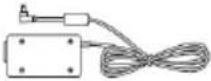 | 1 set | |
| 19" Rack Mount Ears and Mounting Screws (DW-G419RE) |  | 1 set | USB Mouse |  | 1 | |
1.2 Connections
Follow the diagram below to connect all necessary external devices to your encoder. Please note that the number of ports available may differ based on the model. See the product's specifications at the end of this manual for more information.
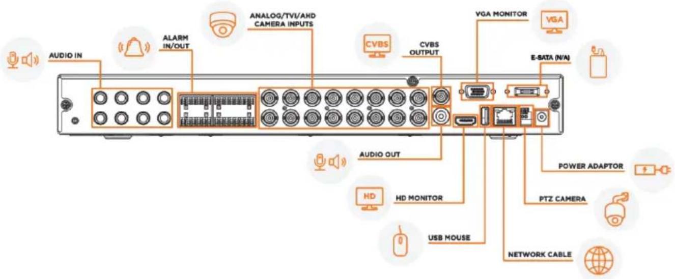
• Video Connections
Video Output: The encoder supports VGA and True HD video output for local display. You can connect to a monitor (not included) through these video output interfaces simultaneously or independently.
• Audio Connections
Audio Input: Connect to microphone, pickup, etc. (RCA)
Audio Output: Connect to headphones, sound box or other audio output devices. (RCA)
- Alarm Connections
Some models may support this function. Take 16 CH alarm inputs and 1 CH alarm output, for example.
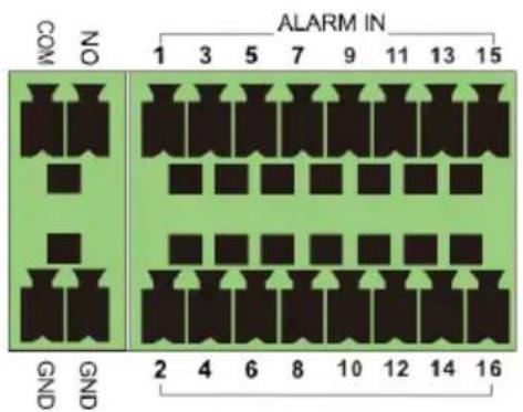
- Alarm Input:
Alarm IN 1\~16 are 16 CH alarm input interfaces. There are no type requirements for sensors. NO type and NC type are both available.
The way to connect the sensor and the device is as shown below:
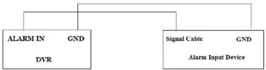
flowchart
graph TD
    A["ALARM IN"] --> B["DVR"]
    C["Signal Cable"] --> D["Alarm Input Device"]
    E["GND"] --> F["Alarm Input Device"]
    style A fill:#f9f,stroke:#333
    style C fill:#f9f,stroke:#333
    style E fill:#ccf,stroke:#333
The alarm input is an open/closed relay. If the input is not an open/closed relay, please refer to the following connection diagram:
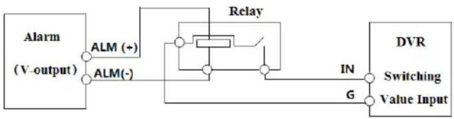
flowchart
graph LR
    A["Alarm (V-output)"] --> B["ALM (+)"]
    A --> C["ALM(-)"]
    B --> D["Relay"]
    C --> D
    D --> E["DVR"]
    E --> F["Switching"]
    E --> G["Value Input"]
    H["IN"] --> E
    I["G"] --> E
- Alarm Output:
To connect an alarm output device:
Pull out the green terminal blocks and loosen the screws in the alarm-out port. Then, insert the signal wires of the alarm output devices into the ports of NO and COM separately. Finally, tighten the screws. Provided that the external
alarm output devices need a power supply, you can connect the power supply as per the following figures.
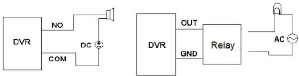
flowchart
graph TD
    A["DVR"] -->|NO| B["DC"]
    A -->|COM| C["DC"]
    B --> D["Speaker"]
    C --> E["DC"]
    D --> F["OUT"]
    E --> G["GND"]
    F --> H["Relay"]
    G --> H
    H --> I["AC"]
    I --> J["Ground"]
• RS485 Connection
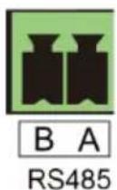
The RS485 interface is used to connect a keyboard.
Disconnect the pluggable block from the RS485 terminal block and loosen the fixed screws from the pluggable block. Insert signal cables into A and B ports separately (A is TX+; B is TX-) and tighten the fixed screws. Next, connect the pluggable block back into the terminal block.
**NOTE: The pluggable block of some models may not be connected into the terminal block, and you shall obtain it from the accessories.
2 Basic Operation Guide
2.1 Startup and Shutdown
Please make sure all external devices are connected properly before powering the unit. Proper startup and shutdown are crucial to extending the life of your device.
2.1.1 Startup
- Connect the output display device to the VGA/true HD interface of the encoder.
- Connect the mouse and power. The device will boot, and the power LED will turn blue.
- A WIZARD window will pop up (you should select the display language the first time you use the encoder). Refer to the Startup Wizard (Section 3.1) portion of this guide for details.
2.1.2 Shutdown
You can power off the device by using a mouse.
By mouse:
-
Click Start→Shutdown to pop up the Shutdown window. Select "Shutdown" in the window and click the "OK" button. The unit will power off after verifying the username and password.
-
Disconnect the power from the unit.
2.2 Mouse Control
- Mouse control in Live Display interface In the live display & playback interface, double-click on any camera window to show the window in single-screen mode; double-click the window again to restore it to the previous size.
- Mouse control in text input Move the mouse to the text-input box, then click the box. The input keyboard will pop up automatically.
**NOTE: Mouse is the default tool for controlling all operations except for when using a joystick keyboard.
2.3 Text-input Instruction
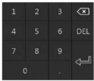
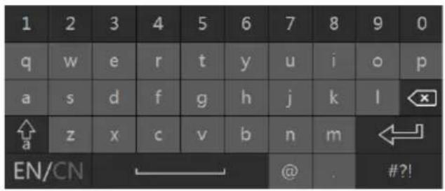
The system includes two input boxes. Refer to the above pictures. The left box is the number input box, and the right box is an alphanumeric digital keyboard input box, which provides inputs of numbers, letters, and punctuation characters. The introductions of keys on the input boxes are shown below.
| Button | Meaning | Button | Meaning |
 | Backspace key |  | Switch key of punctuation character. |
 | Delete Key |  | Enter key |
 | Switch the key between the upper and lower letters. |  | Space key |
 | Switch key of language. | ||
2.4 Common Button Operation
| Button | Meaning | |
 | Click to show the menu list. | |
 | Click to change the sequence of the list. | |
 | Click to close the current interface. | |
3 Wizard & Main Interface
3.1 Startup Wizard
You can quickly configure the encoder by wizard setup. When you initially start the encoder, you will be prompted to configure the system using the startup wizard.
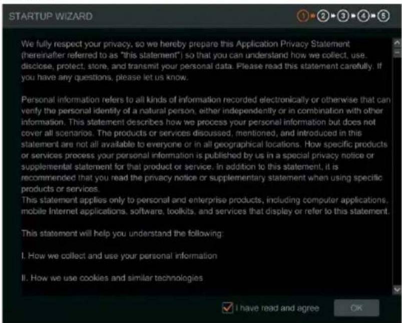
- Read the privacy statement and check "I have read and agree." then click "OK" to continue.
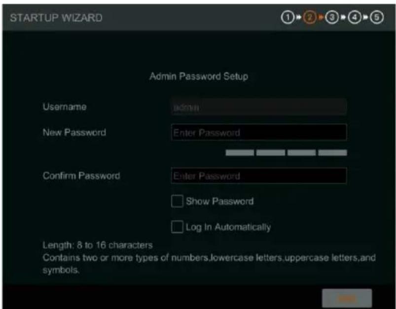
- Set the administrator password. Passwords must be between 8\~16 characters and must contain a combination of at least two or more numbers, letters, or symbols. The default username of the system is “admin” and cannot be changed.
- Choose the language and region for the system.
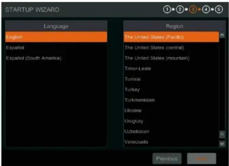
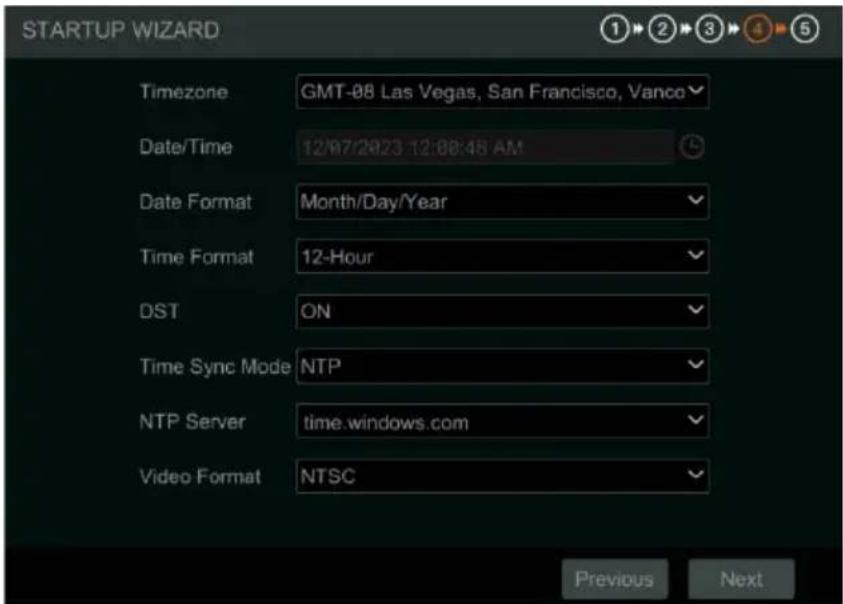
- Date and Time Configuration. The date and time of the system need to be set up. Set the time zone, date/time, date format and time format. The DST will be enabled by default if the time zone selected uses DST. Click "Next" to continue.
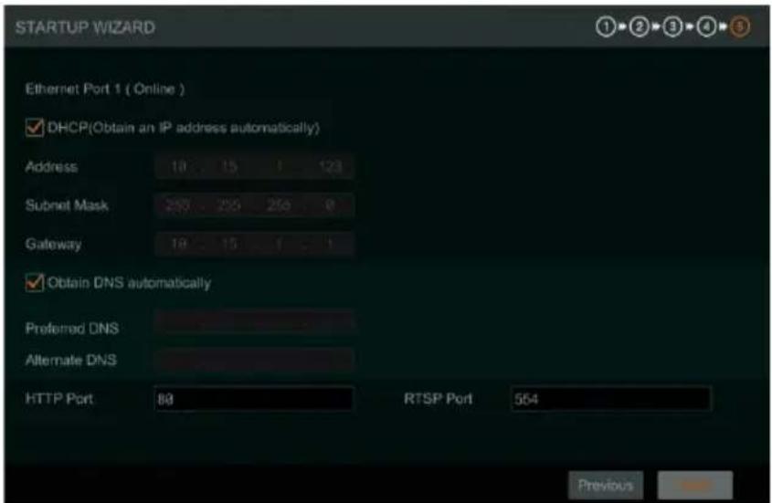
- Network Settings. Check "Obtain an IP address automatically" and "Obtain DNS automatically" to have an IP address and DNS automatically assigned from the local router. The router must be within the same LAN and the DHCP function should also be enabled. Alternatively, you may manually enter network information.
Enter the HTTP port and RTSP port (see Section 9.1.2 Port Configuration for more details).
3.2 Main Interface
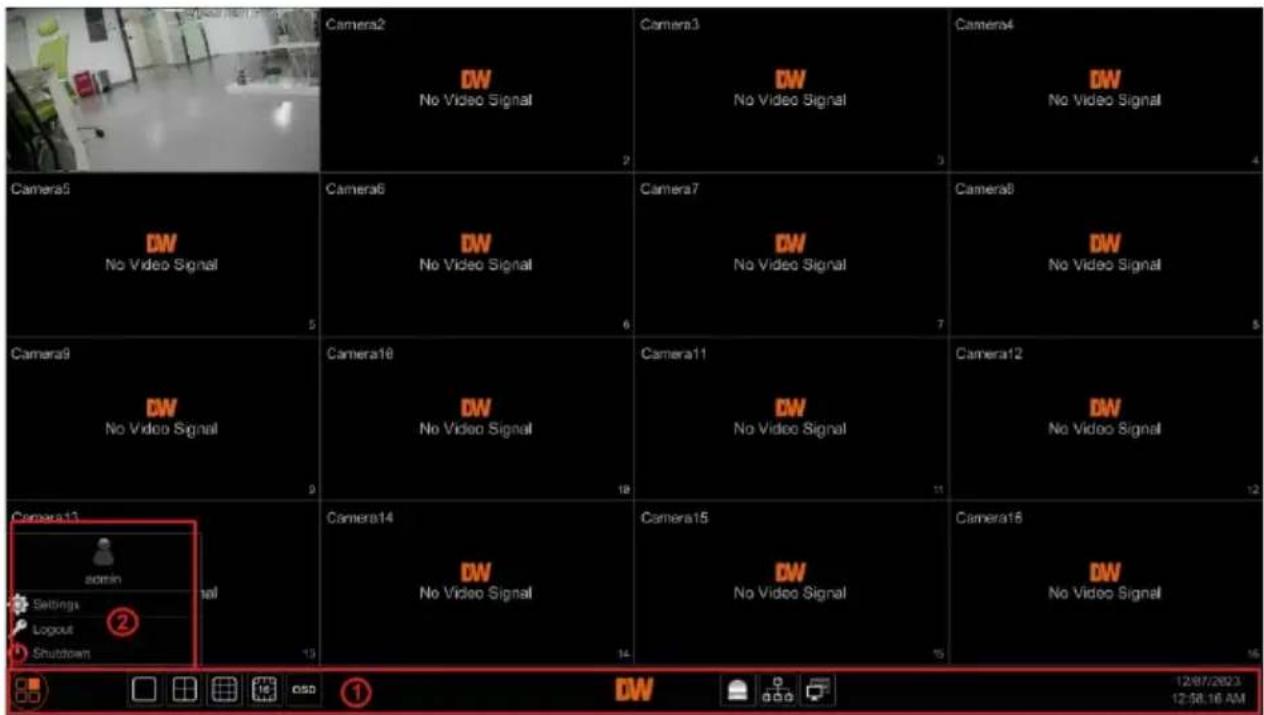
The buttons in area ① are described in the table below.
| Icon / Button | Description | |
 | Start button. Click to display area 2 pop up. | |
 | Screen mode button. Select the number of individual camera channels to display within the main viewing area. | |
Compressor™
| Icon / Button | Description |
 | Click to enable the OSD (on screen display) overlay; click again to disable OSD. |
 | Alarm status button. Click to view the alarm status. |
 | Network status button. Click to view the network status. |
 | Information button. Click to view system information, including basic information, camera status, alarm status, network status, and user status. |
Description of area ②:
| Icon / Button | Description |
 | Shows the current user that is logged in. |
 | Click to pop up the setup panel. |
 | Click to log out of the system. |
 | Click and then select "Logout," "Reboot," or "Shutdown" in the popup window. |
4 Camera Management
4.1 Camera Signal
Click Start→Settings→Camera→Manage Camera→Camera Signal to navigate to the Camera Signal interface as shown below.
The encoder device supports hybrid access to HD-TVI, HD-Analog, HD-CVI and CVBS high-definition cameras. Select the correct video signal type for each camera. For example, if the encoder is connected to an HD-TVI high-definition camera, you should select HD-TVI in the following interface to display the camera image normally. Selecting an incompatible video signal for a camera will result in an unstable image displaying or no image at all. The default selection of the camera signal is Auto. If you select Auto, the image of the camera will be shown normally regardless of the camera type.
| Camera | Analog | ✓ | Signal | ✓ | Lite | ✓ |
| [A01] | Analog | ✓ | Auto(TVI/AHD/CVBS) | ✓ | OFF | ✓ |
| [A02] | Analog | ✓ | Auto(TVI/AHD/CVBS) | ✓ | OFF | ✓ |
| [A03] | Analog | ✓ | Auto(TVI/AHD/CVBS) | ✓ | OFF | ✓ |
| [A04] | Analog | ✓ | Auto(TVI/AHD/CVBS) | ✓ | OFF | ✓ |
| [A05] | Analog | ✓ | Auto(TVI/AHD/CVBS) | ✓ | OFF | ✓ |
4.2 Edit Camera
Click "Edit Camera" in the setup panel to go to the Manage Camera interface as shown below.
![Manage Camera Camera Signal Edit Camera Search Camera Image Encode Parameters Image Settings Mask Settings Motion Motion Settings PTZ Preset | Protocol No. Camera Name Preview Edit 1 [A81]Camera1 2 [A82]Camera2 3 [A83]Camera3 4 [A84]Camera4 5 [A85]Camera5 6 [A86]Camera6 7 [A87]Camera7 8 [A88]Camera8 9 [A89]Camera9 10 [A10]Camera10 11 [A11]Camera11 12 [A12]Camera12 13 [A13]Camera13 14 [A14]Camera14 15 [A15]Camera15 16 [A16]Camera16](/content/2026/05/944199/images/56e9bdc86de729ee80bd74d550416f4c6bd7fb735468255a37c9d839c83e7320.jpg)
Click 🖼️ to view the live image of the camera in the popup window. Click 🔒 to edit the camera name.
5 Live View Introduction
5.1 Live View Interface Introduction
The connected analog camera will be added automatically in the live view interface. To move a camera to a different viewing window, drag one camera from one preview window to another window for camera window exchange.
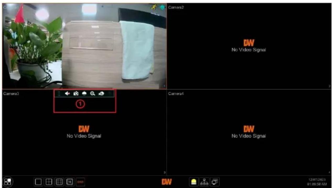
Click the in a preview window to show the toolbar as shown in area ①; right-click the preview window to show the menu list. The toolbar and menu list are described in the table below.
| Icon/Button | Menu List | Description |
 | -- | Move tool. Click and drag to move the toolbar. |
 | Enable Audio | Click to enable audio. You can listen to the camera audio by enabling audio. |
 | Snap | Click to pop up the snap window. Click "Save" in the window to save the image. Click "Export" to export the image. |
 | PTZ Control | Click to go to the PTZ control interface. |
 | Zoom In | Click to go to the single-channel amplification interface. Move the scroll wheel up to zoom in. |
 | -- | Click to go to the image adjustment interface and adjust the appearance of image brightness, contrast, etc. |
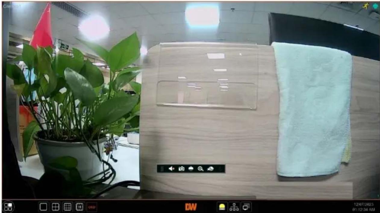
To view a camera channel in a 1x1, full screen display, double-click on the channel in the viewing display.
The single-channel amplification interface is shown below.
natural_image
Interior scene with a potted plant, a wooden display unit, and a cloth towel on a desk (no visible text or symbols)5.2 Image Configuration
5.2.1 Encoder Parameters
Click Start→Settings→Camera→Image→Encoder Parameters to navigate to the following interface.
Set the compression encoder setting, GOP, resolution, FPS, bitrate type, quality, max bitrate, and audio of each camera then click "OK" to save the settings. Please adjust the parameters according to the actual camera's requirements.
Go to Settings→ Network→ Stream Settings to set the sub-stream parameters.
| Camera Name | Stream Type | Encode | Resolution | FPS | Bitrate Type | Quality | Max Bitrate | Bitrate Limit Recommended Range | Audio |
| Camera1 | Main Stream | H.265 | 1928x100 | 30 | VBR | Higher- | 2848Kbps | 2838-4716Kbps | ON |
| Camera2 | Main Stream | H.265 | 352x240 | 7 | VBR | Higher- | 256Kbps | 36-61Kbps | ON |
| Camera3 | Main Stream | H.265 | 352x240 | 7 | VBR | Higher- | 256Kbps | 36-61Kbps | ON |
| Camera4 | Main Stream | H.265 | 352x240 | 7 | VBR | Higher- | 256Kbps | 36-61Kbps | ON |
| Camera5 | Main Stream | H.265 | 352x240 | 7 | VBR | Higher- | 256Kbps | 36-61Kbps | ON |
| Camera6 | Main Stream | H.265 | 352x240 | 7 | VBR | Higher- | 256Kbps | 36-61Kbps | ON |
| Camera7 | Main Stream | H.265 | 352x240 | 7 | VBR | Higher- | 256Kbps | 36-61Kbps | ON |
| Camera8 | Main Stream | H.265 | 352x240 | 7 | VBR | Higher- | 256Kbps | 36-61Kbps | ON |
| Camera9 | Main Stream | H.265 | 352x240 | 7 | VBR | Higher- | 256Kbps | 36-61Kbps | |
| Camera10 | Main Stream | H.265 | 352x240 | 7 | VBR | Higher- | 256Kbps | 36-61Kbps | |
| Camera11 | Main Stream | H.265 | 352x240 | 7 | VBR | Higher- | 256Kbps | 36-61Kbps | |
| Camera12 | Main Stream | H.265 | 352x240 | 7 | VBR | Higher- | 256Kbps | 36-61Kbps | |
| Camera13 | Main Stream | H.265 | 352x240 | 7 | VBR | Higher- | 256Kbps | 36-61Kbps | |
| Camera14 | Main Stream | H.265 | 352x240 | 7 | VBR | Higher- | 256Kbps | 36-61Kbps | |
| Camera15 | Main Stream | H.265 | 352x240 | 7 | VBR | Higher- | 256Kbps | 36-61Kbps |
- Encode: determines the video encoding/compression format of each camera.
- Resolution: determines the general clarity of the video; the higher the resolution is set as, the clearer the image will appear.
- FPS: determines the number of frames per second that will appear during streaming; the higher the frame rate is, the smoother the video will appear.
- Bitrate Type: CBR and VBR are optional. CBR means that no matter how much change is seen in the video scene, the compression bitrate will be kept constant. VBR means that the compression bitrate will be adjusted according to scene changes. For example, for scenes that do not have much movement, the bitrate will be kept at a lower value. This will help to optimize the network bandwidth.
• Quality: When VBR is selected, you need to choose image quality. The higher the image quality you choose, the more bitrate will be required.
- GOP: setting for "group of pictures"; determines the number of frames that appear during video streaming. It is recommended to set the GOP setting to the same value as FPS settings.
5.2.2 Image Settings
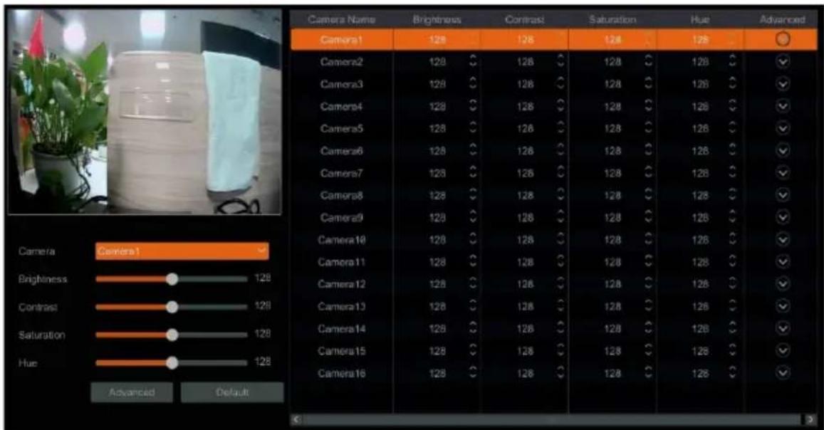
Click Start→Settings→Camera→Image→Image Settings to go to the Image Settings interface. Select the camera then set the brightness, contrast, saturation, and hue settings to adjust how camera video will appear through the encoder.
Click the "Advanced" button or in the camera list, on the right side of the interface, to pop up the "Image Adjust" interface to set the relevant settings.
You can click the "Default" button to restore the image settings to the encoder's factory settings.
5.2.3 Mask Settings
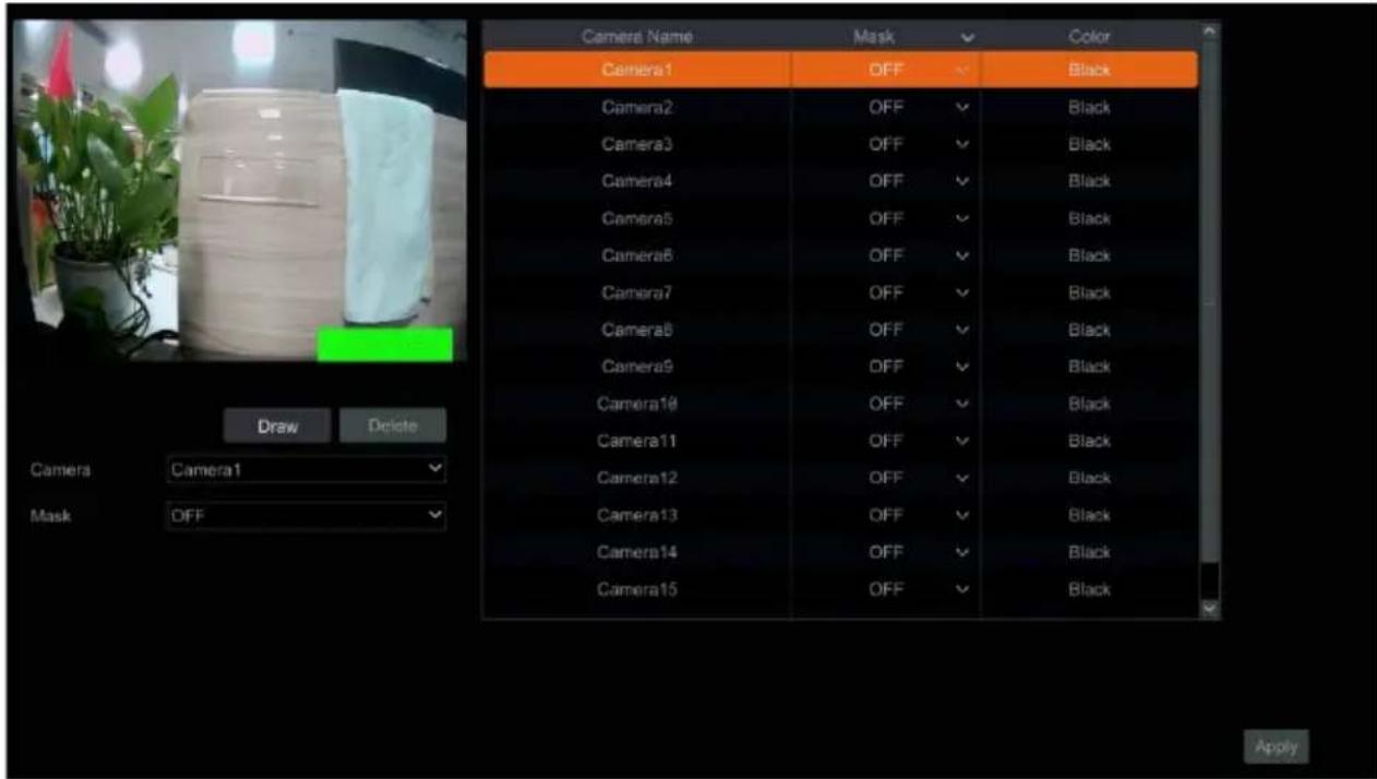
Some areas of the image can be masked for privacy. Up to four mask areas can be set for each camera. Click Start→Settings→Camera→Image→Mask Settings. Select the camera and enable the mask.
Click the "Draw" button then use the mouse in the preview image area to set the mask area.
Click the "Delete" button to delete mask areas.
Click "Apply" to save the settings.
6 PTZ
6.1 PTZ Control Interface Introduction
You can use a virtual controller within the encoder's interface to control IP dome or PTZ cameras.
Click the PTZ Control icon 📁 on the toolbar, at the bottom of the live preview window to go to the PTZ Control interface, as shown below.
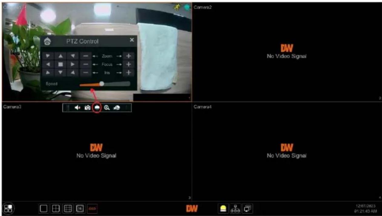
The direction, zoom, focus, iris and movement speed of the camera can be controlled in the small PTZ control window.
6.2 Preset Setting
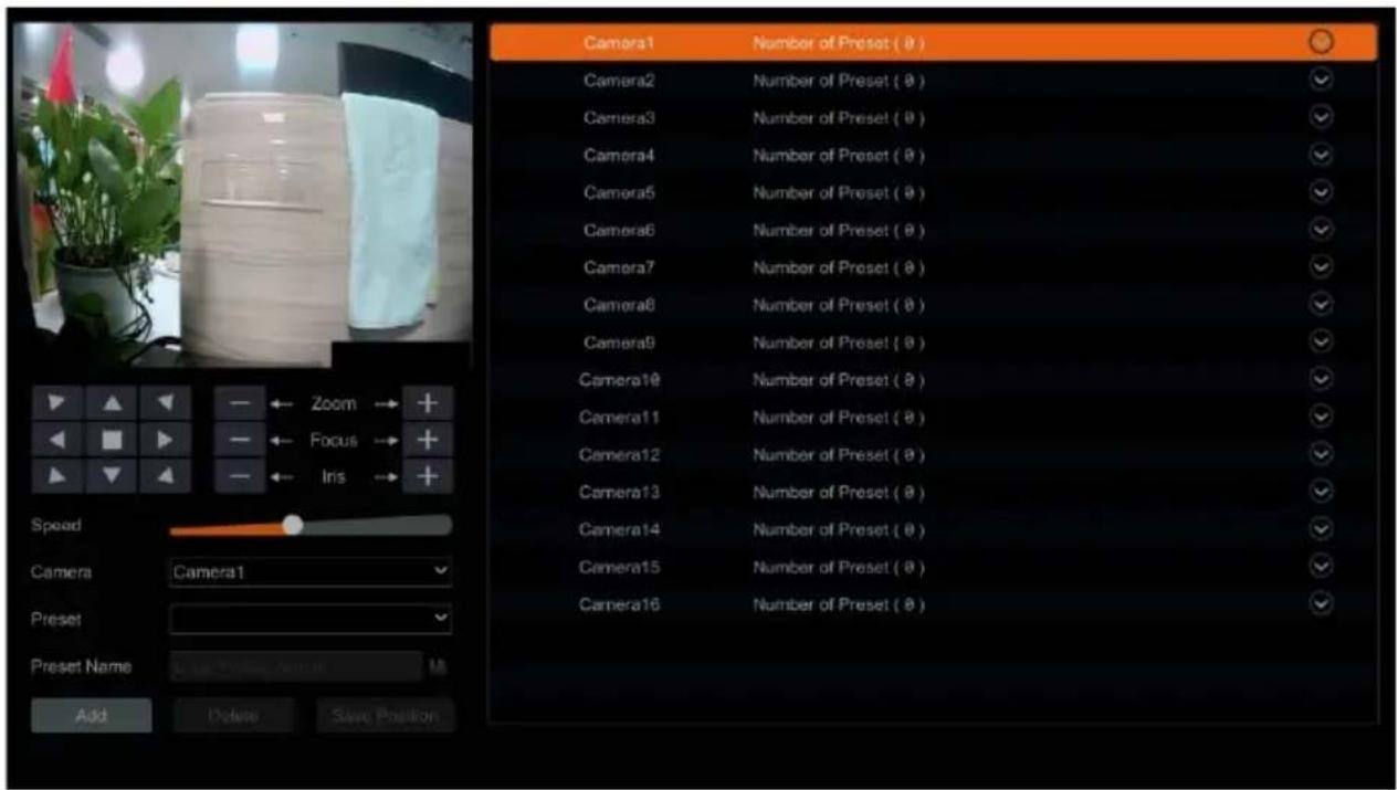
Users can pre-program presets to have PTZ cameras move to predetermined points. Click Start→Settings→Camera→PTZ→Preset to go to the Preset interface as shown below.
- Adding Presets
Select the camera then click the "Add" button to add a new preset.
Alternatively, click √ in the camera list on the right side of the interface to
display the preset information of the dome, then click + to add a preset. The operations of the "Add Preset" window are like that of the PTZ control interface.
- Editing presets
Select the camera and preset. You can enter the new name of the preset, then click the save button to save the new preset name. Adjust the rotation move speed, position, zoom, focus and iris of the preset, then click "Save Position" to save the preset.
- Deleting presets
Select the camera and preset, then click "Delete" to delete the selected preset.
6.3 PTZ Protocol Setting
To control PTZ cameras, the correct protocol must be assigned to the assigned camera channel of the encoder.
Click Start→Settings→Camera→PTZ→Protocol to go to the PTZ Protocol Settings interface as shown below. You can turn the PTZ function ON or OFF, set the control protocol, baud rate and address of the camera in the interface.
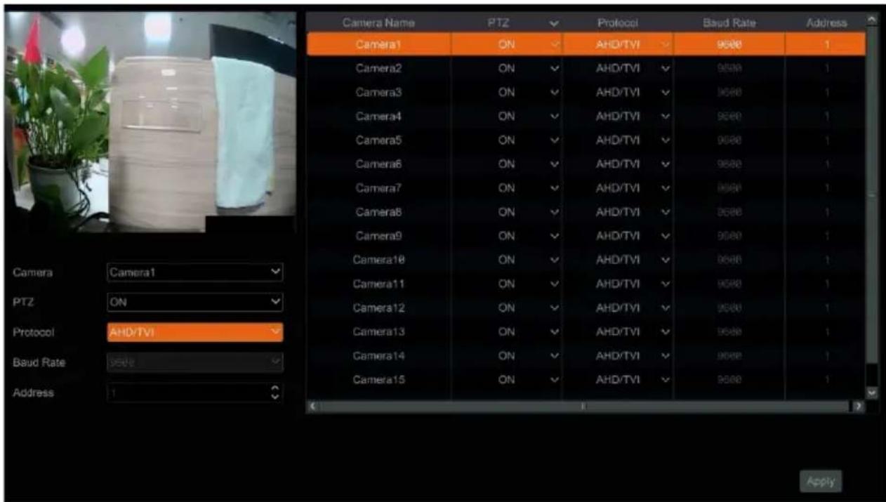
To adjust the PTZ protocol settings, select a camera and enable the PTZ function. Set the protocol, baud rate, and address of the camera according to the camera setting requirements.
- Protocol: The default communication protocol of the encoder is HD-Analog/HD-TVI; ranges from: PELCO-C, PELCO-D, PELCO-P. The protocol setting within the camera must match the protocol that is set in the encoder's settings.
- Address: The address of the PTZ device/camera must be unique. You cannot have more than one PTZ camera assigned to the same address within the PTZ Protocol Settings. This is so that the encoder can discern between its connected devices when sending outgoing PTZ commands.
- Baud Rate: Baud rate of the PTZ device. Range from: 110, 300, 600, 1200, 2400, 4800, 9600, 19200, 34800, 57600, 115200, 230400, 460800, 921600. The baud rate setting within the camera should match the baud rate that is set in the encoder's settings.
7 Event Management
7.1 Sensor Alarm
To complete all the sensor alarm settings, enable the sensor alarm and set up the alarm handling of each camera.
- Click Start→Settings→Event→Sensor Alarm to go to the following interface.
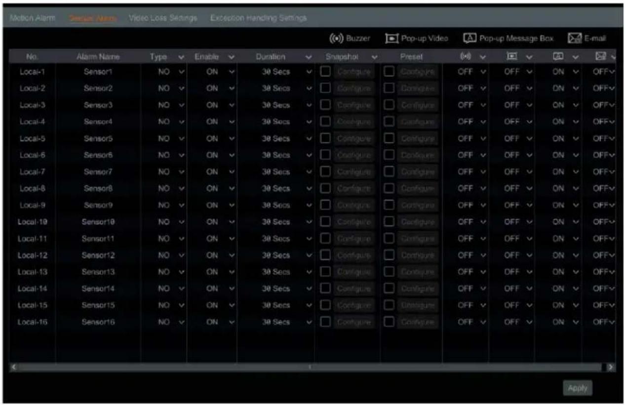
- Select the alarm type (NO or NC) according to the trigger type of the sensor.
• NO = Normally Open circuit
• NC = Normally Closed circuit
-
Enable the sensor alarm of each camera.
-
Check the "Snapshot" and "Preset" and turn ON or OFF "Buzzer", "Popup Video", "Popup Message Box", and "E-mail" sensor options as needed.
-
Click "Apply" to save the settings.
The configuration steps of the alarm mentioned above are as follows:
- Duration: refers to the interval time between adjacent motion detections. For instance, if the duration time is set to 10 seconds, once the system detects motion, it will activate the alarm and will not detect any other motion (specific to the camera) for 10 seconds. If there is another motion event detected during this period, it will be considered a continuation of the previous trigger; otherwise, it will be considered as a new motion event.
- Snapshot: when enabled, the "Trigger Snapshot" window will pop up automatically. Configure the trigger camera in the window. The selected cameras will automatically take a still image when the sensor alarm is triggered.
- Preset: when enabled, the "Trigger Preset" window will pop up automatically. Configure the trigger preset of each camera (see Section 6.2 Preset Setting for details).
- Buzzer: if enabled, the system will begin to emit an audible buzz when the sensor alarm is triggered. To set the delay time of the buzzer (see Section 7.5.3 Buzzer for details).
- Popup Video: if enabled, the system will pop up a corresponding video when the sensor alarm is triggered. To set the duration time of the video (see Section 7.5.2 Display for details).
- Popup Message Box: if enabled, the system will pop up a corresponding alarm message box when the sensor alarm is triggered. To set the duration time of the message box, please see Section 7.5.2 Display for details.
- E-mail: if enabled, the system will send an e-mail when the sensor alarm is triggered. Before you enable the e-mail, please configure the recipient's e-mail address first (see Section 9.1.4 E-mail Configuration for details).
7.2 Motion Alarm
Motion Alarm: when a moving object appears in the motion detection area, a motion alarm will be triggered. It is recommended to enable the motion settings of each camera channel first then set the alarm handling settings to complete the whole configuration of the motion alarm.
7.2.1 Motion Configuration
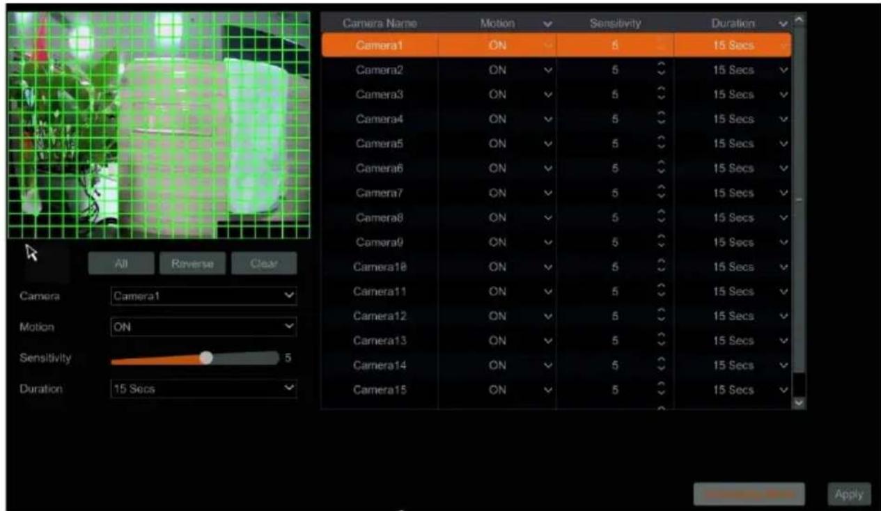
- Click Start→Settings→Camera→Motion to go to the following interface.
-
Select the camera and enable the motion setting, then set the sensitivity and duration settings of the camera.
-
Sensitivity: the higher the value is, the more sensitive it is to detecting motion. You should adjust the value according to the practical conditions since the sensitivity is influenced by color and time (day or night).
-
Duration refers to the interval time between the adjacent motion detections. For instance, if the duration time is set to 10 seconds, once the system detects motion, any other motion (specific to the camera) will not be detected within those 10 seconds. If there is another motion event detected during this period, it will be considered as continuous movement.
-
Click-and-drag within the camera preview image to set the motion area. Highlighted regions are the designated areas of the camera's POV that will watch for motion. Click "All" to set the whole camera image as the motion area. Click "Reverse" to swap the motion areas and the non-detection areas. Click "Clear" to clear all motion areas.
-
Click "Apply" to save the settings. Click "Processing Mode" to go to the alarm handling configuration interface of the motion alarm.
7.2.2 Motion Alarm Handling Configuration
- Click Start→Settings→Event→Motion Alarm.
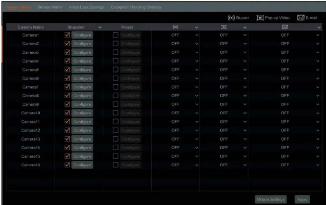
- Enable "Snapshot," "Preset," "Buzzer," "Popup Video," and "E-mail" ON or OFF, according to your needs.
- Snapshot: when enabled, the "Trigger Snapshot" window will pop up automatically. Configure the trigger camera in the window. The selected cameras will automatically take a still image when the motion alarm is triggered.
- Preset: when enabled, the "Trigger Preset" window will pop up automatically. Configure the trigger preset of each camera (see Section 6.2 Preset Setting for details).
- Buzzer: if enabled, the system will begin to emit an audible buzz when the motion alarm is triggered. To set the delay time of the buzzer (see Section 7.5.3 Buzzer for details).
- Popup Video: if enabled, the system will pop up a corresponding video when the motion alarm is triggered. To set the duration time of the video (see Section 7.5.2 Display for details).
- E-mail: if enabled, the system will send an e-mail when the motion alarm is triggered. Before you enable the e-mail, please configure the recipient's e-mail address first (see Section 9.1.4 E-mail Configuration for details).
- Click "Apply" to save the settings. You can click "Motion Settings" to go to the motion configuration interface.
7.3 Video Loss Settings
- Click Start→Settings→Event→Video Loss Settings.
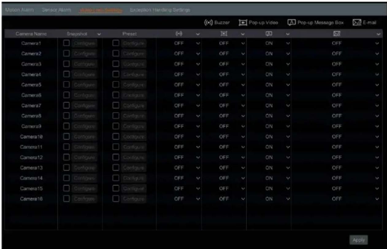
- Enable "Snapshot," "Preset," "Buzzer," "Popup Video," "Popup Message Box," and "E-mail" ON or OFF, according to your needs.
- Snapshot: when enabled, the "Trigger Snapshot" window will pop up automatically. Configure the trigger camera in the window. The selected cameras will automatically take a still image when video loss is detected.
- Buzzer: if enabled, the system will begin to emit an audible buzz when video loss is detected. To set the delay time of the buzzer (see Section 7.5.3 Buzzer for details).
- Popup Video: if enabled, the system will pop up a corresponding video when video loss is detected. To set the duration time of the video (see Section 7.5.2 Display for details).
- Popup Message Box: if enabled, the system will pop up a corresponding alarm message box when video loss is detected. To set the duration time of the message box, please see Section 7.5.2 Display for details.
- E-mail: if enabled, the system will send an e-mail when the sensor alarm is triggered. Before you enable the e-mail, please configure the recipient's e-mail address first (see Section 9.1.4 E-mail Configuration for details).
- Click "Apply" to save the settings.
7.4 Exception Handling Settings
Configure notifications for system events unrelated to external device alarms.
-
Click Start→Settings→Event→Exception Handling Settings.
-
Enable "Buzzer," "Popup Message Box," and "E-mail" ON or OFF, according to your needs. The exception handling settings are similar to that of the sensor alarm (see Section 7.1 Sensor Alarm).
-
IP Address Conflict: an alert will occur for the system if an IP address conflict is detected.
• Network Disconnection: an alert will occur for the system if loss of connection with the local network is detected. -
Click "Apply" to save the settings.

7.5 Alarm Event Notification
7.5.1 E-mail
Click Start→Settings→Event→Event Notification→E-mail to go to the e-mail configuration interface. Set the outgoing e-mail address information of the email notification recipients for event alarms (see Section 9.1.4 E-mail Configuration).
7.5.2 Display
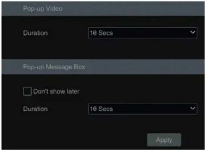
Click Start→Settings→Event→Event Notification→Display to go to the display configuration interface. Set the duration time of the popup video and the popup message box. Click "Apply" to save the settings.
7.5.3 Buzzer
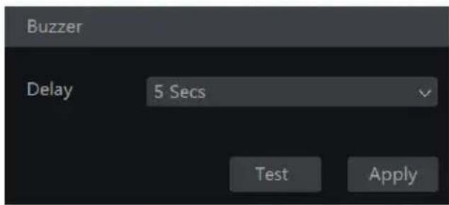
Click Start→Settings→Event→Event Notification→Buzzer to go to the buzzer configuration interface. Set the delay time of the buzzer, then click "Apply" to save the setting. You can click "Test" to test the buzzer.
7.6 View Alarm Status
Click Start→Settings→Alarm→Alarm Status or click 📄 on the toolbar at the bottom of the live view interface to view the alarm status.
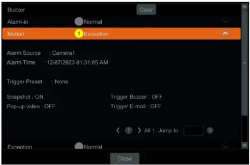
Click the "Clear" button to stop the buzzer when the buzzer alarm occurs. Click to view the detailed information.

If the exception information is more than one page, you can enter the page number in the box, then click ➤ to jump to the specified page. Click ◀ / ➤ to view the exception alarm information on the previous/next page.
8 Account & Permission Management
8.1 Account Management
Add and edit user profiles and set user permissions.
Click Start→Settings→Account and Authority→Account→Edit User.
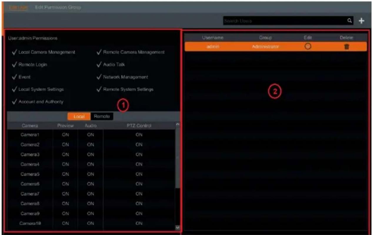
Area ① displays the user permissions settings. Area ② displays the user list. Click on the user in the list to display its user permissions in area ①.
There are three default permission groups ("Administrator," "Advanced," and "Common") available when adding accounts. You can manually add a new permission group (see Section 8.3.1 Add Permission Group for details).
Only the admin and the users that have the "Account and Authority" permission can manage the system's accounts. Group "Administrator" owns all the permissions displayed in area ① except "Account and Authority," and its permissions cannot be changed, while the permissions of "Advanced" and "Common" can be changed.
8.1.1 Add User
- Click Start→Settings→Account and Authority→Account→Add User or click + beside the search box to pop up the Add User window as shown below.
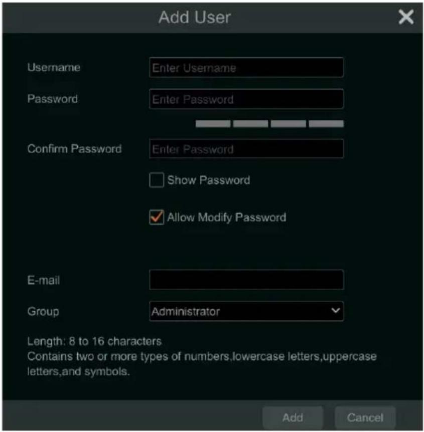
- Set the username, password, user group, and e-mail address. Click "Add" to add the user.
- If the password security level is changed, follow the password tips shown in the interface to set the password. To set the password security level, click Account and Authority→Password Security.
8.1.2 Edit User
Click Start→Settings→Account and Authority→Account→Edit User, then click in the user list or double click on the user to edit the user information.

Click delete the user (the user admin cannot be deleted).
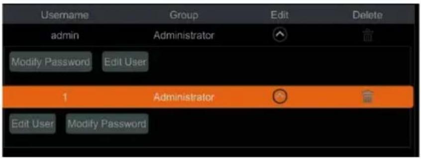
- Modify Password
Click "Modify Password" to pop up a window. Enter the current password, then set a new password. Click "OK" to save the settings.
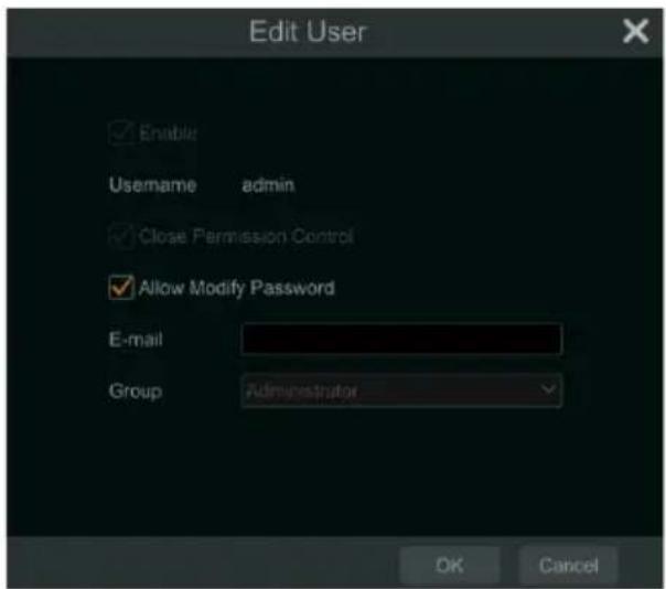
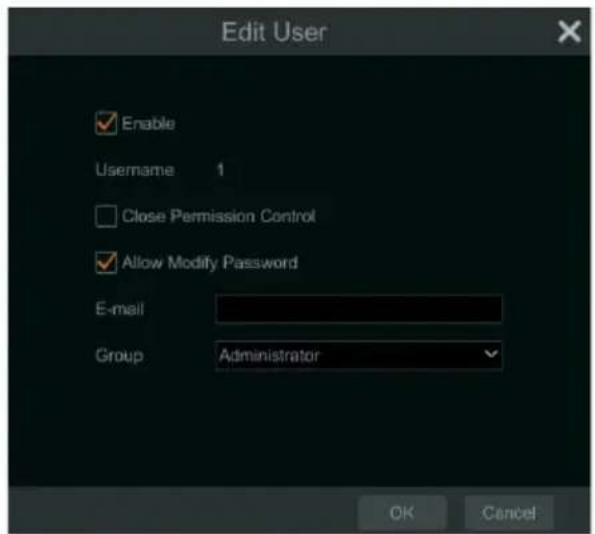
- Edit User
Click "Edit User" to pop up the window as shown below. The admin is always enabled by default, its permission control can never be closed, and the permission group cannot be changed by default.
You can deactivate or activate any other user profiles (if disabled, the user profile cannot be used). If the "Permission Control" setting is closed, the user will have all the permissions that the admin user has. Set permission group as needed (see Section 8.3.1 Add Permission Group for details). Click "OK" to save the settings.
8.2 User Login & Logout
- Login: Click Start→Login or directly click the preview interface), select a username, and enter the password in the popup window. Click the "Login" button to log in to the system.
- Logout: Click Start→Logout or click Start→Shutdown to pop up the "Shutdown" window. Select "Logout" in the window, then click "OK" to log out of the system.
8.3 Permission Management
8.3.1 Add Permission Group
Click Start→Settings→Account and Authority→Account→Edit Permission Group.
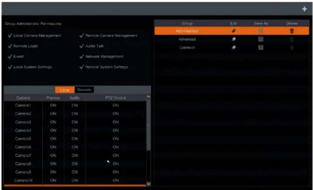
Click + to add a permission group. Set the group name, check the permissions as required, and set the "Local" and "Remote" permissions. Click "Add" to save the settings.
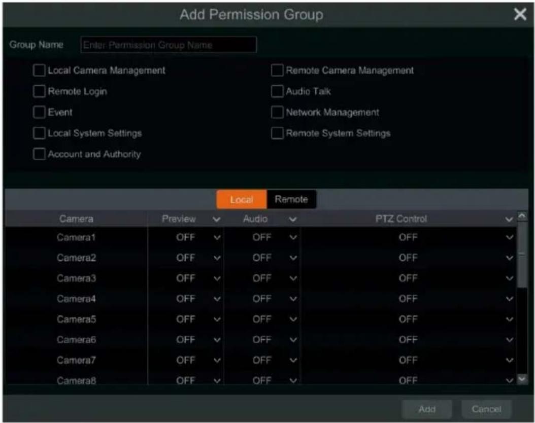
8.3.2 Edit Permission Group
Go to the "Edit Permission Group" interface, then click in the group list to edit the permission group. The operations of the "Edit Permission Group" are similar to that of the "Add Permission Group" setup (see Section 8.3.1 Add Permission Group for details). Click to save the group settings. Click to delete the permission group. The three default permission groups ("Administrator," "Advanced," and "Common") cannot be deleted.
8.4 Block and Allow Lists
- Click Start→Settings→Account, and Authority→Security to go to the following interface.
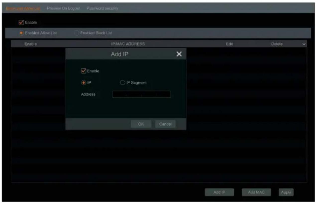
- Check "Enable", then choose "Enable Allow List" or "Enable Block List". The PC client whose IP address is in the allow list can access the encoder remotely while the PC client in the block list cannot.
- Click "Add IP" or "Add MAC" to add an P/IP segment/MAC then check "Enable" in the popup window. Enter the IP/IP segment/MAC, then click "OK". In the
above interface, click 📋 to edit IP/IP segment/MAC, and click 📋 to delete it. Click "Apply" to save the settings.
8.5 Preview On Logout
Click Start→Settings→Account and Authority→Security→Preview On Logout. Select a camera then set the Preview Permission on Logout setting ON or OFF as required. If a camera's preview permission on logout is "ON," you can view the live image of the camera when the system is logged out.
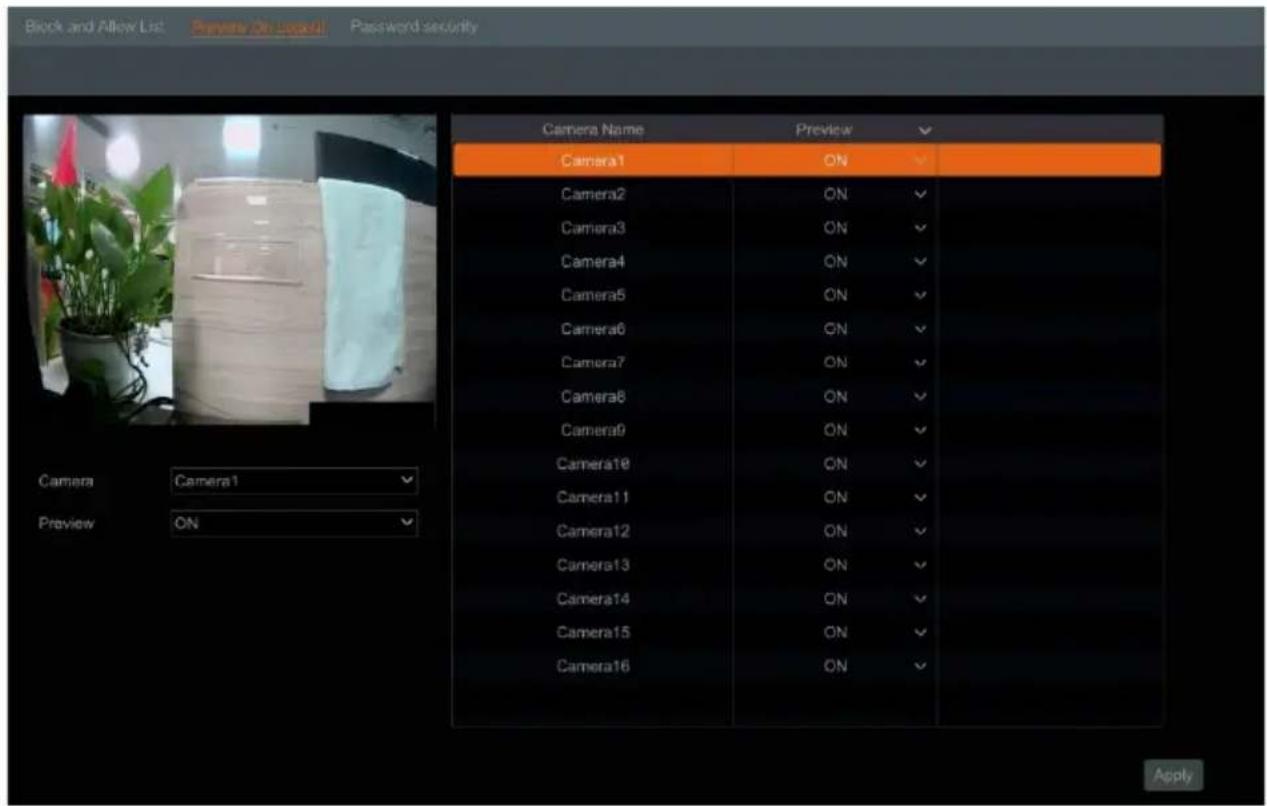
8.6 Password Security
Click Start→Settings→Account and Authority→Security→Password Security.
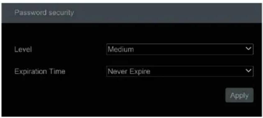
In this interface, you can set the level and expiration time of the user passwords.
Level: 3 levels—Medium, Strong, or Stronger.
Expiration Time: 4 options --Never expire, 30 days, 90 days or 180.
8.7 View Online User
Click Start→Settings→Account and Authority→User Status to view the online user information. You can view the online username, login type, IP address and login time.
Click 📄 to pop up a window showing the preview occupied channel number.
9 Device Management
9.1 Network Configuration
9.1.1 TCP/IP Configuration
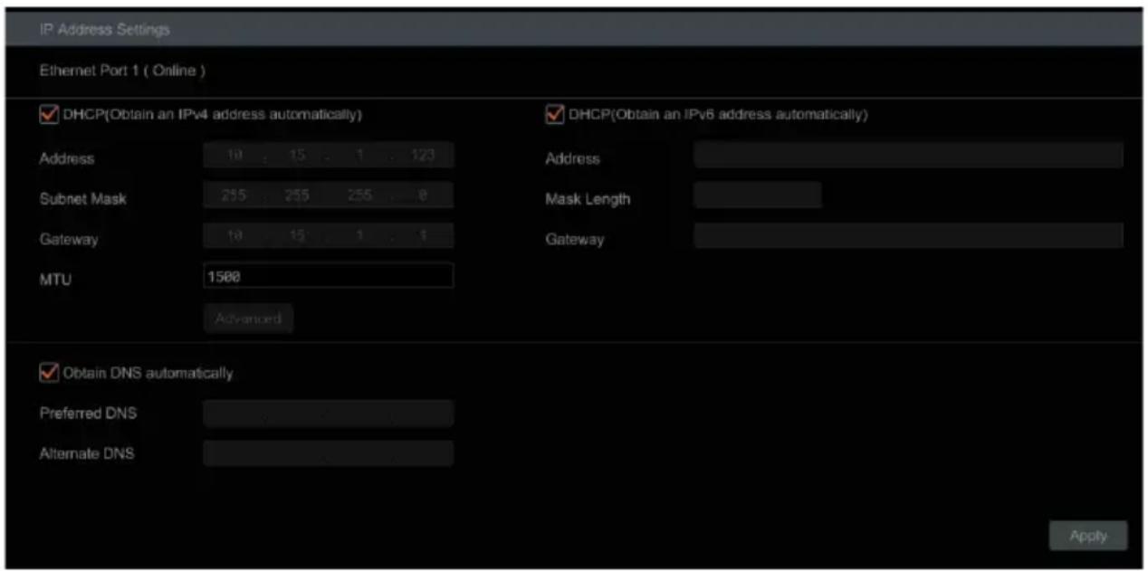
Click Start→Settings→Network→TCP/IP. Check "Obtain an IPv4 address automatically", "Obtain an IPv6 address automatically," and "Obtain DNS automatically" to have the system acquire network addresses automatically.
Alternatively, manually enter the network addresses.
Modify the MTU (Maximum Transmission Unit) value according to the network condition for higher network transmission efficiency. Click "Apply" to save the settings.
9.1.2 Port Configuration
Click Start→Settings→Network→Port. Enter the HTTP port of the encoder and click "Apply" to save the settings. You can also enable and set the RTSP port as needed (check "Anonymous" as required).
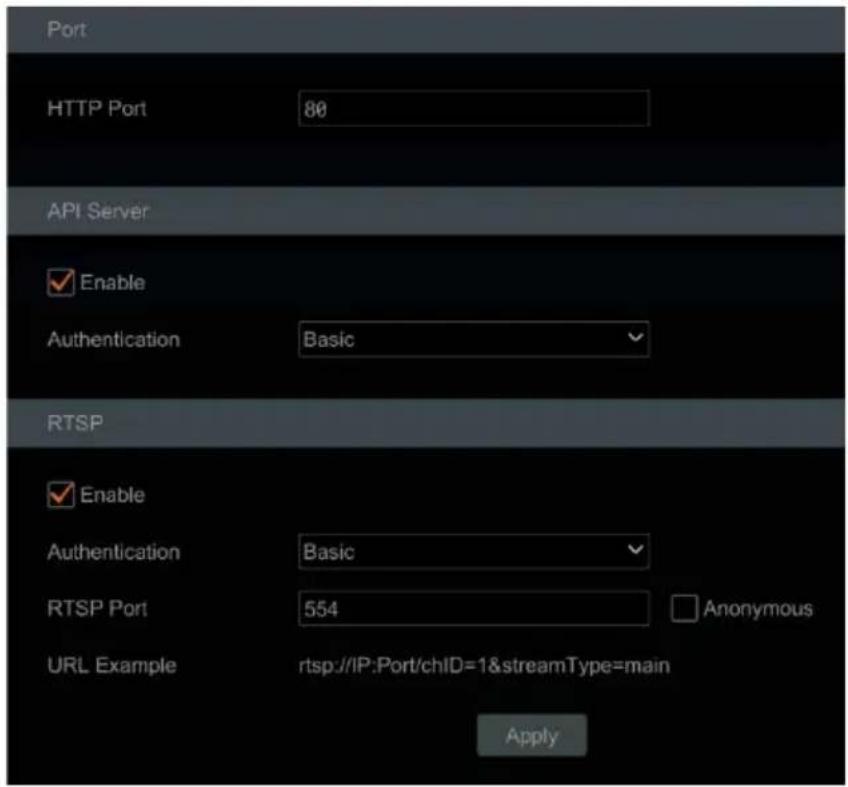
- HTTP Port: the default HTTP port of the encoder is 80 but can be changed as needed. The port is mainly used for web client access. If you want to access the encoder through a web browser, enter the IP address and HTTP port in the address bar of the web browser. For example, http://192.168.11.61:81.
**NOTE: The HTTP port and server port of the encoder should be mapped (port forwarded) on the local router before the encoder can be accessed via WAN.
- Authentication: Basic authentication and digest authentication are optional. “Basic authentication” will send credentials using clear text while “Digest Authentication” will send credentials using MD5 hashing while connecting via web browser.
- RTSP Port: RTSP (real-time stream protocol) can be used to control the sending of real-time data. By using a media player (like VLC player) that supports RTSP, you can view live images synchronously.
• The default RTSP port is 554.
o Main Stream: rtsp://IP address:554/chID=1&streamType=main
Sub-stream: rtsp://IP address:554/chID=1&streamType=sub;
- “chID” indicates the channel ID of the encoder. For example, “chID=1 is for channel 1 of the encoder.
- URL Example: Enable RTSP and "Anonymous." Enter the listed example into a media player's network address bar to view the RTSP stream.
9.1.3 DDNS Configuration
The DDNS is used to control the dynamic IP address through a domain name. You can access the encoder easily if the DDNS setting is enabled and configured.
Click Start→Settings→Network→DDNS.
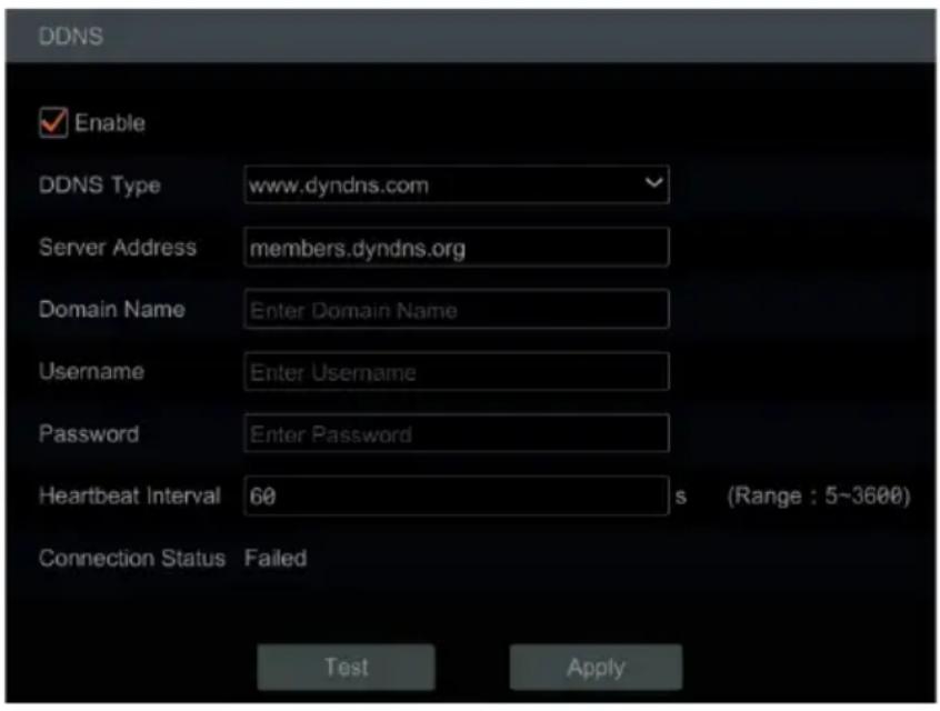
Check "Enable" and select the DDNS type.
Enter the server address, domain name, username and password according to the selected DDNS type then click "Test" to test the effectiveness of the input information.
Click "Apply" to save the settings.
**NOTE: The "Hearbeat Interval" setting can only be configured if the DDNS type is set as "dyndns".
You will have to enter the server address and domain name if some DDNS types are selected. Go to the relative DNS website to register a domain name and enter the registered domain information to the encoder.
For example, if the domain name is registered to www.Encoderdydns.com:
- Use a web browser to visit the DNS website (for example, www.Encoderdydns.com).
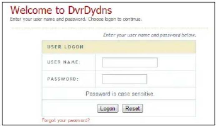
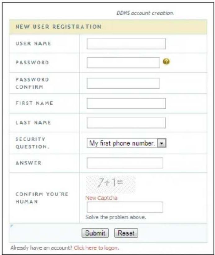
- Click "Registration". Set the DDNS account information (username, password and so on), then click Submit to save the account.
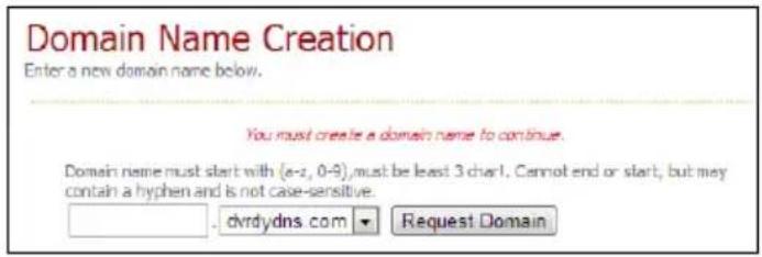
- Create a domain name, then click Request Domain.
- After you successfully request your domain name, you will see your domain name information in the list.
![My Domains Your domain names are listed below. Choose create new domain to add additional domain names. Your domain was successfully created. Search by Domain. Search Click a name to edit your domain settings. NAME STATUS DOMAIN RED SUNSHINE redsunshine.dvrdydns.com Last Update: Not yet updated IP Address: 210.21.229.138 Create additional domain names [1]](/content/2026/05/944199/images/37bab83d5815734e9f4cd4ef496a5d0e30215d826f657ca93750bd975ca7f0a8.jpg)
- After acquiring the domain information from the DNS service's website, go to the encoder and navigate Start→Settings→Network→DDNS to go to the DDNS setting menu. Enable DDNS and select the "www.Encoderdydns.com" DDNS type. Enter the registered username, password, and domain name then click "Apply".
- Map the IP address and HTTP port in the router (you can skip this step if the UPnP function is enabled).
- Once the DDNS has been established with the encoder, you can enter the registered domain name and HTTP port. For example, http://www.xxx.Encoderdydns.com:81 in the address bar, then press the Enter key to go to the web client.
9.1.4 E-mail Configuration
To have the encoder send notifications, an outgoing email must be established. Configure the outgoing email by navigating to Start→Settings→Network→E-mail.
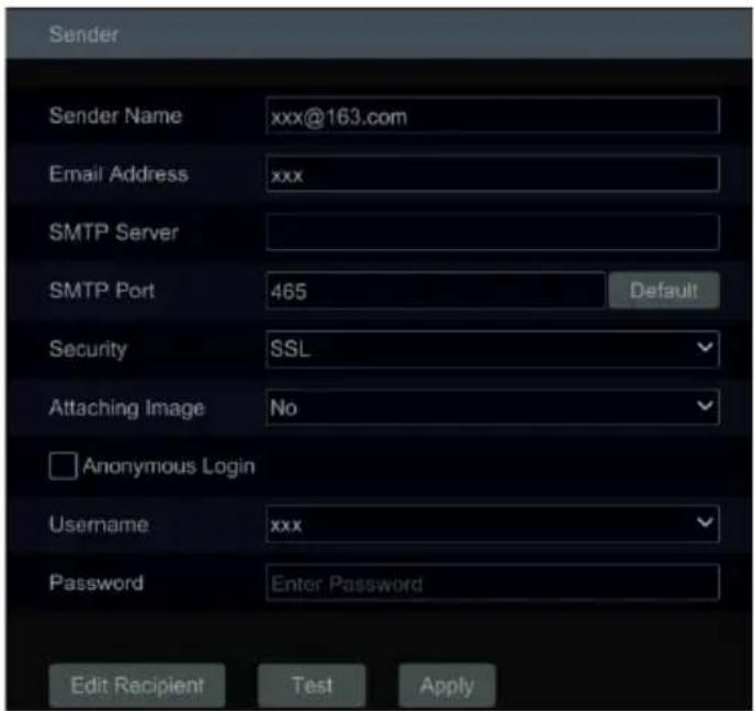
- Configure the following settings:
- Sender Name: enter the outgoing email address that will be used for the setup.
- Email Address: re-enter the outgoing email address that will be used for the setup.
- SMTP Server: enter the SMTP server that is providing the email service. For example, if using a Gmail account, the SMTP server would be "smtp.gmail.com".
- SMTP Port: enter the service port of the SMTP server. For example, if using a Gmail account, the SMTP port would be "587". You can click the Default button to reset the port to the default value.
- Security: select the type of security authentication that is used for the SMTP server. For example, if using a Gmail account, the service uses SSL and StartTLS.
- Attaching Image: select whether to include an image attachment when sending email notifications.
- Anonymous Login: you do not need to enter a username and password if this setting is enabled.
- Username: enter the username that is used to log into the outgoing email service or the outgoing email address itself. The username list will be updated automatically according to the e-mail address that is entered.
- Password: enter the password that is used to log into the outgoing email service.
-
After configuring the Sender settings, click "Apply" to save the settings.
-
Click "Test" to pop up a window. Enter the e-mail address of the test recipient in the window, then click the "OK" button. The sender's e-mail address will send an e-mail to the recipient. If the e-mail is sent successfully, it indicates that the e-mail address of the sender is configured correctly.
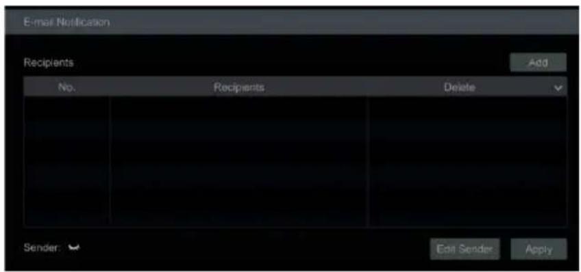
To configure the list of recipients that will receive the email notifications, click "Edit Recipient" to go to the following interface.
-
Click "Add" and enter the recipient's e-mail address.
-
Click to delete the recipient in the list.
-
Click "Apply" to save the settings.
-
Click "Edit Sender" to go to the sender's e-mail configuration interface.
9.1.5 UPnP Configuration
By UPnP, you can access the encoder through the web client, using WAN via an external router without port mapping.
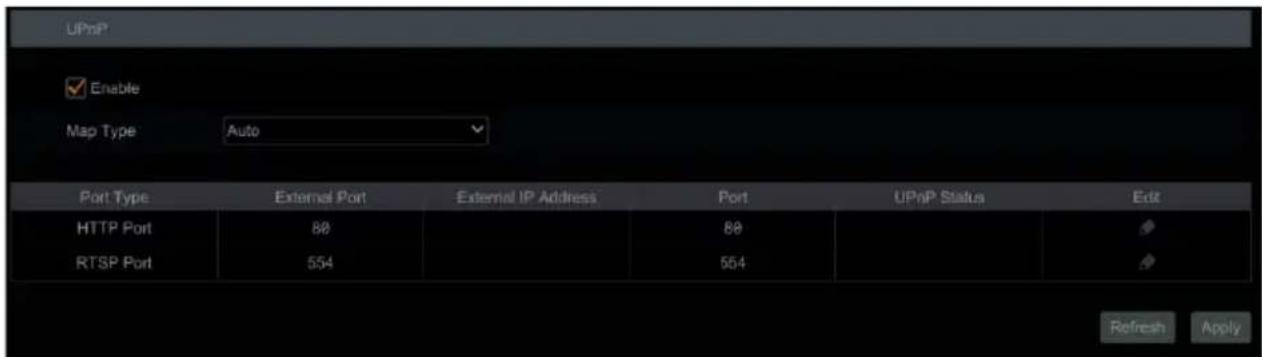
- Click Start→Settings→Network→UPnPto go to the following interface.
- Make sure the router supports the UPnP function and the UPnP is enabled in the router.
- Set the encoder's IP address, subnet mask, gateway, etc. corresponding to the router.
- Check "Enable" in the interface as shown below, then click "Apply."
Click "Refresh" to refresh the UPnP status. If the UPnP status were still "Invalid UPnP" after refreshing it many times, the port number would be wrong. Please change the mapping type to "Manual", then click 🔒 to modify the port until the UPnP status turns to "Valid UPnP." Refer to the following picture. You can view the encoder's
external IP address. Enter the external IP address plus port in the address bar to access the encoder, such as http://183.17.254.19:81.
9.1.6 802.1X
If enabled, the encoder data can be protected. When the encoder is connected to the network protected by the IEEE 802.1X, user authentication is needed.
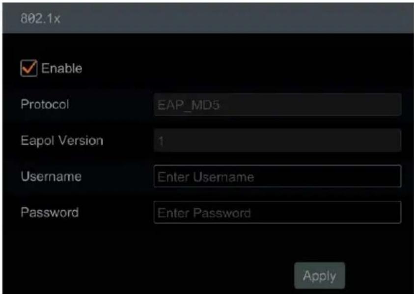
To use this function, the encoder must be connected to a switch supporting the 802.1x protocol. The switch can be considered as an authentication system to identify the device in a local network. If the encoder connected to the network interface of the switch has passed the authentication of the switch, it can be accessed via the local network.
• Protocol: Use the default settings.
• EAPOL Version: Use the default settings.
- Username and Password: The username and password must be the same as the username and password applied for and registered in the authentication server.
9.1.7 FTP Configuration
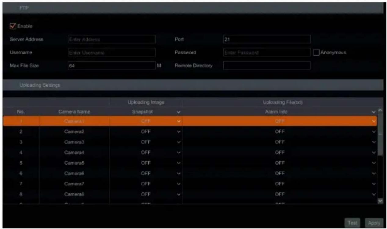
To configure the file transfer protocol (FTP) settings of the encoder, click Start→Settings→Network→FTP to go to the interface for FTP configuration.
Check "Enable" and enter the server's name, port, username and password, max file size and remote directory.
After that, you can choose the images and alarm information to upload as needed in this interface.
9.1.8 SNMP
Before setting the SNMP, please download the SNMP software to receive and manage device information via the SNMP port. By setting the trap address, the device is allowed to send the alarm event and exception message to the monitoring center.
- Click Start→Settings→Network→SNMPto go to the interface for SNMP configuration.
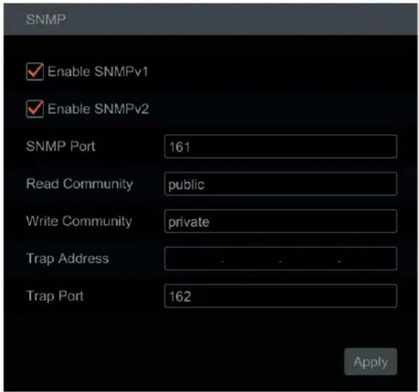
- Check SNMPv1 or SNMPv2 to enable this function.
- Set the port of the SNMP.
- Set the trap address and the trap port.
- Click "Apply" to save the settings.
Trap Address: The IP address of the SNMP host.
Trap Port: The port of the SNMP host.
9.1.9 ONVIF
The encoder supports ONVIF (Profile G/T/S) and can be searched for on ONVIF's official website. After ONVIF is enabled, it can be searched and connected to the third-party platform via the ONVIF protocol.
Click Start→Settings→Network→Integration→ONVIF to enter the following interface.
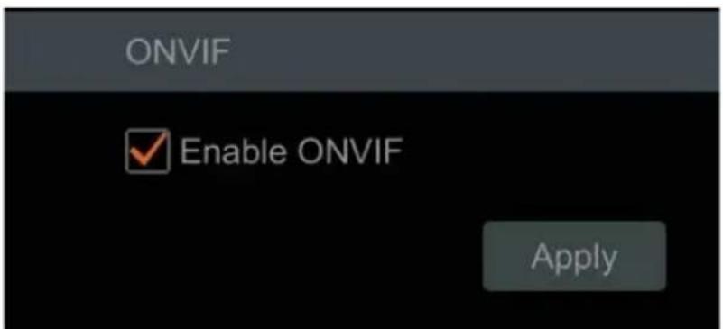
**NOTE: when adding the device to the third-party platform with ONVIF protocol, please check "Enable ONVIF" first in the above interface.
9.1.10 View Network Status
Click Start→Settings→Network→Network Status to view the encoder's network status or click 📋 on the toolbar at the bottom of the live view interface to view the network status conveniently.
9.2 Basic Configuration
9.2.1 Common Configuration
Click Start→Settings→System→Basic→General Settings.
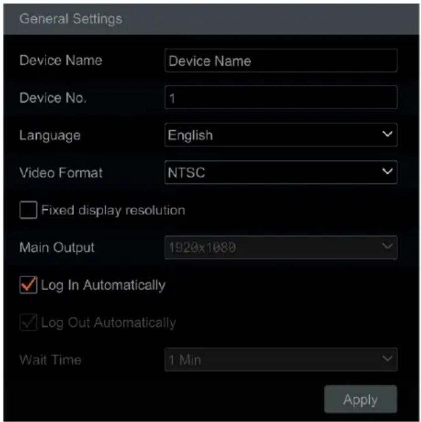
Set the device name, device No., language, video format and main output resolution. "Log In Automatically" and "Log Out Automatically" (if checked, you can set the wait time). Click "Apply" to save the settings.
- Device Name: The name of the device. It may be displayed on the client end or CMS to help the user recognize the device remotely.
- Video Format: Two modes: PAL and NTSC. Select the video format according to the camera.
9.2.2 Date and Time Configuration
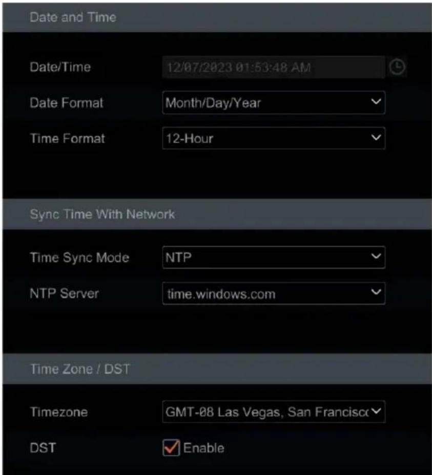
Click Start→Settings→System→Basic→Date and Time.
Set the system time, date format, time format and time zone of the encoder.
The default time zone is GMT-08. If the selected time zone includes DST, the DST of the time zone will be checked by default. Click "Apply" to save the settings.
You can manually set the system time or synchronize the system time with the network through NTP.
- Manual: select "Manual" in the "Time Sync Mode" option, then click 📋 after the "System Time" option to set the system time.
- NTP: select "NTP" in the "Synchronous" option, then choose the NTP server.
9.3 Factory Default
Click Start→Settings→System→Maintenance→Factory Default. Choose the function as needed.
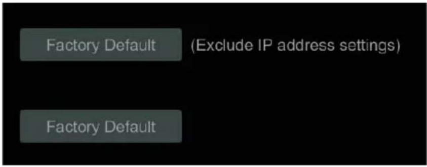
**NOTE: Resetting to the factory default settings will not change the time zone.
9.4 Device Software Upgrade
You can click Start→Settings→System→Information→Basic to view MCU, kernel version, firmware version etc. Before upgrading, upgrade file from your dealer.
The upgrade steps are as follows:
- Copy the upgrade software onto a USB storage device.
- Insert the USB storage device into the USB interface of the encoder.
- Click Start→Settings→System→Maintenance→Upgrade to go to the "Upgrade" interface. Select the USB device in the "Device Name" option and navigate to the upgrade software. Select the upgrade software then click "Upgrade."
- The system may automatically restart during upgrading. Please wait for the upgrade to complete and do not power off the encoder during this process.
**NOTE: The file system of the USB mobile device which is used for upgrading, backing up and restoring should be in FAT32 format.
9.5 Backup and Restore
You can back up the configuration file of the encoder by exporting the configuration file to other storage devices. You can also import the configuration file to other encoders that are the same model to save time.
To use the Backup and Recover functions, insert the USB storage device into the USB interface of the encoder then click Start→Settings→System→Maintenance→Backup and Restore to go to the interface.
- Backup
Compressor™
Select the USB device in the "Device Name" option and go to the path where you want to store the configuration backup file. Click the "Backup" button then click the "OK" button in the popup window.
- Recover
Select the USB device in the "Device Name" option and find the configuration backup file. Click the "Recover" button then click the "OK" button in the popup window.
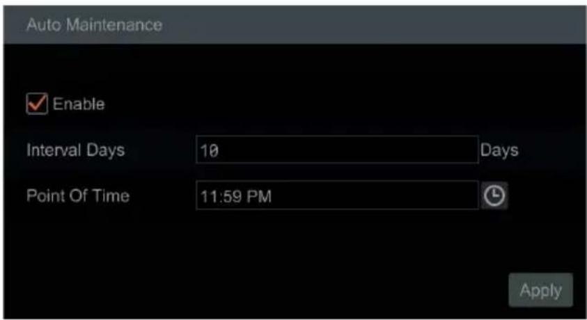
9.6 Restart Automatically
You can set the automatic restart time for the encoder to automatically restart as part of regular maintenance.
Click Start→Settings→System→Maintenance→Auto Maintenance.
Enable the auto maintenance, set the number of interval days and point of time for how frequently and when to restart, then click "Apply" to save the settings. The encoder will restart automatically at the pointed time every few days.
9.7 View Log
Administrators can view and export system logs from the View Log menu.
Click Start→Settings→System→Maintenance→View Log to go to the log view interface. Select the log main type, click 📊 to set the start time and end time, then click the "Search" button. The searched log files will be displayed in the list.
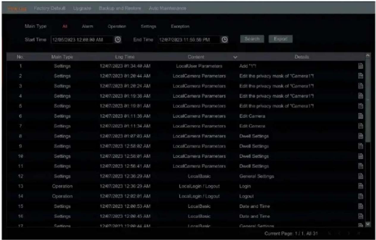
Choose the log file in the list, then click the "Export" button to export the log file. Click ▼ on the "Content" title bar to pop up a menu list. You can select the contents in the menu list to filter what will show in the log list.
9.8 View System Information
Click Start→Settings→System→Information then click the corresponding menu to view the "Basic," "Camera Status," and "Alarm Status" information of the system.
10 Remote Surveillance
10.1 Web LAN Access
- Click Start→Settings→Network→TCP/IP to go to the "TCP/IP" interface. Set the IP address, subnet mask, gateway, preferred DNS and alternate DNS of the encoder.
- Open a web browser on your computer and enter the IP address of the encoder in the address bar to go to the login interface as shown below. You can change the display language on the top right corner of the login interface. Enter the username and password of the encoder in the interface then click "Login" to go to the live view interface.
10.2 Web WAN Access
- Router Access
- Click Start→Settings→Network→TCP/IP to go to the "TCP/IP" interface. Set the IP address, subnet mask, gateway, preferred DNS and alternate DNS of the encoder.
- Set the HTTP port (it is suggested to modify the HTTP port because the default HTTP port 80 might already be in use) and enable the UPnP
function in both the encoder and in the router. If the UPnP function is not available in the router, you need to manually forward the LAN IP address, HTTP port and server port of the encoder in the router. Port mapping settings may vary in different routers, so please refer to the router's user manual for details.
- Get the WAN IP address of the encoder from the router. Open a web browser on your computer, enter the WAN IP address and HTTP port (ex. http://116.30.18.215:100) in the address bar to go to the login interface. Enter the username and password of the encoder in the interface, then click "Login" to go to the live view interface.
**NOTE: If the WAN IP address is a dynamic IP address, it is necessary for you to use the domain name to access the encoder. Click Start→Settings→Network→DDNS to set DDNS (see 13.1.4 DDNS Configuration for details). By using DDNS function you can use the domain name plus HTTP port like http://sunshine.Encoderdydns.com:100 to access the encoder via internet.
10.3 Web Remote Control
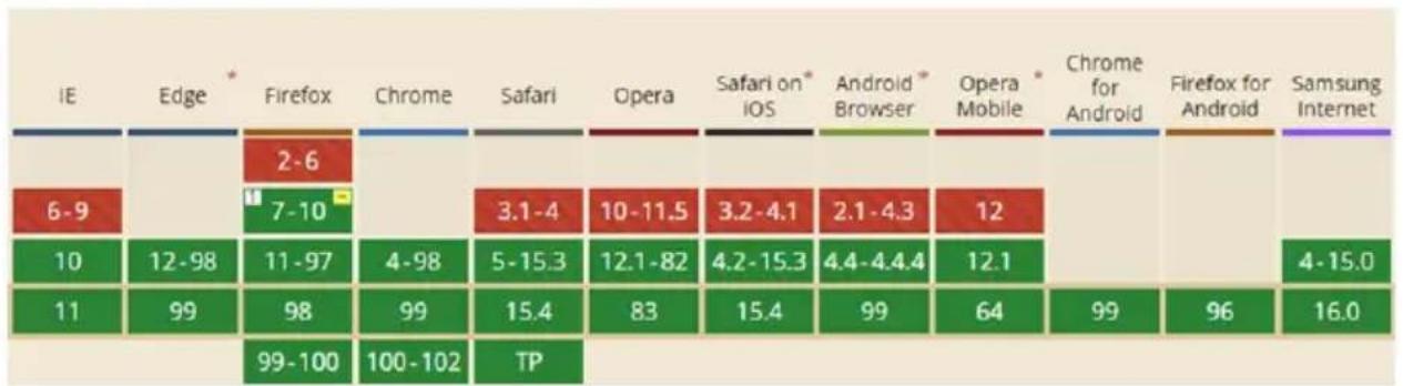
The encoder supports web client access with or without a plug-in.
The supported browsers (green color) for remote access with the plug-in are as follows. The red color versions are not supported.
other
| IE | Edge | Firefox | Chrome | Safari | Opera | Safari on iOS | Android Browser | Opera Mobile | Chrome for Android | Firefox for Android | Samsung Internet | |---|---|---|---|---|---|---|---|---|---|---|---| | 6-9 | 12-98 | 7-10 | 3.1-4 | 10-11.5 | 3.2-4.1 | 2.1-4.3 | 12 | 10 | 12 | 12 | 4-15.0 | | 10 | 99 | 11-97 | 4-98 | 5-15.3 | 12.1-82 | 4.2-15.3 | 4.4-4.4.4 | 12.1 | 12.1 | 12.1 | 4-15.0 | | 11 | 99 | 98 | 99 | 15.4 | 83 | 15.4 | 99 | 64 | 64 | 99 | 16.0 | | 99-100 | 99-100 | 100-102 | TP | 15.4 | 83 | 15.4 | 99 | 64 | 64 | 99 | 16.0 | The chart displays a single value for IE at 2-6 and is also labeled with an asterisk '2-6'. The color intensity likely represents the magnitude of the measured variable.When you access the encoder through the web browser for the first time, the browser will need to download and install the relative components for normal preview and playback.
If permission for the configuration modification is needed after the plug-in runs, please allow it, or the interface cannot be displayed normally; if the relevant ports of plug-in (port 11563; port 12863; port 13863) are occupied, the system will tell you which program has occupied the port. Please stop the occupied program.
The supported browsers (green color) for remote access without the plug-in are as follows. The red color versions are not supported.
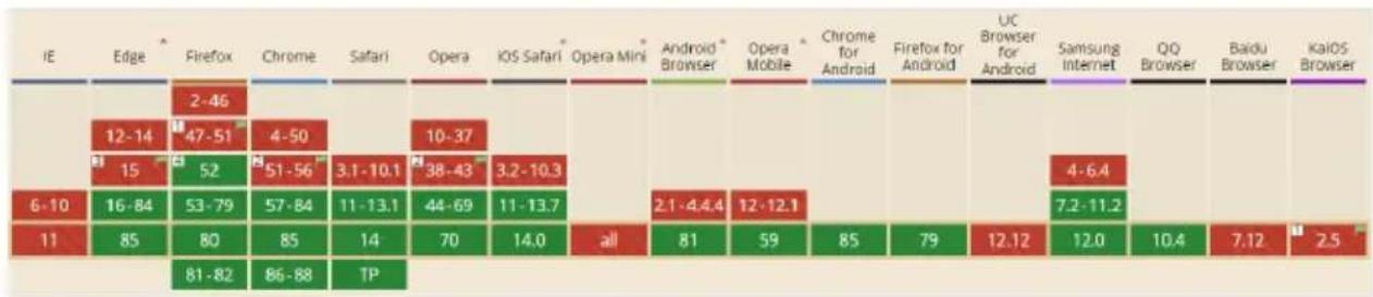
Please refer to the tips in the remote interfaces for details. The buttons and icons on the top right corner of the remote interface are introduced as follows.
• Admin: the current login username.
- Logout: click to log out and return to the login interface.
- Modify Password: click to change the password of the current login user. Enter the current password, then set a new password in the popup window. Click "OK" to save the new password.
10.3.1 Remote Preview
Click "Live Display" in the remote interface to go to the viewing interface.
Plug-in Free Live View
When not using a plugin, only a 4-screen display can be supported for the web client. However, the web client functions are the same.
Plug-in Required Live View
The live viewing interface consists of the four areas marked in the following picture.
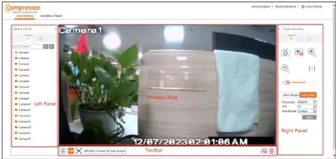
- Start Preview
Select a window in the viewing area, then click on the online camera on the left panel to view the camera in the window. You can click 📋 in the toolbar to preview all the cameras.
- Left Panel Introduction
Click < on the left panel to hide the panel and click > to display the panel. You can view all the added cameras and groups on the left panel.

: Click to view the camera list.

: Click to view customized display mode.
Enter the camera name in the search box, then click 🔒 to search the camera. Click 🔒 to refresh the camera list.
• Tool Bar Introduction
| Button | Meaning | |
 | Screen mode button. | |
 | Click to disable OSD. Click it again to enable OSD. | |
| [D48S] | Click to show the full screen. Right-click on the full screen to exit the full screen. | |
 | Click "All Main Stream" or "All Sub Stream" to set the stream of all the cameras. | |
 | Click to preview all the cameras. | |
 | Click to close all the preview cameras. | |
 | Click to enable talk with the encoder. | |
• Right Panel Introduction
Click 📋 on the right panel to go to the "PTZ" panel. Click 📋 to go to the "Operation" panel.
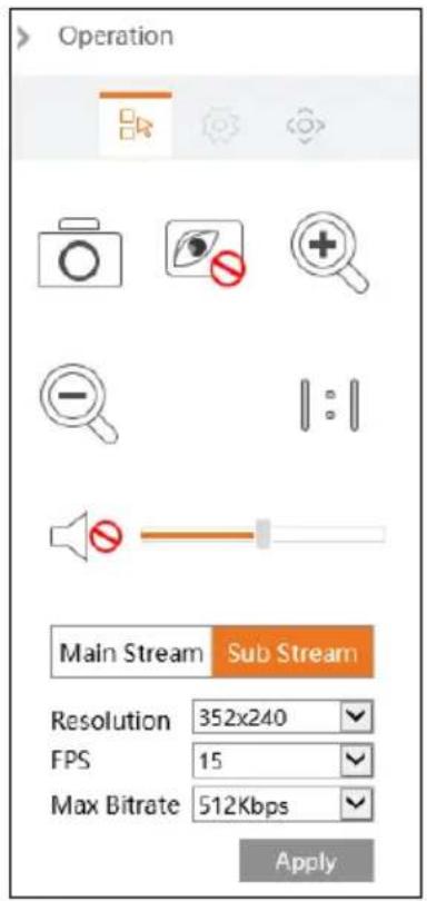
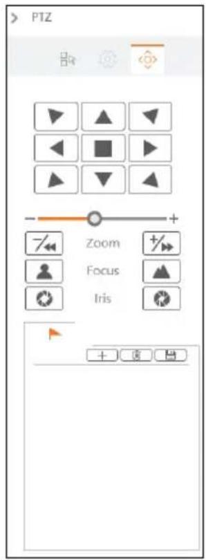
Click on the camera window in the preview area, then click Main Stream to set the camera's live preview stream to the mainstream in manual record mode.
Click Sub-stream to set the camera's live preview stream to sub-stream. In the stream tab, set the resolution, FPS and bitrate, then click "Apply" to save the settings.
• Operation Panel Introduction
| Button | Meaning |
 | Click to snap. |
 | Click to zoom in on the image of the camera, then drag the mouse on the camera image to view the hidden area. |
 | Click to zoom out the image of the camera. |
 | Click to close the preview camera. |
 | Click to enable audio, then drag the slider bar to adjust the volume. You can listen to the camera audio by enabling audio. |
• PTZ Panel Introduction
| Button | Meaning | |
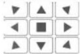 | Click ▲ / ▶ / ▼ / ▼ / ▶ / ▶ / ▶ / ▶ to rotate the dome; click ■ to stop rotating the dome. | |
 | Drag the slider to adjust the rotating speed of the dome. | |
 | Click +/→ / -/→ to zoom in/out camera image. | |
 | Click ▲ / ▶ to increase/ decrease the focal length. | |
 | Click ⚙ / ⚙ to increase/decrease the iris of the dome. | |
10.3.2 Remote Configuration
Click "Function Panel" in the remote interface to configure the camera, event, network, account authority and system of the encoder remotely. All these settings are like that of the local encoder settings. See the configurations of the encoder for details.
11 Specifications
| VIDEO | ||
| Video input | Signal technology | HD over Coax® technology with HD-Analog, HD-TVI, HD-CVI and CVBS up to 960H |
| Signal type | HD-TVI/HD-Analog/HD-CVI:4K at 15fps, 5MPat 20fps4MP, 2.1MP/1080p,960H,D1 at 30fps | |
| CH# | 16CH BNC input | |
| Video output | Outputs | True HD, VGA, BNC (1.0Vp-p; 75Ω) |
| Resolutions | True HD: 3840 × 2160, 1920 × 1080, 1280 × 1024VGA: 1920 × 1080, 1280 × 1024BNC: CVBS, 960H | |
| Display mode (local) | 1, 4, 9, 16, split | |
| Compression | H.265, H.264 | |
| PERFORMANCE | ||
| Interface | Audio in/out | 8 RCA input / 1 RCA output (600Ω) |
| Audio codec | G.711(U/A) | |
| Alarm input | 16 alarm inputs | |
| Alarm output | 4 alarm outputs | |
| Serial (RS485, USB, UTC) | 1 RS485 port for PTZ support | |
| 1x USB 3.0, 1x USB 2.0 | ||
| PTZ control via Coax (HD-Analog / HD-TVI) | ||
| Features | Motion detection | Yes |
| Privacy masks | Yes (up to 4 masks per channel) | |
| Alarm management | Locally and via DW Spectrum® IPVMS.Motion detection, sensor and alarm activation, video loss, system start and user login. | |
| Notifications | Notifications via e-mail, local popup display, alarm output, buzzer, push text, FTP, snapshot, PTZ preset activation | |
| Security | HTTP, multi-user authority | |
| NETWORK | ||
| Network connection | 1x RJ45 10/100/1000 Base-T | |
| Streaming | Transmission speed live | 4K: 8fps5MP: 12fps4MP: 15fpsUp to 2.1MP/1080p: 30fps |
| Max. throughput | 96Mbps | |
| Bitrate mode | CBR, VBR | |
| Max Bitrate | 32Kbps - 5Mbps | |
| Protocols | TCP/IP, DHCP, DNS, DDNS, UPnP, HTTP, NTP, SMTP, RTSP, SNMP, FTP, ONVIF | |
| Access | Web viewer | Microsoft Edge®, Google Chrome®, Mozilla Firefox®, Safari® |
| software | DW Spectrum® IPVMS | |
| GENERAL | ||
DW-ENC4K16
User Manual
| Operating temperature | 14°F - 122°F (-10°C ~ 50°C) | |
| Operating humidity | 10-90% (non-condensing) | |
| Other certifications | CE, FCC, NDAA | |
| Electrical | Power requirement | 12V DC, 4A |
| Power consumption | Max 30W, 2.5A | |
| Dimensions | 14.96" x 10.55" x 1.77" (380 × 268 × 45mm) | |
| Warranty | 2 years | |
* Specifications are subject to change without notice.
12 Warranty Information
Go to https://digital-watchdog.com/page/rma-landing-page/ to learn more about Digital Watchdog's warranty and RMA.
To obtain warranty or out-of-warranty service, please contact a technical support representative at:
1+ (866) 446-3595, Monday through Friday from 9:00 AM to 8:00 PM EST.
A purchase receipt or other proof of the date of the original purchase is needed before warranty service is rendered. This warranty only covers failures due to defects in materials and workmanship that arise during normal use. This warranty does not cover damages that occur in shipment or failures that are caused by products not supplied by the Warrantor or failures that result from accident, misuse, abuse, neglect, mishandling, misapplication, alteration, modification, faulty installation, setup adjustments, improper antenna, inadequate signal pickup, maladjustments of consumer controls, improper operation, power line surge, improper voltage supply, lightning damage, rental use of the product or service by anyone other than an authorized repair facility or damage that is attributable to acts of God.
13 Limits and Exclusions
There are no express warranties except as listed above. The Warrantor will not be liable for incidental or consequential damages (including, without limitation, damage to recording media) resulting from the use of these products or arising out of any breach of the warranty. All express and implied warranties, including the warranties of merchantability and fitness for a particular purpose, are limited to the applicable warranty period set forth above.
Some states do not allow the exclusion or limitation of incidental or consequential damages or limitations on how long an implied warranty lasts, so the above exclusions or limitations may not apply to you. This warranty gives you specific legal rights, and you may also have other rights that vary from state to state.
If the problem is not handled to your satisfaction, then write to the following address:
Digital Watchdog, Inc.
ATTN: RMA Department
16220 Bloomfield Ave
Cerritos, CA 90703
Service calls that do not involve defective materials or workmanship as determined by the Warrantor, in its sole discretion, are not covered. The cost of such service calls is the responsibility of the purchaser.
- Default Admin Login Information
- Notes
- Disclaimer
- Cybersecurity Recommendations
- Regulatory Information
- FCC Information
- CE Information
- RoHS
- Table of Contents
- Introduction....3
- Basic Operation Guide....6
- Wizard & Main Interface....8
- Camera Management....12
- Live View Introduction....13
- PTZ....17
- Event Management....20
- Account & Permission Management....28
- Device Management....36
- Remote Surveillance....51
- Specifications....57
- Warranty Information....59
- Limits and Exclusions 60
- Introduction
- What's in the Box
- Connections
- - Alarm Connections
- - Alarm Input:
- - Alarm Output:
- Basic Operation Guide
- Startup and Shutdown
- Startup
- Shutdown
- By mouse:
- Mouse Control
- Text-input Instruction
- Common Button Operation
- Wizard & Main Interface
- Startup Wizard
- Main Interface
- Camera Management
- Camera Signal
- Edit Camera
- Live View Introduction
- Live View Interface Introduction
- Image Configuration
- Encoder Parameters
- Image Settings
- Mask Settings
- PTZ
- PTZ Control Interface Introduction
- Preset Setting
- PTZ Protocol Setting
- Event Management
- Sensor Alarm
- Motion Alarm
- Motion Configuration
- Motion Alarm Handling Configuration
- Video Loss Settings
- Exception Handling Settings
- Alarm Event Notification
- Display
- Buzzer
- View Alarm Status
- Account & Permission Management
- Account Management
- Add User
- Edit User
- User Login & Logout
- Permission Management
- Add Permission Group
- Edit Permission Group
- Block and Allow Lists
- Preview On Logout
- Password Security
- View Online User
- Device Management
- Network Configuration
- TCP/IP Configuration
- Port Configuration
- DDNS Configuration
- E-mail Configuration
- UPnP Configuration
- 802.1X
- FTP Configuration
- SNMP
- ONVIF
- View Network Status
- Basic Configuration
- Common Configuration
- Date and Time Configuration
- Factory Default
- Device Software Upgrade
- Backup and Restore
- - Recover
- Restart Automatically
- View Log
- View System Information
- Remote Surveillance
- Web LAN Access
- Web WAN Access
- - Router Access
- Web Remote Control
- Remote Preview
- Plug-in Free Live View
- Plug-in Required Live View
- - Start Preview
- - Left Panel Introduction
- • Tool Bar Introduction
- • Right Panel Introduction
- • Operation Panel Introduction
- • PTZ Panel Introduction
- Remote Configuration
- Specifications
- Warranty Information
- Limits and Exclusions
Brand : Digital Watchdog
Model : DW-ENC4K16
Category : Video Surveillance