
PS-PLAY - Professional audio equipment Sonifex - Free user manual and instructions
Find the device manual for free PS-PLAY Sonifex in PDF.


| Product Type | Portable Digital Audio Player/Recorder |
| Brand | Sonifex |
| Model | PS-PLAY |
| Dimensions | 150 x 80 x 25 mm (approx.) |
| Weight | 300 g (approx.) |
| Power Supply | Built-in rechargeable Li-ion battery, USB-C charging (5V, 1A) |
| Battery Life | Up to 8 hours continuous playback |
| Supported Audio Formats | MP3, WAV, FLAC, AAC, OGG |
| Storage | microSD card slot (up to 256 GB), internal 16 GB (approx.) |
| Recording | Built-in microphone, line-in recording (WAV, MP3) |
| Playback Controls | Play/Pause, Skip, Volume, Shuffle, Repeat |
| Connectivity | USB-C, 3.5 mm headphone jack, line-out, Bluetooth 5.0 |
| Display | 2.0-inch TFT color LCD (320x240 pixels) |
| Care & Cleaning | Wipe with a soft, dry cloth. Do not use liquids or abrasives. |
| Safety | Keep away from moisture and extreme temperatures. Do not disassemble. |
| Spare Parts & Repairability | Battery and SD card slot replaceable by authorized service centers. |
| General Information | Professional-grade portable audio player for broadcast and field use. |
Frequently Asked Questions - PS-PLAY Sonifex
User questions about PS-PLAY Sonifex
0 question about this device. Answer the ones you know or ask your own.
Ask a new question about this device
Download the instructions for your Professional audio equipment in PDF format for free! Find your manual PS-PLAY - Sonifex and take your electronic device back in hand. On this page are published all the documents necessary for the use of your device. PS-PLAY by Sonifex.
USER MANUAL PS-PLAY Sonifex
Audio to IP Streaming Encoder
IP to Audio Streaming Decoder
IP to Speakers Streaming Decoder

Manufacturers of audio & video
products for radio & TV broadcasters
SONIFEX
Pro Audio Streamers Handbook
For the latest Sonifex handbook information please visit the Sonifex website at www.sonifex.co.uk
This handbook is for use with the following product:
PS-SEND Audio to IP Streaming Encoder
PS-PLAY IP to Audio Streaming Decoder
PS-AMP IP to Speakers Streaming Decoder
AW10463 Stock Code: 30-258
Revision 2.04, February 2020
©Sonifex Ltd, 2020
All Rights Reserved
Sonifex Ltd, 61, Station Road, Irthlingborough,
Northants, NN9 5QE, England.
Tel: +44 (0)1933 650 700
Fax: +44 (0)1933 650 726
Email: sales@sonifex.co.uk
Website: https://www.sonifex.co.uk
Information in this document is subject to change without notice and does not represent a
commitment on the part of the vendor. Sonifex Ltd shall not be liable for any loss or damage whatsoever arising from the use of information or any error contained in this manual.
No part of this manual may be reproduced or transmitted in any form or by any means, electronic or mechanical, including photocopying, recording, information storage and retrieval systems, for any purpose other than the purchaser's personal use, without the express written permission of Sonifex Ltd. Unless otherwise noted, all names of companies, products and persons contained herein are part of a completely fictitious adaptation and are designed solely to document the use of Sonifex product.
Made in the UK by SONIFEX
Contents
Product Warranty - 2 Year Extended i
Sonifex Warranty & Liability Terms & Conditions i
Unpacking Your Product ii
Repairs & Returns iii
CE Conformity iii
Safety & Installation of Mains Operated Equipment iii
Voltage Setting Checks iii
Fuse Rating iii
Power Cable & Connection iii
WEEE Directive iv
Atmosphere/Environment iv
-
Pro Audio Streamer Introduction 1
-
PS-SEND Audio to IP Streaming Encoder 2
Introduction 2
Front Panel Controls & Operation 3
Rear Panel Connections and Operation 4
Technical Specification PS-SEND 6
- PS-PLAY IP to Audio Streaming Decoder 7
Introduction 7
Front Panel Controls & Operation 8
Rear Panel Connections and Operation 10
Technical Specification PS-PLAY 12
- PS-AMP IP to Speakers Streaming Decoder 13
Introduction 13
Front Panel Controls & Operation 13
Rear Panel Connections and Operation 15
Technical Specification PS-AMP 16
- Webpage Interface
6.How To Use Your Pro Audio Streamers 21
- Advanced 23
Boot Modes 23
PS-SEND 24
Basic Audio Settings 24
Network Settings 25
Audio Settings 25
Streaming Settings 26
Control Settings 27
Serial Settings 28
Security Page 28
Contents & Figures
PS-PLAY/PS-AMP
Unit Status 28
Basic Settings 29
Playback Settings 31
Network Settings 31
Streaming Settings 32
Playback Settings 33
Priority Stream Settings 33
Serial Settings 33
I/O Settings 33
Remote Management 34
Security
34
Figures
Fig 2-1: PS-SEND Front Panel 2
Fig 2-2: PS-SEND Power & Status LEDs 3
Fig 2-3: PS-SEND Reset Button 3
Fig 2-4: PS-SEND Headphone Socket & Volume Control 3
Fig 2-5: PS-SEND Rear Panel 4
Fig 2-6: PS-SEND XLR Analogue Inputs 4
Fig 2-7: PS-SEND RCA Phono Analogue Inputs 4
Fig 2-8 PS-SEND AES/EBU Input 4
Fig 2-9: PS-SEND S/PDIF Input 4
Fig 2-10: PS-SEND TOSLINK Input 5
Fig 2-11: PS-SEND GPIO RJ45 5
Fig 2-12: PS-SEND ETHERNET Port 5
Fig 2-13: PS-SEND RS-232 Serial Port 5
Fig 2-14: PS-SEND IEC Power Plug & Fuse 5
Fig 3-1: PS-PLAY Front Panel
Fig 3-2: PS-PLAY Power & Status LEDs 8
Fig 3-3: PS-PLAY Infra Red Receiver
Fig 3-4: PS-PLAY Reset Button 8
Fig 3-5: PS-PLAY USB Socket 9
Fig 3-6: PS-PLAY Headphone Socket, Volume Control &
Output Level Control 9
Fig 3-7: PS-PLAY Rear Panel 10
Fig 3-8: PS-PLAY Analogue Outputs 10
Fig 3-9: PS-PLAY RCA Phono Analogue Outputs 10
Fig 3-10: PS-PLAY AES/EBU Output 10
Fig 3-11: PS-PLAY S/PDIF Output 10
Fig 3-12: PS-PLAY TOSLINK Output 11
Fig 3-13: PS-PLAY GPIO RJ45 11
Fig 3-14: PS-PLAY ETHERNET Port 11
Fig 3-15: PS-PLAY RS-232 Serial Port 11
Fig 3-16: PS-PLAY IEC Power Plug & Fuse 11
Fig 4-1: PS-AMP Front Panel 13
Fig 4-2: PS-PLAY Power & Status LEDs 13
Fig 4-3: PS-AMP Infra Red Receiver 14
Fig 4-4: PS-AMP Reset Button 14
Fig 4-5: PS-AMP USB Socket 14
Fig 4-6: PS-AMP Headphone Socket, Volume Control &
Output Level Control 14
Fig 4-7: PS-AMP Rear Panel 15
Fig 4-8: PS-AMP GPIO RJ45 15
Fig 4-9: PS-AMP ETHERNET Port 15
Fig 4-10: PS-AMP RS-232 Serial Port 16
Fig 4-11: PS-AMP IEC Power Plug & Fuse 16
Fig 5-1: The PS-SEND Webpage 18
Fig 5-2: The PS-AMP Webpage 19
Fig 5-3: The PS-PLAY Webpage 19
Table 7-1: Assured Forwarding Table 27
Warranty Registration
SONIFEX
Register Online for an Extended 2 Year Warranty
As standard, Sonifex products are supplied with a 1 year back to base warranty.
If you register the product online, you can increase your product warranty to 2 years and we can also keep you informed of any product design improvements or modifications.
Product: ____ Serial No: ____
To register your product, please go online to www.sonifex.co.uk/register
Product Warranty - 2 Year Extended
As standard, Sonifex products are supplied with a 1 year back to base warranty. In order to register the date of purchase and so that we can keep you informed of any product design improvements or modifications, it is important to complete the warranty registration online. Additionally, if you register the product on the Sonifex website, you can increase your product warranty to 2 years. Go to the Sonifex website at: www.sonifex.co.uk/register to apply for your 2 year warranty.
Sonifex Warranty & Liability Terms & Conditions
1. Definitions
'the Company' means Sonifex Ltd and where relevant includes companies within the same group of companies as Sonifex Limited.
'the Goods' means the goods or any part thereof supplied by the Company and where relevant includes: work carried out by the Company on items supplied by the Purchaser; services supplied by the Company; and software supplied by the Company.
'the Purchaser' means the person or organisation who buys or has agreed to buy the Goods.
'the Price' means the Price of the Goods and any other charges incurred by the Company in the supply of the Goods.
'the Warranty Term' is the length of the product warranty which is usually 12 months from the date of despatch; except when the product has been registered at the Sonifex website when the Warranty Term is 24 months from the date of despatch.
'the Contract' means the quotation, these Conditions of Sale and any other document incorporated in a contract between the Company and the Purchaser.
This is the entire Contract between the parties relating to the subject matter hereof and may not be changed or terminated except in writing in accordance with the provisions of this Contract. A reference to the consent, acknowledgement, authority or agreement of the Company means in writing and only by a director of the Company.
2. Warranty
a. The Company agrees to repair or (at its discretion) replace Goods which are found to be defective (fair wear and tear excepted) and which are returned to the Company within the Warranty Term provided that each of the following are satisfied:
i. notification of any defect is given to the Company immediately upon its becoming apparent to the Purchaser;
ii. the Goods have only been operated under normal operating conditions and have only been subject to normal use (and in particular the Goods must have been correctly connected and must not have been subject to high voltage or to ionising radiation and must not have been used contrary to the Company's technical recommendations);
iii. the Goods are returned to the Company's premises at the Purchaser's expense;
iv. any Goods or parts of Goods replaced shall become the property of the Company;
v. no work whatsoever (other than normal and proper maintenance) has been carried out to the Goods or any part of the Goods without the Company's prior written consent;
vi. the defect has not arisen from a design made, furnished or specified by the Purchaser;
Warranty
vii. the Goods have been assembled or incorporated into other goods only in accordance with any instructions issued by the Company;
viii. the defect has not arisen from a design modified by the Purchaser;
ix. the defect has not arisen from an item manufactured by a person other than the Company. In respect of any item manufactured by a person other than the Company, the Purchaser shall only be entitled to the benefit of any warranty or guarantee provided by such manufacturer to the Company.
b. In respect of computer software supplied by the Company the Company does not warrant that the use of the software will be uninterrupted or error free.
c. The Company accepts liability:
(i) for death or personal injury to the extent that it results from the negligence of the Company, its employees (whilst in the course of their employment) or its agents (in the course of the agency);
(ii) for any breach by the Company of any statutory undertaking as to title, quiet possession and freedom from encumbrance.
d. Subject to conditions (a) and (c) from the time of despatch of the Goods from the Company's premises the Purchaser shall be responsible for any defect in the Goods or loss, damage, nuisance or interference whatsoever consequential economic or otherwise or wastage of material resulting from or caused by or to the Goods. In particular the Company shall not be liable for any loss of profits or other economic losses. The Company accordingly excludes all liability for the same.
e. At the request and expense of the Purchaser the Company will test the Goods to ascertain performance levels and provide a report of
the results of that test. The report will be accurate at the time of the test, to the best of the belief and knowledge of the Company, and the Company accepts no liability in respect of its accuracy beyond that set out in Condition (a).
f. Subject to Condition (e) no representation, condition, warranty or other term, express or implied (by statute or otherwise) is given by the Company that the Goods are of any particular quality or standard or will enable the Purchaser to attain any particular performance or result, or will be suitable for any particular purpose or use under specific conditions or will provide any particular capacity, notwithstanding that the requirement for such performance, result or capacity or that such particular purpose or conditions may have been known (or ought to have been known) to the Company, its employees or agents.
g. (i) To the extent that the Company is held legally liable to the Purchaser for any single breach of contract, tort, representation or other act or default, the Company's liability for the same shall not exceed the price of the Goods.
(ii) The restriction of liability in Condition (g)(i) shall not apply to any liability accepted by the Seller in Condition (c).
h. Where the Goods are sold under a consumer transaction (as defined by the Consumer Transactions (Restrictions on Statements) Order 1976) the statutory rights of the Purchaser are not affected by these Conditions of Sale.
Unpacking Your Product
Each product is shipped in protective packaging and should be inspected for damage before use. If there is any transit damage take pictures of the product packaging and notify the carrier immediately with all the relevant details of the shipment. Packing materials should be kept for inspection and also for if the product needs to be returned.
The product is shipped with the following equipment so please check to ensure that you have all of the items below. If anything is missing, please contact the supplier of your equipment immediately.
Item
Quantity
Product unit 1
IEC mains lead fitted with moulded mains plug 1
Handbook and warranty card 1
If you require a different power lead, please let us know when ordering the product.
Repairs & Returns
Please contact Sonifex or your supplier if you have any problems with your Sonifex product. Email technical.support@sonifex.co.uk for the repair/ upgrade/returns procedure, or for support & questions regarding the product operation.
CE Conformity
The products in this manual comply with the essential requirements of the relevant European health, safety and environmental protection legislation.
The technical justification file for this product is available at Sonifex Ltd.
The declaration of conformity can be found at: https://www.sonifex.co.uk/declarations
Safety & Installation of Mains Operated Equipment
There are no user serviceable parts inside the equipment. If you should ever need to look inside the unit, always disconnect the mains supply before removing the equipment covers. The cover is connected to earth by means of the fixing screws. It is essential to maintain this earth/ground connection to ensure a safe operating environment and provide electromagnetic shielding.
Voltage Setting Checks
Ensure that the machine operating voltage is correct for your mains power supply by checking the box in which your product was supplied. The voltage is shown on the box label. The available voltage settings are 115V, or 230V. Please note that all products are either switchable between 115V and 230V, or have a universal power supply.
Fuse Rating
The product is supplied with a single fuse in the live conducting path of the mains power input. For reasons of safety it is important that the correct rating and type of fuse is used. Incorrectly rated fuses could present a possible fire hazard, under equipment fault conditions. The active fuse is fitted on the outside rear panel of the unit.
Power Cable & Connection
An IEC power connector is supplied with the product which has a moulded plug attached.
The mains plug or IEC power connector is used as the disconnect device. The mains plug and IEC power connector shall remain readily operable to disconnect the apparatus in case of a fault or emergency.
The mains lead is automatically configured for the country that the product is being sent to, from one of:
Safety & Installation
Territory Voltage IEC Lead Type Image
| UK & Middle East 230V UK 3 pin to IEC lead | |
| Europe 230V | European Schuko round 2 pin to IEC lead |
| USA, Canada and South America | 115V 3 flat pin to IEC lead |
| Australia & New Zealand | 230V Australasian 3 flat pin to IEC lead |
Connect the equipment in accordance with the connection details and before applying power to the unit, check that the machine has the correct operating voltage for your mains power supply.
This apparatus is of a class I construction. It must be connected to a mains socket outlet with a protective earthing connection.
Important note: If there is an earth/ground terminal on the rear panel of the product then it must be connected to Earth.
WEEE Directive

The Waste Electrical and Electronic Equipment (WEEE) Directive was agreed on 13 February 2003, along with the related Directive 2002/95/EC on Restrictions of the use of certain Hazardous Substances in electrical and electronic
equipment (RoHS). The Waste Electrical and Electronic Equipment Directive (WEEE) aims to minimise the impacts of electrical and electronic equipment on the environment during their life times and when they become waste.
All products manufactured by Sonifex Ltd have the WEEE directive label placed on the case. Sonifex Ltd will be happy to give you information about local organisations that can reprocess the product when it reaches its "end of use", or alternatively all products that have reached "end of use" can be returned to Sonifex and will be reprocessed correctly free of charge.
Atmosphere/Environment
This apparatus should be installed in an area that is not subject to excessive temperature variation (<0°C, >50°C), moisture, dust or vibration.
This apparatus shall not be exposed to dripping or splashing, and no objects filled with water, such as vases shall be placed on the apparatus.
1. Pro Audio Streamer Introduction
The Pro Audio Streamers are a range of three IP to audio and audio to IP streamers which have professional analogue and digital inputs and outputs. They allow audio to be streamed around a building, WAN or LAN using IP audio and CAT5 cabling infrastructure. Typical applications include:
- As a backup STL (studio to transmitter link).
- For audio confidence monitoring in remote locations, such as at a radio transmitter site.
- For distribution of audio and music around a building, such as for passing audio to speakers in a conference room.
- As an internet-based IP music distribution system.
- As a tannoy, paging or IP based public address system.
- For in-house audio applications and distribution.
- For streaming internet radio in bars and clubs.
- For radio and music channels in hotel rooms distributed via an IP network.
- For playing audio from a PC, a jukebox application, or from a USB stick.
There are three products in the range providing encoding/decoding and streaming:
The PS-SEND converts an audio input to an IP stream.
The PS-PLAY reads an IP stream and outputs to balanced and unbalanced audio line levels.
The PS-AMP reads an IP stream and outputs audio to stereo speakers.
There are versions of the product which are rackmountable in a 1U high chassis: PS-SENDS, PS-PLAYS and PS-AMPS respectively. The functionality of the products is the same as the non-rackmount versions.
2 PS-SEND Audio to IP Streaming Encoder
2. PS-SEND Audio to IP Streaming Encoder Introduction
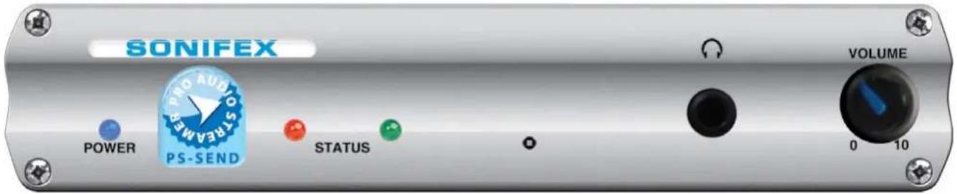
Fig 2-1: PS-SEND Front Panel
The PS-SEND is a freestanding audio to IP converter which is also available in a 1U rack-mount as the PS-SENDS. It receives audio from a number of user selectable external stereo sources including balanced and unbalanced analogue audio, AES/EBU, S/PDIF & TOSlink digital audio. Once an audio source is selected, the unit encodes the audio in real time and sends it to the network as an encoded stream. The audio stream can be distributed over an IP-based network to one or more PS-PLAY or PS-AMP units or other proprietary servers such as those for Icecast or Shoutcast.
All the configuration settings for the unit are accessed via a local web-server built into it. The type of encoding and the transport mechanism are defined by selecting the connection from a pre-defined list. The PS-SEND encodes an audio source into an MP3 (from analogue or digital inputs), G.711 or PCM (from analogue inputs only) audio stream using HTTP, RTP, raw UDP or raw TCP protocols, including multicast support and the following encoder types are available: Mpeg1 & 2 Layer3, PM3 VBR (variable bit-rate), PCM linear and A-law, U-law, with 8kHz-48kHz sample rates. The unit can configure its own IP address using DHCP/BOOTP, IPzator or AutoIP. A readout of the set IP address can be heard on every reset using SONICIP technology, if selected. Remote level monitoring is also possible using SNMP traps.
Two red and green front panel LEDs indicate what state the unit is currently in, be it normal operational mode or bootstrap mode, and also indicates the current network connection status. A blue LED denotes power to the unit. The input being routed to the IP stream can be monitored on the front panel 14 " (6.35mm) stereo jack socket in combination with a headphone volume knob.
The rear panel has 2 x RJ45 connectors, one for the 10/100Mbit Ethernet interface and one for GPI connections. The PS-SEND has 6 x GPIs which can be used to trigger the sending of the audio stream and which can also be used to trigger remote events using an output relay on the PS-PLAY and PS-AMP. There is a 9 way D-type RS232 serial connection for control of the unit by automation systems and firmware updates. The unit can be remote controlled via serial connection, TCP or UDP.
Power to the unit is via a universal supply 85V - 264V fused IEC mains socket.
Front Panel Controls & Operation
All controls and indicators are located on the front panel.
POWER LED
When on this blue LED indicates that the unit is powered.
STATUS LEDs
There are two LEDs, red and green, which together indicate boot up errors and when data is being sent. The LEDs have the following meanings:
| Red LED Green LED Status | Description | ||
| Flashing On Boot | Load | The boot loader is running to start the unit. | |
| Flashing Continuously | Flashes 5 Times | Boot Up The | the unit is attempting to configure an IP address. |
| On Flashes 5 | Times | Boot Up Error - the PS-SEND application programme is corrupted or there is an IP address conflict. | |
| On Flashes 3 | Times | Boot Up Error – the network hardware could not be initialised or the MAC address is corrupted. | |
| Off On Running | The unit is running but not sending data. | ||
| Off Flashing Running | The unit is running and sending data. | ||
Reset Button
The Reset button is used to restart the firmware and re-initialise the unit. Please use this button in the unlikely scenario of unit failure.
Headphone Output & Volume Control
The headphone output is a 14 " stereo jack socket, designed to drive 150 mW into 32Ω to 600Ω professional headphones. It is used to monitor the currently selected input source.
The headphone output has its own volume control and has a maximum output level of +12dBu.

Fig 2-2: PS-SEND Power & Status LEDs

Fig 2-3: PS-SEND Reset Button
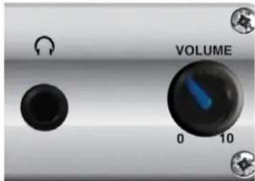
Fig 2-4: PS-SEND Headphone Socket & Volume Control
2 PS-SEND Audio to IP Streaming Encoder
Rear Panel Connections and Operation
All the audio connectors together with the ethernet, serial and GPI/O connectors are found on the rear panel of the unit. All the audio connections are inputs on this unit.

Fig 2-5: PS-SEND Rear Panel
Balanced Analogue Inputs
The two XLR 3 pin sockets used for the left and right channel inputs are electronically balanced and have an impedance of >10kΩ bridging. Each XLR has the following
connections:
Pin 1: Screen.
Pin 2: Phase.
Pin 3: Non-phase.
Unbalanced Analogue Inputs
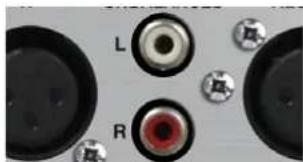
The two left and right RCA inputs are unbalanced and have an impedance of >20kΩ. They are connected as follows:
Pin: Signal
Ring: Screen

natural_image
Two black circular objects with small circular features, no visible text or symbolsFig 2-6: PS-SEND XLR Analogue Inputs
natural_image
Close-up of electronic components including a speaker, lens, and speaker with no visible text or symbolsFig 2-7: PS-SEND RCA Phono Analogue Inputs
AES/EBU Balanced
Digital Input
The stereo digital input XLR 3 pin socket has an impedance of 110Ω and the following connections:
Pin 1: Screen
Pin 2: Phase
Pin 3: Non-phase
The signals on this connector should meet the IEC 60968 specification
S/PDIF Unbalanced
Digital Input
The stereo S/PDIF Input is an RCA phono connector and is typically used for consumer digital audio. The S/PDIF inputs have an impedance of 75Ω.
Pin: Signal
Ring: Screen

natural_image
Close-up of electronic components including a speaker, lenses, and a screen (no visible text or symbols)Fig 2-8 PS-SEND AES/EBU Input

Fig 2-9: PS-SEND S/PDIF Input
TOSLINK Unbalanced Digital Input
The stereo TOSlink optical connector is an unbalanced S/PDIF input. This is typically used for consumer digital audio.
GPIO General Purpose Inputs
An RJ45 connector is used for the GP inputs. The GPIs are used to control the stream output and there are six in total. Only one is used at any one time, which is chosen from the webpage interface. The input can be configured as active open or active closed.
A ground reference is also supplied on Pin 8. Simply short the relevant input pin to the DGND pin through a button or switch to register a press. The pinout for the connector is as follows:
Pin 1: GPI1
Pin 2: GPI2
Pin 3: GPI3
Pin 4: GPI4
Pin 5: GPI5
Pin 6: GPI6
Pin 7: N/C
Pin 8: Digital Ground (DGND)
Ethernet Port
The 10/100Mbit ethernet port is a metallic RJ45 with embedded LEDs which is used to connect the unit to an IP network. Any standard CAT5 cable can be used. There are two embedded indication LEDs which relay the following information:

Fig 2-10: PS-SEND TOSLINK Input
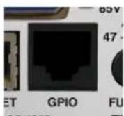
Fig 2-11: PS-SEND
GPIO RJ45

Fig 2-12: PS-SEND ETHERNET Port
Green LED: Illuminates permanently when a Link has been established.
Yellow LED: On power up, flashes periodically while waiting for a connection. Once a connection is established, it flashes whenever data is throughput.
The connector is wired as follows:
Pin 1: Receive data+
Pin 2: Transmit data+
Pin 3: Transmit data+
Pin 6: Receive data-
Pin 5: Ground
All other pins are unused.
RS232 Serial Port
This is a 9 pin D-type socket which can be used to update the firmware or send commands to the unit. The connections are as follows:
Pin 2: Transmit data
Pin 3: Receive data
Pin 5: Ground
All other pins are unused.
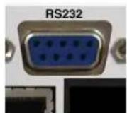
Fig 2-13: PS-SEND RS-232 Serial Port
IEC Power Plug & Fuse
The IEC power plug is a universal filtered IEC, continuously rated 85-264VAC @47-63Hz, max 10W.
The fuse socket is a where the anti-surge fuse 1A 20 x 5mm fuse is inserted. Please unplug the unit whenever opening this cover.
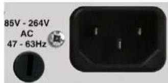
Fig 2-14: PS-SEND IEC Power Plug & Fuse
2 PS-SEND Audio to IP Streaming Encoder
Technical Specification PS-SEND
| Analogue Inputs: 2 x XLR 3 pin (balanced)( L&R) |
| 2 x RCA phono (unbalanced)( L&R) |
| Analogue Max Input Level: 18dBu XLR balanced8dBu RCA phono unbalanced |
| Analogue Balanced | 20kΩ |
| Input Impedance: | |
| Analogue Input SNR: 74dB |
| Input THD: 0.02% Relative |
| Interchannel Isolation | 80dB (Ref FSD) |
| (Cross Talk): | |
| Digital Inputs: 1 x AES/EBU XLR 3 pin female |
| 1 x S/PDIF RCA phono |
| 1 x TOSLink optical input |
| Analogue Outputs: 1 x 1⁄4 inch jack headphone socket |
| Headphones Output: Drives 150mW into 32Ω to 600kΩ stereo headphones |
| GPIs (General 6 x GPIs, selectable via webpage control on Purpose Inputs): RJ45 socket |
| Serial Port: 1 x 9 way D-type socket, used to send control commands and update firmware |
| Ethernet Port: 1 x RJ45 socket. Remote control commands can be sent via TCP or UDP as well as firmware updates. |
| Mains Input: | Filtered IEC, 85 - 264VAC, 47 - 63 Hz,10W, max |
| Fuse Rating: | Anti-surge fuse 1A 20 x 5mm |
Audio Codec Specifications Encoder
G.711 (U Law/A Law 8kHz to 48kHz sampling rate)
WAV (IMA ADPCM+ 16bit PCM uncompressed: 8kHz to 48kHz)
MP3 MPEGv1 Layer 3 (32, 44.1 and 48 kHz, CBR)
MP3 MPEGv2 Layer 3 (16, 22.05 and 24 kHz, CBR)
Supported Network Transport Protocols
| RTP - UDP |
| HTTP - TCP |
| Raw UDP |
| Raw TCP |
| Can also act as Icecast/Shoutcast source |
| SNMP - traps for remote management |
| DHCP, BOOTP, IPZator or AUTOIP - Dynamic IP address resolution |
| SonicIP IP Address readout |
Equipment Type:
| PS-SEND | Audio to IP Streaming Encoder |
| PS-SENDS | Audio to IP Streaming Encoder, 19" (48cm) Rack Mounted |
Physical Specification
| PS-SEND | |
| Dimensions (Raw): | 22cm (W) x 13.7cm (D) x 4.3cm (H) |
| 8.67" (W) x 5.39" (D) x 1.7" (H) | |
| (Boxed): | 34cm (W) x 27cm (D) x 6cm (H) |
| 13.4" (W) x 10.6" (D) x 2.4" (H) | |
| Weight: | Nett: 0.84kg | Gross: 1.64kg |
| Nett: 1.85lbs | Gross: 3.6lbs |
PS-SENDS
| Dimensions (Raw): | 48.3cm (W) x 13.7cm (D) x 4.3cm (H) |
| 19" (W) x 5.39" (D) x 1.7" (H) | |
| Dimensions (Boxed): | 58.8cm (W) x 27cm (D) x 6.8cm (H) |
| 23" (W) x 10.6" (D) x 2.7" (H) | |
| Weight: | Nett: 1.34kg Gross: 2.14kg |
| Nett: 2.95lbs Gross: 4.7lbs | |
3. PS-PLAY IP to Audio Streaming Decoder Introduction

Fig 3-1: PS-PLAY Front Panel
The PS-PLAY is a freestanding IP to audio converter which is also available in a 1U rack-mount as the PS-PLAYS. It takes an IP audio feed and converts it to a number of simultaneous stereo outputs: balanced and unbalanced analogue audio, AES/EBU, S/PDIF & TOSlink digital audio outputs.
As for the PS-SEND, all the configuration settings for the unit are accessed via a local web-server built into it. The unit can decode one of a number of audio streams, such as those generated by the PS-SEND (MP3, G.711 and PCM) and including Ogg Vorbis and WMA audio files from external USB as well as from sources such as Shoutcast, Icecast (Internet radio), VLC and from RTP servers. The unit can receive streams from HTTP (TCP/IP) and RTP (UDP) protocols, as well as raw TCP and UDP packets. The unit can also configure its own IP address using DHCP/BOOTP, IPzator or AutoIP. A readout of the set IP address can be heard on every reset using SONICIP technology, if selected.
Two red and green front panel LEDs indicate what state the unit is currently in, be it normal operational mode or bootstrap mode, and also indicates the current network connection status. A blue LED denotes power to the unit. The audio output can be monitored on the front panel 14 (6.35mm)
stereo jack socket in combination with a headphone volume knob. The analogue audio outputs can be switched to be either a fixed level output or to be controlled by the front panel volume knob. The volume can also be adjusted, as well as many other features, using an infra-red remote control (available separately).
The PS-PLAY can be configured with up to 3 sources. The sources are prioritized in number order. If one has failed, the next one will attempt to play. If all fail, an external USB drive will be used as a back-up source. The external USB plugs into the USB socket on the front of the unit. This enables the PS-PLAY to act as a USB audio player, playing any of the audio formats previously mentioned.
The rear panel has 2 x RJ45 connectors, one for the 10/100Mbit Ethernet interface and one for GPIO connections. The PS-PLAY has 2 output relay contacts which can be triggered remotely over IP from a connected PS-SEND unit. There is a 9 way D-type RS232 serial connection for control of the unit by automation systems and for firmware updates. The unit can be remote controlled via serial connection, TCP or UDP and remote management of the unit is also possible using SNMP traps.
3 PS-PLAY IP to Audio Streaming Decoder
Front Panel Controls & Operation
All controls and indicators are located on the front panel.
POWER LED
When on this blue LED indicates that the unit is powered.
STATUS LEDs
There are two LEDs, red and green, which together indicate boot up errors and when data is being received. The LEDs have the following meanings:
| Red LED Green LED Status Description | |||
| Flashing On Boot Load The boot loader is running to start the unit. | |||
| Flashing Continuously | Flashes 5 Times Boot Up The unit is attempting to configure an IP address. | ||
| Off On Running The unit is running but not receiving data. | |||
| Off Quick Flashing Running The unit is receiving data. | |||
| Off Blinks once every 2 seconds | Running Unit is playing URL 1 | ||
| Off Blinks twice every 2 seconds | Running Unit is playing URL 2 | ||
| Off Blinks three times every 2 seconds | Running Unit is playing URL 3 | ||
| Off Blinks four times every 2 seconds | Running Unit is playing priority URL | ||
Infra Red Receiver
Some basic functions can be controlled by an IR-Remote which is supplied. Point the IR Receiver at this LED.
Reset Button
The Reset button is used to restart the firmware and re-initialise the unit. Please use this button in the unlikely scenario of unit failure.

Fig 3-2: PS-PLAY Power & Status LEDs

natural_image
A plain gray gradient background with a single circular brown dot in the center (no text or symbols)Fig 3-3: PS-PLAY Infra Red Receiver

natural_image
Close-up of a USB flash drive with two buttons and a battery (no visible text or symbols)Fig 3-4: PS-PLAY Reset Button
USB Socket
The USB socket is available so that playlists stored on a USB stick can be played from the PS-PLAY. Set up the playlist on the USB stick and insert it into this socket.
The USB port is not fully USB 1.1 compatible and has the following limitations:
- Only the Mass Storage class is supported.
- HUBs are not supported (certain flash disks contain an embedded hub).
- Only the first partition is supported.
• The partition must be formatted as FAT16. - It can only read a maximum partition size of 4GB.
Most of the existing USB flash disks are supported.
Headphone Output & Volume Control
The headphone output is a 14 " stereo jack socket, designed to drive 150 mW into 32Ω to 600Ω professional headphones. It is used to monitor the currently selected output.
The headphone output has its own volume control and has a maximum output level of +12dBu.
Output Level Control
The O/P LEVEL button allows you to have either a FIXED level output (button depressed) or to have the output level adjustable by using the front panel VOLUME control.

Fig 3-5: PS-PLAY USB Socket

Fig 3-6: PS-PLAY Headphone Socket, Volume Control & Output Level Control
3 PS-PLAY IP to Audio Streaming Decoder
Rear Panel Connections and Operation

Fig 3-7: PS-PLAY Rear Panel
All audio connections are outputs on this unit.
Balanced Analogue Outputs The two XLR 3 pin plugs used for the left and right channel outputs are electronically balanced and have an impedance of <50Ω. Each XLR has the following connections:
Pin 1: Screen.
Pin 2: Phase.
Pin 3: Non-phase.
Unbalanced Analogue Outputs The two left and right RCA outputs are unbalanced and have an impedance of <75Ω . They are connected as follows:
Pin: Signal
Ring: Screen

natural_image
Close-up of two black circular electronic components with three gold pins, mounted on a surface with four metallic tabs (no text or symbols visible)Fig 3-8: PS-PLAY Analogue Outputs
AES/EBU Balanced Digital Output The stereo digital output XLR 3 pin plug has an impedance of 110Ω and the following connections:
Pin 1: Screen
Pin 2: Phase
Pin 3: Non-phase
The signals on this connector should meet the IEC 60968 specification

natural_image
Close-up of a black electrical connector with gold contacts and surrounding components (no visible text or symbols)Fig 3-10: PS-PLAY AES/EBU Output

natural_image
Close-up of black electronic components with labeled parts (L and R), no readable text or symbols beyond labelsFig 3-9: PS-PLAY RCA Phono Analogue Outputs
S/PDIF Unbalanced Digital Output The stereo S/PDIF Input is an RCA phono connector and is typically used for consumer digital audio. The S/PDIF inputs have an impedance of 75Ω.
Pin: Signal
Ring: Screen

natural_image
Close-up of electronic components including a S/PDIF lens, USB port, and connectors (no readable text or symbols)Fig 3-11: PS-PLAYS/PDIF Output
TOSLINK Unbalanced Digital Output
The stereo TOSlink optical connector is an unbalanced S/PDIF output. This is typically used for consumer digital audio.
GPIO General Purpose Outputs
An RJ45 connector is used for the GP outputs.
There are 2 output relay contacts which switch simultaneously and which can be triggered remotely over IP from a connected PS-SEND unit. There is a normally open and normally closed connection, per relay connection, as well as a common for each. This is configured using the web interface.
The pinout for the connector is as follows:
Pin 1: Not used
Pin 2: Digital Ground (DGND)
Pin 3: Relay Normally Open - connection 1
Pin 4: Relay Common - connection 1
Pin 5: Relay Normally Closed - connection 1
Pin 6: Relay Normally Open - connection 2
Pin 7: Relay Common - connection 2
Pin 8: Relay Normally Closed – connection 2
Ethernet Port
The 10/100Mbit ethernet port is a metallic RJ45 with embedded LEDs which is used to connect the unit to an IP network. Any standard CAT5 cable can be used. There are two embedded indication LEDs which relay the following information:
Green LED: Illuminates permanently when a Link has been established.

Fig 3-12: PS-PLAY TOSLINK Output

Fig 3-13: PS-PLAY GPIO RJ45

Fig 3-14: PS-PLAY ETHERNET Port
Yellow LED: On power up, flashes periodically while waiting for a connection. Once a connection is established, it flashes whenever data is throughput.
The connector is wired as follows:
Pin 1: Receive data+
Pin 2: Transmit data+
Pin 3: Transmit data+
Pin 6: Receive data-
Pin 5: Ground
All other pins are unused.
RS232 Serial Port
This is a 9 pin D-type socket which can be used to update the firmware or send commands to the unit. The connections are as follows:
Pin 2: Transmit data
Pin 3: Receive data
Pin 5: Ground
All other pins are unused.

Fig 3-15: PS-PLAY RS-232 Serial Port
IEC Power Plug & Fuse
The IEC power plug is a universal filtered IEC, continuously rated 85-264VAC @47-63Hz, max 10W.
The fuse socket is a where the anti-surge fuse 1A 20 x 5mm fuse is inserted. Please unplug the unit whenever opening this cover.

Fig 3-16: PS-PLAY IEC Power Plug & Fuse
3 PS-PLAY IP to Audio Streaming Decoder
Technical Specification PS-PLAY
Analogue Outputs: 2 x XLR 3 pin (balanced)(L&R)
2 x RCA phono (unbalanced)(L&R)
1 x ¼ inch (6.35mm) stereo jack headphone socket
Analogue Max Output 18dBu XLR balanced Level: 8dBu RCA phono unbalanced
Analogue Balanced Output <50Ω Impedance:
Analogue Unbalanced <75Ω Output Impedance:
Analogue Output SNR: 94dB
Output THD: 0.03% Relative Interchannel Isolation 80dB (Ref FSD) (Cross Talk):
Analogue Output -60dB to 18dB via front panel control Gain Range: knob, or optional IR controller
Digital Outputs: 1 x AES/EBU XLR 3 pin female 1 x S/PDIF RCA phono 1 x TOSLink optical input
Headphones Output: Drives 150mW into 32ohm to 600ohm stereo headphones
USB Port: 1 x USB A socket
GPOs (General Purpose 2 x switchable relay contacts Outputs): (simultaneously switched controlled from PS-SEND
Serial Port: 1 x 9 way D-type socket, used to send control commands and update firmware
Ethernet Port: 1 x RJ45 socket. Remote control commands can be sent via TCP or UDP as well as firmware updates.
IR Remote Receiver: Remote commands can be sent using optional remote control via built in IR sensor
Mains Input: Filtered IEC, 85 - 264VAC, 47 - 63 Hz, 10W max
Fuse Rating: Anti-surge fuse 1A 20 x 5mm
Audio Codec Specifications Decoder
G.711 (U Law/A Law 8kHz to 48kHz sampling rate) WAV (IMA ADPCM+ 16bit PCM uncompressed: 8kHz to 48kHz) MP3 MPEGv1 Layer 3 (32, 44.1 and 48kHz, CBR +VBR +ABR) MP3 MPEGv2 Layer 3 (16, 22.05 and 24kHz, CBR +VBR +ABR) Ogg Vorbis (floor 1)
Supported Network Transport Protocols
RTP - UDP HTTP - TCP Raw UDP Raw TCP SNMP - traps for remote management DHCP, BOOTP, IPZator or AUTOIP - Dynamic IP address resolution SonicIP IP Address readout
Equipment Type:
| PS-PLAY | IP to Audio Streaming Decoder |
| PS-PLAYS19" (48cm) Rack Mounted | IP to Audio Streaming Decoder, |
Physical Specification
PS-PLAY
Dimensions (Raw): 22cm (W) x 13.7cm (D) x 4.3cm (H) 8.67" (W) x 5.39" (D) x 1.7" (H)
Dimensions (Boxed): 34cm (W) x 27cm (D) x 6cm (H) 13.4" (W) x 10.6" (D) x 2.4" (H)
Weight: Nett: 0.84kg Gross: 1.64kg Nett: 1.85lbs Gross: 3.6lbs
PS-PLAYS
Dimensions (Raw): 48.3cm (W) x 13.7cm (D) x 4.3cm (H) 19" (W) x 5.39" (D) x 1.7" (H) Dimensions (Boxed): 58.8cm (W) x 27cm (D) x 6.8cm (H) 23" (W) x 10.6" (D) x 2.7" (H)
Weight: Nett: 1.34kg Gross: 2.14kg Nett: 2.95lbs Gross: 4.7lbs
4. PS-AMP IP to Speakers Streaming Decoder Introduction

Fig 4-1: PS-AMP Front Panel
The PS-AMP is a freestanding unit which converts an IP audio stream directly to speaker outputs. It is also available in a 1U rack-mount as the PS-AMPS. The PS-AMP has the same feature-set as the PS-PLAY except that there are no individual audio outputs other than the speaker terminals. The PS-AMP uses an integrated 2 x 15W D-class amplifier to deliver audio directly to a pair of connected speakers.
Front Panel Controls & Operation
All controls and indicators are located on the front panel.
POWER LED
When on this blue LED indicates that the unit is powered.
STATUS LEDs
There are two LEDs, red and green, which together indicate boot up errors and when data is being received. The LEDs have the following meanings:

Fig 4-2: PS-PLAY Power & Status LEDs
4 PS-AMP IP to Speakers Streaming Decoder
| Red LED G | Green LED Status Description | |
| Flashing On | Boot Load | The boot loader is running to start the unit. |
| On Blinks | Once | Boot Up Initialising boot up. |
| Flashing Off | Boot Up The unit is at | tempting to configure an IP address. |
| On Flashes | 5 Times | Boot Up Error - the PS-AMP application programme is corrupted or there is an IP address conflict. |
| On Flashes | 3 Times | Boot Up Error - the network hardware could not be initialised or the MAC address is corrupted. |
| Off On Running | The unit is running | but not receiving data. |
| Off Off Running | The unit is running | and receiving data. |
Infra Red Receiver
Some basic functions can be controlled by an IR-Remote which is supplied. Point the IR Receiver at this LED.
Reset Button
The Reset button is used to restart the firmware and re-initialise the unit. Please use this button in the unlikely scenario of unit failure.

Fig 4-3: PS-AMP
Infra Red
Receiver

Fig 4-4: PS-AMP Reset Button
USB Socket
The USB socket is available so that playlists stored on a USB stick can be played from the PS-AMP Set up the playlist on the USB stick and insert it into this socket.
The USB port is not fully USB 1.1 compatible and has the following limitations:
- Only the Mass Storage class is supported.
- HUBs are not supported (certain flash disks contain an embedded hub).
- Only the first partition is supported.
• The partition must be formatted as FAT16. - It can only read a maximum partition size of 4GB. Most of the existing USB flash disks are supported.
Headphone Output & Volume Control
The headphone output is a 14 " stereo jack socket, designed to drive 150 mW into 32Ω to 600Ω professional headphones. It is used to monitor the currently selected output.
The headphone output has its own volume control and has a maximum output level of +12dBu.

Fig 4-6: PS-AMP Headphone Socket, Volume Control & Output Level Control
Output Level Control
The O/P LEVEL button allows you to have either a FIXED level output (button depressed) or to have the output level adjustable by using the front panel VOLUME control.

Fig 4-5: PS-AMP USB Socket
Rear Panel Connections and Operation

Fig 4-7: PS-AMP Rear Panel
Speaker Terminals
These stereo speaker terminal blocks are for connecting a pair of 8 or 16ohm speakers. There are two connections each for left and right speakers, positive terminals in red and a negative terminals in black. Please ensure these are wired correctly. Generally the speaker cable will be coloured or will have an identification for he positive cable.
L+ Red connector
L- Black connector
R- Black connector
R+ Red connector
GPIO General Purpose Outputs
An RJ45 connector is used for the GP outputs. There are 2 output relay contacts which switch simultaneously and which can be triggered remotely over IP from a connected PS-SEND unit. There is a normally open and normally closed connection, per relay connection, as well as a common for each. This is configured using the web interface.
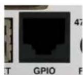
Fig 4-8: PS-AMP
GPIO RJ45
The pinout for the connector is as follows:
Pin 1: Not used
Pin 2: Digital Ground (DGND)
Pin 3: Relay Normally Open - connection 1
Pin 4: Relay Common - connection 1
Pin 5: Relay Normally Closed - connection 1
Pin 6: Relay Normally Closed - connection 2
Pin 7: Relay Common - connection 2
Pin 8: Relay Normally Open - connection 2
Ethernet Port
The 10/100Mbit ethernet port is a metallic RJ45 with embedded LEDs which is used to connect the unit to an IP network. Any standard CAT5 cable can be used. There are two embedded indication LEDs which relay
the following information:
Green LED: Illuminates permanently when a Link has been established.
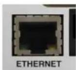
Fig 4-9: PS-AMP ETHERNET Port
4 PS-AMP IP to Speakers Streaming Decoder
Yellow LED: On power up, flashes periodically while waiting for a connection. Once a connection is established, it flashes whenever data is throughput.
The connector is wired as follows:
Pin 1: Receive data+
Pin 2: Transmit data+
Pin 3: Transmit data+
Pin 6: Receive data-
Pin 5: Ground
All other pins are unused.
RS232 Serial Port
This is a 9 pin D-type socket which can be used to update the firmware or send commands to the unit. The connections are as follows:
Pin 2: Transmit data
Pin 3: Receive data
Pin 5: Ground
All other pins are unused.

Fig 4-10: PS-AMP RS-232 Serial Port
IEC Power Plug & Fuse
The IEC power plug is a universal filtered IEC, continuously rated 85-264VAC @47-63Hz, max 10W.
The fuse socket is a where the anti-surge fuse 1A 20 x 5mm fuse is inserted. Please unplug the unit whenever opening this cover.

Fig 4-11: PS-AMP IEC Power Plug & Fuse
Technical Specification PS-AMP
Analogue Outputs: 2 x speaker connectors (2 each black and red terminals)
1 x ¼ inch (6.35mm) stereo jack headphone socket
Headphones Output: Drives 150mW into 32Ω to 600Ω stereo headphones
Headphone Level Range: -60dB – 18dB via front panel control knob or optional IR controller
USB Port: 1 x USB A socket
GPOs (General Purpose 2 x switchable relay contacts (simultaneously Outputs): switched) controlled from PS-SEND
Serial Port: 1 x 9 way D-type socket, used to send control commands and update firmware
Ethernet Port: 1 x RJ45 socket. Remote control commands can be sent via TCP or UDP as well as firmware updates.
IR Remote Receiver: Remote commands can be sent using optional remote control via built in IR sensor
Speaker Power: 15W per channel into 8ohm @ 10% THD+N
Mains Input: Filtered IEC, 85 - 264VAC, 47 - 63 Hz, 60W max
Fuse Rating: Anti-surge fuse 1A 20 x 5mm
Audio Codec Specifications Decoder
G.711 (U Law/A Law 8kHz to 48kHz sampling rate) WAV (IMA ADPCM+ 16bit PCM uncompressed: 8kHz to 48kHz) MP3 MPEGv1 Layer 3 (32, 44.1 and 48kHz, CBR +VBR +ABR) MP3 MPEGv2 Layer 3 (16, 22.05 and 24kHz, CBR +VBR +ABR) Ogg Vorbis (floor 1)
Supported Network Transport Protocols
RTP - UDP
HTTP - TCP
Raw UDP
Raw TCF
SNMP - traps for remote management
DHCP, BOOTP, IPZator or AUTOIP - Dynamic IP address resolution
SonicIP IP Address readout
Equipment Type:
PS-AMP IP to Speakers Streaming Decoder
PS-AMPS IP to Speakers Streaming Decoder, 19"(48cm) Rack Mounted
Physical Specification
PS-AMP
Dimensions (Raw): 22cm (W) x 13.7cm (D) x 4.3cm (H)
8.67" (W) × 5.39" (D) × 1.7" (H)
Dimensions (Boxed): 34cm (W) x 27cm (D) x 6cm (H)
13.4" (W) × 10.6" (D) × 2.4" (H)
Weight: Nett: 0.84kg Gross: 1.64kg
Nett: 1.85lbs Gross: 3.6lbs
PS-AMPS
Dimensions (Raw): 48.3cm (W) x 13.7cm (D) x 4.3cm (H)
19" (W) x 5.39" (D) x 1.7" (H)
Dimensions (Boxed): 58.8cm (W) x 27cm (D) x 6.8cm (H)
5. Webpage Interface
The Pro Audio Streamers have a built in webpage to configure them. The following section will guide you through the process of accessing the webpage. Please read all the steps before starting the process.
- Power the unit and connect the ethernet cable to the PC or laptop that you'll use to access the webpage.
- The unit will be assigned an IP address and this is spoken as audio through the headphone socket after power up. Connect a pair of headphones, listen to the IP address and write it down. An example of an IP Address is '192.168.0.100' (with decimal point described as a 'dot').
- Open an internet browser and type 'http://' followed by your IP address, so using the example above, http://192.168.0.100
- The 'basic settings' page should now open. Please note that for this to work, you may need to alter the IP address of your laptop so that it has the same subnet as the Pro Audio Streamer. In the above example, your laptop/PC should have an IP address of 192.168.0.xxx (where xxx is between 0 & 255) in order for it to connect correctly.

Fig 5-1: The PS-SEND Webpage

Fig 5-2: The PS-AMP Webpage
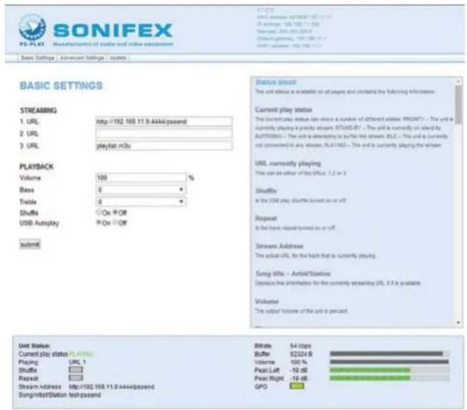
Fig 5-3: The PS-PLAY Webpage
5 Webpage Interface
The Title Bar
This contains the company logo and the logo for the product, showing that you are connected to the right product type. Also, the current webpage version and IP data is displayed here. Under the logo is the menu bar where the page selection is made. There are three options:
- Basic Settings – This is the default page where all the basic settings are selected.
- Advanced Settings – This option provides a drop down menu where all the advanced pages are selectable by category. A guide to using the advanced pages is provided elsewhere.
- Update – This allows firmware updates on the Pro Audio Streamer to be carried out.
Simply click on which page you would like to select and it will load into the browser.
The Data Section
This section provides the main data for the selected page. Each page has a title written in bold, blue text, which is capitalised. Next to the title, there is a question mark. Click on the question mark to reveal a help box on the right of the data section which will give tips on setting up the unit.
Under each title are the basic options for setup. To enter your own settings, change the required parameter and hit the submit button at the bottom of the page. If you change your mind and want to return all settings to as they were before the change, refresh the page in your browser.
The Help Box
The Help Box to the right of the screen contains tips and guidance for setting up the unit. All of the information contained in the advanced section of the manual is contained within this box.
The Status Box
The status box is the blue box located at the bottom of the page. In here, the unit status is presented. The values that are shown are snapshots of a dynamic value, so remember to refresh the page to get an accurate picture of the current scenario.
The webpage is compatible with all major browsers, including internet Explorer, safari, opera, firefox and chrome. Please note that the webpage requires Javascript to be enabled to function properly.
Configuring The Pro Audio Streamer
The next chapter contains some application notes on setting up the webpage for particular applications. Use the help box if you're unsure what a particular function should do.
6. How To Use Your Pro Audio Streamers
This section of the manual outlines some applications and the webpage settings for them.
Point To Point Audio Send
When used in conjunction with a PS-PLAY or PS-AMP, the PS-SEND can be used to transfer audio from one place to another. The PS-SEND encodes the audio and sends it directly to the PS-PLAY or PS-AMP, which decodes the signal back into audio.
The following guide will show you how to configure your units to stream 44.1kHz mp3 audio to one another when connected on the same local network (LAN):
- Connect to the webpage of the PS-SEND.
Under the AUDIO SETTINGS header: - Select the appropriate input by clicking on the radio button.
- In the Encoding and Frequency boxes, select MPEG1/44.1kHz(MP3).
- In the MPEG Encoding quality box, select a minimum of '5' for audio.
Under the STREAM DESTINATION header: - In the connection type box, select 'Internet radio'.
- In the port box, type '80'.
- Press Submit.
The unit will now reset, with the new settings stored. - Connect to the PS-PLAY or PS-AMP webpage.
Under the STREAMING header - Type http://x.x.x.x:80/pssend, where x.x.x.x is the IP address of the PS-SEND unit.
- Press Apply.
The unit will now reset and the stream should begin playing.
The following guide will show you how to set up your units to stream 44.1kHz mp3 from one unit to the other when connected to external networks. This is suitable for scenarios such as a Studio Transmitter Link:
How To Configure an STL Stream of 44.1kHz mp3 From PS-SEND To PS-PLAY Or PS-AMP
- Set the PS-SEND up as previously given.
-
Connect to the IP address of the router and configure port forwarding so that:
-
Start port is defined as 80.
• End port is defined as 80. - Protocol is selected as TCP.
- IP address is set to the current IP address of the PS-SEND.
The router should now allow communication on that port number from the outside world.
Now at the PS-PLAY or PS-AMP site:
- Connect to the PS-PLAY or PS-AMP webpage.
Under the STREAMING header: - Type http://x.x.x.x:80/pssend, where x.x.x.x is the IP address of the router where the PS-SEND is.
- Press Apply.
6 How To Use Your Pro Audio Streamers
Using the PS-PLAY or PS-AMP as a USB Playout System
One of the great features of the PS-PLAY and PS-AMP is that they can be used to play directly from the USB stick plugged into them. This is really useful if a local audio source is needed as a backup for an internet stream or if you simply want to switch to a local playlist. The unit can play WMA, MP3 and ogg vorbis files directly from the drive, as well as other streams.
- Connect the USB stick with a correctly formatted playlist file. There are many free applications available on the internet which will create a .m3u playlist file for you.
- In the data section there are 3 URL boxes. Choose any URL and type file://x.m3u, where x should be replaced by the name of the playlist.
- Press Apply.
- If you chose URL1, the unit will play directly from USB. If you chose URL3, the unit will attempt to play URL1 and URL2, before playing URL3. Thus the USB can be used as a backup for if URL1 and URL2 fail.
- It is a useful idea to make a playlist of all the streams that are intended to be used, store it on the USB stick and then set URL one to read from the USB playlist. You can then cycle through the different streams at your leisure with the remote control. URL2 can be set to play another playlist, which contains local tracks as a backup.
7. Advanced
This section of the handbook deals with advanced webpage settings and also contains information found in the Help section of the webpage for reference.
Boot Modes
The unit can configure its own IP address via several methods: DHCP/BOOTP, IPzator or AutolP.
BOOTP/DHCP – These are methods are used for automatic assignment of an IP address. BOOTP is older and DHCP is more widely used. BOOTP sets the IP address and the gateway address, while DHCP will set IP address, netmask, gateway and DNS servers.
If there is no DHCP/BOOTP server available:
IPZator – This method listens on the attached network and tries to find the network address. The netmask is assumed from the network address. It also listens for a free IP address on the network. The gateway address and DNS address are left intact. Please note that it is possible with this method, for the unit to get the same IP address as a piece of equipment that is not active or off. If this occurs, as soon as the other piece of equipment becomes active, the unit will display a network collision error and go offline.
AutoIP – Automatically assigns a free IP address in the network 169.254.0.0/16. It sets the IP address and the netmask. Gateway address and DNS address are left intact.
The four mentioned methods are cycled through in this order:
- BOOTP.
- DHCP.
- IPZator.
- AutoIP.
Each of the above methods can be disabled by setting a bit in the third field of the IP address:
"0.0.1.0" to disable AutoIP.
"0.0.2.0" to disable DHCP.
"0.0.4.0" to disable BootP.
"0.0.8.0" to disable IPZator.
Please note that if all bits are set, the unit will no longer discover a network address. To correct this problem, perform a factory reset by pressing the reset button for 10 seconds.
Once connected, the unit can be configured to have a static address by filling in the network parameters on the network page. The parameters are:
- IP Address.
- Netmask.
- Gateway address.
- DNS address.
Sonic IP – Once the unit has acquired an IP Address, the unit can be configured to read it out over the headphone socket. This is useful if you have a dynamically set IP address as this can change frequently. The IP address is read out every time the unit is reset. This option is enabled as default but can be disabled via the web page.
Advanced Section
While setting up the unit can be a simple process, there are also times when you will have to set up the more advanced features of the products. In this section, we will attempt to de-mystify the process of setting up the unit and give tips on how to take advantage of all the features. This section assumes a small amount of network and audio knowledge.
7 Advanced
PS-SEND
Unit Status
The unit status is available on all pages and contains the following information:
Sending Status
The last recorded status of the unit and it shows either SENDING or INACTIVE.
Analogue Peak Input Values
The last recorded peak input value displayed in dBs for both channels.
GPI Status
The last recorded GPI input status. Grey box means currently open contact. Green box means currently closed contact.
Basic Audio Settings
Input Source
Select the input source that will be used by clicking on the appropriate radio box. Only one can be selected at a time.
Channel Mode
Select whether the source is Stereo or Mono. If mono is selected, both left and right channels of the network stream contain left channel data. The stream becomes dual-mono.
Encoding
Choose one of the encoding methods. Then select a sample rate from 'sample rate' drop box. Please note that all encoding methods use constant bit rates. The digital inputs support the following sample rates (all in kHz): 32, 44.1, 48, 88.2, 96, 176.4, 192.
To work out the bit rate for G.711 and PCM, simply multiply the number of bits (8 for G.711, 16 for PCM) by the sample rate. For example, 8kHz G.711 = 8 * 8000 = 64kBit/s.
MPEG Bitrate Mode
Choose between VBR (variable bit rate) and CBR (constant bit rate). In VBR, the audio compression level (and consequently the audio quality) can be controlled either by the "quality" field (between "0 lowest" and "7 highest" in steps of 1) or by the "bitrate" field in kbps. Please note, that if CBR is selected, the MP3 Bitresevoir option on the audio page should be changed to 'used' to avoid a poor quality stream.
Streaming Mode
Decide when the audio is streamed. The audio can be streamed when:
Send Always – The audio is always streamed.
Send On Level – The audio is only sent when the level is above the 'Trigger Level'. See Advanced Audio Settings page for more details on the 'Trigger' Level.
Send on I/O – Send when an input is detected and used in conjunction with Active open/closed and Control GPI.
Stream Destination
Choose how and where the audio data will be sent. Fill in the following details:
Connection Type – Select which transmission protocol will be used:
Internet Radio – HTTP single client server. Set IP to 0.0.0.0 to have the server act as a TCP listener. In this mode port 0 = 80, the default http port. When using this method, a radio path should also be set. More information on the radio path can be found on page 30.
RTP – RTP or Real Time Protocol connection, based on UDP. Set IP to 0.0.0.0 to broadcast to the subnet or enter a specific IP address.
BRTP – BRTP or Barix real time protocol, based on RTP for a server up to 32 clients. Set IP to 0.0.0.0 and it will act as a listener waiting for clients on a selected port.
SIP – Select SIP for an asterisk SIP server destination. The IP must be set to the SIP server IP. SIP only works when the encoding id set to u or a law 8kHz. See also the SIP user section on page 30. In this mode port 0 = 5060.
Raw UDP – Select raw UDP for a UDP destination. Set IP to 0.0.0.0 to broadcast to the subnet or enter a specific IP address. In this mode port 0 = 3030.
Raw TCP – Select raw TCP for a single TCP client. Set IP to 0.0.0.0 to have server act as a TCP listener. In this mode port 0 = 2020.
Icecast Source – Set this type to connect to an icecast server and act as an icecast source. Enter the IP and port of the icecast server for the device to act as an icecast source.
Shoutcast Source – Set this type to connect to a single shoutcast server. Enter IP and port of the shoutcast server for the device to act as a shoutcast source.
IP Address – Enter the values of the receiver or enter a broadcast address.
Port - Fill in the port number which is being used. If this number is set to 0, the default port number is used. (As described above).
Advanced Section
The advanced section is split into six pages which can all be selected via the drop down menu.
Network Settings
IP Address
Enter the IP address as four x three digit numbers to give the unit a unique ID on the network. Remember to ping the address before assigning it to see if it is free otherwise the unit will wait for the address to become free. Alternatively, set the IP to 0.0.0.0 to enable DHCP.
Netmask
Use a netmask to mask the network IP numbers which are common to all devices on the subnet e.g. for a class c network where the first three numbers are common to all devices, use 255.255.255.0.
Gateway IP Address
The gateway allows access to the internet and computers outside the LAN. Enter the 4 values into the boxes.
Please note that if the IP is set to 0.0.0.0 then it is likely that both the netmask and gateway values will have been automatically set. These can be left as 0.0.0.0 also in this case.
Audio Settings
A/D Amplifier Gain
Choose the desired amplifier gain from the drop down list.
MP3 Emphasis
Select between emphasis none, 50/15us or CCITTj.17.
MP3 Frame CRC
Enable this to include the CRC16 in each MP3 frame.
MP3 Bitreservoir Mode
Use this to compensate the difference between frame sizes. Leave the setting empty if you require a low latency, or are streaming in RTP mode.
MP3 Channel Mode Extension
Enable or disable MS-Stereo Encoding. When disabled, only mono will be encoded. Use this option if you need to preserve bandwidth.
MP3 Copyright Extension
Enable the copyright protection bit in the MP3 stream.
7 Advanced
MP3 Stream Type
Sets the bit to indicate whether the stream is an original or a copy.
Streaming Settings
Own Name
This is an identification string for the unit so that it may be identified on the network.
Control GPI
Select which GPI controls the send operation.
Active Open/Closed
Select whether an open or closed state on the selected GPI is used to activate the send operation.
Send Contact Closure Information
If sending using GPI/O and using the RTP transport protocol, the closure of the selected GPI on the PS-SEND can be sent to the receiving PS-PLAY or PS-AMP unit, and the relay contacts on that unit are closed.
Trigger Level
When sending using a trigger level, this is the level which will trigger the send.
Pre-trigger Start
Send a stream from an earlier point than that detected by the trigger. Define an amount of time in msecs.
Post-trigger Play
Send a stream from a later point than the detected trigger. Define an amount of time in msecs.
Buffer Under Run Mode
This defines what happens when a TCP stream is slower than the real stream from the encoder. Once the buffer is under run it can either disconnect the TCP connection or it can skip the stream without disconnecting from TCP.
Stream Packet Strategy
The streaming strategy defines how a packet is built and sent. On lowest latency the encoded data will be sent directly after the encoding. On optimal strategy the packet will fill before sending.
Radio Path
The path is used to identify the stream that is coming from this device, if using the internet radio setting. So to connect to the internet radio stream use the URL, http://x.x.x.x/p where x.x.x.x is the Send's IP address and p is the radio path.
Icy-URL/ SIP User
The Icy-URL is taken into account for shoutcast only. Enter the URL of the web radio station.
SIP user is the user name that will be called on the target SIP device.
Icy-Genre
Genre of the streamed music. Used only on Shoutcast source stream.
Shoutcast Stream
Select if the stream is private or public. Used only on shoutcast source stream.
Type Of Service/DSCP
Implemented in lpv4, the TOS field exists in the header and determines how the datagrams are handled. The field comprises of eight bits, two of which are unused. This leaves 6 bits of data which is divided as follows:
Bit 7-5 – Precedence
Set the precedence of the datagram using the following values:
000(0) - Routine
001(1) - Priority
010(2) - Immediate
011(3) - Flash
100(4) - Flash Override
101(5) - Critical
110(6) - Internetwork Control
111(7) - Network Control
Bit 4 – Delay
When set to1 the packet requests a low delay.
Bit 3 – Throughput
When set to 1 the packet requests high throughput.
Bit 2 – Reliability
when set to 1 the packet requests high reliability.
Bit 1-0 – Unused
DSCP or Differentiated Service Code Point is another method for classifying and managing network traffic on IP networks. This is also six bits and is a newer alternative to the TOS bits. Diffserv aware routers use Per-Hop Behaviours which define the packet forwarding properties associated with each class of traffic. The Per-Hop Behaviour is determined by the DS field in lpv4 or lpv6 header. The behaviour can be either:
Default - Typically best-effort traffic. Set to 000000.
Expedited Forwarding – dedicated to low-loss, low-latency. Set to 101110.
Assured Forwarding – Assured delivery under prescribed conditions:
| Class 1 Class 2 Class 3 Class 4 | |||
| Low Drop | AF11 (DSCP 10) AF21 (DSCP 18) AF31 (DSCP 26) AF41 (DSCP 34) | ||
| Med Drop | AF12 (DSCP 12) AF22 (DSCP 20) AF32 (DSCP 28) AF42 (DSCP 36) | ||
| High Drop | AF13 (DSCP 14) AF23 (DSCP 22) AF33 (DSCP 30) AF43 (DSCP 38) |
Table 7-1: Assured Forwarding Table
SNMP Settings
Traps can be configured to monitor audio input levels on the PS-SEND. The traps are triggered by a level of audio either below or above the set trigger levels.
Trap Target IP Address
Enter the IP address of the trap target destination.
Low Audio Level
The lower limit of the audio, before a trap is triggered.
High Audio Level
The higher limit of the audio, before a trap is triggered.
Trap Repeat
Repeat the trap after this amount of time if the audio remains out of range.
Silence Timeout
The amount of time that the low limit has to be breached before sending a trap.
Control Settings
UDP Command Port
The port on which the PS-SEND can receive commands via UDP. To disable, set to 0.
7 Advanced
TCP Command Port
The port on which the PS-SEND can receive commands via TCP. To disable, set to 0.
Web Server Port
The port on which the web server is accessed. Default is 0, which in this case means port 80.
Serial Settings
Baud Rate
Data rate between controlling device and the unit.
Data Bits
The amount of bits which are used per transmission.
Parity
Error checking method. Choose between no, odd and even.
Stop Bits
Define the number of bits used at the end of a transmission. Select between 1 or 2.
Destination IP
The destination IP address of the serial gateway. Use 0.0.0.0 if serial port is only used locally.
Destination Port
The destination port for the serial gateway. Both have to be set to enable the gateway.
Security Page
Password
Enter a password and submit (max. 25 characters). A password box will show after a reset. The user name can be left blank. Enter 25 characters to erase the password.
Ice/Shoutcast
Enter up to 24 characters for Icecast or Shoutcast server authentication. Enter 25 characters to erase the password.
Listening
Use this option to protect your stream. Choose "not protected" for access to all.
PS-PLAY/PS-AMP Unit Status
The unit status is available on all pages and contains the following information:
Current Play Status
The current play status can show a number of different states:
PRIORITY - The unit is currently playing a priority stream.
STAND-BY – The unit is currently on stand by.
BUFFERING – The unit is attempting to buffer the stream.
IDLE – The unit is currently not connected to any stream.
PLAYING – The unit is currently playing the stream.
URL Currently Playing
This can be either of the URLs: 1, 2 or 3.
Shuffle
Select whether the USB play shuffle is turned on or off.
Repeat
Select whether the track repeat is turned on or off.
Stream Address
The actual URL for the track that is currently playing.
Song Title – Artist/Station
Displays this information for the currently streaming URL ID, if it is available.
Volume
The Output Volume of the unit in percent.
Bit Rate
The last recorded average stream bit rate in kbps.
Buffer Usage
The last recorded amount of bytes used in the buffer. There are 64k available.
Channel Output Values
Last recorded output values in dB.
GPO Relay Contact
The reports whether the Relay is in the open or closed position.
Basic Settings
Streaming URLs
Input the address or path of an audio source. Up to three may be entered and they play in priority order, where 1 has the highest priority in descending order to 3, which has the lowest. All URLs are processed in a loop.
The general syntax of the URL is:
"protocol://user:password@host:port/path"
If the protocol is omitted "file://" is assumed.
Please escape any non-ASCII, reserved or unsafe characters using the "%
Supported Protocols And Audio Formats
M3U play list – HTTP and USB.
MP3 stream – RTP, BRTP, HTTP, Shoutcast, Icecast and USB.
MP3 file – HTTP and USB.
PCM/G.711 stream – RTP and BRTP.
WMA – USB file only.
Oggvorbis – USB file only.
M3U Play List Syntax
To play an M3U play list enter the host URL in the format: protocol://user:password@host:port/path/playlist.ext
From USB:
file://playlist.m3u
M3U play lists can be used as long as these guide lines are followed:
- Relative paths can be used.
- Absolute paths in the play lists are accepted and root directory of the server is treated as their root.
- Play lists must point to media files, not to other play lists.
- Comments are skipped (to add a comment, start the line with the hash key).
• Empty lines are skipped.
7 Advanced
- Play lists are allowed up to 2000 entries.
- Allowed line separators are the ASCII characters "CR+LF" (hex 0D and hex 0A) and "LF".
The device can save up to three files on the USB drive. If shuffle is turned on, then a file called "shuffle.txt" will be saved on to the device. If this file ID is present on the disk, the content will always shuffle.
If there is no play list present or the wrong name is specified in the URL, and the unit has autoplay configured, the device will add an __extr.m3u file and a shuffle.txt file. The play list will contain a list of all suitable files on the drive and will be played.
The current position in a play list will also be stored in a file called plist.id. The device also stores the USB serial ID in memory. If the device is restarted, the serial ID of the currently inserted USB will be checked against the stored one, and the plist.id will be used if it matches. If the id doesn't match, the play list will start from the beginning again. If the device is restarted without a USB drive, the stored serial ID is wiped.
Other Play List Types
To use the content from other play lists, such as .asx or .pls simply open them with notepad, cut the http URL and paste them into the URL boxes.
For example, a .pls file may read:
[play list]
numberofentries=4
File1=http://host.com:8068/
File2=http://host1.com:8068/
File3=http://host2.com:8068/
File4=http://host3.com:8068/
In this scenario you could cut http://host.com:8068 into URL1, http://
host1.com:8068 into URL2 and so on.
A .asx file may read:
In this scenario again, just cut the http://host.com:15634 into a URL on the PS-PLAY web page.
Some radio websites provide a winamp stream file which will typically be in the form of a .pls file. Download the file and edit as necessary.
Http://URL Syntax
To play an mp3 or wma file using the HTTP protocol:
"http://host.com/path/song.ext"
Authentication is also supported. In this case:
"http://user:password@host.com:port/path/song.ext"
RTP:// and BRTP://URL syntax
Theses protocols support mp3 streams in the form:
"rtp://host.com:port"
"brtp://host.com:port"
BRTP is similar to the RTP protocol but modified so that listening to streams is possible from behind a firewall or NAT. With BRTP there is no need to reconfigure the firewall or device.
In RTP, the address field can be used in two ways:
Enter 0.0.0.0 to be able to receive a stream from any other IP on the same port.
Enter a specific address to be able to receive streams only from that address.
File://URL syntax
To play audio from the USB device, use paths and song titles:
"file://folder/song.ext"
The protocol can be omitted for this however, as if there is no protocol in the URL field. File:// is assumed.
File names and directory names can be up to 255 characters long and must only be of the Western European character set.
Playback Settings
Volume
Use this drop down box to alter the volume. The volume is set in 5% increments.
Bass
Alter the amount of bass in a stream. Set between 10 and -10.
Treble
Alter the amount of treble in a stream. Set between 10 and -10.
Shuffle
Shuffle the order of items in a play list, by turning on. If shuffle.txt is already present on a USB stick and the play list is being played from the USB stick, it will shuffle regardless of this setting.
USB Autoplay
Use this to automatically play all compatible audio file present on a USB stick. A play list is created, along with a shuffle file, and they are stored on the USB stick.
Advanced Section
The advanced section is spit into eight pages which can all be selected via the drop down menu.
Network Settings
IP Address
Enter a four digit number to give the unit a unique ID on the network. Remember to ping the address before assigning it to see if it is free otherwise the unit will wait for the address to become free. Alternatively, set the IP to 0.0.0.0 to enable DHCP.
Netmask
Use a netmask to mask the network IP numbers which are common to all devices on the subnet e.g. for a class c network where the first three numbers are common to all devices, use 255.255.255.0.
Gateway IP Address
The gateway allows access to the internet and computers outside the LAN. Enter the 4 values into the boxes
Primary and Alternative DNS
A DNS is needed to relate IP addresses to their URLs. Speak to the network administrator to find out the DNS address. An alternative is needed just in case the first one is unreachable.
Please note that if the IP is set to 0.0.0.0 then it is likely that the netmask, gateway and DNS server values will have been automatically set. These can be left as 0.0.0.0 also in this case.
7 Advanced
DHCP Host Name
This name is sent in the DHCP request. If the field is empty a name will be generated based on the mac address. This enables the devices IP to be identified from the DHCP server list.
Web Server Port
The port on which the web server is accessed. Default is 0, which in this case means port 80.
HTTP Proxy URL
A proxy server can be set up between the web browser and the HTTP server to act as a
go-between. The main reason for this it can provide content filtering and can cache responses, meaning subsequent requests for the same content can be sent directly. The PS-PLAY and PS-AMP can connect to the internet through a proxy server for http functionality.
User Agent
When connecting to a HTTP/IceCast/Shoutcast server a user agent string is sent.
Streaming Settings
Stream Check Period
The duration of time that a higher priority stream has to return, before it resumes the output from a lower priority stream. To prevent frequent switching from an intermittent network, the value is multiplied by 4 on every subsequent drop out. Note that files being played from USB behave differently.
Check Period Limit
The highest value that the stream check period can reach.
RTP Delay
This is the processing delay between the decoder input and output. The delay should be set large enough to cover any network problems. For MP3 a value of 600ms is recommended. Other common values are:
MP3 600ms
uLaw/ALaw 8kHz mono 444ms
PCM 8kHz mono 444ms
uLaw/ALaw 12kHz mono 316ms
PCM 12kHz mono 316ms
uLaw/ALaw 24kHz mono 188ms
PCM 24kHz mono 188ms
uLaw/ALaw 32kHz mono 156ms
PCM 32kHz mono 152ms
PCM 44.1kHz mono 110ms
PCM 44.1kHz stereo 79ms
PCM 48kHz stereo 72ms
Maximum delay is determined by the bit rate of the audio stream & the buffer size (64kB).
USB Backup
This option allows you to choose whether a track is interrupted or allowed to finish when swapping back to a higher priority stream from the USB backup stream. Select 'play complete file' to allow the current track to finish.
URL Behaviour
Refresh
The stream target is usually scanned once before playing. If 'periodic' is chosen, the PS-PLAY/PS-AMP will scan throughout the playout too. This is useful if the stream is from a server-based play list which is dynamic, meaning the content could change. Please note, use 'Once' if there is limited bandwidth or the server is restricted to one connection per client.
On Reconnect Play the...
Choose whether the play list starts from the same song or the next song after an interruption.
Play List Fails
If playing from a play list, the URL can be set to fail if one item in the list fails or if the all the items in the play list fail.
Playback Settings
Minimum And Maximum Volume
Use this to limit the maximum and minimum volumes that can be set on the unit.
Balance
Set the left/right balance of the unit. Negative values pan the volume to the left and positive values pan the volume to the right. 0 is centre.
Priority Stream Settings
RTP Port
Configure the RTP port which will listen for the priority stream. The current stream will be interrupted during a priority stream. 0 will disable the priority stream.
RTP Delay
Same as above but for the ordinary streams.
Priority Message Volume
Pre-set the volume of the priority message so that the message is not missed. This volume is independent to the unit volume.
Triggered Play List
Store a play list on a local USB drive which can be triggered by an external source. The trigger will start the next item on the play list Once it has finished the unit will return to URL1-3.
Serial Settings
Baud Rate
Data rate between controlling device and the unit.
Data Bits
The amount of bits which are used per transmission.
Parity
Error checking method. Choose between no, odd and even.
Stop Bits
Define the number of bits used at the end of a transmission. Select between 1 or 2.
Flow Control
Select the type of flow control that is used. Choose between none, software or hardware.
I/O Settings
Reset Button Function
Change the function of the Reset button to give additional physical control of the unit. The functions are:
Device Reset – Pressing the button will reset the unit.
No Action – This disables the button
7 Advanced
Song Control – This allows you to skip to the next or previous selection in a play list. A short press skips to the next selection while a longer press (1 second) skips to the previous selection.
Volume Control – Short press increases the volume level by one unit and the longer press decreases it by one.
Control Output 1
This controls the state of the relay contacts:
Not Used – output is disabled.
Permanent – output is always active.
Operation - output is active while the device is in an operational state.
Output is inactive in the standby mode.
Audio - output is active while audio is being output.
Remote - Output can be controlled by the remote unit (PS-SEND).
Remote Management
SNMP Trap Receiver
Enter the IP address of the SNMP trap receiver.
Security
Factory Defaults
Enable or disable the ability to return the unit to factory defaults. To return the unit to factory defaults, hold the reset button for 10 seconds.
Update Function
Enable or disable the ability to update the unit remotely. The serial update program will still work however.
Set Password
This is visible while no password is set. Enter a password and submit (max. 25 characters).
A password box will show after reset. The user name can be left blank.
Old/New Password
These are visible while a password is set. Enter the old and new passwords, then submit (max. 25 characters). Leave the new box blank to clear password protection.
Notes
SONIFEX
www.sonifex.co.uk
t:+44 (0)1933 650 700
f:+44 (0)1933 650 726
sales@sonifex.co.uk


- Pro Audio Streamers Handbook
- For the latest Sonifex handbook information please visit the Sonifex website at www.sonifex.co.uk
- Contents
- Contents & Figures
- PS-PLAY/PS-AMP
- Figures
- SONIFEX
- Register Online for an Extended 2 Year Warranty
- Product Warranty - 2 Year Extended
- Sonifex Warranty & Liability Terms & Conditions
- Definitions
- Warranty
- Warranty
- Unpacking Your Product
- Item
- Quantity
- Repairs & Returns
- CE Conformity
- Safety & Installation of Mains Operated Equipment
- Voltage Setting Checks
- Fuse Rating
- Power Cable & Connection
- Safety & Installation
- WEEE Directive
- Atmosphere/Environment
- Pro Audio Streamer Introduction
- PS-SEND Audio to IP Streaming Encoder
- PS-SEND Audio to IP Streaming Encoder Introduction
- Front Panel Controls & Operation
- POWER LED
- STATUS LEDs
- Reset Button
- Headphone Output & Volume Control
- Rear Panel Connections and Operation
- Balanced Analogue Inputs
- Unbalanced Analogue Inputs
- AES/EBU Balanced
- S/PDIF Unbalanced
- TOSLINK Unbalanced Digital Input
- GPIO General Purpose Inputs
- Ethernet Port
- RS232 Serial Port
- IEC Power Plug & Fuse
- Audio Codec Specifications Encoder
- PS-PLAY IP to Audio Streaming Decoder Introduction
- PS-PLAY IP to Audio Streaming Decoder
- Infra Red Receiver
- USB Socket
- Output Level Control
- TOSLINK Unbalanced Digital Output
- GPIO General Purpose Outputs
- Technical Specification PS-PLAY
- Audio Codec Specifications Decoder
- Supported Network Transport Protocols
- Physical Specification
- PS-PLAY
- PS-PLAYS
- PS-AMP IP to Speakers Streaming Decoder Introduction
- PS-AMP IP to Speakers Streaming Decoder
- Speaker Terminals
- Technical Specification PS-AMP
- Equipment Type:
- PS-AMP
- PS-AMPS
- Webpage Interface
- Webpage Interface
- The Title Bar
- The Data Section
- The Help Box
- The Status Box
- Configuring The Pro Audio Streamer
- How To Use Your Pro Audio Streamers
- Point To Point Audio Send
- How To Configure an STL Stream of 44.1kHz mp3 From PS-SEND To PS-PLAY Or PS-AMP
- How To Use Your Pro Audio Streamers
- Using the PS-PLAY or PS-AMP as a USB Playout System
- Advanced
- Boot Modes
- Advanced Section
- Advanced
- PS-SEND
- Unit Status
- Sending Status
- Analogue Peak Input Values
- GPI Status
- Basic Audio Settings
- Input Source
- Channel Mode
- Encoding
- MPEG Bitrate Mode
- Streaming Mode
- Stream Destination
- Network Settings
- IP Address
- Netmask
- Gateway IP Address
- Audio Settings
- A/D Amplifier Gain
- MP3 Emphasis
- MP3 Frame CRC
- MP3 Bitreservoir Mode
- MP3 Channel Mode Extension
- MP3 Copyright Extension
- MP3 Stream Type
- Streaming Settings
- Own Name
- Control GPI
- Active Open/Closed
- Send Contact Closure Information
- Trigger Level
- Pre-trigger Start
- Post-trigger Play
- Buffer Under Run Mode
- Stream Packet Strategy
- Radio Path
- Icy-URL/ SIP User
- Icy-Genre
- Shoutcast Stream
- Type Of Service/DSCP
- SNMP Settings
- Trap Target IP Address
- Low Audio Level
- High Audio Level
- Trap Repeat
- Silence Timeout
- Control Settings
- UDP Command Port
- TCP Command Port
- Web Server Port
- Serial Settings
- Baud Rate
- Data Bits
- Parity
- Stop Bits
- Destination IP
- Destination Port
- Security Page
- Password
- Ice/Shoutcast
- Listening
- PS-PLAY/PS-AMP Unit Status
- Current Play Status
- URL Currently Playing
- Shuffle
- Repeat
- Stream Address
- Song Title – Artist/Station
- Volume
- Bit Rate
- Buffer Usage
- Channel Output Values
- GPO Relay Contact
- Basic Settings
- Streaming URLs
- The general syntax of the URL is:
- Supported Protocols And Audio Formats
- M3U Play List Syntax
- From USB:
- Other Play List Types
- Http://URL Syntax
- Playback Settings
- Bass
- Treble
- USB Autoplay
- Primary and Alternative DNS
- DHCP Host Name
- HTTP Proxy URL
- User Agent
- Stream Check Period
- Check Period Limit
- RTP Delay
- USB Backup
- URL Behaviour
- Refresh
- Priority Stream Settings
- I/O Settings
- Control Output 1
- Remote Management
- SNMP Trap Receiver
- Security
- Factory Defaults
- Update Function
- Set Password
- Old/New Password
Brand : Sonifex
Model : PS-PLAY
Category : Professional audio equipment