
Pathfinder 500 - Electric bike Magnum - Free user manual and instructions
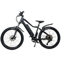
Find the device manual for free Pathfinder 500 Magnum in PDF.


| Product Type | Electric Bicycle (E-bike) |
| Brand | Magnum |
| Model | Pathfinder 500 |
| Motor Type | 48V, 500W Rear Geared Hub Motor |
| Battery | 48V, 13Ah, 624Wh Li-NCM |
| Display | Bigstone H102 |
| Throttle | Twist Throttle |
| Pedal Assist Sensor | Cadence Sensor (Speed mode) |
| Max Speed (PAS) | Up to 25 mph (configurable Class 1/2/3) |
| Max Speed (Throttle) | Up to 20 mph |
| Max Load Capacity | 265 lbs |
| Wheel Size | 20" |
| Tire Size | 20" x 3" |
| Brakes | Hydraulic Disc Brakes |
| Derailleur | Shimano Altus, 7-speed |
| Freewheel | 7-speed |
| Fork | Rigid |
| Lights | Integrated front and rear, controlled from display |
| Kickstand | Included |
| Charging Temperature Range | 32°F to 140°F (0°C to 60°C) |
| Warranty | Limited, register at www.magnumbikes.com/warranty |
| Recommended Tools | Allen wrenches, wrench for pedals, torque wrench |
| Manual Pages | 22 |
Frequently Asked Questions - Pathfinder 500 Magnum
User questions about Pathfinder 500 Magnum
0 question about this device. Answer the ones you know or ask your own.
Ask a new question about this device
Download the instructions for your Electric bike in PDF format for free! Find your manual Pathfinder 500 - Magnum and take your electronic device back in hand. On this page are published all the documents necessary for the use of your device. Pathfinder 500 by Magnum.
USER MANUAL Pathfinder 500 Magnum
PLEASE READ ME FIRST
1. General Introduction
1.1 Welcome 01
1.2 Use of Manual 01
1.3 Service and Technical Support 01
1.4 Bike Components 01
1.4.2 E-Bike 02
1.5 Technical Data 03
2. Assembly and Adjustment
2.1 Handlebar and Stem Assembly 04
2.2 Assembly of the Pedals 05
2.3 Seat Position 06
2.4 Saddle Height 07
2.5 Saddle Adjustment 07
3. Battery and Charger
3.1 Overview 08
3.2 General Remarks 08
3.3 Installing and Removing the Battery 08
3.4 Charging 08
4. Display 09
5. Recommendations and Maintenance
5.1 General Requirements 15
5.2 Maintenance Schedule 16
5.3 Definition of Tampering and Recommendations 17
6. Warranty 18
1. General Introduction
1.1 Welcome
Thank you for purchasing a Magnum electric bike, and welcome to the Magnum Bikes family of e-bike enthusiasts. We encourage you to join our Facebook group “Magnum Bikes Community”. Our Facebook group is a place for Magnum riders to ask questions, have discussions, share recommendations and experiences and connect with other Magnum Bike enthusiasts. You can find the group linked here: https://www.facebook.com/groups/389290978573773
1.2 Use of Manual
We encourage you to read this manual thoroughly before you take your new E-bike for a ride. It is essential not to overlook the safety instructions and explanations of both traditional and non-traditional bike parts. So please take a moment to read through the various sections before you get in the saddle.
1.3 Service and Technical Support
This manual is intended as a general overview of your new E-bike, and is therefore not an extensive reference. Please consult your local Magnum dealer or Magnum customer support team for technical support, including information about service, maintenance, and repairs. In addition, you can visit our website (www.magnumbikes.com) for more information about our products and technology or find a dealer close to you.
*Disclaimer
Because it is impossible to anticipate every situation or condition which can occur while riding, this manual makes no representations about the safe use of bicycles under all conditions. There are risks associated with the use of any bicycle which cannot be predicted or avoided, and which are the sole responsibility of the rider. You should keep this manual along with any other documents that were included with your bicycle. All content in this manual is subject to change without notice. Magnum Bikes makes every effort to ensure accuracy of its documentation and assumes no responsibility of liability if any errors or inaccuracies appear within. Assembly and initial adjustments of your Magnum e-bike requires special tools and skills. It is recommended that this be done by a trained bicycle mechanic if possible.
1. General Introduction
1.4 E-Bike

-
Rear Light 8. Rear Disk Brake 15. Chain 22. Front Fender
-
Rear Fender 9. Water Bottle Mount 16. Pedal 23. Wheel Reflector
-
Motor 10. Saddle 17. Crankset 24. Front Fork
-
Freewheel 11. Seatpost 18. Controller 25. Dropout + Skewer
-
Rear Derailleur 12. Saddle Quick Release 19. Front Disc Brake 26. Tire
-
Chain Guard 13. Battery 20. Adjustable Stem
-
Carrier
-
Kickstand
-
Front Light

-
Left Brake Lever
-
Right Brake Lever
-
Left Grip
-
Right Grip
-
Display Controller 8. Throttle
-
Display
-
Bell
-
Adjustable Stem
-
8-Speed Thumb Shift
1. General Introduction
1.5 Technical Data
| Component | |
| Motor 48V, 500W | Rear Geared Hub Motor |
| Battery 48V, 13Ah, 624Wh Li-ncm | |
| Display Bigstone | H102 Display |
| Throttle Twist Throttle | |
| Front Fork Rigid | Fork |
| Brake Levers Left and Right | |
| Brakes Hydraulic | Disc Brakes |
| Derailleur Shimano, Altus, 7-speed | |
| Freewheel 7-speed | |
| Wheel / Tire 20" / 3" | |
| Front Light Integrated and controlled from the display | |
| Rear Light Integrated and controlled from the display | |
| Max Loading 265lbs | |
| Max Speed 2 Cadence sensing PAS up to 25mph, throttle up to 20mph | |
| 2 Can be configured to class 1, 2, or 3 e-bike | |
2. Installation and Adjustment
2.1 Handlebar and Stem Assembly

- Loosen the screws on the faceplate of the stem. Remove the faceplate and set aside.
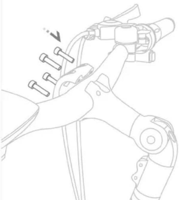
- Center the handlebar and put the faceplate back in place. Tighten the 4 faceplate screws in a star pattern.
Handlebar & Stem Adjustment
To adjust the angle of your stem loosen the stem bolt (1).

2. Installation and Adjustment
2.2 Assembly of the Pedals
Identify your pedals: check the letters on the pedals, "L" or "R".
Right and left are the same as when you are riding the bike. The "R" and "L" marked pedals are for the right and lefts sides of the bike as if you were riding it.
The "R" marked pedal is for the right, thread it into the crank clockwise and tighten.
The "L" marked pedal is for the left., thread it into the crank counterclockwise and tighten.

WARNING
First screw on the pedals by hand, then tighten with the wrench provided.


2. Installation and Adjustment
2.3 Seat Position

To enable comfortable, fatigue-free and safe riding, the saddle and handlebar height should be adjusted to the body size of the rider.
The saddle height is correct if the leg is near full extension while the foot is resting flat on the pedal in the bottom position of the crank cycle. The toes must still be able to touch the ground comfortably.


Optimal
2. Installation and Adjustment
2.4 Saddle Height
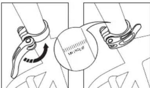
The quick-release lever must require noticeable effort to put into fully closed position to prevent any undesired movement while riding.
WARNING
An improperly closed quick release lever can open again or have limited ability to keep the saddle in place. This may cause the saddle to suddenly drop into the seat tube, potentially leading to serious falls and injury.
There is a minimum insertion line marked on the seat post (failure to observe the minimum insertion line can result in serious injury); please ensure the seat post is always inserted into the seat tube beyond this line (the line must be inside the seat tube).
Loosen the quick release lever at the top of the seat tube, determine the appropriate saddle height and tighten the clamp.
The clamping force can be adjusted by adjusting the bolt on the quick release lever.
The quick release lever must be closed with considerable counter pressure.
3.Battery and Charger
3.1 Overview
A Battery
B Power Button
C Power Indicator
D Charging Port
⚠ WARNING


Please ensure that the battery is locked in place before use
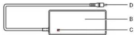
A AC Plug 1
B Charger
C Charging Indicator
D Battery Plug

3.2 General Remarks
Stop charging the battery immediately if you notice anything unusual, such as smoke or a strange smell; take out the battery and store it outside of the house, then take the battery to an authorized dealer or experienced technician for service or replacement.
In the unlikely case that the battery catches fire, do NOT attempt to put it out with water. Use sand or another fire retardant instead and call emergency services immediately.
3.3 Installing and Removing the Battery
Turn the lock (2) clockwise to unlock the battery, then grip firmly and pull from the bottom of the battery (1) to remove it from the bike.
Insert the top of the battery into the frame first and then carefully push the bottom of the battery into the frame until it clicks securely into place.
Remove the key from the lock (2). Ensure that the battery is well secured

3.4 Charging
Charging at temperatures below 32° F ( 0° C) or above 140° F ( 60° C) can cause the battery to charge insufficiently and can be harmful to the life of the battery.
During charging, the charger's LED light will be continuously red.
Charging is completed when the charger's LED turns green.
Do not leave your battery charging overnight.
Please use the original charger or a certified replacement charger from Magnum Bikes.
The charger lights up in red during charging, and turns green when fully charged. Unplug the charger once the battery is full.
Close the rubber charging port on the battery to protect the battery.
4. Display
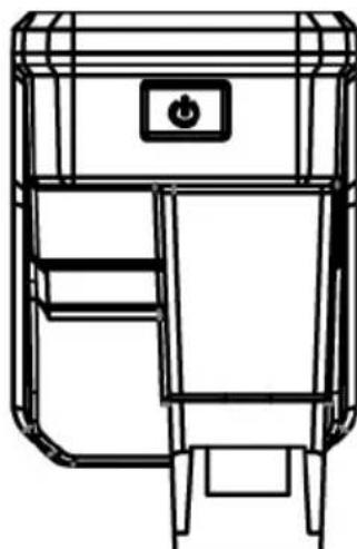
Appearance

Powering ON/OFF
Press and hold the power button (located above the top of the display screen) to turn on the display.
4. Display
Indicators & Buttons

Display Indicators
1 Speed of rider
2 Speed units chosen in the display settings
3 Displays when walk mode is in use
4 Displays when the lights are turned on
5 Displays the active level of pedal assist
6 Shows battery power left
7 Indicates if ODO, Trip, or Range is showing

4.Display
Power On/Off
Turn the battery ON, then press and hold the power button to turn the display ON.
Press and hold the power button to turn the display OFF.
Pedal Assist Level
Press the increase arrow button to increase the level of pedal assist.
Press the decrease arrow button to decrease the level of pedal assist.
The level of pedal assist will show on the display as it is increased or decreased by the rider.
The assist levels do not cycle. Meaning that you can increase up to the top level of pedal assist and then must decrease back down to 0 level pedal assist.
Enter/Exit Walk Mode
Press and hold the decrease arrow button to enter walk mode.
The walk mode indicator will appear on the display to show that walk mode is active.
When the decrease arrow button is released walk mode will stop.
Switching Trip, ODO, and Range
While the display is ON and in it's regular interface press and release the power button to switch from Trip, ODO, and Range.
4.Display
Display Settings
Enter/Exit The Display Settings Menu
Press the power button and increase arrow button at the time to enter the display settings menu.
Press the power button and decrease arrow button at the same time to exit the display settings menu.
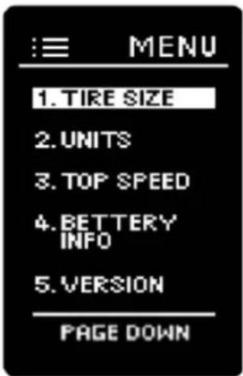
Display Settings Menu Navigation
Use the increase and decrease arrow buttons to move through the display settings menu.
After the menu item is highlighted, press the power button to open the options.
To see the next menu page press the power button when "Page Down" is highlighted.
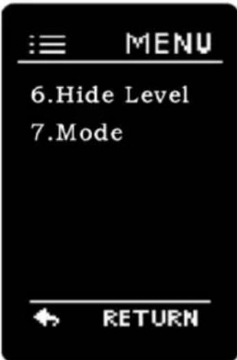
Tire Size
If tire size is not pre-set - select your wheel/tire size and press the power button to set your option.

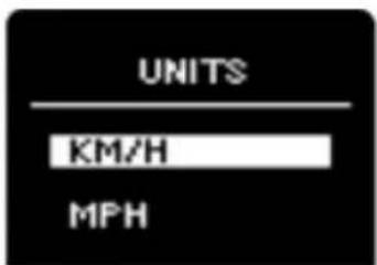
Speed Units
Select km/h or mph and press the power button to set your option.
Top Speed Setting
Top speed is pre-set and can only be adjusted by entering the password. Consult a certified Magnum Bikes dealer or Magnum Bikes customer support if you need further assistance with your speed settings.
Battery Information
Battery information will not show in the display settings on this bike model.
System Version
This option cannot be changed but will display the hardware and software version of the display.

Mode Setting
This setting refers to the pedal assist sensor.
If you have a cadence sensor this setting should be set to "speed".
If you have a torque sensor this setting should be set to "torque".
Magnum "Pathfinder" will come with a cadence sensor. The Magnum "Pathfinder T" will come with a torque sensor. The T stands for torque.

Trip Reset
Press and hold the increase arrow and decrease arrow buttons at the same time for 2 seconds to clear the single trip mileage.

5. Recommendations and Maintenance
5.1 General Requirements
E-bikes use metal shells to cover the electric components, we strongly advise against the use of excessive water to wash the shells and parts around them. Use a soft cloth with a neutral solution to wipe the dirt off the shells. Afterward, wipe everything dry with a clean soft cloth.
Do not use high-pressure water or air hoses for cleaning; this can force water into electrical components, which may cause malfunctioning.
Do not wash plastic components with excessive water. When the internal electrical parts are affected by water the insulator may corrode, leading to power-drain or other problems.
Do not use soap solutions to wash the metal components. Non-neutral solutions may cause discoloration, distortion, scratching, etc.
Avoid leaving the bike outdoors
When not riding, keep the bike in a location where it will be protected from snow, rain, sun, etc. Snow and rain can cause the bike to corrode. Ultraviolet rays from the sun can cause unnecessary fading of paint or crack any rubber or plastic on the bike.
| Recommended Torque Values | |
| Handlebar 8-10 Newton Meters | |
| Stem 8-10 Newton Meters | |
| Saddle 18-20 Newton Meters | |
| Front Wheel 16-25 Newton Meters | |
| Rear Wheel 35-40 Newton Meters | |
| Bottom Bracket Parts 35-55 Newton Meters | |
| Pedals 35 Newton Meters | |
| Rotor Bolts 6 Newton Meters | |
| Disk Caliper Mount 10 Newton Meters | |
| Crank Bolts 40 Newton Meters | |
| Rear Derailleur Cable Pinch 6 Newton Meters | |
| Front Derailleur Clamp 7 Newton Meters | |
| Saddle Post Clamp 7 Newton Meters | |
5.2 Maintenance Schedule
To keep your E-bike in optimal condition and your riding experience at its most enjoyable, we strongly recommend following the suggested maintenance schedule. You should study it and allow it to become second nature to your riding.
| Maintenance Schedule Each Ride Weekly Monthly 6 Months Yearly | ||||
| Tire Pressure X | ||||
| Tire Condition X | ||||
| Visual Inspection X | ||||
| Brake Lever Pressure X | ||||
| Quick Releases X | ||||
| Handlebar Alignment X | ||||
| Saddle Alignment X | ||||
| Battery Pack Locked X | ||||
| Wheel Check X | ||||
| Inspect Frame Condition1 X | ||||
| Clean & Lubricate Chain X | ||||
| Check Brake Pads | X | |||
| Lubricate Forks | X | |||
| Lubricate Brakes & Cables | X | |||
| Lubricate Folding Mechanism | X | |||
| Check all Bolts & Torque Settings | X | |||
| Clean Bicycle | X | |||
| Charge Battery | X | |||
| Check Heel Spokes | X | |||
| Inspect Rim Condition | X | |||
| Inspect Saddle, Rails & Clamp | X | |||
| Grease Pedal Bearings | X | |||
| Check Hub Bearings | X | |||
| Check Headset Bearings | X | |||
| Check Bottom Bracket Bearings | X | |||
| Replace Brake Pads | X | |||
| Replace Brake Cables2 | X | |||
| Replace Tires2 | X | |||
| 1 include welds for fissures, 2 depends on use | ||||
⚠ Warning
As with all mechanical components, electrically power assisted cycles (EPAC) are subjected to wear and high stresses. Different materials and components may react to wear or stress fatigue in different ways. If the design life of a component has been exceeded, it may suddenly fail, possibly causing injuries to the rider. Any form of crack, scratches or change of coloring in highly stressed areas indicate that the life of the component has been reached and it should be replaced.
5.3 Definition of Tampering and Recommendations
| Category 1 | |||
| Components which can only be replaced after approval from the bicycle manufacturer/ electronic system provider | |||
| Motor | Controller | Electric Cables | Battery |
| Sensors | Display Controls | Display | Battery Charger |
| Category 2 | |||
| Components which can only be replaced after approval from the bicycle manufacturer | |||
| Frame Hub-motor Wheel | Brake Pads Bottom Bracket | ||
| Fork Brake System Rear Carrier | |||
| Category 3 | |||
| Components which can only be replaced after approval from the bicycle or component manufacturer | |||
| Cranks Wheel without Hub Motor Tires Brake System | |||
| Chain | Belt Rim Tape Mechanical Brake Cables Handlebar | |||
| Seat Post Saddle Hydraulic Brake Cables Stem | |||
| Category 4 | |||
| Components which can be replaced without approval | |||
| Headset | Inner Tubes | Shifting Housing & Cables | Kickstand |
| Pedals | Chainring | Cassette | Freewheel | Grips |
| Derailleurs | Front & Rear Lights | Wheel Reflectors | Front Reflector |
| Shifters | Mudguards | Fenders | Spokes | Rear Reflector |
⚠ Warning
Modifications to any part of your bike, such as the fork or frame, may make that part or the entire bike unsafe. A poorly installed or modified component can increase the stress on all other parts, greatly increasing their chance of failure. Modifications can also adversely affect the handling of your bike, resulting in loss of control, falls and serious injury. Please do not add, remove, or modify parts of your bike in any way before consulting with a trained bike technician. We recommend you consult with us before you make modifications or add parts, in order to confirm their safety and compatibility with your bike.
6. Warranty
Your Magnum E-bike comes with a limited warranty. Please visit www.magnumbikes.com or your local Magnum dealer for details.
Bike must be registered at www.magnumbikes.com/warranty in order to be covered by the one year warranty.
Stay Connected

@magnumbikes @magnumelectri bikes

@magnumbikes @magnumbikes


www.magnumbikes.com @magnuides

info@magnumbikes.com 323.375.2666
magnum ELECTRIC BIKES

- GENERAL INTRODUCTION
- ASSEMBLY AND ADJUSTMENT
- BATTERY AND CHARGER
- RECOMMENDATIONS AND MAINTENANCE
- 1.1 WELCOME
- 1.2 USE OF MANUAL
- 1.3 SERVICE AND TECHNICAL SUPPORT
- DISCLAIMER
- 1.4 E-BIKE
- 1.5 TECHNICAL DATA
- INSTALLATION AND ADJUSTMENT
- 2.1 HANDLEBAR AND STEM ASSEMBLY
- HANDLEBAR & STEM ADJUSTMENT
- 2.2 ASSEMBLY OF THE PEDALS
- WARNING
- 2.3 SEAT POSITION
- 2.4 SADDLE HEIGHT
- 3.BATTERY AND CHARGER
- 3.1 OVERVIEW
- ⚠ WARNING
- 3.2 GENERAL REMARKS
- 3.3 INSTALLING AND REMOVING THE BATTERY
- 3.4 CHARGING
- DISPLAY
- POWERING ON/OFF
- DISPLAY INDICATORS
- 4.DISPLAY
- POWER ON/OFF
- PEDAL ASSIST LEVEL
- ENTER/EXIT WALK MODE
- SWITCHING TRIP, ODO, AND RANGE
- ENTER/EXIT THE DISPLAY SETTINGS MENU
- DISPLAY SETTINGS MENU NAVIGATION
- TIRE SIZE
- SPEED UNITS
- TOP SPEED SETTING
- BATTERY INFORMATION
- SYSTEM VERSION
- MODE SETTING
- TRIP RESET
- 5.1 GENERAL REQUIREMENTS
- AVOID LEAVING THE BIKE OUTDOORS
- 5.2 MAINTENANCE SCHEDULE
- 5.3 DEFINITION OF TAMPERING AND RECOMMENDATIONS
- WARRANTY
- STAY CONNECTED
- MAGNUM ELECTRIC BIKES
Brand : Magnum
Model : Pathfinder 500
Category : Electric bike