6405 - Network card / adapter Aruba - Free user manual and instructions
Find the device manual for free 6405 Aruba in PDF.


| Product Type | Modular Network Switch |
| Model | Aruba 6405 (SKU: R0X26A) |
| Chassis Form Factor | 7U, 19-inch rack-mountable |
| Dimensions (W x H x D) | 442.6 mm x 306.6 mm x 592.5 mm (17.4 in x 12.1 in x 23.3 in) |
| Weight (Empty / Fully Loaded) | 21 kg (45 lbs) / 61 kg (133 lbs) |
| Line Module Slots | 5 (numbered 3-7) |
| Management Module Slots | 2 (dual redundant, active/standby) |
| Power Supply Slots | 4 |
| Supported Power Supplies | 1800W (R0X35A) or 3000W (R0X36A), hot-swappable |
| Fan Trays | 2 hot-swappable, each with 4 fixed fans |
| Cooling Airflow | Front-to-rear, minimum 30 cm (11.8 in) clearance front and rear |
| Operating Temperature | 0°C to 45°C (32°F to 113°F) up to 5000 ft; derate 1°C per 1000 ft above |
| Operating Humidity | 15% to 95% at 45°C, non-condensing |
| PoE Support | Up to Class 6 (60W) per port on compatible line modules |
| Switching Capacity | Up to 1.2 Tb/s per line module (depending on module type) |
| Management Ports | 1x OOBM (10/100/1GbE), 1x RJ-45 console, 1x USB-C console, 1x USB-A |
| Redundancy | N+N or N+1 power redundancy, dual management modules, hot-swappable fans |
| Mounting Options | Two-post rack (included brackets) or optional four-post rack kit (R0X37A) |
| Safety Compliance | UL 60950-1, CSA 22.2, EN 60950-1, IEC 62368-1, Class 1 Laser |
| Included Accessories | Rack mounting brackets, cable manager, ESD wrist strap, documentation |
| Warranty | See Hewlett Packard Enterprise standard warranty |
Frequently Asked Questions - 6405 Aruba
User questions about 6405 Aruba
0 question about this device. Answer the ones you know or ask your own.
Ask a new question about this device
Download the instructions for your Network card / adapter in PDF format for free! Find your manual 6405 - Aruba and take your electronic device back in hand. On this page are published all the documents necessary for the use of your device. 6405 by Aruba.
USER MANUAL 6405 Aruba
Aruba 6400 Switch Series Installation and Getting Started Guide
aruba
a Hewlett Packard Enterprise company
Part Number: 5200-6596a
Published: May 2020
Edition: 2
Notices
The information contained herein is subject to change without notice. The only warranties for Hewlett Packard Enterprise products and services are set forth in the express warranty statements accompanying such products and services. Nothing herein should be construed as constituting an additional warranty. Hewlett Packard Enterprise shall not be liable for technical or editorial errors or omissions contained herein.
Confidential computer software. Valid license from Hewlett Packard Enterprise required for possession, use, or copying. Consistent with FAR 12.211 and 12.212, Commercial Computer Software, Computer Software Documentation, and Technical Data for Commercial Items are licensed to the U.S. Government under vendor's standard commercial license.
Links to third-party websites take you outside the Hewlett Packard Enterprise website. Hewlett Packard Enterprise has no control over and is not responsible for information outside the Hewlett Packard Enterprise website.
Chapter 1 About this document....6
Applicable products....6
Latest version available online....6
Related publications....6
Chapter 2 Installation precautions and guidelines....8
Space....11
Chapter 3 Site preparation....12
Safety recommendations....12
Electricity safety....12
Handling safety 12
Preventing electrostatic discharge damage 13
Laser safety....14
Examining the installation site....14
Temperature 14
Humidity....14
Cleanliness 15
EMI 15
Grounding....16
Power 17
Cooling 18
Product weight support....19
Recommended screwdrivers for switch installation....19
Shipping a rack-mounted Aruba 6400 switch chassis....19
Chapter 4 Introducing the Aruba 6400 switch series....21
Overview of the Aruba 6400 switch....21
Front of the switch 22
Management module (MM) slots 24
Power supply units (PSUs) and slots 27
Line module (LM) slots 28
Power cords and inlet adapters 33
Rear of the switch....33
Fan trays 34
Rear panel LEDs 35
Power cords, power inlet accessories, and power supplies....35
Power cord information 36
1800W PSU C15 Power cord information 36
3000W PSU C19 Power cord information....37
Power over Ethernet (PoE) operation 39
Switch software features 40
Chapter 5 Unpacking, lifting, and moving the chassis....41
Unpacking the switch components 41
Power cord information 42
Attaching an ESD wrist strap....42
Removing installed components from the chassis....43
Remove installed power supply units....44
Remove any installed line modules....45
Remove the fan trays....46
Move the chassis to the mounting location....47
Manually moving the chassis....47
Using a mechanical lift to move the chassis....48
Chapter 6 Mounting the switch....50
(Optional) Installing the chassis in a non-rack mounted position....50
Manually positioning the chassis on a non-rack mount surface....50
Using a mechanical lift to position the chassis on a non rack mount surface....51
Mounting the chassis in a rack 51
Shipping a rack-mounted Aruba 6400 switch chassis....51
Two-post rack mounting....52
Preparing the chassis for a two-post rack mounting.... 52
Manually mounting the chassis in a two-post rack 55
Using a mechanical lift to mount the chassis in a two-post rack....57
Four-post rack mounting....58
Preparing the chassis for an optional four-post rack mount....58
Grounding the chassis....67
Chapter 7 Installing components....69
Protect the switch and components from damage caused by ESD (Electrostatic discharge)....69
Installing a new power supply unit and AC inlet accessory in an empty slot....70
Install management modules in slots 1 and 2....73
Install line modules....74
Installing or removing transceivers....75
Installing a fan tray in an empty fan tray slot....76
Installing the cable manager....77
Chapter 8 Activating the switch....80
Power-on and boot-up....80
Initial management access....80
Chapter 9 Adding or replacing switch components....81
Protect the switch and components from damage caused by ESD (Electrostatic discharge)....81
Adding or replacing line modules with controlled shutdown or hot swap methods....82
Using controlled shut down to add or replace line modules....82
Adding a line module to an empty, unconfigured slot 82
Removing or replacing a line module....82
Removing or replacing a standby management module....84
Removing or replacing an active management module....86
Replacing a fan tray....87
Chapter 10 Troubleshooting....91
Protect the switch and components from damage caused by ESD (Electrostatic discharge)....91
Basic troubleshooting tips....92
Functions of the management module reset button....92
Chapter 11 Specifications....94
PSU output ratings....94
System power consumption....94
Aruba 6400 switch acoustics information....96
Aruba 6400 product weights....97
Product dimensions....97
Chapter 12 Safety and regulatory information....98
Chapter 13 Websites.... 100
Chapter 14 Support and other resources....101
Accessing Aruba Support....101
Accessing updates....101
Warranty information....102
Regulatory information....102
Documentation feedback......102
This document is intended for network administrators and support personnel.

NOTE: The switch prompts used in this document are examples and might not match your particular switch or environment.
The switch and accessory drawings in this document are for illustration only, and may not match your particular switch and accessory products.
Applicable products
Base Product SKU Description
R0X26A Aruba 6405 Switch
ROX27A Aruba 6410 Switch
ROX31A Aruba 6400 Management Module
ROX32A Aruba 6400 Fan Tray
R0X35A Aruba 6400 1800W Power Supply with C16 Inlet Accessory
R0X36A Aruba 6400 3000W Power Supply with C20 Inlet Accessory
R0X37A Aruba 6400 4-post Rack Mount Kit (Optional)
ROXnnA All Aruba 6400 Line Modules
R0X26A and R0X27A include rack mounting brackets and cable management components used for two-post rack mount or used with optional four-post rack or cabinet mount kit.
Latest version available online
Updates to this document can occur after initial publication. For the latest versions of product documentation, see the links provided in the Websites chapter of this document or visit the Aruba Support Portal at https://asp.arubanetworks.com/downloads.
Related publications
• START HERE: Installation, Safety, and Regulatory Information for the Aruba 6400 Switches and Accessories
• START HERE: Installation, Safety, and Regulatory Information for the Aruba 6400 Power Supplies
- START HERE: Aruba 6400 Switch Series Management Module
• Aruba 6400 Switch Series - Unpacking Information
• Transceiver Guide
• Fundamentals Guide
- Monitoring Guide
- Other ArubaOS-CX User Guides
For the latest version of this guide or any other Aruba 6400 publication, visit https://asp.arubanetworks.com/downloads.
Using a mechanical lift to raise, lower, and move the Aruba 6400 chassis is the recommended best practice. If a mechanical lift is used, ensure that the configured weight does not exceed the maximum load capacity of the lift.
Install any uninstalled components after mounting the switch.
Figure 1: Aruba 6405 five-slot switch weight warning
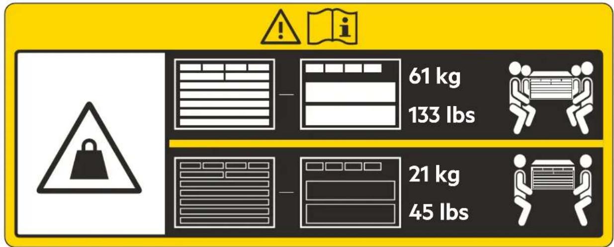
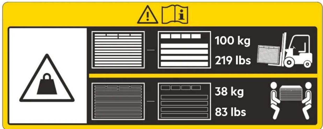
Figure 2: Aruba 6410 ten-slot switch weight warning
WARNING:
- To reduce the risk of personal injury or damage to equipment: ,
- Heed all warnings and cautions throughout the installation instructions.
If you plan to re-ship the switch in its original packaging, remove any transceivers installed in line modules before preparing the switch for shipment. See also Shipping a rack-mounted Aruba 6400 switch chassis.
- Observe local occupational health and safety requirements and guidelines for manual material handling.
The switch is heavy. Avoid personal injury due to the combined weight of the chassis and installed accessories. If your installation process includes manually lifting or carrying the switch instead of using a mechanical lift, uninstall the removable accessories from the switch before moving it. This guide includes information about removing and installing accessories, as well as the weight of the switch and individual accessories.
- Mount devices installed in a rack or cabinet as low as possible. Install the heaviest devices at the bottom and progressively lighter devices above.
- To prevent the rack or cabinet from becoming unstable and/or falling over, ensure that it is adequately secured.
- Ensure that the rack or cabinet unit in which you plan to mount the 6400 switch is rated to support the full equipment load you plan to install in the unit.
- Before you power up the switch, ground it reliably. See Grounding the chassis.
- Never have more than one power supply or module slot uncovered at a time while the switch is powered on. Install a blank slot cover on any empty management module, line module, power supply, or AC inlet slot opening in the chassis. This ensures the flow of cooling air through the chassis. It also helps to contain radio frequency emissions that may interfere with the operation of other devices.
- Replace only one fan tray at a time. Removing more than one fan tray at a time compromises system cooling, risks damage to the hardware, and can cause the switch to shut down abruptly. When replacing (hot-swapping) a fan tray, complete the process within two minutes. Allowing the switch to operate longer with only one working fan tray (6405) or three working fan trays (6410) installed reduces the flow of cooling air through the switch chassis and will result in the switch shutting down. For more information on fan trays, see Installing a fan tray in an empty fan tray slot.
- To avoid electrical and mechanical hazards, never allow any part of your body, jewelry, tool, or other foreign object to enter any module or power supply slot.
- The switch may use more than one power supply cable. To fully power down the switch, you must disconnect all power supply cables from the switch.

CAUTION:
- Protect the switch and its components from damage caused by ESD (Electrostatic discharge):
• See the ESD information under Preventing electrostatic discharge damage.
•Always wear an ESD wriststrap when handling the switch or its components. Ensure the strap is reliably grounded when installing or removing switch components.
- Hold management modules and line modules by their edges. Do not touch any electronic components or printed circuitry.
- Store uninstalled modules in antistatic bags.
- Do not ship the Aruba 6400 Series switch mounted in a rack without first checking for rack requirements and restrictions. Otherwise, damage to the switch or components may occur. Damage resulting from using unsupported methods or equipment to ship a rack-mounted chassis may void the switch warranty. For more information, see Shipping a rack-mounted Aruba 6400 switch chassis
- Ensure the source circuits for your 6400 Series switch are properly grounded. Connect the switch to the power sources by using the power cords supplied with the switch or power supply units.
- Only Aruba-approved power cords may be used with Aruba devices. See the power cord documentation provided in the latest version of the Aruba 6400 Switch Series Installation and Getting Started Guide. Lost or damaged power cords must be replaced only with Aruba-approved power cords.
- If your installation requires different power cords than the ones supplied with the switch or power supplies, be sure that the cords are adequately sized for the current requirements. In addition, be sure to use power cords displaying the mark of the safety agency that defines the regulations for power cords in your country/region. The mark is your assurance that the power cord can be used safely with the switch and power supply. For more on power cords, see Power cords, power inlet accessories, and power supplies.
- When installing the switch, select AC outlets near the switch for easy access in case the switch must be powered off.
- Do not install the switch in an environment where the operating ambient temperature exceeds its specification. (For environmental specifications, see Specifications.)
- Ensure that the switch does not overload the power circuits, wiring, and over-current protection. To determine the possibility of overloading the supply circuits, add the ampere ratings of all devices installed on the same circuit as the 6400 Series switch. Then compare the total with the rating limit for the circuit. The maximum ampere ratings are printed on the devices near their AC power connectors.
- Ensure that the air flow through the chassis is not restricted. Leave a front and rear clearance of at least 30 cm (11.8 inches) for air flow. Air flow direction is front-to-rear. (Fully perforated rack doors are acceptable within the 30 cm spacing.)
• Install a blank slot cover on any empty management module, line module, power supply, or AC inlet slot opening in the chassis. This ensures the flow of cooling air through the chassis. It also helps to contain radio frequency emissions that may interfere with the operation of other devices.
- If a power supply must be removed, and then reinstalled, wait at least 5 seconds before reinstallation. Otherwise, damage to the switch or its components may occur. The power supply needs this time to dissipate any retained power.
- For proper cooling, the 6405 switch requires two fan trays installed and the 6410 switch requires four fan trays installed. For more information on fan trays, see Fan trays.
- For rack-free mounting requirements and warnings, see Mounting the switch.
- Protect the equipment from AC power fluctuations and temporary interruptions with a regulating facility Uninterruptible Power Supply (UPS) device. This device protects the hardware from damage caused by power surges and voltage spikes, which keeps the switch in operation during a power failure.
Space
For easy installation and maintenance, make sure the rack has enough space to accommodate the switch and normal switch maintenance, such as installing or removing management modules, line modules, and fan trays. For dimensions, see Product dimensions.
Safety recommendations
To avoid possible bodily injury and equipment damage, carefully read the following publications before installing your Aruba 6400 Switch:
• Safety, Compliance, and Warranty Information (shipped with the switch)
- START HERE: Installation, Safety, and Regulatory Information for the Aruba 6400 Switches and Accessories (shipped with the switch)
- START HERE: Installation, Safety, and Regulatory Information for the Aruba 6400 Power Supply Units (shipped with the switch and with PSUs)
• All safety recommendations in this chapter
• The chapter titled Installation precautions and guidelines.

NOTE: The recommendations in the listed publications do not cover every possible hazardous condition.
Electricity safety
- Clear the work area of possible electricity hazards, such as ungrounded power extension cables, missing safety grounds, and wet surfaces or wet floors.
- Locate the emergency power-off switch in the room before installation so you can quickly shut power off if an electrical accident occurs.
- Remove all external cables, including power cords, before moving the chassis.
- Do not work alone when the switch has power.
Handling safety

CAUTION: Do not use the handle of a fan tray or a power supply unit, bezel, module locking or extraction levers, or the chassis air vents to lift or move the switch. Any attempt to move the switch with these parts may cause equipment damage and bodily injury.
When you move the switch, follow these guidelines:
- Remove all power supplies, line and management modules, fan trays, and all external cables, including the power cords, before moving the chassis.
- Use a minimum of four people to manually move a chassis weighing more than 100 lbs, and a minimum of two people to manually move a chassis weighing less than 100 lbs. To determine chassis weight, see Aruba 6400 product weights.

WARNING: Aruba recommends using a mechanical lift to move the chassis.
- Lift and lower the chassis slowly. Never move it suddenly.
For information and recommended practices for moving the chassis, see Unpacking, lifting, and moving the chassis.
Preventing electrostatic discharge damage
Be aware of the precautions you must follow when setting up the switch or handling components. A discharge of static electricity from a finger or other conductor may damage system boards or other static-sensitive devices. This type of damage may reduce the life expectancy of the switch or component.
To prevent electrostatic damage:
- Avoid hand contact by transporting and storing products in static-safe containers.
- Keep electrostatic-sensitive parts in their containers until they arrive at static-free workstations.
- Place parts on a grounded surface before removing them from their containers.
- Avoid touching pins, leads, or circuitry.
• Always use a properly grounded ESD wrist strap when touching static-sensitive components or assemblies.
Use one or more of the following methods when handling or installing electrostatic-sensitive parts:
- Use heel straps, toe straps, or boot straps at standing workstations. Wear the straps on both feet when standing on conductive floors or dissipating floor mats.
- Use conductive field service tools.
- Use a portable field service kit with a folding static-dissipating work mat.
- Use an ESD wrist strap connected to an ESD connection point on the switch (see the following image). Wrist straps are flexible straps with a minimum of 1 megohm ±10 percent resistance. To provide proper ground, wear the strap snug against the skin.
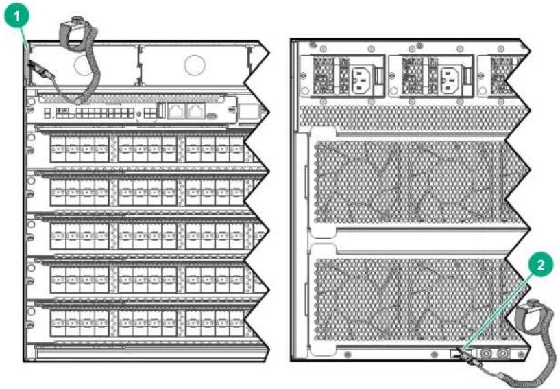
| 1 Remove the bezel and clip the alligator clamp onto the tab used to mount the bezel. |
| 2 Clip the alligator clamp onto the grounding lug. |
If you do not have any of the suggested equipment for proper grounding, have an Aruba authorized reseller install the part.
For more information on static electricity or assistance with product installation, contact an Aruba authorized reseller.
Laser safety

WARNING: Do not stare into any fiber port or view directly with non-attenuating optical instruments when the switch has power. The laser light emitted from the fiber port may injure your eyes.
The Aruba 6400 switches are Class 1 laser products.
Examining the installation site
The switch must be used indoors. To help ensure correct operation and a long service life for your switch, the installation site must meet the requirements in this section.
Temperature

CAUTION: If condensation appears on the chassis when you move it to a high-temperature environment, dry the chassis before powering it on to avoid short circuits.
To ensure correct switch operation, make sure the room temperature meets the following requirements.

NOTE: Above 1524m (5000ft), reduce maximum operating temperature by 1^ C ( 1.8^ F) per 305m (1000ft) altitude gain.
Table 1: Temperature requirements
| Temperature Range | |
| Operating temperature 0°C | to 45°C (32°F to 113°F) |
| Storage temperature -40°C | to +70°C (-40°F to +158°F) |
For more environmental information, see Environmental, safety, and electrical information.
Humidity
Maintain the humidity in your equipment room in the acceptable range, as described below.
- Lasting high relative humidity can cause poor insulation, electricity leakage, mechanical property change of materials, and metal corrosion.
- Lasting low relative humidity can cause ESD and circuit failure.
Table 2: Humidity requirements
| Humidity Range | |
| Operating humidity 15% to 95% | at 45C (104F), noncondensing |
| Storage humidity 15% to 95% | at 65C (149F), noncondensing |
Cleanliness
Dust buildup on the chassis might result in electrostatic adsorption, which causes poor contact of metal components and contact points. In the worst case, electrostatic adsorption can cause communication failure.
Table 3: Dust concentration limit in the equipment room
| Substance Concentration limit (particles/m3) |
| Dust particles ≤ 3 x 10⁴ (No visible dust on desk in three days) |

NOTE: Dust particle diameter ≥ 5 μm
The equipment room must also meet limits on salts, acids, and sulfides to eliminate corrosion and premature aging of components, as shown below.
Table 4: Harmful gas limits in the equipment room
| Gas Max. (mg/m3) | |
| SO_2 | 0.2 |
| H_2S 0.006 | |
| NH_3 | 0.05 |
| CI2 0.01 | |
EMI
All electromagnetic interference (EMI) sources, from outside or inside of the switch and application system, adversely affect the switch in the following ways:
• A conduction pattern of capacitance coupling.
- Inductance coupling.
• Electromagnetic wave radiation.
- Common impedance (including the grounding system) coupling.
To prevent EMI, use the following guidelines:
- If AC power is used, use a single-phase three-wire power receptacle with protection earth (PE) to filter interference from the power grid.
-
Keep the switch far away from radio transmitting stations, radar stations, and high-frequency devices.
-
Use electromagnetic shielding (for example, shielded interface cables) when necessary.
- To prevent signal ports from getting damaged by overvoltage or overcurrent caused by lightning strikes, route interface cables indoors only.
Grounding

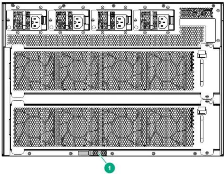
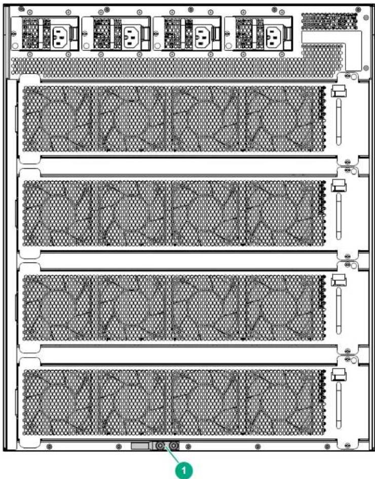
CAUTION: Reliably ground the switch to protect it from hazards such as lightning shocks, interferences, and ESD discharges. The switch is grounded through the safety wire in the power cords. Aruba recommends an independent grounding connection for the chassis if there is any doubt about the reliability of the grounding through the power mains. The grounding lug is located on the rear of the switch, at the bottom edge. This figure shows the grounding lug on the Aruba 6405 switch. On the Aruba 6410 is located in a similar position.
Figure 3: Grounding lug on the Aruba 6405 Switch
natural_image
Back view diagram of an electronic server rack with multiple drive bays and ventilation slots (no text or labels)1 Grounding lug
Figure 4: Aruba 6410 Switch grounding lug
natural_image
Back view of a server rack with multiple drive bays and ventilation grilles (no text or symbols visible)Make sure the resistance between the chassis and the ground is less than 1 ohm.
Power
Perform the following tasks to meet the power requirements:
Procedure
- Calculate the system power consumption. The system power consumption varies by module type and density. (See System power consumption.)
- Identify the number of power supplies. Include sufficient power to meet power consumption and sufficient redundancy to ensure system uptime in the event of a PSU failure.
- Verify that the power system at the installation site meets the requirements of the power supplies including the input method and rated input voltage. (For power supply unit (PSU) information, see System power consumption.)
Cooling
Plan the installation site for adequate ventilation:
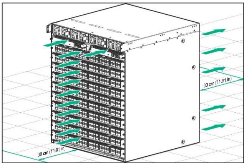
- Leave a minimum of 30 cm (11.81 in) of clearance at the front and rear of the switch. (Perforated rack doors are acceptable within the 30cm spacing.)

NOTE: Air flow into and out of the switch is indicated by the arrows in the image below.
- Ensure that the rack for the switch is well ventilated, with minimal airflow obstruction at the front and rear.
- The installation site HVAC system must be capable of removing all heat generated by the switch.
- Verify that the airflow design of the chassis is compatible with the airflow design of the installation site.
Figure 5: Aruba 6405 Switch cooling air flow
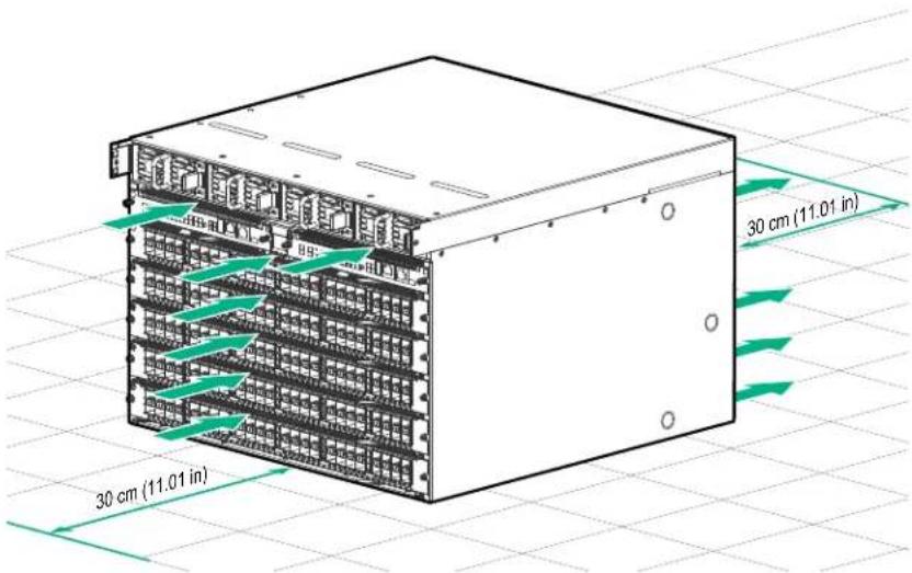
Figure 6: Aruba 6410 Switch cooling air flow
Product weight support
Make sure the floor can support the total weight of the rack, chassis, modules, power supplies, and all other components and devices. Take into consideration system expansions (for example, adding more modules and switches) when you plan the loading capacities.
For component weights, see Aruba 6400 product weights.
Recommended screwdrivers for switch installation
Recommended screwdrivers for switch installation
- Torx T10
•Securing management modules to the chassis
- Securing line modules to the chassis
- Securing fan trays to the chassis
- Torx T20
•Securing rack brackets to the chassis
- Torx T25
- Securing the cable manager to the rack
- Securing 4-column rack kit to the rack
- Securing ground lug to the chassis
• Phillips #3
- Securing 2-column rack kit to rack
- Securing the cable manager in a two-post rack installation
Shipping a rack-mounted Aruba 6400 switch chassis
Aruba supports shipping of rack-mounted Aruba 6400 switches where the rack or cabinet is:
- A Hewlett Packard Enterprise four-post rack product compatible with the R0X37A 4-post rack rail kit.
• Certified for integrated shipping.
- Mounted to a shock pallet.
- Mounted with the R0X37A 4-post rack rail kit, including the shipping support hardware.

NOTE: For information on Aruba rack products, visit https://www.hpe.com/us/en/product-catalog/servers/server-racks.hits-12.html.
Aruba does not support shipping rack-mounted Aruba 6400 switches in:
- Two-post racks
- Racks not certified for integrated shipping
- Racks not mounted on a shock pallet
• Racks not offered by Hewlett Packard Enterprise
• Hewlett Packard Standard Series racks

CAUTION: Shipping an Aruba 6400 switch chassis in a two-post rack is not supported and may result in damage to the switch or components. The Aruba warranty does not apply to products damaged or rendered defective as a result of using non-supported shipping methods.
- Install slot covers over any empty management module, line module, PSU slots, or AC inlet slots.
- Securely mount the switch in a compatible four-post rack or cabinet. Use the R0X37A 4-post Rack Rail Kit as described in this guide under Mounting the chassis in a rack. Include secure installation of the following shipping support hardware packed in the rack rail kit:
- Front (2-post) rack mounting brackets (shipped with the switch), HPE Parts Store part 5380-0439 (the 6410 switch ships with a quantity of two kits).
- Rear adapter plates and rack brackets.
For detailed mounting information, see Mounting the switch.

CAUTION: If you plan to re-ship the switch in its original packaging, remove any transceivers installed in line modules before preparing the switch for shipment.
Overview of the Aruba 6400 switch
The Aruba 6400 Switch Series is a modern, flexible and intelligent family of high availability modular switches ideal for use from access to core and into the data center.
A powerful distributed architecture supports scalable, non-blocking performance to future-proof your network for tomorrow's unpredictable demands. Versatile 5 and 10 slot chassis support speeds of up to 100GbE, high-power PoE, multi-gigabit Ethernet, and redundant management, power and fans for a highly available network.
A cloud-centric design with a fully programmable OS delivers automation and simplicity, including easy-to-use configuration tools for error-free installs. Built-in monitoring and analytics across the network provide operators with immediate troubleshooting and problem resolution insights.
Key features
- Compact five or ten slot units (7U and 12U) chassis models
• High performance, high-speed network - Multi chassis link aggregation group (LAG) for high availability
- High-speed connection with up to five line modules on the Aruba 6405 switch and up to ten line modules on the Aruba 6410 switch.
- Dual redundant management modules for hitless failover
- N+N redundant, hot swappable power slots
- REST API enables distributed or centralized orchestration
Physical dimensions, weight, and mounting
- Weight:
-6405 model:
- Empty configuration weight: 21 kg (45 lbs)
- Full configuration weight: 61 kgs (133 lbs)
-6410 model:
- Empty configuration weight (estimate): 38 kg (83 lbs)
- Full configuration weight (estimate): 100 kgs (219 lbs)
- Mountable on a 19" two post rack with included rack mounting brackets or an (optional) four post (R0X37A) rack rail kit
See Specifications for more information.
Switch configurations
The Aruba 6400 switch models are each available for order as a base bundle with an option to add management modules, line modules, and power supply units (PSUs). The following table lists the options available. For further information, contact your Aruba authorized sales representative and see the latest release notes for minimum software version necessary for each component.
| Product number | Product description |
| ROX31A Aruba | 6400 Management Module |
| ROX38B | Aruba 6400 48-port 1GbE Class 4 PoE Module |
| ROX39B | Aruba 6400 48-port 1GbE Class 4 PoE and 4-port SFP56 Module ^1 |
| ROX40B Aruba | 6400 48-port 1GbE Class 6 PoE and 4-port SFP56 Module ^1 |
| ROX41A Aruba | 6400 48-port HPE Smart Rate 1/2.5/5GbE Class 6 PoE and 4-port SFP56 Module ^1 |
| ROX42A Aruba | 6400 24-port 10GBASE-T and 4-port SFP56 Module ^1 |
| ROX43A Aruba | 6400 24-port SFP+ and 4-port SFP56 Module ^1 |
| ROX44A Aruba | 6400 48-port 10/25GbE SFP28 Module |
| ROX45A Aruba | 6400 12-port 40/100GbE QSFP28 Module |
| ROX35A Aruba | 6400 1800W Power Supply (includes an Aruba C16 AC inlet accessory) |
| ROX36A Aruba | 6400 3000W Power Supply (includes an Aruba C20 AC inlet accessory) |
1 50 Gigabit Ethernet capability for SFP56 ports available with a future software release.
To order optional accessories or replacement parts, contact your Aruba authorized sales representative.
Front of the switch
The front of the switch consists of:
- Four power supply unit (PSU) slots covered by the removable bezel (not pictured)
- Two management module slots
- Five line module slots for the Aruba 6405 chassis
- Ten line module slots for the Aruba 6410 chassis (not pictured)
The following figure indicates the location of the slots and modules on the switch.
Figure 7: Aruba 6405: front of the switch
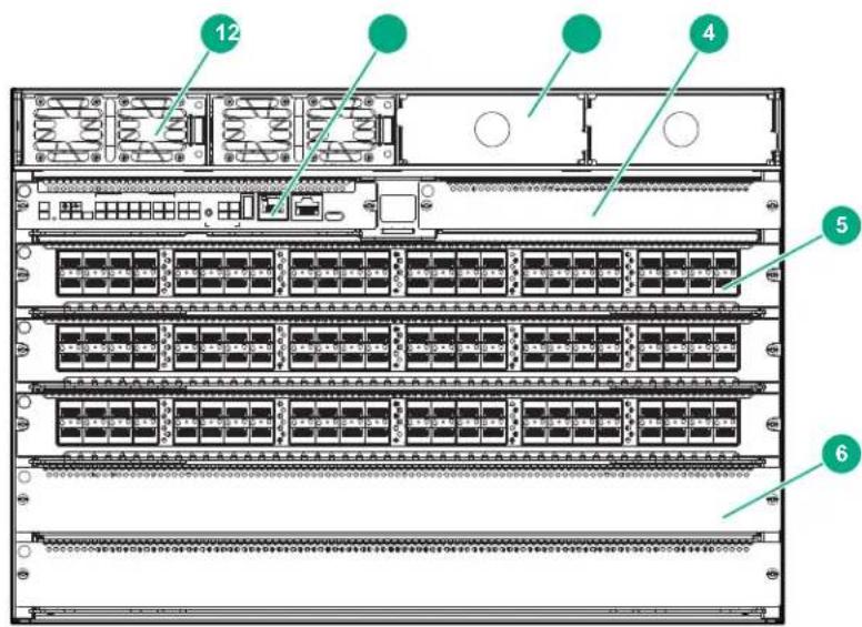
| 1 A power supply slot with power supply unit (PSU) installed |
| 2 A management module installed in a management slot |
| 3 An empty PSU slot with a slot cover in place |
| 4 An empty management module slot with a slot cover in place |
| 5 A single line module slot with line module installed |
| 6 An empty line module slot with a slot cover in place |
Management module (MM) slots
The Aruba 6400 switches have two management module (MM) slots. Management modules support control plane activities and in-memory running of the Time Series Database.
Figure 8: Management module slots with management modules installed
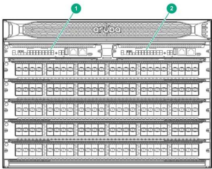
1 Aruba 6400 Management Module installed in slot 1
2 Aruba 6400 Management Module installed in slot 2
When two management modules are installed, one operates in active mode and the other operates in standby mode. The active slot is determined by election. Installing two management modules provides control plane high availability.
Figure 9: Management module features
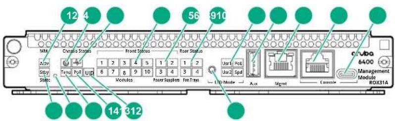
| 1 Mgmt state (Actv) LED | Indicates the status of the management module after booting. If the MM is the active MM, then the LED glows steady green. |
| 2 Chassis power LED | When the system is receiving power, glows steady green. |
| 3 Chassis health LED (green) | Indicates status of the switch. LED glows steady green when switch is ready after booting from the Network Operating System (NOS). |
| 4 Line module status LEDs Indicates if a line | module is installed in a line module slot (3 through 7 for 6405 switches; 3 through 12 on 6410 switches). If a line module is installed in a given slot, then the numbered LED for that slot glows steady green. |
| 5 Front Power supply status (1 2 3 4) LEDs | Indicates if a power supply is installed in the slot. If an active power supply is installed, then the LEDs glow steady green. |
| 6 Fan tray status LEDs (1 - 4) Indicate if the fan tray is installed in the slot. If a fan tray is installed in the slot, then the LED glows steady green. | |
| 7 LED mode: Usr1, Usr2, Spd, and PoE LEDs | The display of these LEDs is based on the LED mode button selection.·Usr1 LED: Indicates if the line module is working correctly.·Usr2 LED: Reserved·PoE: Indicates overall status of Power-over-Ethernet in the system.·Off: disabled or not currently delivering power.·On Green: Normal operation;·Slow Flash Orange: PoE fault condition. Use line module status LEDs and LED Mode to isolate the failure down to the line module and port level.·Spd LED: Indicates the traffic rate of the line module. |
| 8 Auxiliary port | Without a USB device installed, the auxiliary port LED is off after power-on and self-test.With a USB device installed, this LED displays the following after power-on and self-test:·Steady green: USB installed, initialized, and mounted, but no data transfer.·Flicker green: Data transfer in progress |
| 9 Mgmt port (OOBM Port) with Activity/Link LED | Without an active network connection, this LED is off after power-on and self-test completes.With an active network connection, this LED operates as follows:·Half-bright green: Port enabled and receiving Link indication from connected device.·Flickering half-bright to full-bright green: Varying port activity level.·Steady green: Port at high utilization. |
| 10 Serial console port (RJ-45) | |
| 11 USB-C console port | |
| 12 LED Mode button Changes the behavior of the line module port LEDs. This button changes the LED behavior from the default Link/Activity behavior to cycle through the PoE, speed (Spd), and user (Usr) options. | |
| 13 | Chassis Unit Identi cation (UID) LED Visual beacon to assist in quickly locating the unit. O = not activated. On Blue or Slow Flashing Blue = activated as system location aid. |
| 14 Chassis Power-over-Ethernet status (PoE) LED | Indicates the overall status of Power-over-Ethernet in the system.O = disabled or not currently delivering power.On Green = Normal operation.Slow Flash Orange = PoE fault condition; use Module status LEDs and LED Mode to isolate the failure down to line card and port level. |
| 15 Chassis temperature status (Temp) LED | Indicates the status of the chassis temperature. If the temperature is at or below the speci ed rating, then the LED glows steady green, |
| 16 Mgmt reset button A recessed button that is used to reboot the selected management module. | |
| 17 Mgmt state (Stby) LED Indicates the status of the management module after booting. If the MM is the standby MM, then the LED glows steady green. | |
Management module specifications
The key specifications of the management modules are:
• CPU: 4-core ARM Cortex-A72 operating at 1.8GHz
• 32GB eMMC ash memory
- DRAM: 1xRDIMM module with 16GB of DDR4 memory with ECC protection
- Ports and reset buttons:
•Out of band management port (OOBM): 10M/100M/1GbT with no EEE and no MACsec support
USB-A port: Used for USB mass storage and Bluetooth dongle. Supports up to 500 mA and up to USB 2.0 speed.
- Console ports (Only one console port is active at a time for user inputs):
- RS232 console port with RJ45 form factor
- USB-C console port
Management module LEDs
Chassis and module status LEDs:
• 1x Management module health LED
- 3x Mgmt State LEDs (includes one LED each for active and standby states).
• 1x chassis temperature status LED
- Front status LEDs:
-4x power supply status LEDs
-10x line card status LEDs
-2x management module status LEDs
- 4x line module port state LEDs (includes one LED to indicate port speed, one user LED to indicate line module port fault and two reserved LEDs).
- Rear status LEDs:
- 3x fan status LEDs (indicate status of the six fans in each fan tray).
Power supply units (PSUs) and slots
The Aruba 6400 has four power supply unit slots that support the R0X35A Aruba 6400 1800W Power Supply and the R0X36A Aruba 6400 3000W Power Supply.
Figure 10: Aruba 6400 3000W Power Supply (ROX36A)
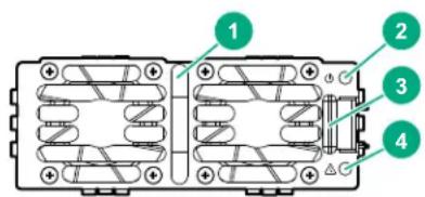
| 1 Power LED (green) |
| 2 Power fail LED (amber) |
| 3 Power supply handle |
| 4 Latch release tab |
- A single PSU is sufficient for fans and management cards to come up and provide user access and diagnostics.
- At 220V AC, only two PSUs are required for full operation and a single PSU is sufficient for the fans and management cards to come up and provide user access/diagnostics.
- Options for redundancy during configuration include n + n and n + 1 . As long as there is at least 2 PSUs in the chassis, n + 1 redundancy can be configured. With 4 PSUs, n + n redundancy can be configured.
-4 PSUs offers 2+2 or 3+1 redundancy
-3 PSUs offers 2+1 redundancy
-2 PSUs offers 1+1 redundancy
- At 110V AC: The switch offers N + N redundancy.
- The PSUs are hot swappable. The chassis can be connected to an AC power source for a given PSU slot while the PSU for that slot is being removed or installed.
PSU LEDs
There are two LEDs on a PSU to indicate PSU status:
• Power LED (green)
• Power fail LED (amber)
PSU bezel
Figure 11: PSU bezel
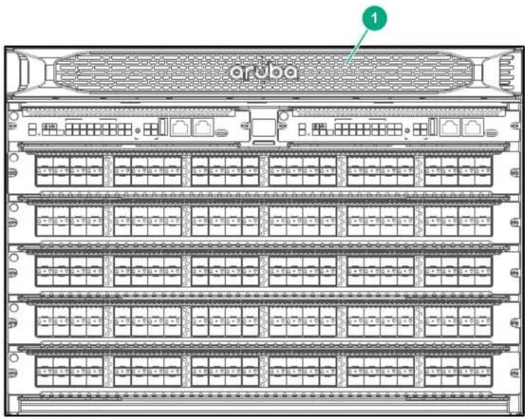
1 PSU bezel
The bezel hides the power supplies. Aruba recommends keeping the bezel in place except when removing or installing a power supply.
PSU slot cover
Aruba recommends installing and maintaining blank power supply slot covers in all empty PSU slots for optimal system thermal and cooling performance.
Line module (LM) slots
The Aruba 6405 switch has five line module (LM) slots and the 6410 switch has ten line module slots. The LM slots are numbered 3 through 7 for the 6405 switch and 3 through 12 for the 6410 switch.
Line module specifications
Table 5: Line module specifications - 100GbE through 40GbE
| Part# Maximum Band-width | 100 GbE 50 GbE | 1 | 40 GbE | |
| ROX38B (48p 1GbE CL4 PoE) | 48 Gb/s No No | No | ||
| ROX39B (48p 1GbE CL4 PoE 4SFP56) | 248 Gb/s No Rj | -45: No | SFP56: 50GbE accessories | No |
| ROX40B (48p 1GbE CL6 PoE 4SFP56) | 248 Gb/s No Rj | -45: No | SFP56: 50GbE accessories | No |
| ROX41A (48p SR5 CL6 PoE 4SFP56) | 440 Gb/s No Rj | -45: No | SFP56: 50GbE accessories | No |
| ROX42A (24p 10GT 4SFP56) | 440 Gb/s No Rj | -45: No | SFP56: 50GbE accessories | No |
| ROX43A (24p SFP+ 4SFP56) | 440 Gb/s No SFP+: No | SFP56: 50GbE accessories | No | |
| ROX44A (48p 10G/25G SFP28) | 1.2 Tb/s No No | No | ||
| ROX45A (12p 40G/100G QSFP28) | 1.2 Tb/s QSFP28: 100GbE accessories | No QSFP28: 40GbE accessories | accessories | |
1 50 Gigabit Ethernet capability for SFP56 ports available with a future software release.
Table 6: Line module specifications - 25GbE through 5GbE
| Part# Maximum Band-width | 25 GbE 10 GbE 5 GbE | |||
| ROX38B (48p 1GbE CL4 PoE) | 48 Gb/s No No | No | ||
| ROX39B (48p 1GbE CL4 PoE 4SFP56) | 248 Gb/s RJ-45: | No SFP56: 25GbE accessories | RJ-45: No SFP56: 10GbE accessories | No |
| ROX40B (48p 1GbE CL6 PoE 4SFP56) | 248 Gb/s RJ-45: | No SFP56: 25GbE accessories | RJ-45: No SFP56: 10GbE accessories | No |
| ROX41A (48p SR5 CL6 PoE 4SFP56) | 440 Gb/s RJ-45: | No SFP56: 25GbE accessories | RJ-45: No SFP56: 10GbE accessories | RJ-45: 5GBASE-T SFP56: No |
| ROX42A (24p 10GT 4SFP56) | 440 Gb/s RJ-45: | No SFP56: 25GbE accessories | RJ-45: 10GBASE-T SFP56: 10GbE accessories | RJ-45: 5GBASE-T SFP56: No |
| ROX43A (24p SFP+ 4SFP56) | 440 Gb/s SFP+ | No SFP56: 25GbE accessories | SFP+: 10GbE accessories SFP56: 10GbE accessories | SFP+: No SFP56: No |
| ROX44A (48p 10G/25G SFP28) | 1.2 Tb/s SFP28: | 25GbE accessories | SFP28: 10GbE accessories | SFP28: No |
| ROX45A (12p 40G/100G QSFP28) | 1.2 Tb/s No No | No | ||
Table 7: Line module specifications - 2.5 GbE through 10M Ethernet
| Part# Max. | Band-width | 2.5 GbE 1 GbE 100M Fast | Ethernet | 10M Ethernet | |
| ROX38B (48p 1GbE CL4 PoE) | 48 Gb/s No | RJ-45: 1000 | BASE-T | RJ-45: 100 BASE-TX | RJ-45: 10 BASE-T |
| ROX39B (48p 1GbE CL4 PoE 4SFP56) | 248 Gb/s RJ | -45: No SFP56: No | RJ-45: 1000 BASE-T SFP56: 1 GbE accessories | RJ-45: 100 BASE-TX SFP56: No | RJ-45: 10 BASE-T SFP56: No |
| ROX40B (48p 1GbE CL6 PoE 4SFP56) | 248 Gb/s RJ | -45: No SFP56: No | RJ-45: 1000 BASE-T SFP56: 1GbE accessories | RJ-45: 100 BASE-TX SFP56: No | RJ-45: 10 BASE-T SFP56: No |
| ROX41A (48p SR5 CL6 PoE 4SFP56) | 440 Gb/s RJ | -45: 2.5 GBASE-T SFP56: No | RJ-45: 1000 BASE-T SFP56: 1GbE accessories | RJ-45: 100 BASE-TX SFP56: No | RJ-45: 10 BASE-T SFP56: No |
| ROX42A (24p 10GT 4SFP56) | 440 Gb/s RJ | -45: 2.5 GBASE-T SFP56: No | RJ-45: 1000 BASE-T SFP56: 1GbE accessories | RJ-45: 100 BASE-TX SFP56: No | RJ-45: 10 BASE-T SFP56: No |
| ROx43A (24p SFP+ 4SFP56) | 440 Gb/s SFP+: No SFP56: No | SFP+: 1GbE accessories SFP56: 1GbE accessories | SFP+: 100M accessories SFP56: No | SFP+: No SFP56: No | |
| ROX44A (48p 10G/25G SFP28) | 1.2 Tb/s SFP28: No SFP28: 1GbE accessories | SFP28: No SFP28: | No | ||
| ROX45A (12p 40G/100G QSFP28) | 1.2 Tb/s No | No No No | |||
Table 8: Line module specifications - PoE
| Part# Max. Bandwidth PoE | ||
| ROX38B (48p 1GbE CL4 PoE) | 48 Gb/s Yes, Class 4 (30W PoE) on 10/100/1000 BASE-T ports 1-48 | |
| ROX39B (48p 1GbE CL4 PoE 4SFP56) | 248 Gb/s Yes, Class 4 (30W PoE) on 10/100/1000 BASE-T ports 1-48 | |
| ROX40B (48p 1GbE CL6 PoE 4SFP56) | 248 Gb/s Yes, Class 6 (60W 4-pair PoE) on 10/100/1000 BASE-T ports 1-48 | |
| ROX41A (48p SR5 CL6 PoE 4SFP56) | 440 Gb/s Yes, Class 6 (60W 4-pair PoE) on 5G Smart Rate ports 1-48 | |
| ROX42A (24p 10GT 4SFP56) | 440 Gb/s No | |
| ROX43A (24p SFP+ 4SFP56) | 440 Gb/s No | |
| ROX44A (48p 10G/25G SFP28) | 1.2 Tb/s No | |
| ROX45A (12p 40G/ 100G QSFP28) | 1.2 Tb/s No | |
Line module LEDs
Figure 12: Line module LEDs
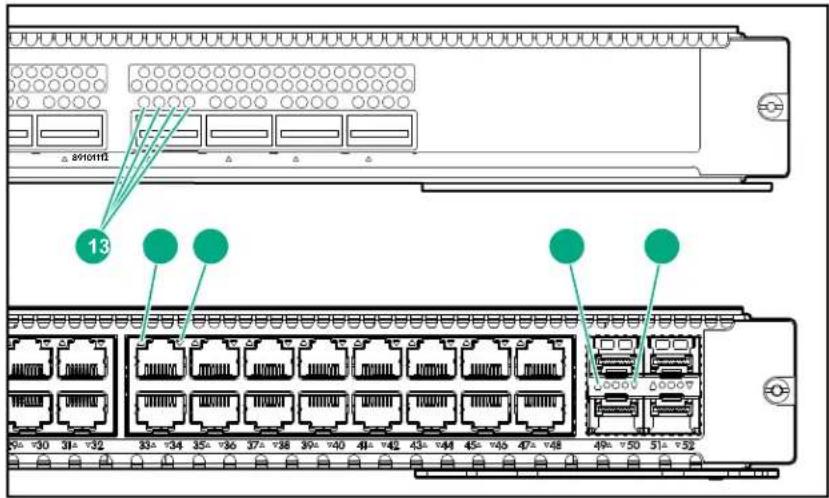
| 1 | Line module 4-channel port LEDs |
| 2 | Line module port LED for upper port |
| 3 | Line module port LED for lower port |
| 4 | Line module port LED for upper uplink port |
| 5 | Line module port LED for lower uplink port |
The LED behavior is set by the LED Mode button on the management module.
Power cords and inlet adapters

IMPORTANT:
- Use only an Aruba 6400 C16 inlet adapter with an R0X35A Aruba 6400 1800W power supply.
- Use only an Aruba 6400 C20 inlet adapter with an R0X36A Aruba 6400 3000W power supply.
Using C16 inlet adapters with the 3000W power supplies, or using C20 inlet adapters with 1800W power supplies is not supported.
Aruba includes the power cords and inlet adapters approved for use with your Aruba 6400 switch. A C16 inlet adapter is shipped with each 1800W R0X35A PSU; a C20 inlet adapter is shipped with each 3000W R0X36A PSU. Different countries or regions may require different power cords. A list of the power cords that apply to your Aruba 6400 switch power supply units is provided under 1800W PSU C15 Power cord information, and 3000W PSU C19 Power cord information.

WARNING: Remove all power cords from the switch and power supply unit before mounting or dismounting the switch.
Rear of the switch
The rear of the switch includes:
- Four AC power receptacles for receiving the inlet adapters shipped with the PSUs (C16 or C20 inlet depending on the power supplies ordered with the system)
- Fan trays
On the 6405 switch: Two fan trays with four fixed fan modules each
°On the 6410 switch: Four fan trays with four fixed fan modules each - Rear LED display
- Grounding lug
As an example, the following figure indicates the location of the slots and modules on a 6405 switch (the 6410 has two more fan trays below those shown in this figure).
Figure 13: Aruba 6405 rear panel
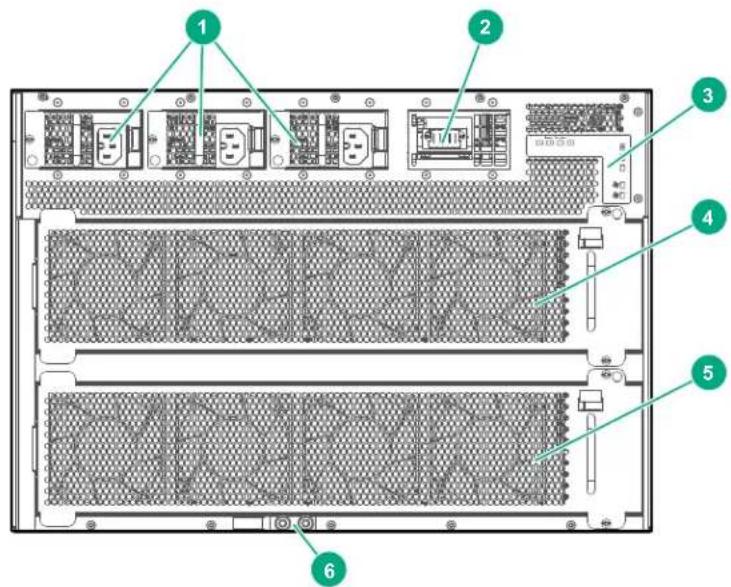
| 1 AC | power inlet accessories |
| 2 Uncovered AC power inlet accessory slot | |
| 3 Rear LED display panel | |
| 4 Fan tray 1 | |
| 5 ^1 | Fan tray 2 |
| 6 Grounding lug | |
1 Note the 6410 switch includes two more fan trays (trays 3 and 4).
Fan trays
The Aruba 6400 switch hot swappable fan trays (two on the 6405 and four on the 6410) house four fixed fans each, providing a total of eight (6405) or 16 (6410) fixed fans.
Fan tray
Figure 14: Fan tray
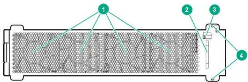
| 1 Fixed fans (4) |
| 2 Handle for removing or installing the fan tray |
| 3 Fan tray release latch |
| 4 Screws for securing the fan tray in a fan tray slot |
Fan tray status LEDs are on the active management module and on the rear LED display. See Management module (MM) slots and Rear panel LEDs for more information.

NOTE: If the active management module or ArubaOS-CX operating system detect that a fan tray has failed, all remaining fans will automatically operate at maximum speed.
Rear panel LEDs
Figure 15: Rear panel LEDs

| 1 Power supply status (1) (2) (3) (4) |
| 2 Chassis power LED |
| 3 Chassis health LED |
| 4 Chassis identification (UID) LED |
| 5 Fan tray status (two LEDs on 6405, four LEDs on 6410) |
Power cords, power inlet accessories, and power supplies
Aruba includes the power cord approved for use with your Aruba switch and power supply. Different countries/regions may require different power cords. For a list of the power cords approved for use with your Aruba 6400 switch, see the section that lists power cords under Power cord information.

CAUTION: Only Aruba-approved power cords are supported for use with Aruba devices. Lost or damaged power cords must be replaced only with Aruba-approved power cords. If your installation requires a different power cord than the one supplied with the switch and/or power supply, be sure that the cord is adequately sized for the current requirements of the switch. In addition, be sure to use a power cord displaying the mark of the safety agency that defines the regulations for power cords in your country or region. The mark is your assurance that the power cord can be used safely with the switch and power supply.

WARNING: Do not use a damaged or non-recommended power cord with your switch. Using such power cords voids the switch and power supply warranty. It can also cause serious electrical problems, including injury or death to personnel, and damage to the switch and other property. If you cannot verify that you have a power cord approved for use with your switch model, contact your authorized Aruba dealer or sales representative for assistance.

WARNING: Remove the power cord from the switch and power supply before mounting or dismounting the switch.
Power cord information
Japan power cord warning
1800W PSU C15 Power cord information

NOTE: The R0X35A (1800W) PSU, when operating at high line (200-240 VAC), provides 1800W of power. When operating at low line (110-127 VAC), the R0X35A provides 1100W of power.
Table 9: C15 power cord types for the Aruba 6400 1800W Power Supply (R0X35A)
| Country or region Part # Option | 1 | SKU Description | ||
| Argentina 8121-1481 #ARM J9 | 960A HPE 2.5m C15 to IRAM 2073 250V | Power Cord | ||
| Australia/New Zealand 8121-1 | 476 #ABG J9941A HPE 2.5m C15 to SAA/3 250V Power Cord | |||
| Brazil 8121-1265 #AC4 J9951A | HPE 2.5m C15 to BR3 10Amp 250V | Power Cord | ||
| Chile 8121-1477 #A1X J99 | 46A HPE 2.5m C15 to CEI 23-50 3-pole | 250V Power Cord | ||
| China | 8121-1484 | #AKM J9 | 949A HPE 2.5m C15 to PRC/3 250V Power Cord | |
| Continental Europe | 8121-1479 | #ABB | J9945A | HPE 2.5m C15 to CEE 7-VIIG 250V Power Cord |
| Denmark | 8121-1486 #ACE J9948A HPE 2.5m C15 to DK 2-5A 250V Power Cord | |||
Table Continued
| Country or region Part # Option | 1 | SKU Description | ||
| India 8121-1721 #ACJ JL696A | HPE 2.5m C15 to ZA | /3 250V Power | Cord | |
| Israel 8121-1478 #AKJ J9958A | HPE 2.5m C15 to IL | -3 90 Degree | 250V | Power Cord |
| Japan high line 8120-8945 #ACF | JL336A HPE 2.5m | C15 to 498 | GJ JP 3-pole | 125V Power Cord |
| Japan low line 8121-1738 #ACF | JL352A HPE 2.5m | C15 to 6/15 | AJ 200V 15 | AmpJP Non-locking Power Cord |
| South Africa | 8121-1483 | #ACQ | J9956A | HPE 2.5m C15 to ZA/3 250V Power Cord |
| South Korea | 8121-1479 | #AC6 | J9945A | HPE 2.5m C15 to CEE 7-VIIG 250V Power Cord |
| Switzerland | 8121-1480 | #ACD | J9957A | HPE 2.5m C15 to SEV 6534-2 Type 12G 250V Power Cord |
| Taiwan | 8121-1511 | #ARB | J9947A | HPE 2.5m C15 to TW15CS3 125V Power Cord |
| Thailand | 8121-1485 | #AKL J9952A HPE 2.5m C15 to NEMA 5-15P TH 250V Power Cord | ||
| UK, Malaysia | 8121-1475 | #ACC, #ARE | J9942A HPE 2.5m C15 to BS 1363/A 250V Power Cord | |
| North America | 8121-0914 | #ABA | J9953A | HPE 2.5m C15 to NEMA 5-15P Power Cord |
| 220V North America Locking | 8121-0941 | Non-Locking Hi-voltage | J9955A HPE 2.5m C15 to NEMA L6-20P 250V Locking Power Cord | |
| PDU Cable NA/JP/TW ^2 | 8121-1091 | #B2B | J9943A HPE 2.5m C15 to C14 PDU NA/JP/TW Power Cord | |
| PDU Cable Rest of World (except India) | 8121-1094 | #B2C | J9944A HPE 2.5m C15 to C14 PDU Rest of World Power Cord | |
| PDU cable, India P09373-001 | PDU for | India | JL672A HPE 2.5m C15 to C14 PDU India Power Cord | |
| 220V NA (North America) | 8120-8945 | #B2E | JL336A | HPE 2.5m C15 to NEMA 6-20P 250V Non-locking Power Cord |
1 The Option (#xxx) is specified for the country/region where the unit will be installed to have the proper power cord included with the purchase. If needed, the SKU number can be ordered separately through normal Aruba purchase channels.
2 NA (North) America; JP (Japan); TW (Taiwan).
3000W PSU C19 Power cord information

NOTE: The R0X36A (3000W) PSU, when operating at high line (200-240 VAC), provides 3000W of power. When operating at low line (110-127 VAC), the R0X36A PSU provides 1500W of power.
Table 10: C19 power cord types for the Aruba 6400 3000W Power Supply (R0X36A)
| Country or region | Part number Option SKU Description | |||
| Argentina 8121-09 | 25 #ARM JL339A | HPE 2.5m C19 to | RAM 2073 20Amp | 250V Power Cord |
| Brazil 8121-1101 # | AC4 JL343A HPE 2 | 5m C19 to BR3 | 20Amp 250V | Power Cord |
| Chile 8121-0923 #A | 1X JL338A HPE 2 | 5m C19 to CEI 23 | 50 16Amp | 250V Power Cord |
| China 8121-1551 # | AKM JL347A HPE | 2.5m C19 to PRC/3 | 16Amp | 250V Power Cord |
| Continental Europe | 8121-1554 | #ABB | JL350A HPE | 2.5m C19 to CEE 7-VIIGK 250V Power Cord |
| India 8121-1074 | #ACJ | JL341A HPE | 2.5m C19 to ZA/3 | 16Amp 250V Power Cord |
| Israel | 8121-1010 | #AKJ | JL340A | HPE 2.5m C19 to SI 32 90 Degree 250V Power Cord |
| Japan 8121-1737 # | ACF JL353A HPE 2 | 5m C19 to 6/15A | J 200V | 15Amp JP Non-locking Power Cord |
| North America | 8121-1553 | #ABA | JL349A | HPE 2.5m C19 to NEMA 5-20P 125V Power Cord |
| South Africa | 8121-1552 | #ACQ | JL348A | HPE 2.5m C19 to ZA/3 16Amp 250V CN Power Cord |
| South Korea | 8121-1554 #A | C6 JL350A HPE 2 | 5m C19 to CEE 7 | VIIGK 250V Power Cord |
| Switzerland 8121-09 | 916 #ACD | JL337 | A HPE 2.5m C19 | to SEV 6534-2 Type 12G 250V Power Cord |
| Taiwan | 8120-6362 | #ARB, Locking Hi-Voltage | JL335A HPE | 2.5m C19 to NEMA L6-20P 250V Locking Power Cord |
| Thailand | 8121-0922 | #AKL JL764 | A HPE 2.5m C19 | to LP45 16A 250V Thailand Power Cord |
| UK, Malaysia, Australia/New Zealand, Denmark | 8121-1287 | #ACC, #ARE, #ABG, #ACE | JL344A HPE | 2.5m C19 to PCE013-6 250V Power Cord |
| PDU Cable NA, JP, TW, and RoW except India | 8121-1090 | #B2B, B2C JL3 | 42A HPE 2.5m C1 | 9 to C20 250V PDU Power Cord |
| PDU cable, India | P09372-001 | PDU for India | JL673A | HPE 2.5m C19 to C20 PDU India Power Cord |
| 220V NA (North America) | 8121-1555 #B | 2E JL351A HPE 2 | 5m C19 to NEMA | 6-20P 250V 20Amp Non-locking Power Cord |
Power over Ethernet (PoE) operation
PoE is enabled by default on the following Aruba 6400 line modules:
Table 11: Aruba 6400 switch line modules
| SKU Aruba line module PoE per port1 | Standard EA Certified logo | |||
| R0X38B Aruba | 6400 48-port 1G Class 4 PoE 30W 802.3 | at (Type | 2) |  |
| R0X39B Aruba | 6400 48-port 1G Class 4 PoE & 4-SFP56 | 30W | ||
| R0X40B Aruba | 6400 48-port 1G Class 6 PoE & 4-port SFP56 | 60W 802.3 | pt (Type 3) |  |
| R0X41A Aruba | 6400 48-port SR Class 6 PoE & 4-port SFP56 | 60W | ||
^1 For standards-compatible powered devices.
For instructions on using the switch PoE features, see the Monitoring Guide for your switch.
Ethernet Alliance PoE Certified
Certified Aruba PoE power sourcing equipment (PSE) has been verified for IEEE 802.3 ^™ PoE interoperability by passing the Ethernet Alliance (Gen 1 or Gen 2) PoE Certified program test plan, minimizing interoperability issues between PoE products.
The Ethernet Alliance PoE Certification Program provides thorough testing of PoE devices for interoperability with IEEE 802.3 ^™ PoE standard devices. Certified products will be easily recognizable by the logos below, which also identify the amount of power available or required. User experience will be enhanced by minimizing confusion between standards-based PoE from proprietary powering solutions.
Gen 1 EA PoE Certified Logo Gen 2 EA PoE Certified Logo

EA Certified
TM

EA Certified 2.0 ^TM
For more information on EA PoE Certification, visit the Ethernet Alliance website.
Aruba 6400 PoE operation includes these features:
• Maximum PoE power per slot is 2880W
- Both the Aruba 6405 and Aruba 6410 switches support a maximum PoE load of more than 10,000W with four power supply units of 3,000W installed
- Interoperates with IEEE 802.3af, IEEE 802.3at, and IEEE 802.3bt compliant Powered Devices (PD)
- Compatible with non-Aruba, pre-standard IEEE 802.af PDs ^1
- Detects and supplies power to Single Signature (SS) Type 1-4 PDs
- Detects and supplies power to Dual Signature (DS) Type 3-4 PDs
- Long first class event supported on Type 3-4 PSE
- Multi-Event classification permits mutual ID of SS Class 0-8 and DS Class 1-5
• Support LLDP Data Link Layer (DLL) Type 1-2 extension 12-octet TLV and Type 3-4 extension 29-octet TLV - Default PSE assigned class delivers the maximum PSE capable power at initial power up based on PD requested class
- Always-on PoE is a feature that provides the ability for a switch to continue to provide power across user initiated reboots through software. Always-on PoE is enabled by default and no additional configuration is needed.
- Continues to deliver power during "warm" reboot of the switch
- Conducts power management based on port priority configuration
- Delivers Rapid Power Down (RPD) of PDs in the event of a PSU failure
- Delivers SNMP trap support for port-status change and threshold limit
- Provides LED indication of PoE status and fault
For more information on Aruba 6400 Switch PoE operation, see Power Over Ethernet (PoE) Planning and Implementation Guide for ArubaOS-CX Switches.
Switch software features
For information on the Aruba 6400 Switch Series software features, visit https://asp.arubanetworks.com/downloads
Unpacking the switch components
Prerequisites
Identify the components received with your Aruba 6400 Switch Series chassis.

NOTE: Some components may ship separately from the pallet on which you received your 6400 Series chassis.
Procedure
- Open the top of the carton.
a. Remove the documentation folder.
b. Read the warning information included in the Unpacking Information booklet.

WARNING: The switch is heavy. To avoid possible injury, see the Unpacking Information booklet before moving the switch.
-
Remove all of the accessories.
-
Lift the top carton off of the chassis.
-
Remove any remaining packing material covering the switch.
-
Pull the poly covering away to expose the top, front, sides, and rear of the chassis.
-
Verify that the components you ordered are included in the shipment(s) you received. Components may include the following items shipped either on a pallet or in one or more separate packages.
Figure 16: Hardware components
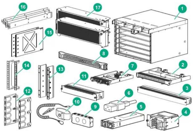
| Item Description Item Description | ||||
| 1 Aruba 6400 Switch Series chassis 10 ESD wrist strap | ||||
| 2 Line module 11 Management module slot cover | brackets | |||
| 3 Line module slot cover 12 Cable manager bulkheads | ||||
| 4 AC inlet accessory. (One shipped with each PSU.) | 13 Rear post rack brackets | |||
| 5 Power supply unit (PSU) 14 Front rack mounting | ||||
| 6 Power cord (One shipped with each PSU) | 15 Rear adapter plate | |||
| 7 Management module 16 Rail spacers | ||||
| 8 Front panel bezel 17 Fan trays | ||||
| 9 Power supply slot cover | ||||
Power cord information

CAUTION:
- Use only Aruba-approved and recommended power cords. For proper power cord selection, see Power cords, power inlet accessories, and power supplies.
- If your installation requires a different power cord than the one supplied with the chassis or power supply unit, be sure the cord is adequately sized for the chassis or PSU current requirements. In addition, be sure to use a power cord displaying the mark of the safety agency that defines the regulations for power cords in your country. The mark is your assurance that the power cord can be used safely with the chassis and PSU.
Attaching an ESD wrist strap
Aruba provides an ESD wrist strap with the switch. To minimize ESD damage to electronic components, wear the ESD wrist strap and make sure it is reliably grounded when handling, installing, or removing switch components.
To use an ESD wrist strap:
Prerequisites
• See Preventing electrostatic discharge damage.
- Locate the ESD wrist strap shipped with your Aruba 6400 switch.
Procedure
- Put on the wrist strap.
- Tighten the wrist strap to make sure it makes good skin contact. Make sure the resistance reading between your body and the ground is between 1 and 10 megohms.
- Attach the wrist strap securely to the front or rear of the chassis.
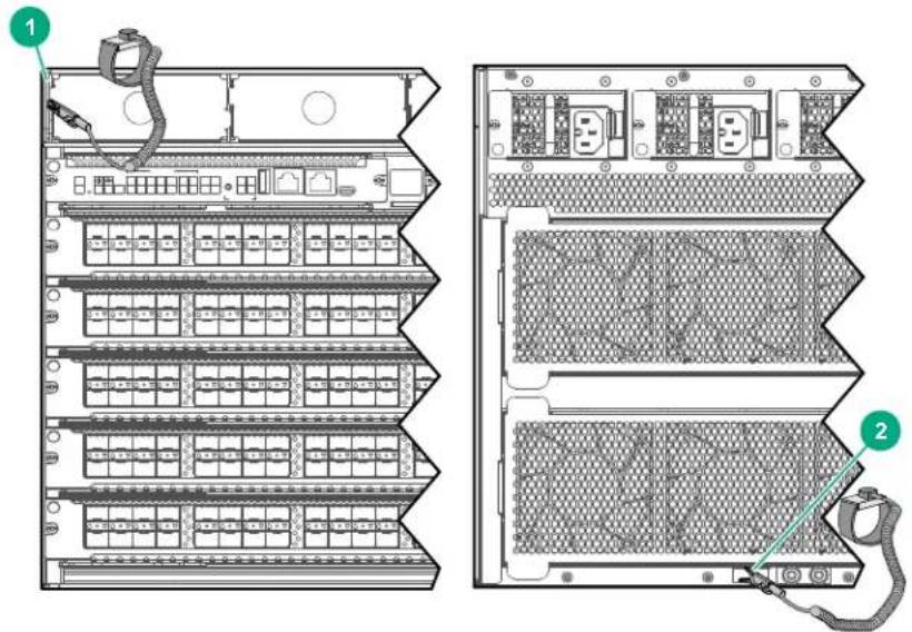
| 1 ESD wrist strap connection on a chassis edge near the power supply slot on the switch front panel |
| 2 ESD wrist strap connection on the grounding lug on the rear panel |
Removing installed components from the chassis
Skip this section and see Using a mechanical lift to move the chassis if you are using a mechanical lift for all chassis movement and mounting steps.
After removing the power supplies, line modules, and fan trays as described completing the preceding actions, the switch weight is sufficiently reduced for carrying by four people.

IMPORTANT: Fully populated Aruba 6400 switches weigh up to:
• 6405: 61 kg (133 lbs)
• 6410: 100 kg (219 lbs)
If you are manually moving the switch, or if the configured weight exceeds the lift capacity, then use the steps in this section to reduce the weight of the switch for safe manual moves.

CAUTION: To prevent electrostatic discharge (ESD) damage to switch components, follow these guidelines:
- Prepare an ESD-safe area to receive the removed components.
• Always wear an ESD wrist strap and make sure it is reliably grounded when installing or removing modules or other components. For information on how to use an ESD wrist strap, see Grounding.
- Hold modules by their edges. Do not touch any electronic components or printed circuit.
- Store uninstalled modules in antistatic bags for future use.
The following sections list the steps for removing chassis components.
Remove installed power supply units
Procedure

CAUTION: Handle your Aruba 6400 switch power supplies with care. Rough or careless handling can damage the power supplies and result in unplanned down time.
-
Remove all power cords from the switch.
-
Remove the bezel, if installed.
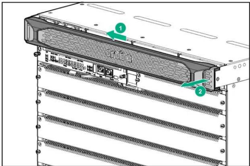
- Remove all installed power supply units.
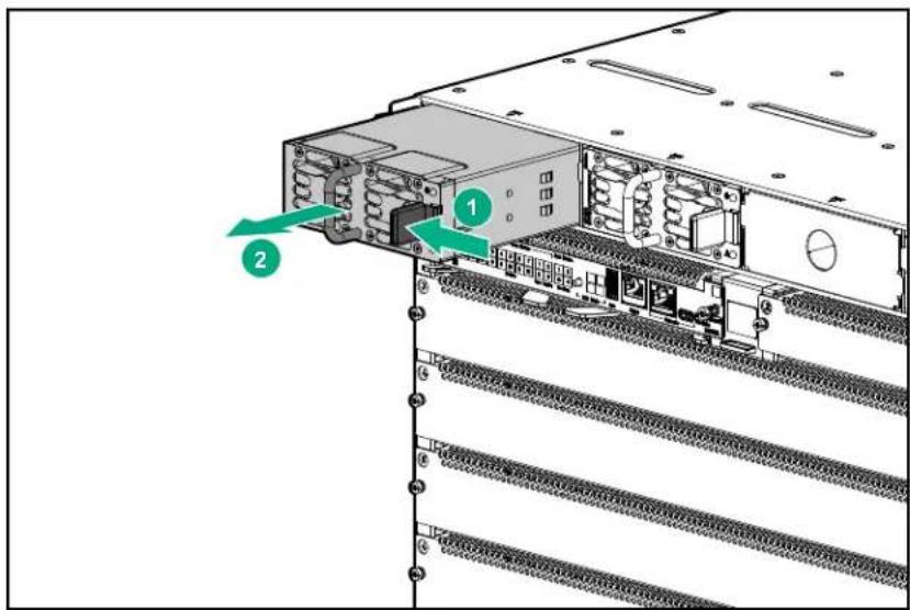
- When one or more power supply units are installed, place a power supply slot cover on all empty power supply slots.
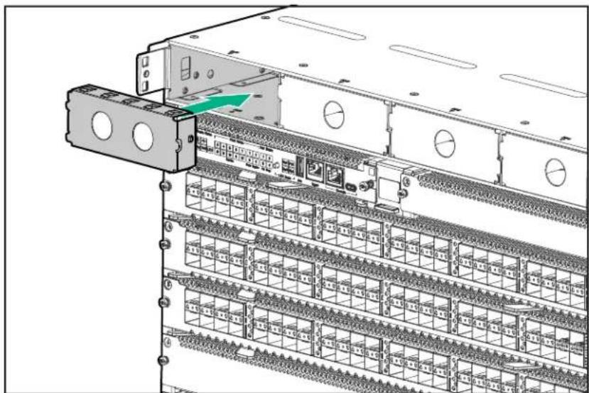
natural_image
Diagram of a server rack with multiple drive bays and a green arrow indicating a specific component (no text or symbols present)Remove any installed line modules
Procedure

CAUTION: Handle your Aruba 6400 switch line modules with care. Rough or careless handling can damage the modules and result in unplanned down time.
- Remove any installed line modules from slots 3 through 7 on the Aruba 6405 switch or slots 3 through 12 on the Aruba 6410 switch.
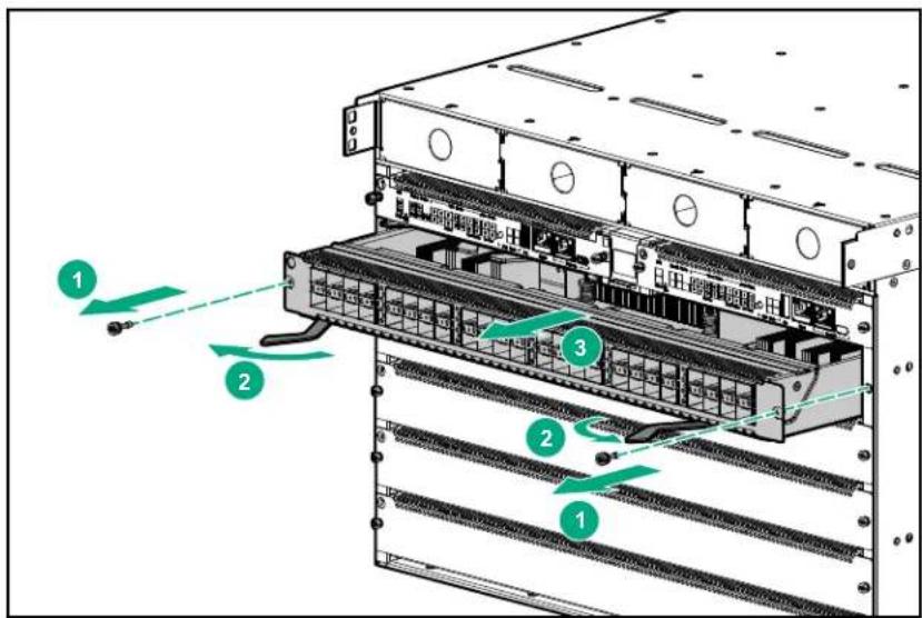
-
Place removed line modules in anti-static bags.
-
Install line module slot covers on all empty line module slots.

NOTE: Leave any installed Management modules in the chassis. Removal of power supplies, line modules, and fan trays is sufficient to reduce the chassis weight for four-person lifting and moving.
Remove the fan trays

IMPORTANT: Before manually moving an Aruba 6400 switch:
- Remove both fan trays from an Aruba 6405 switch.
- Remove all four fan trays from an Aruba 6410 switch.
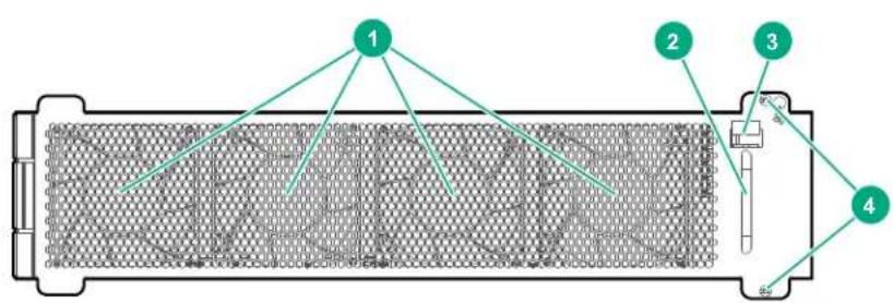
| 1 Permanently fixed fans |
| 2 Handle for inserting or removing fan tray |
| 3 Latch |
| 4 Screws for securing fan tray in chassis |
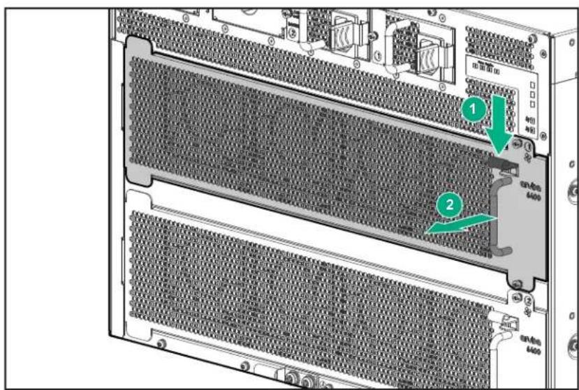
Procedure

CAUTION: Handle your Aruba 6400 switch fan trays with care. Rough or careless handling can damage these components and result in unplanned down time.
-
Select a fan tray to remove.
-
Loosen the retaining screws securing the fan tray to the chassis.
-
Depress the fan tray latch to release the right end of fan tray from the chassis.
-
Using the fan tray handle, swing the right end of the fan tray out of the slot and pull the fan tray away from the slot.
-
Repeat steps 2 through 4 to remove the other fan trays.

NOTE: On an operating switch, remove only one fan tray at a time. Removing more than one fan tray at a time compromises system cooling, risks damage to the hardware, and can cause the switch to shut down abruptly.
After removing the power supplies, line modules, and fan trays as described completing the preceding actions, the switch weight is sufficiently reduced for carrying by four people using the provided lift handles.
Move the chassis to the mounting location
Manually moving the chassis
Prerequisites

NOTE:

WARNING: Mount devices installed in a rack or cabinet as low as possible. Mount the heaviest devices at the bottom of the rack and lighter devices higher up.
- If you are using a mechanical lift, skip this step and see Using a mechanical lift to move the chassis.
- All fan trays, all line modules, and all power supply units are removed from the chassis.
- Ensure that the equipment rack or other switch mounting site is prepared to receive the chassis. See Site preparation
Procedure
- Remove the foam cushions from the right and left side of the chassis. Ensure that the breakaway foam pieces at the chassis base on each side of the chassis are removed, exposing the bottom edge of each side of the chassis.
- Pull away the poly bag covering the chassis to expose the bottom edge of the chassis on both sides.
- Using four people, carefully lift the chassis and move it to the mounting location.
Using a mechanical lift to move the chassis
Prerequisites

WARNING:
A fully populated Aruba 6405 switch weighs up to 61 kg (133 lbs); a fully populated Aruba 6410 switch weighs up to 100 kg (219 lbs). Ensure that the combined weight of the chassis with all components installed does not exceed the maximum load capacity of your mechanical lift.
If you are not using a mechanical lift, then skip this section and see Manually moving the chassis.
If you are using a mechanical lift to move and mount the chassis, then it is not necessary to remove the switch components unless the combined weight of the chassis and installed components exceeds the maximum load capacity of the lift. If the lift capacity is less than the weight of your switch, then see Aruba 6400 product weights for details on determining the populated weight of your switch. Then determine which components to remove to lower the chassis weight to less than the maximum load capacity of your lift.
Procedure
- Expose the bottom edge of the chassis front panel by:
a. Removing the front foam breakaway cushions.
b. Releasing the tabs on the cardboard tray.
c. Pulling the tray sides down.
d. Tucking the poly bag out of the way.
- Position the mechanical lift on the same level as the front, bottom edge of the chassis, and touching the chassis.
- Lock the lift wheels.
- Slide the chassis as far forward as possible onto the lift.
- Raise the lift enough to allow it to clear the shipping pallet.
- Unlock the lift wheels and move the chassis to its mounting location.

CAUTION: Raise the chassis only as high as needed to clear any obstacles in the path to the mounting location.

WARNING: If you are manually mounting the switch instead of using a mechanical lift, then before proceeding in this chapter, reduce chassis weight by removing any installed switch components, as described under Removing installed components from the chassis

NOTE: Unless otherwise noted, instructions in this chapter apply to both the Aruba 6405 Switch and the Aruba 6410 Switch.
(Optional) Installing the chassis in a non-rack mounted position
Skip this procedure if you plan to mount the switch in an equipment rack. (See Mounting the chassis in a rack.)
The following conditions must be met when performing a rack-free installation:
- A fully-populated Aruba 6405 Switch can weigh up to 61kg (133 lbs) and a fully populated Aruba 6410 Switch can weigh up to 100kg (219 lbs). The structure and floor supporting the switch must be able to withstand this weight.
- The switch should be supported by a sturdy, flat surface.

NOTE: The chassis is not equipped with rubber feet. Take care to avoid marking or scratching the mounting surface.

WARNING: To reduce the risk of personal injury or damage to equipment in a rack-free environment:
- Never stack the Aruba 6400 chassis on top of another chassis or other equipment.
- Never place equipment on top of the Aruba 6400 chassis.
- Never place an Aruba 6400 chassis on a surface that cannot support the weight of the fully populated chassis. (up to 61 kg (133 lbs) for a 6405 model and up to 100 kg (219 lbs) for a 6410 model.)
Manually positioning the chassis on a non-rack mount surface
Skip this step if you plan to use a mechanical lift to move the chassis.
Procedure
- Ensure that site preparation for the mounting site has been completed. See Site preparation.
- Move the switch to the mounting site as described under Move the chassis to the mounting location.
- Position the switch with the rear of the chassis resting on the mounting surface.
-
Slide the chassis onto the mounting surface.
-
Carefully slide the chassis into the desired position on the mounting surface.
- Go to Grounding the chassis.
Using a mechanical lift to position the chassis on a non rack mount surface
Procedure
- Move the switch to the mounting site as described under Move the chassis to the mounting location.
- Position the switch with the rear of the chassis over the mounting surface.
- Lock the lift wheels.
- Lower the chassis until its rear edge rests on the mounting surface.
- Carefully slide the chassis onto the mounting surface and into the desired position.
- Unlock the lift wheels.
- Remove the mechanical lift and go to Grounding the chassis.
Mounting the chassis in a rack

CAUTION: Mount devices installed in a rack or cabinet as low as possible. Install the heaviest device at the bottom and install progressively lighter devices above.

CAUTION: Cooling air enters through the chassis front panel and exhausts through the chassis rear panel. Ensure that there is adequate airflow space of 30 cm (11.8 inches) between the front and rear panels of the chassis and other equipment or obstructions. For more on space and measurements, see Product dimensions.
Shipping a rack-mounted Aruba 6400 switch chassis
Aruba supports shipping of rack-mounted Aruba 6400 switches where the rack or cabinet is:
- A Hewlett Packard Enterprise four-post rack product compatible with the R0X37A 4 Post Rack Mount Kit.
• Certified for integrated shipping. - Mounted to a shock pallet.
- Mounted with the R0X37A 4 Post Rack Mount Kit.

NOTE: For information on Hewlett Packard Enterprise rack products, visit https://www.hpe.com/us/en/product-catalog/servers/server-racks.hits-12.html.
Aruba does not support shipping rack-mounted Aruba 6400 switches in:
- Two-post racks
- Racks not certified for integrated shipping
- Racks not mounted on a shock pallet
• Racks not offered by Hewlett Packard Enterprise
• Hewlett Packard Standard Series racks

CAUTION: Shipping an Aruba 6400 switch chassis in a two-post rack is not supported and may result in damage to the switch or components. The Aruba warranty does not apply to products damaged or rendered defective as a result of using non supported shipping methods.
- Remove all installed management modules, line modules, power supply units, and fan trays to lighten chassis for rack installation. These items can be reinstalled after the chassis is secure.
- Install slot covers over all management module and line module slots.
-
Securely mount the switch in a compatible four-post rack or cabinet. Use the R0X37A 4-post Rack Rail Kit as described in this guide under Preparing the chassis for an optional four-post rack mount. Include secure installation of the following mounting support hardware packed in the rack rail kit:
-
Rear support plates
- Rear mounting brackets
For detailed mounting information, see Preparing the chassis for an optional four-post rack mount.

CAUTION: Switch packaging is not designed to accommodate transceivers installed in line modules. If you plan to re-ship the switch in its original packaging, remove any transceivers installed in line modules before preparing the switch for shipment.
Two-post rack mounting
Preparing the chassis for a two-post rack mounting
Prerequisites
- A two-post equipment rack assembled and properly secured.
- Verification that the rack is certified to support the weight of all equipment you plan to mount on it. (For Aruba 6400 switch and component weight information, see Aruba 6400 product weights.)
- The front rack mounting brackets, related screws, and screwdrivers.

IMPORTANT: The Aruba 6410 switch uses two front rack mounting brackets on each side.
- Two-post rack mount option selected.
NOTE: If you plan to install the (included) cable manager on the switch, you must install the rack mounting brackets in the front rack mount position, flanges flush with the front of the switch.
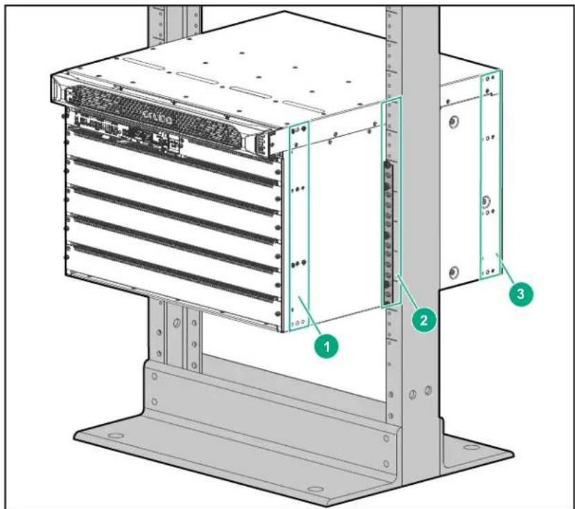
Figure 17: Two-post rack mount options
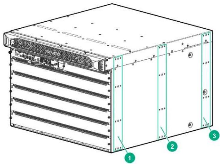
| 1 Mounting | position "1". | |
 | NOTE: If you plan to install the cable manager on the switch, you must use mounting position "1" to mount the switch in the rack. | |
| 2 Mounting | position "2". | |
| 3 Mounting | position "3". | |
Procedure
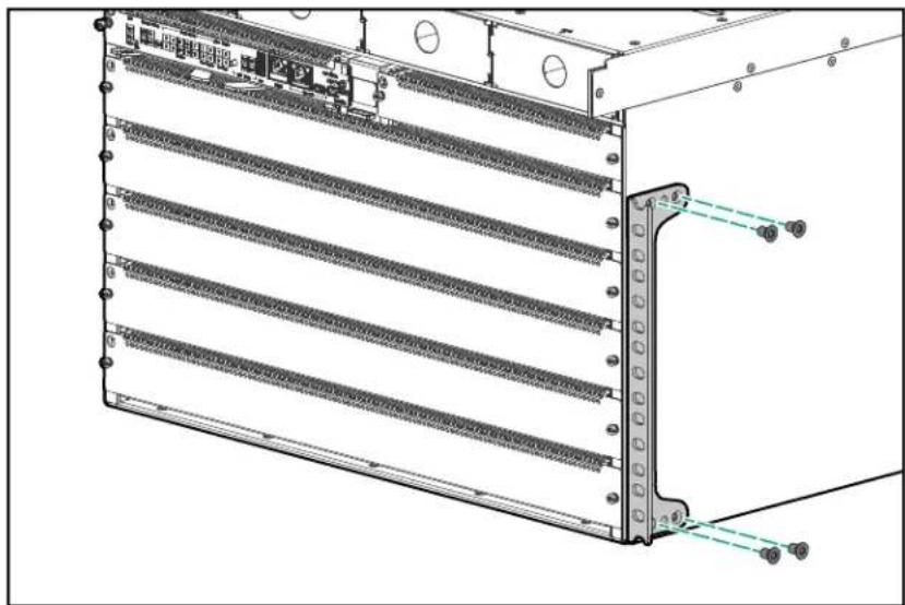
Attach the rack mounting brackets to the chassis in the selected mounting position. For a flush mount with the front of the switch, mount the rack mounting brackets with the flange toward the front of the switch. If
you are mounting an Aruba 6410 switch, use two rack mounting brackets mounted one above the other, on each side.
Figure 18: Rack mounting bracket installation using the front (number 1) mounting position on the Aruba 6405 Switch
natural_image
Technical line drawing of a server rack with multiple parallel racks and mounting holes (no text or symbols)Figure 19: Rack mounting bracket installation using the front (number 1) mounting position on the Aruba 6410 Switch
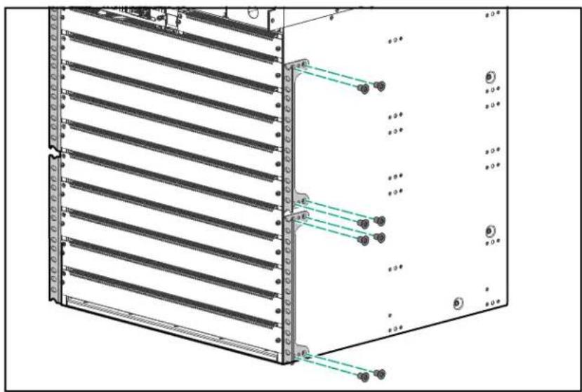
Figure 20: Two-post rack mount using the middle (number 2) mounting position
Manually mounting the chassis in a two-post rack

WARNING: This procedure is for two or more persons manually mounting an Aruba 6405 five-slot chassis weighing less than 45 kg (100 lbs), or four persons manually mounting an Aruba 6410 ten-slot chassis weighing less than 90 kg (200 lbs) in a two-post rack. For weights exceeding these limits, reduce the weight of the chassis or use a mechanical lift. See Using a mechanical lift to mount the chassis in a two-post rack for more information on using a mechanical lift. See also Aruba 6400 product weights.
Prerequisites
- The front rack mounting brackets included with the switch are installed on the chassis.
- The screwdriver and rack mounting screws are available in easy reach.
Procedure
- On both rack posts, partially install a rack mounting screw at the level you want the bottom of the chassis to rest. Leave a gap between the screw heads and the surface of the posts sufficient to allow the mounting bracket to rest on each post.
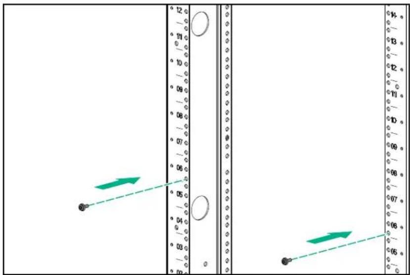
- With four people lifting, raise the switch, position it between the rack posts so that the lower ends of the rack mounting brackets rest on the screws you installed in step 1.
- Hold the switch so that the rack mounting brackets firmly contact the rack posts.
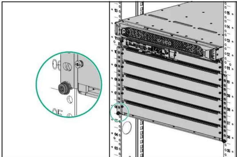
- Use the screws provided in the accessory kit to secure the chassis in the rack.

IMPORTANT:
- For the Aruba 6405 Switch, use a minimum of four screws in each of the two rack mounting brackets.
- For the Aruba 6410 Switch, use a minimum of four screws in each of the four rack mounting brackets.

WARNING: Before attempting to install components, configure the switch, or use the switch, be sure to secure it to the rack using the screws and rack mounting brackets provided. Failure to secure the chassis and supporting hardware could result in unexpected shifting or movement of the switch and risk of personal injury or product damage.
5. Go to Grounding the chassis
Using a mechanical lift to mount the chassis in a two-post rack

WARNING: A fully populated Aruba 6405 chassis weighs up to 61 kg (133 lbs). A fully populated Aruba 6410 chassis weighs up to 100 kg (219 lbs) Ensure that the combined weight of the chassis with all components installed does not exceed the maximum load capacity of your mechanical lift. For component weights, see Aruba 6400 product weights
Prerequisites
If you are not using a mechanical lift, then skip this section and see Manually mounting the chassis in a two-post rack.
The front rack mounting brackets included with the switch are installed on the chassis.
Procedure
- On both rack posts, partially install a rack mounting screw at the level you want the bottom of the chassis to rest. Leave a gap between the screw heads and the surface of the posts sufficient to allow the mounting bracket to rest on each post.
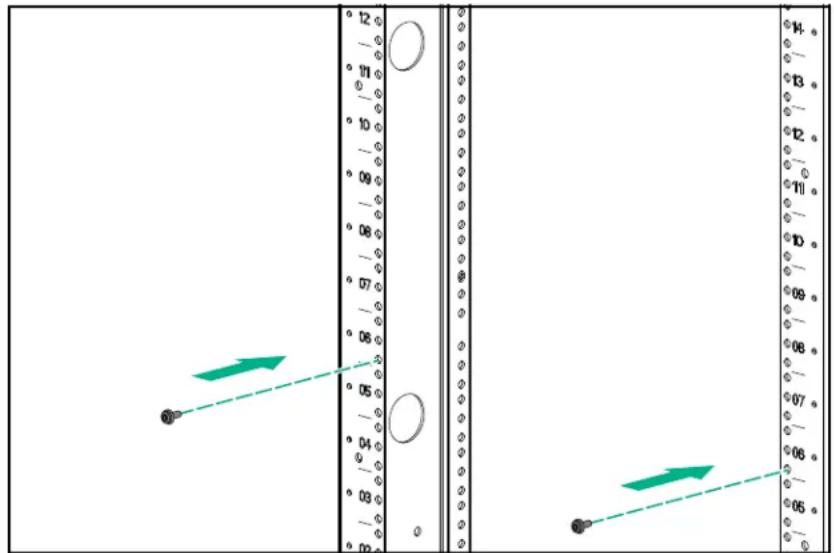
- Raise the switch and position it between the rack posts so that the lower ends of the rack mounting brackets line up to be lowered on to the screws you installed in step 1.
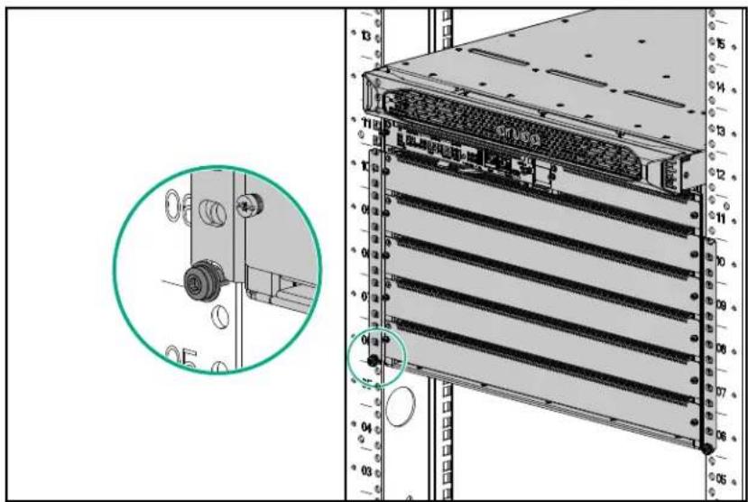
-
Lock the lift wheels.
-
Gently lower the switch so that the lower ends of the rack mounting brackets rest on the screws you installed in step 1.
-
Use the screws provided in the accessory kit to secure the chassis to the rack.

WARNING: Before attempting to configure or use the switch, be sure to secure it to the rack using the screws and rack mounting brackets provided. Failure to secure the chassis and supporting hardware could result in unexpected shifting or movement of the switch and risk of personal injury or product damage.
- Go to Grounding the chassis.
Four-post rack mounting

WARNING: Mount devices installed in a rack or cabinet as low as possible. Mount the heaviest devices at the bottom of the rack and lighter devices higher up.
Preparing the chassis for an optional four-post rack mount
To order the optional R0X37A Aruba four-post Rack Kit, contact your authorized Aruba product representative. For the front posts, you will use the same rack mounting brackets that you received with your switch. For the rear posts, you will use the contents of the four-post kit.
Installing the optional R0X37A Aruba 6400 4-post Rack Mount Kit
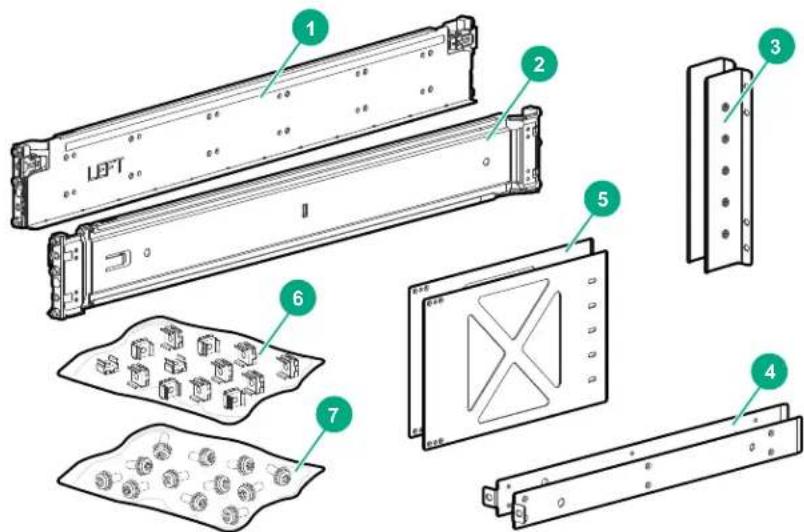
| 1 Adjustable slide rail (left side) Attaches to left side rack front and rear posts | |
| 2 Adjustable slide rail (right side) Attaches to right side rack front and rear posts | |
| 3 Rear post rack brackets Attach to rear adapter plates and to rear rack posts | |
| 4 Chassis rail spacers Attach to bottom (left-side and right-side) of chassis and front rack posts | |
| 5 Rear adapter plates Attach to chassis (left-side and right-side) in rear mounting position 3 and to rear post rack brackets | |
| 6 Cage nuts | |
| 7 Flathead and 10-32 screws | |
Prerequisites
- Ensure that the four-post rack or cabinet you plan to use is rated to support the weight of all devices you plan to install in the rack or cabinet. For information on Hewlett-Packard Enterprise racks, visit https://www.hpe.com/us/en/product-catalog/servers/server-racks.hits-12.html.
- Plan for the chassis space requirements before installing the rack mount kit. For switch dimensions, see Product dimensions.
• A four-post equipment rack or cabinet meeting the following specifications:
-19-inch rack
*Depending on which Aruba 6400 switch you are mounting, space available for a 7-Rack Unit (7U) Aruba 6405 Switch or a 13-Rack Unit (13U) Aruba 6410 Switch.
- A front and rear air flow clearance of at least 30 cm (11.8 inches). (Air flow direction is front-to-rear.)

NOTE: The four-post slide rails support only square hole and round hole rack configurations. They do not support threaded hole rack configurations.
The equipment rack shown in this publication is for illustration purposes only, and may not match the equipment rack you are using.
Installing rack rails
Procedure
- Select the desired rail position in the rack and install the adjustable rails by aligning the pins and engaging the clips front and back. The rails require 2U of rack height. The rail pins fit in the bottom and top rack holes in the lower 1U, and in the top rack hole in the upper 1U.
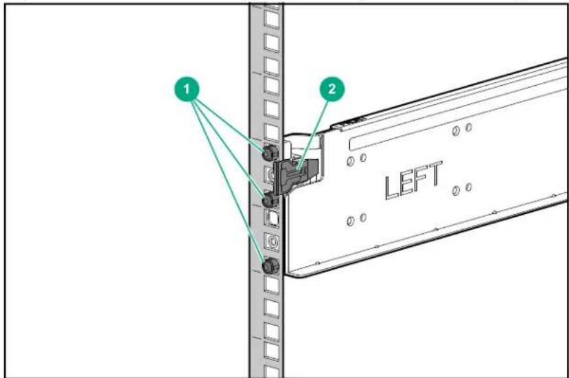
| 1 Rail pins |
| 2 Rail clip |

WARNING: Mount devices installed in a rack or cabinet as low as possible. Mount the heaviest devices at the bottom of the rack and lighter devices higher up.
- Secure both rails to the front and back posts with the included 10-32 screws, with two screws at the rear of each rail and one screw at the front of each rail in the top threaded hole.
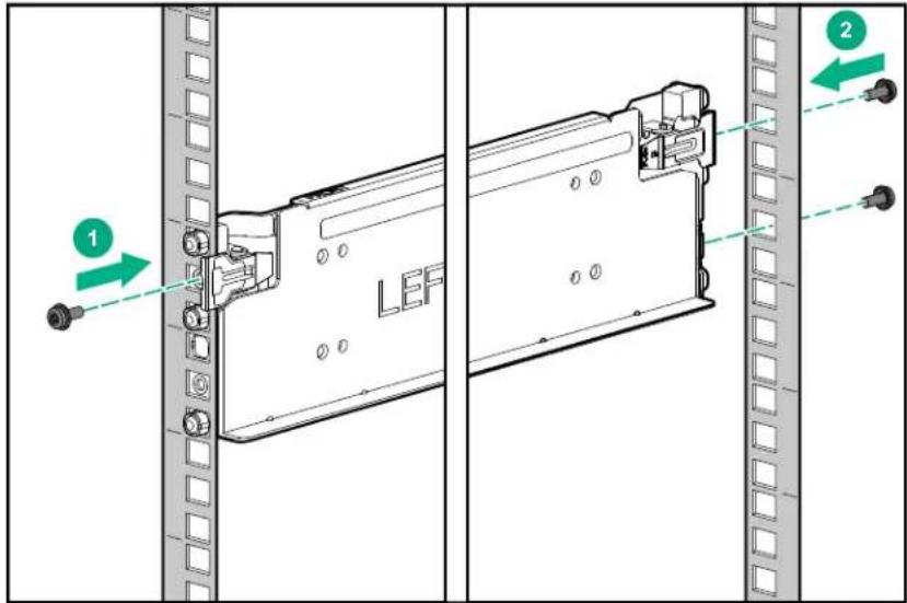
| 1 Rail secured to front post |
| 2 Rail secured to rear post |
- For mounting the Aruba 6405 Switch, install four cage nuts into the appropriate positions on each of the front posts. If you are mounting the Aruba 6410 Switch, install eight cage nuts on each front post. (That is, four cage nuts for each of the two rack mounting brackets supporting each side of the switch).
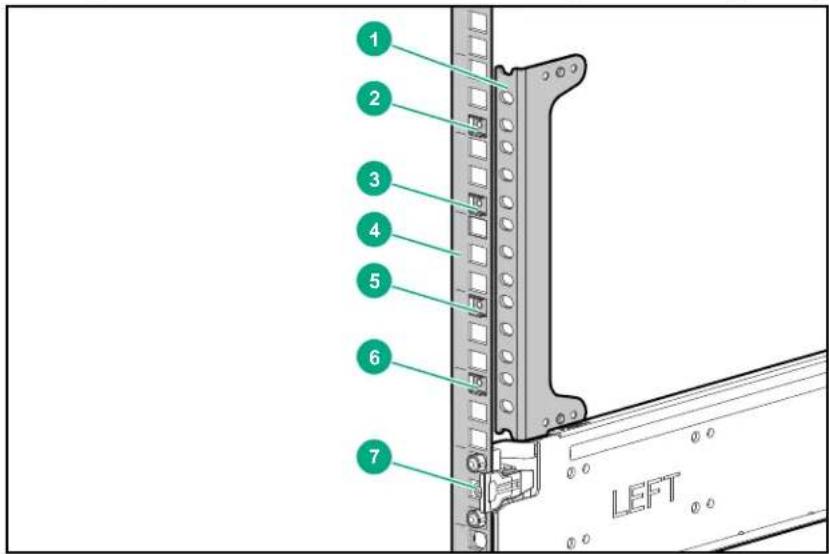
| 1 Unattached rack mounting bracket used as a guide for cage nut placement. (See step 3a, below.) | |
| 2 Cage nut at bottom of seventh 1U. | |
| 3 Cage nut at bottom of sixth 1U. | |
| 4 No cage nuts in fifth 1U. | |
| 5 Cage nut at top of fourth 1U. | |
| 6 Cage nut at top of third 1U. | |
| 7 Installed rail; uses 2U. |
a. Use an unattached rack mounting bracket to help determine the proper rack post positions for the cage nuts.
b. Insert a cage nut into the top hole in both of the 1U sections immediately above the mounted rail on both of the front posts of the rack. (See callouts 6 and 5.)
c. Skip the third 1U above the rails. (See callout 4.)
d. Insert a cage nut into the bottom hole in both of the next two 1U sections. (See callouts 3 and 2.)
Installing rail spacers and front rack mounting brackets for the four-post rack mounting
Prerequisites

NOTE: When mounting the switch in a four-post rack, the front rack mounting brackets must be attached in mounting position 1, with the flange positioned flush with the front panel of the switch.
Procedure
- Using the screws provided with the R0X37A four-post rack mounting kit, Attach a rail spacer to the bottom edge of each side of the chassis, as shown.
Figure 21: Attaching a rail spacer to each side of the chassis
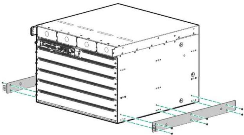
natural_image
Technical line drawing of a multi-tiered server or rack unit with mounting flanges and control panel (no text or symbols)- Use the included flat-head screws to attach the rack mounting brackets to the chassis in mounting position 1, with the flanges flush with the front panel of the switch. Use the mounting screw option that allows the bottom of the rack mounting brackets to clear the previously installed rail spacers on the lower sides of the switch. If you are mounting an Aruba 6410 switch, use two rack mounting brackets, mounted one above the other, on each side.
Figure 22: Rack mounting brackets in mounting position 1 on the Aruba 6405 Switch
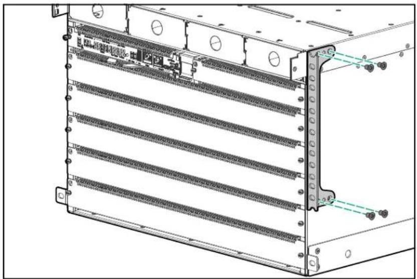
natural_image
Technical line drawing of a server rack with multiple parallel racks and mounting holes (no text or symbols)Figure 23: Rack mounting brackets in mounting position 1 on the Aruba 6410 Switch
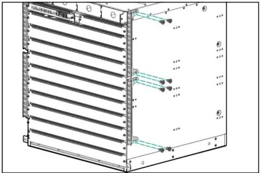
natural_image
Technical diagram of a server rack with ventilation ducts and mounting points (no text or labels)Installing rear support hardware on the chassis and four-post rack
Prerequisites
- Rack rails installed. (See Installing rack rails).
- Rail spacers and front rack earls installed. (See Installing rail spacers and front rack mounting brackets for the four-post rack mounting.)
Procedure
- Use the included flat-head screws to attach a rear adapter plate to each side of the switch.
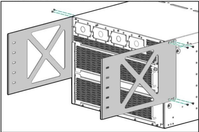
natural_image
Technical diagram of a server rack with multiple panels and mounting holes (no text or symbols)-
Install four cage nuts on each rear post to use for securing a rear bracket to each rear post. Select the cage nut positions to align with the level of the rear adapter plates installed in step 1.
-
Use the provided screws to attach a rear bracket to the rear post on each side of the rack.
Manually mounting the chassis in the four-post rack

WARNING: This procedure is for four persons manually mounting an Aruba 6410 ten-slot chassis weighing less than 90 kg (200 lbs) in a two-post rack. For weights exceeding these limits, reduce the weight of the chassis or use a mechanical lift. See Using a mechanical lift to mount the chassis in a two-post rack for more information on using a mechanical lift. See also Aruba 6400 product weights.
Prerequisites
- The four-post rack mount hardware kit is installed on your four-post rack.
- Rack mounting brackets are mounted on the front of the switch. (See Installing rail spacers and front rack mounting brackets for the four-post rack mounting.)
Procedure
-
With four people lifting, raise the switch to the level of the rack rails. (See the above Warning.)
-
Slide the switch onto the rails until the rails support the rear of the chassis.
-
Continue sliding the chassis onto the rack until the rails fully support the chassis weight.
-
Slide the chassis into the rack until the rack mounting brackets contact the front rack posts.
-
Use the screws provided in the accessory kit to secure the rack mounting brackets to the rack.

WARNING: Before attempting to configure or use the switch, be sure to secure it to the rack using the screws and rack mounting hardware provided. Failure to secure the chassis and supporting hardware could result in unexpected shifting or movement of the switch and risk of personal injury or product damage.
- On each side of the rack, attach a rear bracket.
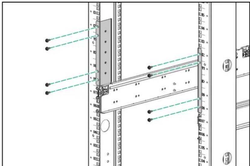
-
Using four people, slide the chassis onto the rack rails until the rack mounting brackets contact the front rack posts. Use the screws provided to secure the rack mounting brackets to the front posts.
-
Secure the rear adapter plates you installed earlier to the rear post rack brackets with the included 10-32 screws.
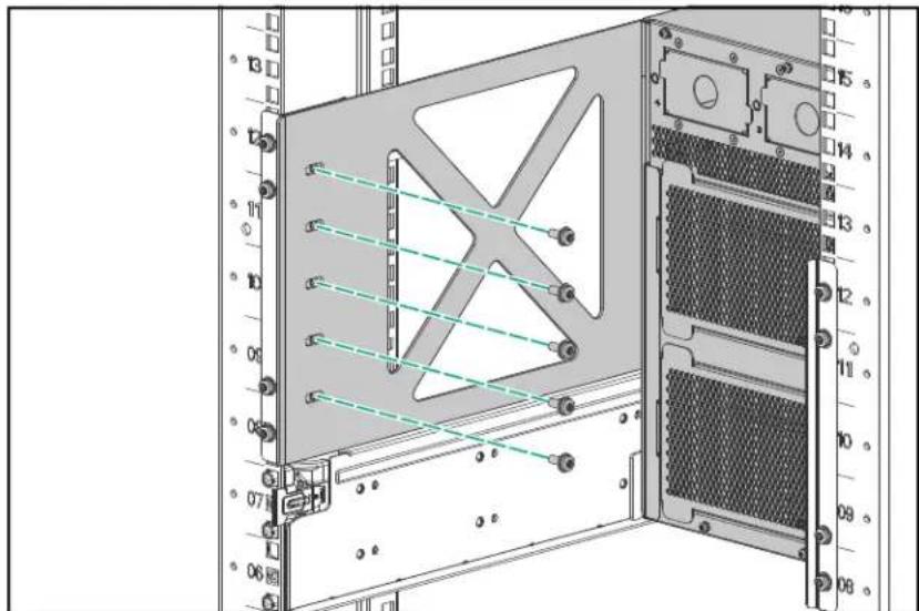

NOTE: Do not tighten the screws holding the rear bracket to the rear adapter plate until the switch chassis is installed and all parts are attached.
-
Firmly tighten the screws holding the rear brackets to the rear adapter plate.
-
Secure the front of the rack to the rack by inserting and tightening four screws in each rack mounting bracket and one screw in each spacer (10 total screws for a 6405 switch and 18 total screws for a 6410 switch).
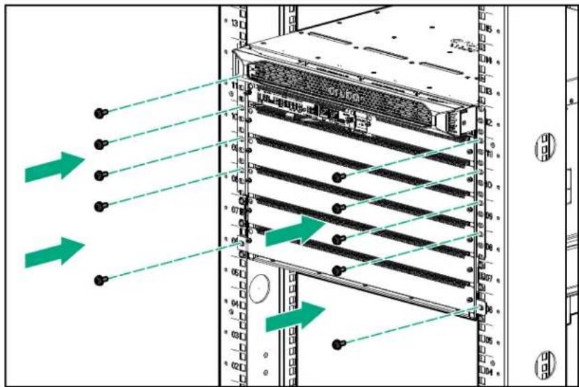
- Go to Grounding the chassis.
Using a mechanical lift to mount the chassis in a four-post rack
Prerequisites
• The R0X37A Aruba 6400 4-post Rack Mount Kit is installed on your four-post rack or cabinet.
- Rack mounting brackets are mounted on the chassis. (See Installing rail spacers and front rack mounting brackets for the four-post rack mounting.)
- The support hardware included in the four-post rack mount hardware kit is installed on the chassis and on the rear posts of the rack. (See Installing the optional R0X37A Aruba 6400 4-post Rack Mount Kit

WARNING: A fully populated Aruba 6405 chassis weighs up to 61 kg (133 lbs), and a fully populated Aruba 6410 chassis weighs up to 100 kg (219 lbs). Ensure that the combined weight of the chassis with all components installed does not exceed the maximum load capacity of your mechanical lift.
Procedure
- Raise the chassis to the level of the installed rack rails.
- Move the lift toward the rack until the lift platform is less than 2.5 cm (1 inch) from the rack mount shelf.
- Lock the lift wheels.
- Slide the chassis onto the rack mount shelf until the rack mounting brackets contact the front rack posts. Use the screws provided to secure the rack mounting brackets to the front posts.
- Secure the rear adapter plates you installed earlier to the rear post rack brackets with the included 10-32 screws.
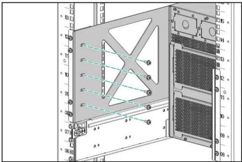
natural_image
Technical diagram of a server rack with labeled components and wiring connections (no readable text or symbols)
NOTE: Do not tighten the screws holding the rear bracket to the rear adapter plate until the switch chassis is installed and all parts are attached.
6. Go to Grounding the chassis.
Grounding the chassis

CAUTION: To protect the switch from hazards such as lightning shocks, interferences, and ESD discharges, reliably ground it. The switch is grounded through the safety wire in the power cords. If there is any doubt about the reliability of the grounding through the power mains, Aruba recommends an independent grounding connection for the chassis. Note the location of the grounding lug.
Figure 24: Grounding the chassis
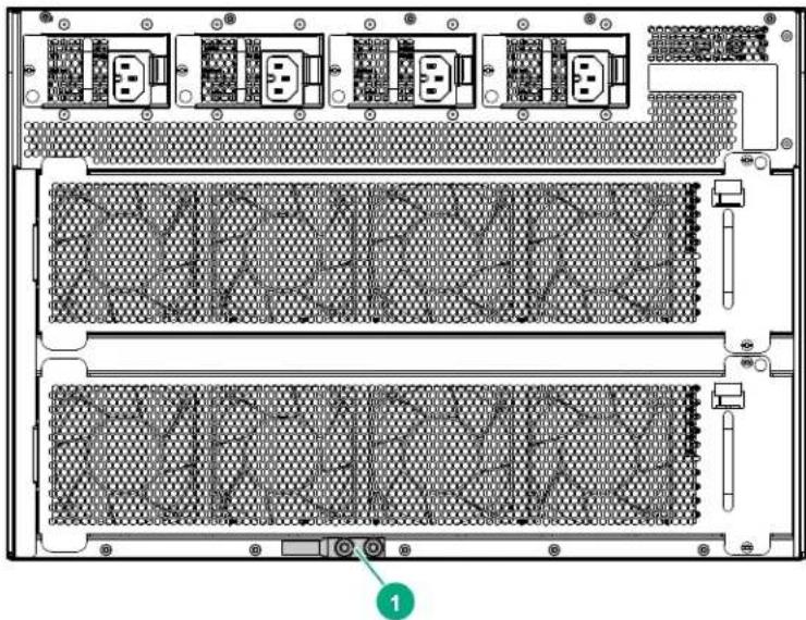
natural_image
Back view diagram of a server rack with multiple drive bays and ventilation slots (no text or labels)1 Grounding lug
Make sure the resistance between the chassis and the ground is less than 1 ohm.
Prerequisites
Use a 6 AWG stranded grounding cable.
Procedure
- Remove the grounding lug and two screws from the rear of the switch.
- Crimp the grounding lug to a properly grounded 6 AWG stranded grounding cable.
- Securely reattach the grounding lug to the switch with the two screws.
Protect the switch and components from damage caused by ESD (Electrostatic discharge)

CAUTION:
• See Grounding the chassis.
• Always wear an ESD wrist strap when handling the switch or its components. Ensure the strap is reliably grounded to an unpainted metal grounding point when installing or removing switch components.
Figure 25: Unpainted surfaces on the switch make good grounding points for the ESD strap
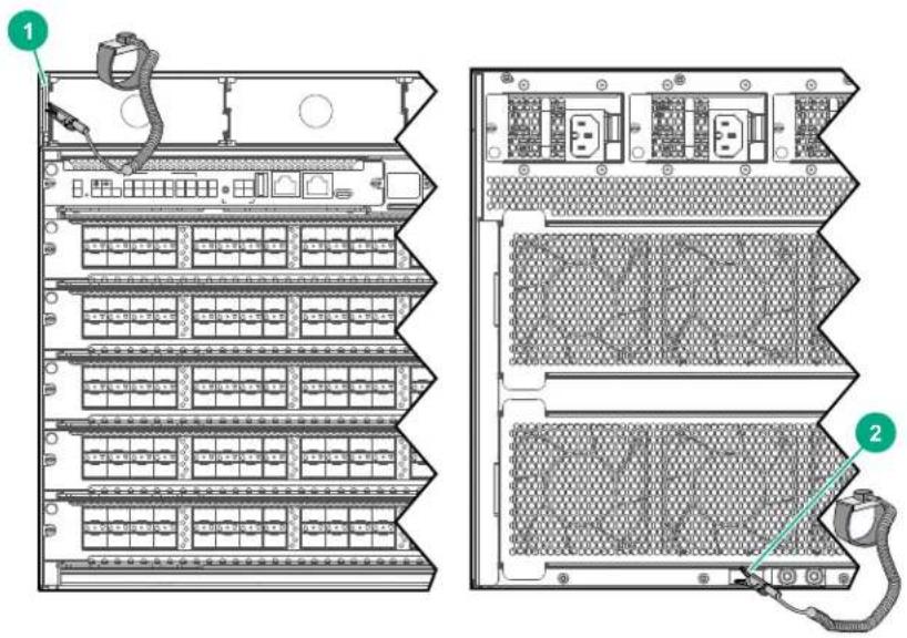
| 1 ESD wrist strap connection point on front panel. In this case, the connection point is the metal tab that is exposed when the bezel is removed. |
| 2 ESD wrist strap connection point (grounding lug) on rear panel |
- Hold management modules and line modules by their edges. Do not touch any electronic components or printed circuitry.
- Store uninstalled modules in antistatic bags.
Handle your Aruba 6400 Switch components with care. Rough or careless handling can damage the components and result in unplanned down time.
Installing a new power supply unit and AC inlet accessory in an empty slot
Prerequisites
Mount the 6400 chassis in a rack or other location as described in Mounting the switch.

IMPORTANT: A C16 AC inlet accessory is shipped with the R0X35A Aruba 6400 1800W Power Supply. A C20 AC inlet accessory is shipped with the Aruba 6400 3000W Power Supply. Using a C16 AC inlet accessory with a 3000W power supply, or using a C20 AC inlet accessory with an 1800W power supply is not supported.
Procedure
- If installed, remove the bezel from the front of the chassis to expose the four power supply slots.
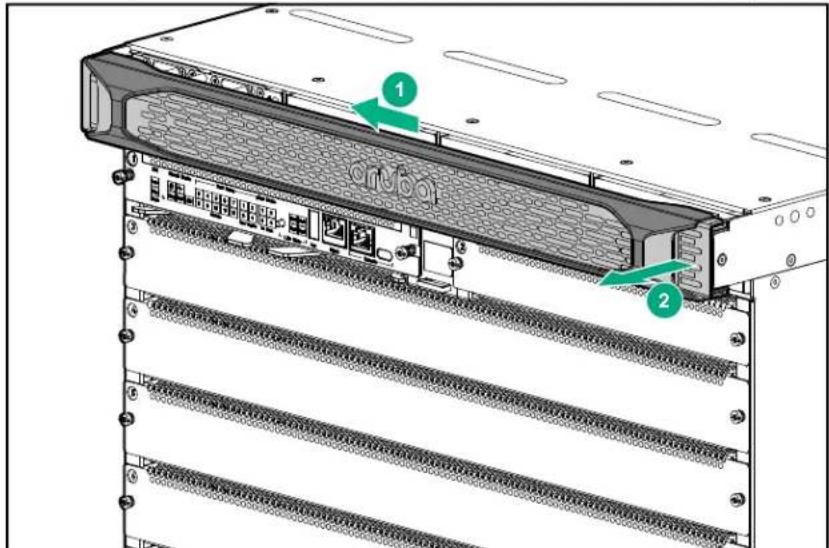
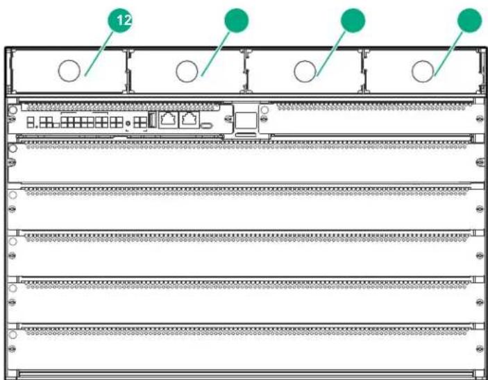
| 1 Power supply slot 1 and slot cover |
| 2 Power supply slot 2 and slot cover |
| 3 Power supply slot 3 and slot cover |
| 4 Power supply slot 4 and slot cover |
- Remove the slot cover from a power supply slot and store it for future use. In the following illustration, the slot cover is being removed from PSU slot 1.
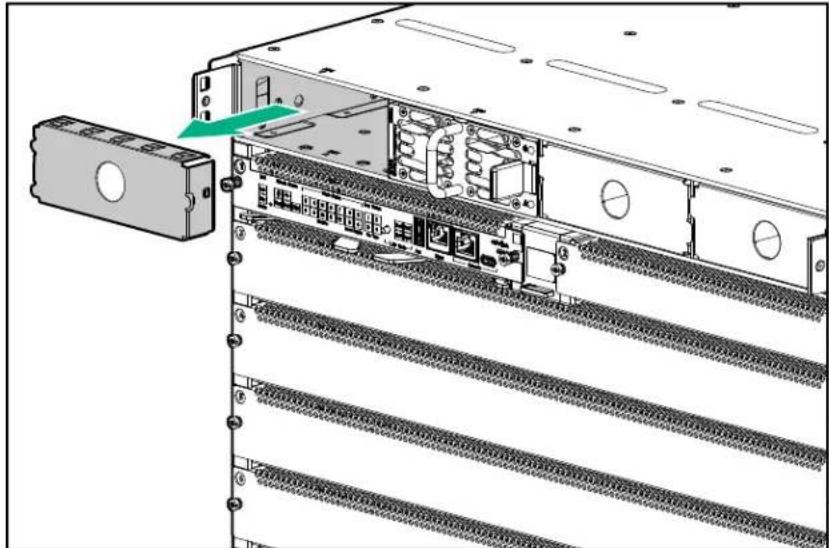
natural_image
Diagram of a server rack with internal components and a separate box, showing no text or symbols.- Slide the power supply unit half way into the open power supply slot.
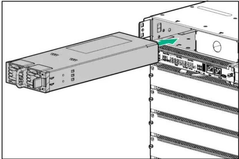
natural_image
Diagram of a server rack with an external drive and internal components, showing no text or symbols.-
Grasp the power supply handle and slide the unit into the slot until it clicks into place. The front of the power supply unit must be firmly seated, with the front of the unit flush with the front of the chassis.
-
On the rear of the chassis, remove the AC inlet accessory slot cover for the same slot number in which you installed the PSU in step 4.
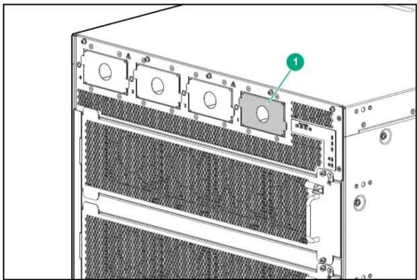
1 Power receptacle for power supply slot 1
- Grasp the AC inlet adapter handle and slide the unit into the slot until it clicks into place. Then tighten the retaining screw.
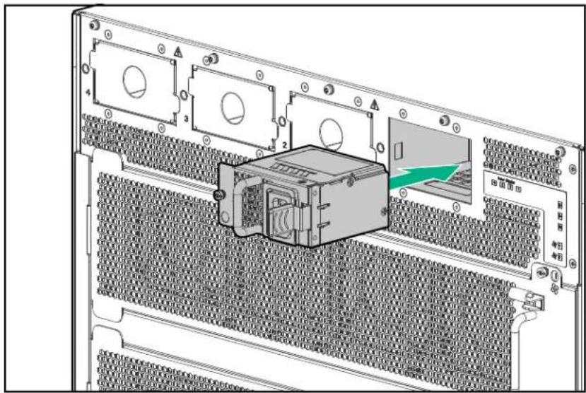
-
To install an additional power supply unit, repeat steps 2 through 6.
-
Replace the bezel on the chassis front panel.
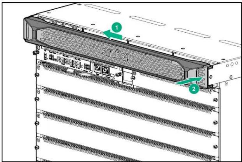
- Power-on and verify that the installed power supply units are running properly. A steady green LED on the front panel of a PSU indicates proper operation. (For more information on LED behavior, see the latest version of the Monitoring Guide at https://asp.arubanetworks.com/downloads.)

NOTE: The 6400 Series chassis and PSUs do not include a power on/off switch. PSUs are powered on by connecting the AC power cord at the rear of the chassis, and to an AC power source.
Install management modules in slots 1 and 2
Skip this task if your management modules are already installed.
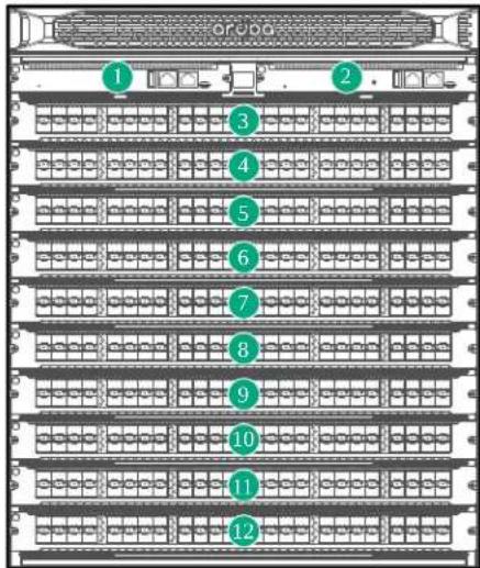
| Aruba 6405 and 6410 : 1 and 2 Management module slots | |
| Aruba 6405: 3 through 7Aruba 6410: 3 through 12 | Line module slots |
Procedure

CAUTION: Handle your Aruba 6400 switch management modules with care. Rough or careless handling can damage the modules and result in unplanned down time.
-
Put on an ESD wrist strap and properly ground it on the switch. See ).
-
Remove a management module slot cover (from slot 1 or 2) and store it for future use.
-
Install a management module in the uncovered slot.
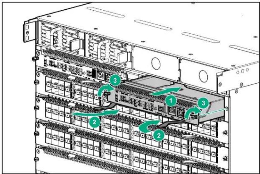
- Tighten the screws at each end of the module.
Install line modules
Procedure

CAUTION: Handle your Aruba 6400 switch line modules with care. Rough or careless handling can damage the modules and result in unplanned down time.
-
Put on an ESD wrist strap and properly ground it to the chassis. See Protect the switch and components from damage caused by ESD (Electrostatic discharge).
-
Remove a slot cover from a line module slot and store it for future use.
-
Seat a line module firmly in the uncovered slot.
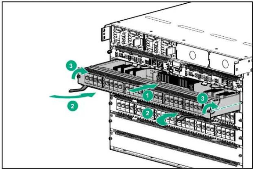
-
Pivot the locking levers into the closed position.
-
Tighten the restraining screws on each end of the module.
-
Repeat steps 1 through 3 for any additional line modules you want to install.

NOTE: If the switch configuration has no information about any module in a slot (i.e. in a default configuration, a line module installed in that slot boots up when power is applied. But if the slot is configured for a different type of line module than installed in the slot, then the installed line module does not boot up when power is applied. See Using controlled shut down to add or replace line modules.
Installing or removing transceivers

WARNING: The SFP and QSFP form-factor optical transceivers are Class 1 laser devices. Avoid direct eye exposure to the beam coming from the transmit port.

CAUTION:
- Use only supported, genuine HPE or Aruba transceivers with your switch. Consult Datasheets/Quickspecs for a list of supported transceivers and DACs. Use of non-supported transceivers may result in product malfunction. If you require additional transceivers, contact your authorized Aruba Sales representative.
- When handling line modules and transceivers, always wear an ESD wrist strap. Make sure it has snug skin contact and is reliably grounded.
- Do not remove the dust plug from a transceiver if you are not going to connect an optical fiber to it.
• Before installing a transceiver, first remove any connected optical fiber cable.
- To prevent particles from entering unused transceiver ports, keep dust plugs in any ports where a transceiver is not installed.
For information on Aruba optical transceivers and cable assemblies supported on your Aruba 6400 Switch, see the latest version of the ArubaOS-Switch and ArubaOS-CX Transceiver Guide at https://asp.arubanetworks.com/downloads.
You can install or remove SFP and QSFP form-factor transceivers without having to power off the switch.
Installing a transceiver
- Wear an ESD wrist strap with snug skin contact and reliable grounding. (See Attaching an ESD wrist strap.)
- Unpack the module. Hold it carefully by its sides. Avoid touching the plated contacts.
- Slide the transceiver into a slot until it clicks into place.
Removing a transceiver
- Wear an ESD wrist strap with snug skin contact and reliable grounding. (See Attaching an ESD wrist strap.)
- Disconnect the network cable from the transceiver before removing it from the module. Depending on when you purchased your transceiver, it may have either of three different release mechanisms: a plastic tab on the bottom, a wire bail, or a plastic collar.
- To remove the transceivers that have the plastic tab or plastic collar, push in the plastic tab or collar toward the switch until you see the transceiver release from the switch (you can see it move outward slightly), and then pull it from the slot.
-
To remove the transceivers that have the wire bail, lower the bail until it is approximately horizontal, then using the bail, pull the transceiver from the slot.
-
Place the transceiver in an ESD-protected container.
-
If you are leaving the transceiver slot empty, install a dust cover.
Fan trays are installed in the slots on the rear of the chassis.

CAUTION: For proper cooling and ventilation, a powered-up 6400 Series chassis must have all fan trays installed and all fans in each fan tray running. Do not remove a fan tray from a powered up switch without having a replacement fan tray available. When replacing a fan tray in an operating switch, install the replacement fan tray within two minutes of removing the original fan tray.

CAUTION: Replace only one fan tray at a time. Removing more than one fan tray at a time compromises system cooling, risks damage to the hardware, and can cause the switch to shut down abruptly.

CAUTION: Handle your Aruba 6400 switch fan trays with care. Rough or careless handling can damage these components and result in unplanned down time.

IMPORTANT: The Aruba 6405 Switch operates with two fan trays, and the Aruba 6410 switch operates with four fan trays. For proper air flow, ensure that all fan tray slots are occupied with fully functioning fan trays.
Procedure
-
Select an empty fan tray slot.
-
Insert a fan tray in the fan tray slot. The fan tray latch will sound an audible "click" when properly seated.
-
Tighten the two screws securing the fan tray in the slot.
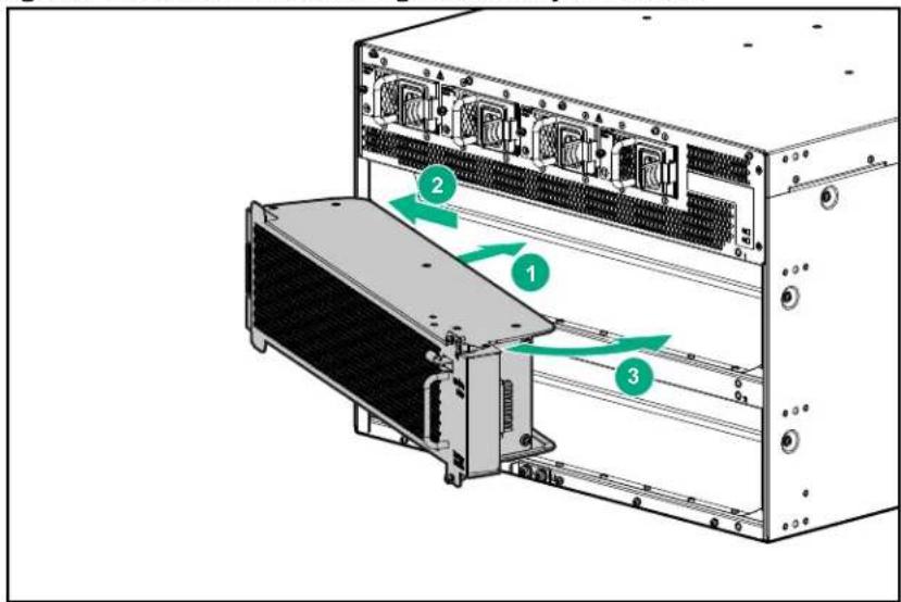
- To install another fan tray in another empty slot, repeat steps 1 through 3.
Installing the cable manager
The cable manager attaches through the rack mounting brackets to the rack for 2-post rack mounting. The cable manager attaches through the rack mounting brackets and the four-post mounting spacer for 4-post rack mounting.
Prerequisites
The switch is mounted in a four-post rack or with the rack mounting brackets in the front mounting position in a two post rack mount. (See the illustrations under Two-post rack mounting.)
Procedure
- Attach five cable retainers to each cable manager bulkhead, as shown.
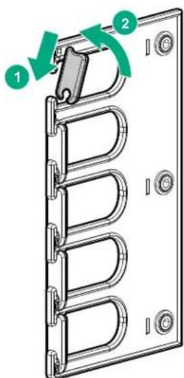
- Attach three angle brackets to each cable manager bulkhead. Use the screws provided. (The Aruba 6405 Switch is shipped with two cable manager bulkheads. The Aruba 6410 Switch ships with four cable manager bulkheads.)
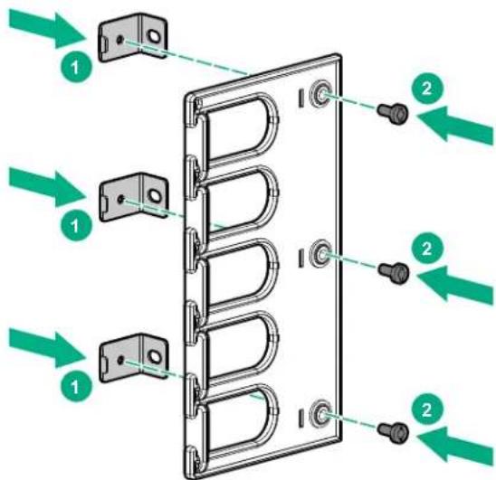
-
Install the cable restraints on the cable manager bulkheads, as shown in step 1.
-
Position the cable manager bulkheads over the rack mounting brackets so that the holes in the attached angle brackets line up with holes going through the rack mounting brackets to the screw holes in the rack posts. Install and tighten the screws to secure the cable manager bulkheads on the rack posts.
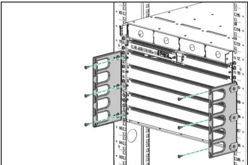
Power-on and boot-up
Prerequisites
Install the switch components as described in Installing components.
Procedure
- Plug the supplied power cords into the AC inlets on the rear panel of the chassis.

NOTE: The Aruba 6400 switches do not have a power switch. They are powered-on when the power cord is connected to the switch and to a power source.
- Plug the provided power cords into the AC power supplies for your switch. Each power cord should be plugged into a separate, dedicated, properly grounded 20-Amp circuit.

CAUTION: Do not plug multiple power supplies into the same circuit, as it may cause an overload condition.
-
Allow approximately five minutes for the switch to complete the NOS boot-up.
-
After the NOS boot-up completes, verify that the switch is operating properly by observing the LEDs. If you need a reference for interpreting LED behavior, see the Monitoring Guide by visiting the Aruba Support Portal at https://asp.arubanetworks.com/downloads.
Initial management access
Initial configuration of a factory default switch

NOTE: For detailed information on using the following initial configuration methods, see the Fundamentals Guide on the Aruba Support Portal at https://asp.arubanetworks.com/downloads
Use one of the following methods to perform the initial configuration:
- Zero Touch Provisioning (ZTP).
- Wireless connection through a mobile device using Bluetooth and the Aruba CX Mobile App. The wireless connection is achieved by plugging in the Bluetooth dongle to the USB slot, and then connecting using the Aruba CX Mobile application.

NOTE: The Bluetooth dongle is shipped with all Aruba CX switches.
- Connecting with SSH through the switch management port to a computer connected to the same network.
- Connecting the switch console port to a computer running terminal emulation software, and configuring switch settings by executing CLI commands.
Protect the switch and components from damage caused by ESD (Electrostatic discharge)

CAUTION:
• See Grounding the chassis.
• Always wear an ESD wrist strap when handling the switch or its components. Ensure the strap is reliably grounded to an unpainted metal grounding point when installing or removing switch components.
Figure 26: Unpainted surfaces on the switch make good grounding points for the ESD strap
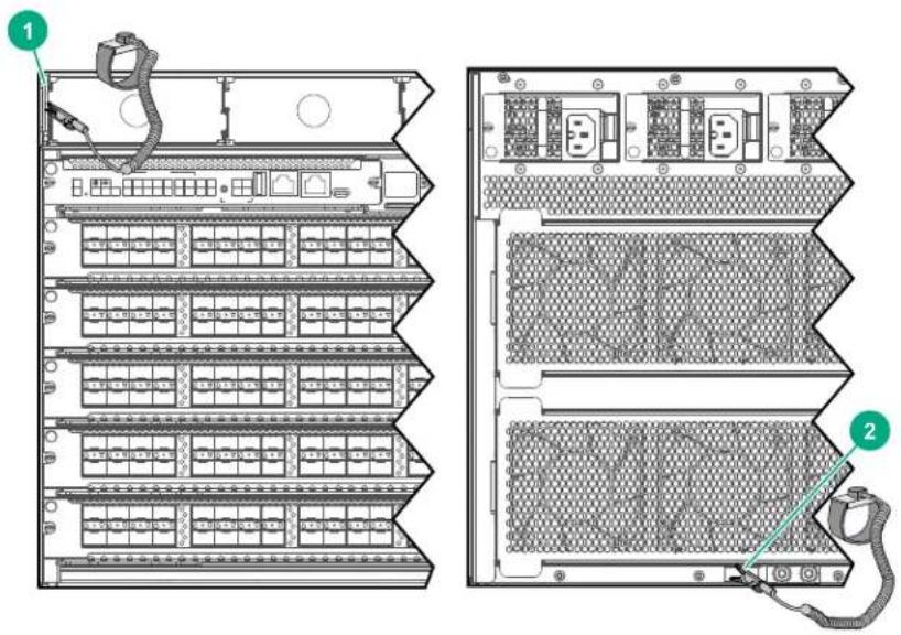
| 1 ESD wrist strap connection point on front panel. In this case, the connection point is the metal tab that is exposed when the bezel is removed. |
| 2 ESD wrist strap connection point (grounding lug) on rear panel |
- Hold management modules and line modules by their edges. Do not touch any electronic components or printed circuitry.
- Store uninstalled modules in antistatic bags.
Handle your Aruba 6400 Switch components with care. Rough or careless handling can damage the components and result in unplanned down time.
Adding or replacing line modules with controlled shutdown or hot swap methods
Aruba recommends using the CLI to shut down modules before removing them from the switch. This provides a controlled shutdown process that minimizes traffic loss and loss of function. However it also can cause a longer delay in getting the replacement module operational.

IMPORTANT: Unplanned hot swapping of modules is also supported, though it can result in traffic loss and some system interruption. Unplanned line card hot swap is enabled for a single card at a time with at least one minute required between unplanned hot swaps of multiple line cards.
Using controlled shut down to add or replace line modules
If an empty line module slot is in the default configuration state, a module boots up when installed in the slot. If there is a configuration mismatch between an installed module and the slot in which it is installed, the module does not boot up. Use the procedures in this section to bring up a line module in cases where the slot configuration is a mismatch for the line module.
Adding a line module to an empty, unconfigured slot
Prerequisites
- Have an ESD wrist strap ready to use.
- Have available the line module you plan to install in the empty, unconfigured slot. When installing a line module in an unconfigured slot, the module will be brought up as Admin-state up.
- Know the configuration you want on the selected slot.
Procedure
- Put on a snugly fitting ESD wrist strap and attach it to the ESD connector on the front of the switch. (See Protect the switch and components from damage caused by ESD (Electrostatic discharge).)
- Remove the blank slot cover from the chosen slot and store it for future use.
- Install the module. As noted above, installing a line module in an unconfigured slot brings the module up as Admin-state up.
Removing or replacing a line module

NOTE: If you are exchanging one type of line module with a different type in the same slot, or not replacing the module at all, reset the slot to the default configuration by using the no module

IMPORTANT: When removing or installing line modules, make sure to wear a properly installed ESD wrist strap to avoid damage to the line card. See Attaching an ESD wrist strap for more information.
Prerequisites
Have the replacement line module available and ready to install.
Procedure
- Use the module
admin-state down command to bring down the module slot before removing the installed module.
For example, to bring down module slot 1/2:
switch(config)# module 1/2 admin-state down
- Before removing the module, verify that it is down using the show module
command.
For example, to show the module in slot 1/2:
switch(config)# show module 1/2
Line module 1/2 is down: (Administratively down)
Description: 6400 24P SFP+ and 4P SFP56 Mod
Full Description: 6400 24-port SFP+ and 4-port SFP56 Module
Serial number: xxxxxxxxxx
Product number: R0X43A
-
Loosen the screws securing the line module to the chassis.
-
Open the extractor handles and pull the module out of its slot, placing the module in an antistatic bag for protection from ESD damage.
-
If you do not plan to install another line module in the empty slot, then secure a line module slot cover over the slot opening.
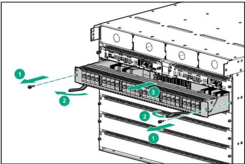
- To install another line module in the empty slot:
a. Slide the line module part-way into the selected module slot.
b. Open the extractor handles.
c. Push the module into the slot until it stops.
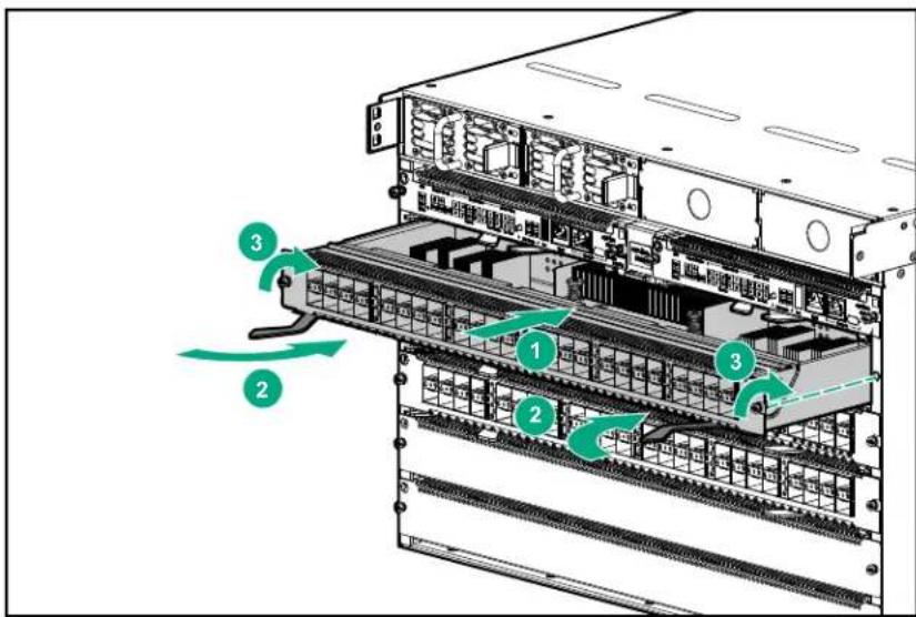
d. Firmly close the extractor handles.
e. Tighten the screws at the top and bottom of the module.
-
If you are replacing the module with a module of a different type, use the no module
command to set the slot to its default configuration and then reconfigure the slot for the new module type. See the Fundamentals Guide for more information. -
If the replacement module is the same type as the original module, use the module
admin-state up command to bring up the module slot. The original configuration will be maintained.
For example, to bring up module slot 1/2:
switch(config)# module 1/2 admin-state up
- Verify that the module successfully booted and is operational using the show module
command.
For example, to show the module in slot 1/2:
switch(config)# show module 1/2
Line module 1/2 is up:
Description: 6400 24P SFP+ and 4P SFP56 Mod
Full Description: 6400 24-port SFP+ and 4-port SFP56 Module
Serial number: xxxxxxxxxx
Product number: R0X43A
Removing or replacing a standby management module
Prerequisites
If you are replacing the standby module, have the replacement available and ready to install.
Procedure
-
Put on an ESD wrist strap and connect it to the ESD connection point on the front of the chassis. (See Attaching an ESD wrist strap.)
-
Identify the standby Management module.
The Stby LED shows a solid green and the Actv LED is dark.
-
Loosen the screws securing the standby module to the chassis.
-
Open the module levers and pull the module out of its slot. To help protect the module from ESD damage, place it in an anti-static bag.
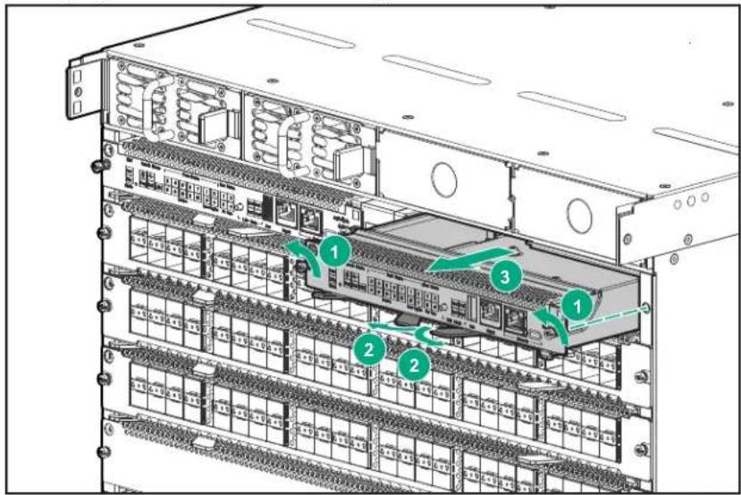
-
If you do not plan to install another management module in the empty slot, then secure a management module slot cover over the slot opening.
-
To install another management module in the empty slot:
a. Slide the management module part-way into the standby Management module slot. (The installed management module showing the lighted Actv LED indicates the active slot).
b. Open the module locking levers.
c. Push the module into the slot until it stops.
d. Firmly close the module locking levers.
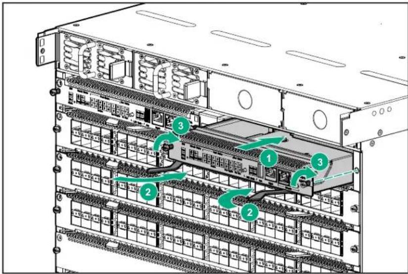
e. Tighten the screws at the top and bottom of the module.
Removing or replacing an active management module

NOTE: To remove an active management module, both a standby and an active management module must be installed in the switch. If there is only one management module installed, then install your replacement module as a standby module before performing this procedure. (See Removing or replacing a standby management module.)
To remove the active management module from the switch, first use the redundancy-switchover command to convert the active module to standby and the standby module to active.
Prerequisites
If you are replacing the active management module, have the replacement module available and ready to install.
Procedure
-
Put on an ESD wrist strap and connect it to the ESD connection point on the front of the chassis. (See Attaching an ESD wrist strap.)
-
Identify the active management module. (The Mgmt State Activ LED shows solid green to indicate the active management module.)
-
Using the CLI, execute the redundancy-switchover command to convert the active management module to standby, and the standby management module to active.
For more information on module commands, see the Command-Line Interface Guide.

NOTE: After using the redundancy-switchover command, check the Active and Standby LEDs on both modules to ensure that the Active/Standby conversion took place. If the Standby management module was not available when the command was executed, the conversion fails.
-
Loosen the screws securing the module you converted to Standby in step 3.
-
Open the locking module levers and pull the module out of its slot. Place the module in an antistatic bag for protection from ESD damage.
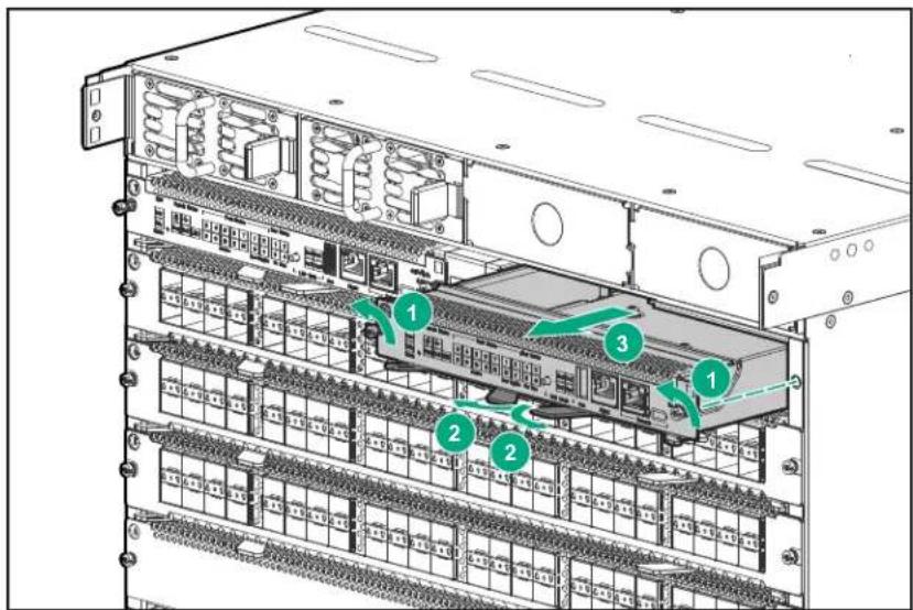
- If you do not plan to install another management module in the empty slot, then secure a management module slot cover over the slot opening.
Fan trays are installed in the slots on the rear of the chassis.

CAUTION: Replace only one fan tray at a time. Removing more than one fan tray at a time compromises system cooling, risks damage to the hardware, and can cause the switch to shut down abruptly.

CAUTION: For proper cooling and ventilation, a powered-up 6400 Series chassis must have all fan trays installed and all four fans in each fan tray running.
- Do not remove a fan tray from a powered up switch without having a replacement fan tray available.
- When replacing a fan tray in an operating switch, install the replacement fan tray within two minutes of removing the original fan tray.
- Ensure that all fans in the replacement fan tray are operating after installation.
- If replacing more than one fan tray, ensure each fan tray is correctly installed and operational before removing the next fan tray.
Figure 27: Aruba 6405 rear panel with two fan trays
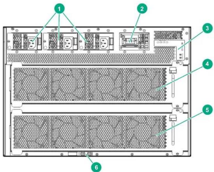
| 1 Installed AC inlet accessories PSU slots 2 - 4 |
| 2 Open AC inlet accessory slot for PSU slot 1 |
| 3 Rear panel LEDs |
| 4 Fan tray installed in fan tray slot 1 of the Aruba 6405 Switch |
| 5 Fan tray installed in fan tray slot 2 of the Aruba 6405 Switch |
| 6 Grounding lug |
Prerequisites
- For an Aruba 6405 Switch, ensure that there will be one fully functional fan tray operating after you remove the fan tray you are replacing.
- For an Aruba 6410 Switch, ensure that there will be three fully functional fan trays operating after you remove the fan tray you are replacing.
- Unpack the replacement fan tray and place it on an antistatic surface.
- Put on an ESD wrist strap and properly ground it on the switch. See Protect the switch and components from damage caused by ESD (Electrostatic discharge).
- Select the fan tray to remove.
-
Loosen the two retaining screws securing the fan tray to the chassis.
-
Depress and hold the fan tray latch, grasp the handle below the latch, and pull the handle to pivot the fan tray out of the slot.
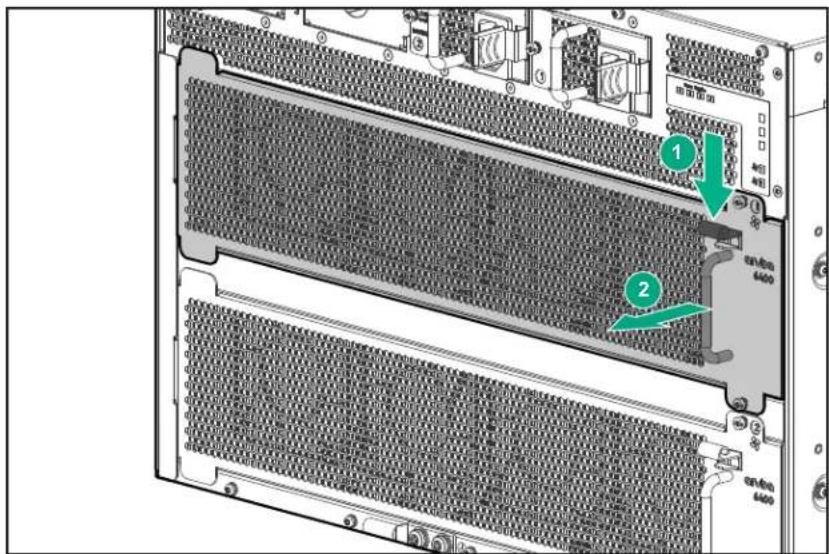
- Shift the fan tray to the right to disengage it from the chassis.
Installing the replacement fan tray
Prerequisites
- Have the replacement fan tray available and ready to install.
-
Remove the fan tray you are replacing. See Removing the fan tray
-
Line the fan tray up with the empty slot.
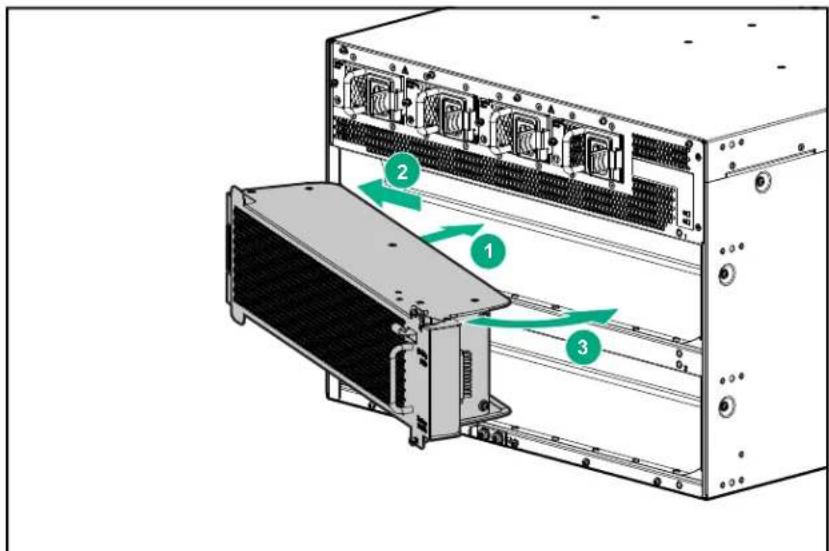
- Insert the fan tray into the slot at an angle as shown.
-
Seat the left end of the fan tray behind the flange on the left side of the slot.
-
Pivot the right end of the fan tray into the slot.
- Tighten the two screws on the right end of the fan tray to secure it in the slot.
- Store the replaced fan tray in an antistatic bag for ESD protection.
Protect the switch and components from damage caused by ESD (Electrostatic discharge)

CAUTION:
• See Grounding the chassis.
• Always wear an ESD wrist strap when handling the switch or its components. Ensure the strap is reliably grounded to an unpainted metal grounding point when installing or removing switch components.
Figure 28: Unpainted surfaces on the switch make good grounding points for the ESD strap
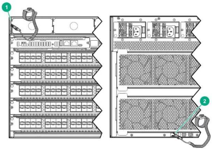
| 1 ESD wrist strap connection point on front panel. In this case, the connection point is the metal tab that is exposed when the bezel is removed. |
| 2 ESD wrist strap connection point (grounding lug) on rear panel |
- Hold management modules and line modules by their edges. Do not touch any electronic components or printed circuitry.
- Store uninstalled modules in antistatic bags.
Handle your Aruba 6400 Switch components with care. Rough or careless handling can damage the components and result in unplanned down time.
Basic troubleshooting tips
The following situations cause most problems. Check for these items first when starting your troubleshooting:
- Faulty or loose cables. Look for loose or faulty connections. If they appear to be OK, make sure that the connections are snug. If that does not correct the problem, try a different cable.
- Non standard cables. Non standard and mis-wired cables may cause network collisions and other network problems, and can seriously impair network performance. Use a new, correctly wired cable. For pinouts and correctly wired cable, compare your cable to the cable information in the latest version of the ArubaOS-Switch and ArubaOS Transceiver Guide at https://asp.arubanetworks.com/downloads. A category 5 cable tester is a recommended tool for every 1000Base-T network installation.
- Improper Network Topologies. It is important to ensure that you have a valid network topology. Common topology faults include excessive cable length and excessive repeater delays between end nodes. If you have network problems after recent changes to the network, change back to the previous topology. If you no longer experience the problems, the new topology is likely at fault.
In addition, make sure that your network topology contains no data path loops. Between any two end nodes, there must be only one active cabling path at any time. Data path loops cause broadcast storms that severely impact your network performance.
Building redundant paths between important nodes in your network provides some fault tolerance. Before opening redundant paths, enable Spanning Tree Protocol support on the switch. Spanning tree ensures that only one of the redundant paths is active at any time, thus avoiding data path loops. Spanning Tree can be enabled through the switch console or the web browser interface.
The 6400 switches also support Trunking (link aggregation), which allows using multiple network cables for a single network connection without causing a data path loop. For more information, go to https://asp.arubanetworks.com/downloads and see these publications:
- Spanning Tree: Layer 2 Bridging Guide
- Trunking: Link Aggregation Guide
- Using event and debug logs, show tech, and run-time diagnostics. These built-in features can help to isolate the sources of problems. For more information, see the Diagnostics and Supportability Guide at https://asp.arubanetworks.com/downloads.
Functions of the management module reset button

CAUTION: Use a hard reset on a management module only if other methods to recover from a loss of control have failed. Using a hard reset can result in corrupting the file system on the management module SSD (solid state drive). In this case, reformatting the management module SSD is required to recover.
| Module Soft reset: Press Reset button for less than five seconds | Hard reset: Press Reset button for five seconds or more | |
| Module "A" Active | Resets management module "A" after a 5-10 second delay for orderly shutdown.Failureover occurs. Module "A" becomes the Standby after it comes back up.Module "B" (the former Standby management module) becomes the new Active management module and maintains switch operation.If there is no Standby management module installed, or if the installed Standby module is inoperative, then the switch goes down while module "A" completes the reset process and resumes operation as the Active management module. | Immediately resets management module "A". There is no shutdown process. This action can result in a loss of data that was currently being processed in module "A".Management module "B" does not reset; becomes the new Active management module.If there is no second module installed, or if the installed second module is inoperative, then the switch goes down while management module "A" completes the reset process and resumes operation. |
| Module "B" Standby | Resets management module "B" during a 5-10 second reset delay for orderly shutdown.The switch remains up and running.Management module "B" returns to the Standby role when it completes its reset cycle.No effect on the Active management module (Module "A").NOTE: If a condition that causes a failover occurs while Module "B" is still in its reset cycle, a full chassis restart results. | Immediately resets management module B. There is no orderly shutdown process.Management module "B" resumes as the Standby management module after the reset concludes.No effect on the Active management module (Module "A"). |
PSU output ratings
Table 12: Aruba 6400 PSU inlet support matrix
| PSU and inlet accessory type | Output at 110-127/VAC | Output at 200-240VAC | Support |
| 3000W PSU connected to a C20 inlet adapter | 1500W 3000W | Supported combination. | |
| 3000W PSU connected to a C16 inlet adapter | 1100W 1800W | Not supported. Use may affect power redundancy. | |
| 1800W PSU connected to a C16 inlet adapter | 1100W 1800W | Supported combination. | |
| 1800W PSU connected to a C20 inlet adapter | 1100W 1800W | Not supported. Use may affect power redundancy. |

NOTE: Using a C16 inlet adapter with a 3000W PSU, or using a C20 inlet adapter with an 1800W PSU is not supported.
System power consumption
To determine the maximum power consumption of an Aruba 6400 switch, determine the quantity of each component installed in the table titled "Component power usage". Multiply the quantity installed by the "Power per component" to determine the total power consumption of each component type. Sum the total of all component types to determine the total maximum power consumption for the system.
Table 13: Base chassis power consumption
| Switch SKU and model Included/installed components Power | ||
| ROX26A Aruba 6405 Switch | One 7-slot base system chassis (ROX24A) | 645W |
| Two management modules (ROX31A) | ||
| Two fan trays | ||
| ROX27A Aruba 6410 Switch | One 12-slot base system chassis (ROX25A) | 1194W |
| Two management modules (ROX31A) | ||
| Four fan trays | ||
Table 14: Component power usage
| SKU 6400 Component Power per component | ||
| ROX38B Aruba | 6400 48-port 1GbE Class 4 PoE Module 113W | |
| ROX39B Aruba | 6400 48-port 1GbE Class 4 PoE and 4-port SFP56 Module 121W | |
| ROX40B Aruba | 6400 48-port 1GbE Class 6 PoE and 4-port SFP56 Module 121W | |
| ROX41A Aruba | 6400 48-port HPE Smart Rate 1/2.5/5GbE Class 6 PoE and 4-port SFP56 Module | 249W |
| ROX42A Aruba | 6400 24-port 10GBASE-T and 4-port SFP56 Module 240W | |
| ROX43A Aruba | 6400 24-port SFP+ and 4-port SFP56 Module 156W | |
| ROX44A Aruba | 6400 48-port 10/25GbE SFP28 Module 424W | |
| ROX45A Aruba | 6400 12-port 40/100GbE QSFP28 Module 352W | |
Table 15: Available power from PSUs installed
| Number of PSUs | 3000W PSU (R0X36A) @ 200-240 VAC1 | 3000W PSU (R0X36A) @ 110 - 127 VAC | 1800W PSU (R0X35A) @ 200-240 VAC | 1800W PSU (R0X35A) @ 110-127 VAC |
| 1 3000 | W 1500W 1800W 1100W | |||
| 2 5940 | W 2970W 3564W 2178W | |||
| 3 8880 | W 4440W 5328W 3256W | |||
| 4 11820 | W 5910W 7092W 4334W |
1 Power is reduced to 2950 at 200VAC nominal. This primarily applies to Japan, as they are the only country with a 200VAC high line. However, the power drop can also occur in other electrical environments where the high line power drops to 200VAC for any reason.

NOTE: Power consumption numbers reflect worst case conditions under maximum traffic loading. In practice actual power consumption is typically less than these limits.
These power consumption limits are used by the management software to determine how much power to allocate for each module. If there is not enough available power for all line cards installed, the management software may not power all cards to stay below the available power.
Power available for PoE: Excess power available from the power supplies beyond the total system and line module allocation is available for PoE powered devices sourced by the line modules.
Redundancy: If power supply or AC grid redundancy is required, add additional power supplies to the system.
Example using an Aruba 6405:
- Installed components:
- Two 1800W PSUs @ 200-240 VAC (high line)
- Two management modules
- All fan trays installed
•Four R0X38B Aruba 6400 48p 1G CLS 4 Mod
•One R0X45A Aruba 6400 12p 40G/100G QSFP28 Mod
- System power required: 645W + (4× 113W) + (1× 352W) = 1449W
• Available power: 2 x 1800W = 3564W (see Table 15: Available power from PSUs installed) - Excess power available for PoE: 3564W -- 1449W = 2115W
- If power supply redundancy is required:
• Available power comes from one less PSU, which equals 1800W.
- Excess power available for PoE is: 1800W -- 1449W = 351W.
Aruba 6400 switch acoustics information
| Measurement configuration Acoustics | |
| Aruba 6405 with one Management module installed• Two line modules (R0X39B, R0X38B)• Two 3000W PSUs (R0X36A)• 370W PoE delivered• Traffic on all ports | Sound power ( L_WAd ): 6.5 BelSound Pressure ( L_pAm , Bystander): 46.3 dB |
| Aruba 6405 with one Management module installed• 2 line modules (R0X39B, R0X38B)• Two 1800W PSUs (R0X35A)• 370W PoE delivered• Traffic on all ports | Sound Power ( L_WAd ): 6.6 BelSound Pressure ( L_pAm , Bystander): 46.6 dB |
| Aruba 6410 with one Management module installed• Two line modules (R0X39B, R0X38B)• Two 3000W PSUs (R0X36A)• 370W PoE delivered• Traffic on all ports | Sound power ( L_WAd ): 6.8 BelSound Pressure ( L_pAm ): 48.9 dB |
| Aruba 6410 with one Management module installed• 2 line modules (R0X39B, R0X38B)• Two 1800W PSUs (R0X35A)• 370W PoE delivered• Traffic on all ports | Sound Power ( L_WAd ): 6.8 BelSound Pressure ( L_pAm , Bystander): 48.8 dB |
Aruba 6400 product weights
| SKU 6400 Product Weight Ibs Weight Kg | |||
| ROX24A 6405 chassis 44.5 lbs 20.2 | |||
| ROX25A 6410 chassis 82.7 lbs 37.5 | |||
| ROX35A 1800W PSU 3.7 lbs 1.7 | |||
| ROX36A 3000 PSU 3.9 lbs 1.8 | |||
| N/A PSU slot blank 0.07 0.03 | |||
| ROX31A Management module 2.6 1.2 | |||
| N/A Management module blank 0.5 0.2 | |||
| ROX38B 48-port 1G Class 4 PoE Module | 6.25 2.83 | ||
| ROX39B 48-port 1G Class 4 PoE & 4-port SFP56 Module | 6.45 2.92 | ||
| ROX40B 48-port 1G Class 6 PoE & 4-port SFP56 Module 6.6 | 2.99 | ||
| ROX41A 48-port SR Class 6 PoE & 4-port SFP56 Module | 7.6 | 3.45 | |
| ROX42A 24-port SR & 4-Port SFP56 Module | 6.6 | 2.99 | |
| ROX43A 24-port SFP+ & 4-port SFP56 Module | 6.2 | 2.81 | |
| ROX44A 48-port 10G/25G SFP28 Module | 9.3 | 4.22 | |
| ROX45A 12-port-port 40G/100G QSFP28 Module | 8.65 3.92 | ||
| N/A Line module blank | 1.1 | 0.50 | |
| N/A AC inlet accessory 0.4 0.18 | |||
| N/A AC inlet slot blank | 0.004 | 0.002 | |
Product dimensions
| Space | 6405 | 6410 |
| Width without rack mounting brackets | 442.6 mm (17.4 in) | 442.6 mm (17.4 in) |
| Height | 306.6 mm (12.1 in) | 528.8 (20.8 in) |
| Depth (includes installed cable manager and inlet accessories) | 592.5 mm (23.3 in) | 592.5 mm (23.3 in) |
| Space to remove or install fan tray | 279.4 mm (11 in) | 279.4 mm (11 in) |
| Install or remove a line card | 381 mm (15 in) | 381 mm (15 in) |
Table 16: Environmental specifications for 6400 switch models
| Item Range | |
| Operating Temperature: 0° to +45°C (+32°F to | +113°F) up to 5000 ft; derate -1°C for every 1000 ft from 5000 ft to 10000 ft |
| Non-Operating Temperature: -40° to +70°C (-40°F to +158°F) up to 15000 ft | |
| Operating Relative Humidity: 15% to 95% at 45°C (104°F) non-condensing | |
| Non-Operating Storage Relative Humidity: 15% to 95% @ 65°C (149°F) non-condensing | |
| Maximum Operating Altitude: 3.05 km (10,000 ft) above sea level | |
 NOTE:Above 5,000 ft, operating temperature is derated by 1°C (1.8°F) per 305m (1000 ft). NOTE:Above 5,000 ft, operating temperature is derated by 1°C (1.8°F) per 305m (1000 ft). | |
| Maximum Non-Operating Altitude: 4.57 km (15000 ft) above sea level | |
Table 17: Safety and regulatory information for Aruba 6400 switches
| Topic Range | |
| Safety-EU: EN 60950-1:2006 +A11:2009 +A1:2010+A12:2011 +A2:2013EN62368-1, Ed.2 | |
| Safety-World Wide: IEC 60950-1:2005 Ed.2; Am 1:2009+A2:2013IEC62368-1, Ed. 2IEC 60825-1:2014 (Applies to products with lasers) | |
| North American: UL60950-1, CSA 22.2 No 60950-1UL62368-1 Ed. 2 | |
| Lasers: EN60825-1:2014 / IEC 60825-1:2014 Class 1Class 1 Laser Products / Laser Klasse 1 |
Table 18: Electrical information for Aruba modular power supplies using direct AC voltage
| Switch product SKU Maximum current AC voltage Frequency range | |||
| Any Aruba 6405 Switch populated with the R0X35A 1800W power supplies and C16 inlet modules | 12A for 110-127VAC10A for 200-240VAC | 110-127200-240 | 50/60 HZ |
| Any Aruba 6405 Switch populated with the R0X36A 3000W power supplies and C20 inlet modules | 16A for 110-127VAC16A for 200-240VAC | ||
| Any Aruba 6410 Switch populated with the R0X35A 1800W power supplies and C16 inlet modules | 12A for 110-127VAC10A for 200-240VAC | ||
| Any Aruba 6410 Switch populated with the R0X36A 3000W power supplies and C20 inlet modules | 16A for 110-127VAC16A for 200-240VAC | ||
Additional regulatory information
For important safety, environmental, and regulatory information, see Safety and Compliance Information for Server, Storage, Power, Networking, and Rack Products, available at http://www.hpe.com/support/Safety-Compliance-EnterpriseProducts.
Networking Websites
Aruba Support Portal
asp.arubanetworks.com
Aruba Software and Documentation
asp.arubanetworks.com/downloads
Aruba Security Advisories
www.arubanetworks.com/support-services/security-bulletins
Hewlett Packard Enterprise Networking Software
www.hpe.com/networking/software
Hewlett Packard Enterprise Networking website
www.hpe.com/info/networking
Hewlett Packard Enterprise My Networking website
www.hpe.com/networking/support
Hewlett Packard Enterprise My Networking Portal
www.hpe.com/networking/mynetworking
Hewlett Packard Enterprise Networking Warranty
www.hpe.com/networking/warranty
General websites
Hewlett Packard Enterprise Information Library
www.hpe.com/info/EIL
Accessing Aruba Support
To access Aruba Support, go to https://www.arubanetworks.com/support-services/.
Be sure to collect the following information before contacting Support:
• Technical support registration number (if applicable)
- Product name, model or version, and serial number
- Operating system name and version
- Firmware version
- Error messages
• Product-specific reports and logs
- Add-on products or components
• Third-party products or components
Accessing updates
To download product updates:
Aruba Support Portal
asp.arubanetworks.com/downloads
If you are unable to find your product in the Aruba Support Portal, you may need to search My Networking, where older networking products can be found:
My Networking
www.hpe.com/networking/software
To view and update your entitlements, and to link your contracts and warranties with your profile, go to the Hewlett Packard Enterprise Support Center More Information on Access to Support Materials page:
www.hpe.com/support/AccessToSupportMaterials

IMPORTANT: Access to some updates might require product entitlement when accessed through the Hewlett Packard Enterprise Support Center. You must have an HP Passport set up with relevant entitlements.
Some software products provide a mechanism for accessing software updates through the product interface. Review your product documentation to identify the recommended software update method.
To subscribe to eNewsletters and alerts:
www.hpe.com/support/e-updates
Warranty information
To view warranty information for your product, go to https://www.hpe.com/support/Networking-Warranties.
Regulatory information
To view the regulatory information for your product, view the Safety and Compliance Information for Server, Storage, Power, Networking, and Rack Products, available at the Hewlett Packard Enterprise Support Center:
www.hpe.com/support/Safety-Compliance-EnterpriseProducts
Additional regulatory information
Hewlett Packard Enterprise is committed to providing our customers with information about the chemical substances in our products as needed to comply with legal requirements such as REACH (Regulation EC No 1907/2006 of the European Parliament and the Council). A chemical information report for this product can be found at:
www.hpe.com/info/reach
For Hewlett Packard Enterprise product environmental and safety information and compliance data, including RoHS and REACH, see:
www.hpe.com/info/ecodata
For Hewlett Packard Enterprise environmental information, including company programs, product recycling, and energy efficiency, see:
www.hpe.com/info/environment
Documentation feedback
Hewlett Packard Enterprise is committed to providing documentation that meets your needs. To help us improve the documentation, send any errors, suggestions, or comments to Documentation Feedback (docsfeedback@hpe.com). When submitting your feedback, include the document title, part number, edition, and publication date located on the front cover of the document. For online help content, include the product name, product version, help edition, and publication date located on the legal notices page.
- Aruba 6400 Switch Series Installation and Getting Started Guide
- Notices
- Chapter 1 About this document....6
- Chapter 2 Installation precautions and guidelines....8
- Chapter 3 Site preparation....12
- Chapter 4 Introducing the Aruba 6400 switch series....21
- Chapter 5 Unpacking, lifting, and moving the chassis....41
- Chapter 6 Mounting the switch....50
- Chapter 7 Installing components....69
- Chapter 8 Activating the switch....80
- Chapter 9 Adding or replacing switch components....81
- Chapter 10 Troubleshooting....91
- Chapter 11 Specifications....94
- Chapter 12 Safety and regulatory information....98
- Chapter 13 Websites.... 100
- Chapter 14 Support and other resources....101
- Applicable products
- Base Product SKU Description
- Latest version available online
- Related publications
- WARNING:
- CAUTION:
- Space
- Safety recommendations
- Electricity safety
- Handling safety
- Preventing electrostatic discharge damage
- Laser safety
- Examining the installation site
- Temperature
- Humidity
- Cleanliness
- EMI
- Grounding
- Power
- Procedure
- Cooling
- Product weight support
- Recommended screwdrivers for switch installation
- Shipping a rack-mounted Aruba 6400 switch chassis
- Overview of the Aruba 6400 switch
- Key features
- Physical dimensions, weight, and mounting
- Switch configurations
- Front of the switch
- Management module (MM) slots
- Management module specifications
- Management module LEDs
- Power supply units (PSUs) and slots
- PSU LEDs
- PSU bezel
- PSU slot cover
- Line module (LM) slots
- Line module specifications
- Line module LEDs
- Power cords and inlet adapters
- IMPORTANT:
- Rear of the switch
- Fan trays
- Fan tray
- Rear panel LEDs
- Power cords, power inlet accessories, and power supplies
- Power cord information
- 1800W PSU C15 Power cord information
- 3000W PSU C19 Power cord information
- Power over Ethernet (PoE) operation
- Ethernet Alliance PoE Certified
- Aruba 6400 PoE operation includes these features:
- Switch software features
- Unpacking the switch components
- Prerequisites
- Attaching an ESD wrist strap
- Removing installed components from the chassis
- Remove installed power supply units
- Remove any installed line modules
- Remove the fan trays
- Move the chassis to the mounting location
- Manually moving the chassis
- NOTE:
- Using a mechanical lift to move the chassis
- (Optional) Installing the chassis in a non-rack mounted position
- Manually positioning the chassis on a non-rack mount surface
- Using a mechanical lift to position the chassis on a non rack mount surface
- Mounting the chassis in a rack
- Two-post rack mounting
- Preparing the chassis for a two-post rack mounting
- Manually mounting the chassis in a two-post rack
- Go to Grounding the chassis
- Using a mechanical lift to mount the chassis in a two-post rack
- Four-post rack mounting
- Preparing the chassis for an optional four-post rack mount
- Installing the optional R0X37A Aruba 6400 4-post Rack Mount Kit
- Installing rack rails
- Installing rail spacers and front rack mounting brackets for the four-post rack mounting
- Installing rear support hardware on the chassis and four-post rack
- Manually mounting the chassis in the four-post rack
- Using a mechanical lift to mount the chassis in a four-post rack
- Go to Grounding the chassis.
- Grounding the chassis
- Grounding lug
- Protect the switch and components from damage caused by ESD (Electrostatic discharge)
- Installing a new power supply unit and AC inlet accessory in an empty slot
- Install management modules in slots 1 and 2
- Install line modules
- Installing or removing transceivers
- Installing a transceiver
- Removing a transceiver
- Installing the cable manager
- Power-on and boot-up
- Initial management access
- Initial configuration of a factory default switch
- Adding or replacing line modules with controlled shutdown or hot swap methods
- Using controlled shut down to add or replace line modules
- Adding a line module to an empty, unconfigured slot
- Removing or replacing a line module
- Removing or replacing a standby management module
- Removing or replacing an active management module
- Installing the replacement fan tray
- Basic troubleshooting tips
- Functions of the management module reset button
- PSU output ratings
- System power consumption
- Example using an Aruba 6405:
- Additional regulatory information
- Accessing Aruba Support
- Accessing updates
- Warranty information
- Regulatory information
- Documentation feedback
Brand : Aruba
Model : 6405
Category : Network card / adapter