
AVB-VSTYLE-POLE-MNT - Professional audiovisual equipment AMX - Free user manual and instructions
Find the device manual for free AVB-VSTYLE-POLE-MNT AMX in PDF.


User questions about AVB-VSTYLE-POLE-MNT AMX
0 question about this device. Answer the ones you know or ask your own.
Ask a new question about this device
Download the instructions for your Professional audiovisual equipment in PDF format for free! Find your manual AVB-VSTYLE-POLE-MNT - AMX and take your electronic device back in hand. On this page are published all the documents necessary for the use of your device. AVB-VSTYLE-POLE-MNT by AMX.
USER MANUAL AVB-VSTYLE-POLE-MNT AMX
This Quick Start Guide covers the four versatile mounting kit options that are available for mounting AMX V Style Modules of various heights and widths, including various Transmitters, Receivers, Converters, DADs (Distribution Amplifier Drivers), and ICSLan Device Control Boxes.
- FG1010-720
AVB-VSTYLE-RMK-1U, V Style Module Rack Mounting Tray Kit Rack mount various size modules side by side in a single rack unit.
- FG1010-721
AVB-VSTYLE-RMK-FILL-1U, V Style Module Tray with Fill Plates Kit Rack mount with blank fill plates (1 each: 1/12, 1/6, 1/4, 1/3 rack width).
- FG1010-722
AVB-VSTYLE-SURFACE-MNT, V Style Single Module Surface Mount Kit Mount a single module to the wall, under a desk, etc.
- FG1010-723
AVB-VSTYLE-POLE-MNT, V Style Single Module Pole Mounting Kit Mount a single module to a projector pole or other 2 inch diameter pipes.
This Quick Start Guide contains complete information for installing these mounting kits.
Note: Pictorial drawings with dimensions are available at www.amx.com.
Tray (FG1010-720) and Tray with Fill Plates (FG1010-721)
The Tray Kit can be ordered with or without fill plates. The Tray with Fill Plates Kit contains a tray and plates in sizes that will fill out the tray for a professional looking installation (fill plates come in 1/12, 1/6, 1/4, and 1/3 rack width sizes).
Modules can be mounted in a tray facing either direction as illustrated in FIG. 1.

natural_image
Pure technical line drawing of a rectangular mechanical component with mounting holes (no text or symbols)Front view with modules facing to front

natural_image
Front view of a dual-chamber electronic device unit with ports and connectors (no visible text or labels)Front view with modules facing to rear

natural_image
Front and rear view of a dual-chamber electronic device unit (no visible text or labels)Rear view with modules facing to front
FIG. 1 Options for placing modules in the tray (shown with fill plates)
Tip: If multiple fill plates are required, use a minimum of fill plates by selecting the largest sizes that will fill the space first.
To mount modules in a tray:
- Invert the module and the module rack mounting tray for ease of installation.
- Attach the rack mounting tray to the bottom of the module using the #4-40 3/16 inch undercut flat head screws (provided). Note that only two screws are required.
- Install the tray in a standard EIA 19 in. (48.26 cm) rack and secure with rack-mounting screws.
- Optional – attach fill plates using the #4-40 3/16 inch undercut flat head screws (provided). Be sure to use the screw holes closest to the front of the tray.

FIG. 2 Invert tray and module (and fill plates if applicable) for ease of installation
Surface Mount (FG1010-722)
Attaching brackets
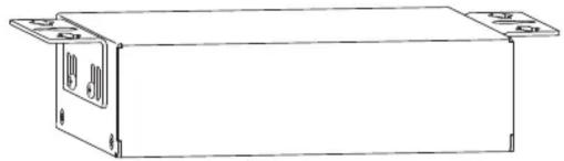
The Surface Mount Kit is designed for mounting a single module (to the wall, on or under a desk, etc.) The kit contains brackets and screws. The brackets may be attached to mount the top or the bottom flush with the mounting surface.
Important: Be careful not to block vent holes on the module when mounting.
natural_image
Line drawing of a rectangular electronic device with mounting flanges and internal ports (no text or symbols)
natural_image
Line drawing of a rectangular electronic device with mounting feet (no text or symbols)
natural_image
Technical line drawing of a rectangular electronic component with mounting flanges (no text or symbols)
natural_image
Line drawing of a rectangular electronic enclosure with mounting flanges (no text or symbols)FIG. 3 Attach brackets in either top or bottom position (various size modules shown)
The following instructions can be used for attaching brackets when surface mounting or for pole mounting.
Tip: Laying the module and brackets on a flat surface when you attach the brackets helps align them.
To attach brackets to a module:
- Insert the #4-40 3/16 inch pan head screws (provided) per FIG. 4 and tighten. Brackets can either align flush with the top or with the bottom.

natural_image
Technical line drawing of a rectangular electronic enclosure with two side panels and mounting connectors (no text or symbols)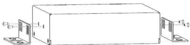
natural_image
Technical line drawing of a rectangular electronic enclosure with mounting brackets and side connectors (no text or symbols)FIG. 4 Insert screws and tighten
Mounting on Surface
Note: The #8 x 1/2 inch tapping pan head screws provided for mounting to a flat surface are designed for wood. If the module needs to be mounted on a different type of surface, use the appropriate type of fastener, e.g., dry wall anchors (not provided).
To mount a module with brackets to a flat surface:
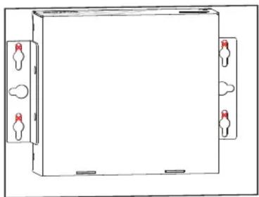
- Place the module in the desired final position on the mounting surface and mark the screw position as indicated in FIG. 5.
natural_image
Simple line drawing of a rectangular enclosure with four hanging light bulbs on both sides (no text or symbols)FIG. 5 Mark screw positions
Important: The mark for the screw's position in each of the mounting holes needs to be made in the end of the slots (all marks to either the top of the slots or all marks to the bottom).
- Set the module aside. If using the wood screws provided, drill pilot holes (drill size 29; hole diameter 0.136 in.) for the screws 1/2 inch (1.27 cm) deep. Start the screws in the holes. Do not tighten completely.

natural_image
Empty white rectangle with four small red square markers at corners (no text or symbols)FIG. 6 Drill pilot holes and start screws, but do not tighten
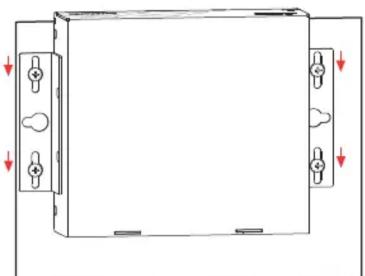
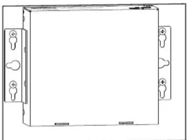
- Align the module with the center of the double key-hole slots over the screws and slide into place as indicated in FIG. 7.
natural_image
Pure technical diagram of a rectangular enclosure with mounting holes and directional arrows, no text or symbols present.FIG. 7 Align module over screws and slide into place
- Tighten the screws.
natural_image
Simple line drawing of a rectangular electronic device with mounting holes and connectors (no text or symbols)FIG. 8 Tighten screws
Pole Mount (FG1010-723)
The Pole Mount Kit is designed for mounting a single module to a projector pipe (or other 2 inch diameter pipes). The kit contains all the mounting hardware for the assembly in FIG. 9.
To mount a module using brackets and bolts:
- Attach the mounting brackets to the module according to the instructions for surface mounting (see FIG. 4).
- Insert the first u-bolt around the pole/pipe and through the bracket and plate according to FIG. 9.
- Fasten securely with the hex nuts.
- Repeat Steps 2 and 3 using the remaining u-bolt, bracket, plate, and hex nuts.

natural_image
Technical line drawing of two vertical cylindrical mechanical components with mounting brackets and connecting rods (no text or symbols)FIG. 9 Mount to projector pipe with bolts through brackets
Brand : AMX
Model : AVB-VSTYLE-POLE-MNT
Category : Professional audiovisual equipment