
PreMax - Audio Equipment Radial Engineering - Free user manual and instructions
Find the device manual for free PreMax Radial Engineering in PDF.


| Product Type | Microphone Preamp with 3-Band Equalizer (500 Series Module) |
| Dimensions | 5.25 x 1.5 x 6.6 in (133 x 38 x 168 mm) |
| Weight | 1.5 lb (0.7 kg) |
| Power Requirement | 56 mA (from 500 series rack) |
| Preamp Type | Accustate gain control with variable gain front end |
| Frequency Response | 20 Hz – 20 kHz (-1.5 dB @ 20 Hz) |
| Total Harmonic Distortion | < 0.003% |
| Dynamic Range | 112 dB |
| Input Impedance | 3.3 kΩ (XLR mic input) |
| Maximum Input Level | +24 dBu |
| Gain (Mic to Line Out) | 52 dB |
| Gain (Omniport Instrument) | 30 dB |
| Maximum Output Level | +26 dBu |
| Output Impedance | 300 Ω |
| Equivalent Input Noise | -120 dBu |
| Noise Floor | -85 dB @ +40 dB gain |
| Intermodulation Distortion | 0.006% |
| LED Indicators | Signal (green), Overload (red) |
| Equalizer | 3-band: Low & High shelving (±12 dB), Mid peaking (±12 dB), bypass switch |
| High-Pass Filter | 100 Hz, 12 dB/octave |
| Phantom Power | +48V (recessed switch with LED indicator) |
| Polarity Reverse | 180° switch |
| Omniport Input | 1/4" high-Z instrument input (requires Radial Workhorse or compatible rack) |
| Input/Output Connectors | XLR (mic input & line output), 1/4" TRS (Omniport) |
| Warranty | 3 years, transferable |
Frequently Asked Questions - PreMax Radial Engineering
User questions about PreMax Radial Engineering
0 question about this device. Answer the ones you know or ask your own.
Ask a new question about this device
Download the instructions for your Audio Equipment in PDF format for free! Find your manual PreMax - Radial Engineering and take your electronic device back in hand. On this page are published all the documents necessary for the use of your device. PreMax by Radial Engineering.
USER MANUAL PreMax Radial Engineering
*▲□ ◆✿✿

WARNING NOTICE TO USER!
Although preventative safety measures have been designed into Radial 500 series products we strictly advise against hot-swapping modules or plugging and unplugging them when the Workhorse or other 500 series racks are powered on. Hot swapping can cause connection sparks at the card-edge connector that could send damaging transients to other equipment. This also reduces the life span of the contacts. Damage due to hot swapping is not covered under warranty. There are no user serviceable parts inside.
TM
X◇\*□□▲☆□○□■÷\*
Table of Contents Page
Overview....1
Features 3
Making Connections....4
Getting Started ....5
3 Band EQ....6
Ominiport....7
Specifications 8
Block Diagram....8
Radial Limited Warranty ....Back Cover
INTRODUCTION
Thank you for purchasing the Radial PreMax, a combination microphone preamp and equalizer designed to fit the more advanced Radial 500 series power racks and earlier designs made by others. We invested a ton of effort during the development stage to make the PreMax quick to set up and easy to use so that you can enjoy superb results each and every time you put it to work. Plug in your favorite microphone, set the Accustate gain control for maximum signal-to-noise and use the powerful three band EQ to shape your sound!
There are lots of little extras that are built into these fabulous devices. This is where reading the manual is essential. Please take a few minutes to read through so you can take full advantage of the feature set and maximize the performance.
If afterwards you have a question that is not covered herein, please take a minute to consult the PreMax's FAQ section on the Radial website. This is where we post questions and answers from users along with updates. If you still have a question, feel free to send us an email at info@radialeng.com and we will do our best to answer in short order.
Now get ready to record with ease and confidence!
OVERVIEW
The PreMax is a combination preamp and three band equalizer jammed into a single wide 500 series module. By housing both processors together we can optimize the signal path, maximum performance and minimize fuss. This accelerates setup times and eliminates many of the challenges that make getting an instrument to sound right.

flowchart
graph LR
    A["MIC"] --> C["MIC PREAMP"]
    B["INSTRUMENT"] --> C
    C --> D["3-BAND EQUALIZER"]
    D --> E["LINE OUTPUT"]
The Preamp
The design begins with a state-of-the-art microphone preamp coupled with Radial's unique Accustate gain control. Unlike traditional preamps that only achieve their optimal signal-to-noise when pushed to maximum, Accustate employs a dual wafer potentiometer that simultaneously sets the input sensitivity and preamp gain so that the signal-to-noise ratio remains constant at all levels. This is particularly important when recording in the digital domain where even the slightest bit of noise can be audible.

Traditional preamp gain Accustate preamp gain
The preamp is equipped with +48V phantom power for condenser microphones and active direct boxes, a 180° polarity reverse to help phase align two mics when recording in stereo and a handy high-pass filter that eliminates low frequency rumble to help clean up your tracks. Visual monitoring is provided by two LEDs that display signal and peak output levels.

flowchart
graph LR
    A["MIC INPUT"] --> B["+48 VOLTS"]
    C["OMNIPORT"] --> D["180° REV"]
    B --> E["MIC PREAMP"]
    D --> F["ACCUSTATE GAIN"]
    E --> G["HI-PASS FILTER"]
    F --> G
    G --> H["HIGH SHELVING"]
    H --> I["MID PEAKING"]
    I --> J["LOW SHELVING"]
    J --> K["LINE OUTPUT"]
    K --> L["LED METER"]
    style E fill:#f9f,stroke:#333
    style F fill:#f9f,stroke:#333
    style G fill:#f9f,stroke:#333
    style H fill:#f9f,stroke:#333
    style I fill:#f9f,stroke:#333
    style J fill:#f9f,stroke:#333
    style K fill:#f9f,stroke:#333
    style L fill:#f9f,stroke:#333
When using the PreMax in a Radial 500 series power rack the Omniport is available and functions as a high-impedance 14 input for electronic instruments. For more information please refer to the Omniport description later in this user guide.
The Equalizer
After the preamp has amplified the mic signal it feeds a traditional 3 band EQ for tone shaping. This great sounding EQ lets you gently boost the top end for more clarity, add warmth to the bottom end, or cut back the mids on an overly aggressive instrument. A front panel switch lets you bypass the EQ to compare the pre-post effect.
We chose to employ a traditional old-school 3 band EQ to perform the task. This type of EQ is super fast to use, sounds musical and is not as cumbersome as a parametric. We carefully selected the EQ frequencies to sound musical and work with today's production styles.

The high frequency control makes it simple to add extra sparkle to a 12-string acoustic guitar or reduce the shrillness of a violin. The low frequency control can boost the bottom end of a male voice or be used to fatten a bass guitar. Cutting some mid-range can pull a track back into the mix, while boosting mid-range brings it forward.
This straight forward equalizer makes it easy to get great sounds up in your monitors quickly. A handy EQ-IN bypass switch lets you compare the sound of the track between the pre and post EQ settings.
FEATURE SET
-
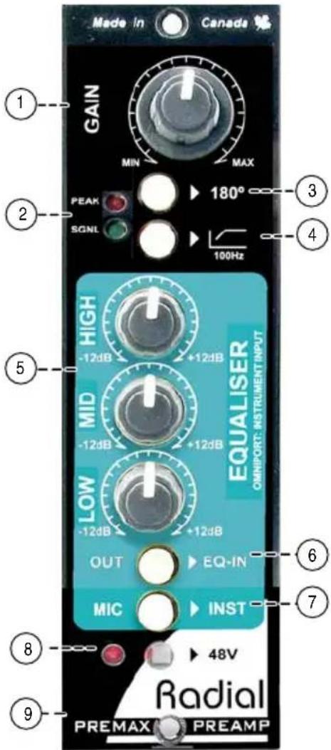
GAIN: Used to set the gain of the mic preamp. Accustate gain control sets the input sensitivity and gain at the same time to optimize signal to noise at all settings.
-
LED METERING: Signal and peak LED meter provide visual feedback of signal status and max output level.
-
180° REVERSE: Inverts the polarity to help phase align two microphones when recording in stereo.
-
HIGH-PASS FILTER: Gently rolls-off low frequencies below 100Hz to reduce rumble which can muddy up a recording.
-
3-BAND EQ: Low, mid and high frequency controls with +/-12dB of boost or cut are used for tone shaping.
-
EQ IN/OUT: Bypass control lets you compare the tone of the original signal without the EQ and the tone created when the EQ is inserted.
-
MIC/INST: Toggles the input from the balanced XLR on the rear of the power rack to the Omniport 14 ” instrument input on your Radial power rack.
-
48V PHANTOM: Power for condenser microphones. Switch is recessed to prevent accidental use that could damage vintage ribbon microphones or cause loud pops. The LED indicator illuminates when the phantom power is active.
-
OMNIPORT: Rear mounted 1/4" connector designated as an instrument input to allow guitar and bass to be recorded direct. Available when used with the Radial Workhorse.
MAKING CONNECTIONS
As with all audio equipment, always ensure levels are turned down and equipment is turned off before making any connections or inserting the PreMax into a 500 series power rack. This common practice ensures turn-on transients will not damage more sensitive components such as tweeters.
Slide your PreMax module into the 500 series power rack until the card-edge on the board is firmly seated into the slot connector on the main board. Care should be taken when inserting the module to maintain correct alignment of the card-edge with the connector. After inserting the PreMax into your 500 series rack, secure it using the supplied machine screws to ensure it does not accidentally become dislodged during use. To prevent damage to the power rack, do not over-tighten the mounting screws.
Most 500 series racks are equipped with balanced XLR connectors. When you insert the PreMax into your 500 series rack it will automatically route the rear panel XLR connections to the module's input and output. This is augmented with 14 TRS connectors if using the PreMax in a Radial Workhorse 500 series power rack. The PreMax follows the AES standard with pin-2 (+) hot, pin-3 (-) cold. Most devices are wired this way but older vintage equipment should be checked to confirm compatibility with AES standards.
Connect a microphone or direct box to the PreMax input using a standard XLR patch cable. If you are using a condenser microphone or active direct box, turn on the 48V phantom power. The switch is recessed to prevent accidental turn on. Use a small screw driver or paper clip to push in the switch. A red LED will illuminate when phantom power is active.

Rear panel mic input and line output. Radial Workhorse 500 rack.
Connect the line-level output of the PreMax to your audio system so that you can audition the PreMax. We recommend that you first listen to the PreMax on its own before combining with effects or other signal processors until you have had a chance to familiarize yourself with the preamp and equalizer functions. Using your own voice to test is best, as it gives you a familiar starting place.
USING THE PREAMP
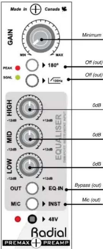
Once you have the PreMax safely mounted in your rack and patched into your recording system, set the controls on the front panel as shown here on the right. All four buttons should be set to their outward position. This 'start position' bypasses the equalizer from the signal chain to enable you to first set the preamp to optimize signal-to-noise.
Power on the audio system and turn up the volume on your monitors. Plug in your mic and slowly turn up the preamp gain control while observing the LED meter. The bottom green LED illuminates when the output level is above -40dB and indicates the PreMax is working. The top red peak LED illuminates when the signal is near clipping. If it flashes on peaks, turn the preamp gain down by about 10% to ensure a strong signal level without clipping. Always test at a low volume to ensure the PreMax is patched in and working. If you do not hear any sound, check that your 500 series rack is patched correctly. If you are using a condenser microphone, ensure the 48V phantom power is turned on by checking the red LED at the bottom of the front panel.
Using The 180° Polarity Reverse
When recording an instrument you may want to use two microphones and two PreMax preamps at the same time to capture the sound. Together, the mics can create a timbre that a single mic cannot. One may be positioned near the instrument while the second may be set further away to capture the room's natural ambiance. Engaging the 180^ polarity reverse on one PreMax can sometimes achieve a fuller sound by aligning the low frequency phase response of the two mics. (Devices like the Radial Phazer take this to another level by allowing you to adjust the phase incrementally.)
STARTING POSITION
The 180° polarity reverse can also be used to correct the phase of older vintage equipment that may have been made before the AES standard was established. Most equipment today employs the standard with pin-1 ground, pin-2 hot (+), and pin-3 cold (-). Depressing the 180° polarity reverse switch will toggle pins 2 and 3 at the XLR input to compensate for non-standard or vintage equipment.
Using The High Pass Filter
A high-pass filter (low cut) is generally used in the studio to clean up excessive bottom end that can render recordings muddy and cause some instruments to become indistinct. Bass frequencies are so much longer and more powerful than highs, so controlling them can often be very beneficial. Live sound engineers will often reduce the low end from acoustic instruments to reduce resonance and prevent run-away feedback.

line
| Time (k) | Value | | -------- | ----- | | 20 | -20 | | 50 | -10 | | 100 | -5 | | 200 | -2 | | 500 | -1 | | 1x30 | -1 | | 5x100 | -1 |High-pass filter response
USING THE EQUALIZER
Once you have the preamplifier working, activate the equalizer using the EQ-IN switch and begin testing the three EQ bands. Each of the three bands uses an active EQ control capable of cutting, or boosting the amplitude within the band's frequency range. The center, 12 o'clock position, is the neutral point or 0dB. Rotating the control clockwise from center will boost frequencies. Turning it counter clockwise from center cuts them.
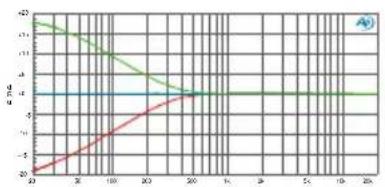
Start your experimentation with the high and low shelving filters set at the 12 o'clock position. These filters affect the treble and bass frequencies and offer 12dB of cut or boost. These 'shelving' fi Iters gradually increase amplitude from a fi xed frequency to the limit of the audio spectrum.

line
| Time (s) | Series 1 (%) | Series 2 (%) | Series 3 (%) | |---|---|---|---| | 0 | -20 | -4 | -2 | | 2 | -15 | -4 | -2 | | 4 | -10 | -4 | -2 | | 6 | -5 | -4 | -2 | | 8 | 0 | -4 | -2 | | 10 | 5 | -4 | -2 | | 12 | 10 | -4 | -2 | | 14 | 15 | -4 | -2 | | 16 | 20 | -4 | -2 | | 18 | 25 | -4 | -2 | | 20 | 30 | -4 | -2 | The chart displays a single data series with two distinct lines: one in green and one in red, both plotted against a grid background. The x-axis is labeled 'Time (s)' and the y-axis is labeled 'a (%). The values for the green line are explicitly labeled as 'A').
line
| X-Axis | Series 1 (Green) | Series 2 (Red) | Series 3 (Blue) | |---|---|---|---| | 0 | -1 | -1 | -1 | | 10 | -0.5 | -1.0 | -1 | | 20 | 0.0 | -1.5 | -1 | | 30 | 0.5 | -2.0 | -1 | | 40 | 1.0 | -2.5 | -1 | | 50 | 1.5 | -3.0 | -1 | | 60 | 2.0 | -3.5 | -1 | | 70 | 2.5 | -4.0 | -1 | | 80 | 3.0 | -4.5 | -1 | | 90 | 3.5 | -5.0 | -1 | | 100 | 4.0 | -5.5 | -1 | | 110 | 4.5 | -6.0 | -1 | | 120 | 5.0 | -6.5 | -1 | | 130 | 5.5 | -7.0 | -1 | | 140 | 6.0 | -7.5 | -1 | | 150 | 6.5 | -8.0 | -1 | | 160 | 7.0 | -8.5 | -1 | | 170 | 7.5 | -9.0 | -1 | | 180 | 8.0 | -9.5 | -1 | | 190 | 8.5 | -10.0 | -1 | | 200 | 9.0 | -10.5 | -1 | | 210 | 9.5 | -11.0 | -1 | | 220 | 10.0 | -11.5 | -1 | | 230 | 10.5 | -12.0 | -1 | | 240 | 11.0 | -12.5 | -1 | | 250 | 11.5 | -13.0 | -1 | | 260 | 12.0 | -13.5 | -1 | | 270 | 12.5 | -14.0 | -1 | | 280 | 13.0 | -14.5 | -1 | | 290 | 13.5 | -15.0 | -1 | | 300 | 14.0 | -15.5 | -1 | | 310 | 14.5 | -16.0 | -1 | | 320 | 15.0 | -16.5 | -1 | | 330 | 15.5 | -17.0 | -1 | | 340 | 16.0 | -17.5 | -1 | | 350 | 16.5 | -18.0 | -1 | | 360 | 17.0 | -18.5 | -1 | | 370 | 17.5 | -19.0 | -1 | | 380 | 18.0 | -19.5 | -1 | | 390 | 18.5 | -20.0 | -1 | | 400 | 19.0 | -20.5 | -1 | | 410 | 19.5 | -21.0 | -1 | | 420 | 20.0 | -21.5 | -1 | | 430 | 20.5 | -22.0 | -1 | | 440 | 21.0 | -22.5 | -1 | | 450 | 21.5 | -23.0 | -1 | | 460 | 22.0 | -23.5 | -1 | | 470 | 22.5 | -24.0 | -1 | | 480 | 23.0 | -24.5 | -1 | | 490 | 23.5 | -25.0 | -1 | | 500 | 24.0 | -25.5 | -1 | | 510 | 24.5 | -26.0 | -1 | | 520 | 25.0 | -26.5 | -1 | | 530 | 25.5 | -27.0 | -1 | | 540 | 26.0 | -27.5 | -1 | | 550 | 26.5 | -28.0 | -1 | | 560 | 27.0 | -28.5 | -1 | | 570 | 27.5 | -29.0 | -1 | | 580 | 28.0 | -29.5 | -1 | | 590 | 28.5 | -30.0 | -1 | | 600 | 29.0 | -30.5 | -1 | | 610 | 29.5 | -31.0 | -1 | | 620 | 30.0 | -31.5 | -1 | | 630 | 30.5 | -32.0 | -1 | | 640 | 31.0 | -32.5 | -1 | | 650 | 31.5 | -33.0 | -1 | | 660 | 32.0 | -33.5 | -1 | | 670 | 32.5 | -34.0 | -1 | | 680 | 33.0 | -34.5 | -1 | | 690 | 33.5 | -35.0 | -1 | | 700 | 34.0 | -35.5 | -1 | | 710 | 34.5 | -36.0 | -1 | | 720 | 35.0 | -36.5 | -1 | | 730 | 35.5 | -37.0 | -1 | | 740 | 36.0 | -37.5 | -1 | | 750 | 36.5 | -38.0 | -1 | | 760 | 37.0 | -38.5 | -1 | | 770 | 37.5 | -39.0 | -1 | | 780 | 38.0 | -39.5 | -1 | | 790 | 38.5 | -40.0 | -1 | | 800 | 39.0 | -40.5 | -1 | | 810 | 39.5 | -41.0 | -1 | | 820 | 40.0 | -41.5 | -1 | | 830 | 40.5 | -42.0 | -1 | | 840 | 41.0 | -42.5 | -1 | | 850 | 41.5 | -43.0 | -1 | | 860 | 42.0 | -43.5 | -1 | | 870 | 42.5 | -44.0 | -1 | | 880 | 43.0 | -44.5 | -1 | | 890 | 43.5 | -45.0 | -1 | | 900-949: The chart is a single horizontal line representing the average value of the 'Average' series for each series of 'Series' (Series A). The 'Series B' series represents the 'Series C' series of 'Series D'. The 'Series E' series represents the 'Series F' series of 'Series G'. The 'Series H' series represents the 'Series I' series of 'Series J'. The 'Series K' series represents the 'Series L' series of 'Series M'. The chart is divided into four sections by dividing the lines into sections labeled 'A', 'B', and 'C'.
Low frequency EQ Mid-range frequency EQ High frequency EQ
The mid-range is a constant-Q filter that forms a bell-shaped curve centered around the middle of the audio spectrum. As the amount of boost or cut is increased, a wider band of frequencies are affected and the mid-range begins to overlap and interact with the high and low bands.
You can take advantage of the interaction between bands to produce an EQ curve that a single filter can not achieve on it's own. For instance, boosting the mid-range while cutting high band can produce a complex frequency response that accentuates the high-mids but rolls-off the hiss. Likewise, cutting the bass and boosting the mids will accentuate low-mid frequencies while also cutting out low frequency rumble. Taking this further, you can employ the high-pass filter in the preamp section to cut deep bass.

line
| x | e B d (Green) | e B d (Red) | | ---- | ------------- | ----------- | | 20 | 0 | 0 | | 50 | ~0 | ~0 | | 100 | ~0 | ~0 | | 200 | ~-5 | ~-5 | | 500 | ~-10 | ~-10 | | 1k | ~-10 | ~-15 | | 2k | ~-10 | ~-10 | | 5k | ~-5 | ~-5 | | 10k | ~0 | ~0 | | 20k | 0 | 0 |The mid-range is superimposed over the high and low filters to show the frequency overlap between bands.
Omniport™ instrument input
If you are inserting the PreMax into Radial 500 series power rack, you can use the Omniport as a high impedance instrument input to record electric guitar, bass or keyboards. Simply connect to the PreMax via the Omniport jack using a standard 14 instrument cable. Set the MIC/INST switch on the front panel to the inward position to activate the Omniport. Adjust the preamp gain and equalizer tone to suit and record as normal.

Omniport input on Radial 500 series racks.

The MIC/INST selects between the XLR mic input and the Omniport instrument input.
RADIAL PREMAX 500 SPECIFICATIONS
Preamp circuit type: ....Accustate input with variable gain front end.
Compressor circuit type: ......Feed forward VCA compressor with true RMS sidechain.
Frequency response: 20Hz \~ 20kHz (-1.5dB @ 20Hz)
Total harmonic distortion: ....<0.003%
Dynamic range: 112dB
Input impedance: 3.3kOhms
Maximum input: ....+24dBu
Gain- mic in to line out: 52dB
Gain - Omniport inst in: 30dB
Maximum output: ....+26dBu
Output impedance: 300 Ohms
Equivalent input noise: ....-120dBu
Noise floor: ....-85dB @ +40dB of gain
Intermodulation distortion: 0.006%
LED meter: ......Signal (green), over load (red)
Omniport function: ......High-Z instrument input
EQ filter slope: 12 db/Octave
Power requirement: 56mA
XLR configuration:....Follows AES spec: pin-1 ground, pin-2 (+), pin-3 (-)
Size: 5.25" x 1.5" x 6.6" (13.34 x 3.81 x 16.75cm) Standard 500 series rack format
Weight: 1.5lbs (0.7Kg)
Warranty: 3 Years, transferable
BLOCK DIAGRAM
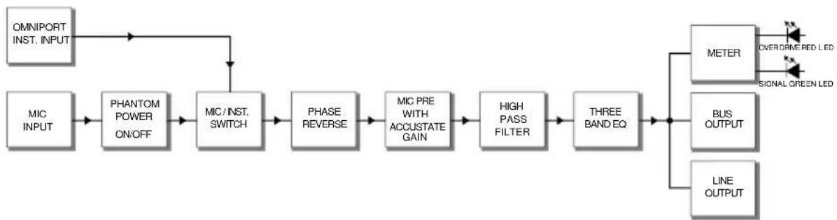
flowchart
graph LR
    A["OMNIPORT INST. INPUT"] --> B["MIC INPUT"]
    B --> C["PHANTOM POWER ON/OFF"]
    C --> D["MIC/INST. SWITCH"]
    D --> E["PHASE REVERSE"]
    E --> F["MIC PRE WITH ACCUSTATE GAIN"]
    F --> G["HIGH PASS FILTER"]
    G --> H["THREE BANDEQ"]
    H --> I["METER"]
    I --> J["BUS OUTPUT"]
    I --> K["LINE OUTPUT"]
    J --> L["OVERDRIVE RED LED"]
    J --> M["SIGNAL GREEN LED"]
THREE YEAR TRANSFERABLE LIMITED WARRANTY
RADIAL ENGINEERING LTD. ("Radial") warrants this product to be free from defects in material and workmanship and will remedy any such defects free of charge according to the terms of this warranty. Radial will repair or replace (at its option) any defective component(s) of this product (excluding finish and wear and tear on components under normal use) for a period of three (3) years from the original date of purchase. In the event that a particular product is no longer available, Radial reserves the right to replace the product with a similar product of equal or greater value. In the unlikely event that a defect is uncovered, please call 604-942-1001 or email service@radialeng.com to obtain an RA number (Return Authorization number) before the 3 year warranty period expires. The product must be returned prepaid in the original shipping container (or equivalent) to Radial or to an authorized Radial repair center and you must assume the risk of loss or damage. A copy of the original invoice showing date of purchase and the dealer name must accompany any request for work to be performed under this limited and transferable warranty. This warranty shall not apply if the product has been damaged due to abuse, misuse, misapplication, accident or as a result of service or modification by any other than an authorized Radial repair center.
THERE ARE NO EXPRESSED WARRANTIES OTHER THAN THOSE ON THE FACE HEREOF AND DESCRIBED ABOVE. NO WARRANTIES WHETHER EXPRESSED OR IMPLIED, INCLUDING BUT NOT LIMITED TO, ANY IMPLIED WARRANTIES OF MERCHANTABILITY OR FITNESS FOR A PARTICULAR PURPOSE SHALL EXTEND BEYOND THE RESPECTIVE WARRANTY PERIOD DESCRIBED ABOVE OF THREE YEARS. RADIAL SHALL NOT BE RESPONSIBLE OR LIABLE FOR ANY SPECIAL, INCIDENTAL OR CONSEQUENTIAL DAMAGES OR LOSS ARISING FROM THE USE OF THIS PRODUCT. THIS WARRANTY GIVES YOU SPECIFIC LEGAL RIGHTS, AND YOU MAY ALSO HAVE OTHER RIGHTS, WHICH MAY VARY DEPENDING ON WHERE YOU LIVE AND WHERE THE PRODUCT WAS PURCHASED.

This product is intended for professional use only. The user should be familiar and experienced with the 500 series rack and module format.

Radial Engineering Ltd. 1588 Kebet Way, Port Coquitlam BC V3C 5M5 tel: 604-942-1001 • fax: 604-942-1010 info@radialeng.com • www.radialeng.com


- WARNING NOTICE TO USER!
- TM
- X◇\*□□▲☆□○□■÷\*
- Table of Contents Page
- INTRODUCTION
- OVERVIEW
- The Preamp
- The Equalizer
- FEATURE SET
- MAKING CONNECTIONS
- USING THE PREAMP
- Using The 180° Polarity Reverse
- Using The High Pass Filter
- USING THE EQUALIZER
- Omniport™ instrument input
- RADIAL PREMAX 500 SPECIFICATIONS
- BLOCK DIAGRAM
- THREE YEAR TRANSFERABLE LIMITED WARRANTY
Brand : Radial Engineering
Model : PreMax
Category : Audio Equipment