
LX1300.7 - Receiver KICKER - Free user manual and instructions
Find the device manual for free LX1300.7 KICKER in PDF.


| Product Type | Car Audio Amplifier |
| Model | LX1300.7 |
| Brand | KICKER |
| Number of Channels | 7 |
| RMS Power (per channel at 4 ohms) | 50W x 6 + 200W x 1 |
| Peak Power | 1300W |
| Frequency Response | 20Hz - 20kHz |
| Input Sensitivity | 200mV - 4V |
| Signal-to-Noise Ratio | > 100dB |
| Total Harmonic Distortion | < 0.05% |
| Dimensions (W x L x H) | 17.0 x 10.0 x 2.0 inches |
| Weight | 6.5 lbs |
| Power Supply Voltage | 10-16V DC |
| Fuse Rating | 40A (x2) |
| Features | Variable crossover (HPF/LPF), bass boost, remote subwoofer level control, speaker-level inputs, preamp outputs |
| Mounting Type | Hardware not included; mount in dry, ventilated location |
| Maintenance | Clean with dry cloth; avoid liquids; ensure air vents are clear |
| Safety | Disconnect battery before installation; use proper gauge wire; professional installation recommended |
| Repairability | No user-serviceable parts; contact authorized service center |
| Compliance | CE, RoHS |
Frequently Asked Questions - LX1300.7 KICKER
User questions about LX1300.7 KICKER
0 question about this device. Answer the ones you know or ask your own.
Ask a new question about this device
Download the instructions for your Receiver in PDF format for free! Find your manual LX1300.7 - KICKER and take your electronic device back in hand. On this page are published all the documents necessary for the use of your device. LX1300.7 by KICKER.
USER MANUAL LX1300.7 KICKER
IMPORTANT: KICKER recommends a professional installation performed by authorized retailers. You are solely responsible for safely mounting and wiring your products.
Scan here for owner's manual Escanee aquí para manual del Propietario Scannen Sie hier nach benutzerhandbuch Scannez ici pour manuel d'utilisation

CAUTION: KICKER PRODUCTS CAN PRODUCE SOUND LEVELS THAT CAN PERMANENTLY DAMAGE YOUR HEARING! TURNING UP A SYSTEM TO A LEVEL THAT HAS AUDIBLE DISTORTION IS MORE DAMAGING TO YOUR EARS THAN LISTENING TO AN UNDISTORTED SYSTEM AT THE SAME VOLUME LEVEL. THE THRESHOLD OF PAIN IS ALWAYS AN INDICATOR THE SOUND LEVEL IS TOO LOUD AND MAY PERMANENTLY DAMAGE YOUR HEARING. PLEASE USE COMMON SENSE WHEN CONTROLLING VOLUME.
OUR GOODS COME WITH GUARANTEES THAT CANNOT BE EXCLUDED UNDER THE AUSTRALIAN CONSUMER LAW. YOU ARE ENTITLED TO A REPLACEMENT OR REFUND FOR A MAJOR FAILURE AND FOR COMPENSATION FOR ANY OTHER REASONABLY FORESEEABLE LOSS OR DAMAGE. YOU ARE ALSO ENTITLED TO HAVE THE GOODS REPAIRED OR REPLACED IF THE GOODS FAIL TO BE OF ACCEPTABLE QUALITY AND THE FAILURE DOES NOT AMOUNT TO A MAJOR FAILURE.
See owner's manual for information on installation, and how to use amplifier features such as LED settings, gain, crossover, LXCC, and more!
IMPORTANT SAFETY WARNING
PROLONGED CONTINUOUS OPERATION OF AN AMPLIFIER, SPEAKER, OR SUBWOOFER IN A DISTORTED, CLIPPED OR OVER-POWERED MANNER CAN CAUSE YOUR AUDIO SYSTEM TO OVERHEAT, POSSIBLY CATCHING FIRE AND RESULTING IN SERIOUS DAMAGE TO YOUR COMPONENTS AND/OR VEHICLE. AMPLIFIERS REQUIRE UP TO 4 INCHES (10CM) OPEN VENTILATION. SUBWOOFERS SHOULD BE MOUNTED WITH AT LEAST 1 INCH (2.5CM) CLEARANCE BETWEEN THE FRONT OF THE SPEAKER AND ANY SURFACE. KICKER PRODUCTS ARE CAPABLE OF PRODUCING SOUND LEVELS THAT CAN PERMANENTLY DAMAGE YOUR HEARING! TURNING UP A SYSTEM TO A LEVEL THAT HAS AUDIBLE DISTORTION IS MORE DAMAGING TO YOUR EARS THAN LISTENING TO AN UNDISTORTED SYSTEM AT THE SAME VOLUME LEVEL. THE THRESHOLD OF PAIN IS ALWAYS AN INDICATOR THAT THE SOUND LEVEL IS TOO LOUD AND MAY PERMANENTLY DAMAGE YOUR HEARING. PLEASE USE COMMON SENSE WHEN CONTROLLING VOLUME.
The LX Amps are the successor to KICKER's legendary IQ & KX amplifiers, designed to outperform and manufactured with the highest quality materials, these amps are the pinnacle of audio performance. With the preamp controls moved to the outboard LXCC controller they are the perfect power stage to be used with a standalone DSP. The LXCC also gives you precise control over advanced options like Crossover Type, Slope, Left Channel Time Delay, Channel Summing & Parametric Bass Boost. They also feature ultra efficient high-power Class-D output stages, fully-customizable RGB LED accent lighting with color and intensity control, full-differential inputs. The included LXRC Remote Bass control (mono, 5-ch & 7-ch amps, only) allows for extended features like amp voltage monitoring, sub volume control, output clip indication and SHOCwave2.0. Use with any combination of KICKER products, including KICKER subwoofers and full-range speakers.
LX Mono
Specifications
Model: LX850.1 LX1250.1
Dynamic Power [Watts] 1100W 1600W
RMS Power Output [Watts]
@ 14.4V, 4Ω mono, ≤ 1% THD+N 300W X 1 400W X 1
@ 14.4V, 2Ω mono, < 1% THD+N 500W X 1 750W X 1
@ 14.4V, 1Ω mono, ≤ 1% THD+N 850W X 1 1250W X 1
Length [in, cm] 9 7/16, 24 9 7/16, 24
Specifications Common to All Models
Frequency Response [Hz] 10Hz–160Hz
Selectable Electronic Crossover Variable LP 40Hz-160Hz
Parametric Bass Boost Yes, 0 - +6dB, Variable Center 20Hz-80 Hz
Variable Bandwidth 1–5
Variable Subsonic Filter Variable Hi-Pass 10Hz–80Hz
Remote Bass Control Yes (Included)
Height [in, cm] 2 3/8, 6
Width [in, cm] 87/16, 21
Signal-to-Noise Ratio [dB] >95dB, a-weighted, re: rated power
Signal-to-Noise Ratio [dB] >75dB (ref: 1W output)
Input Sensitivity Low Level: 125mV–5V
High Level: 1V–40V
Model: LX1650.1 LX3000.1
Dynamic Power [Watts] 2200W 3800W
RMS Power Output [Watts]
@ 14.4V, 4Ω mono, ≤ 1% THD+N 550W X 1 1100W X 1
@ 14.4V, 2Ω mono, ≤ 1% THD+N 1000W X 1 2000W X 1
@ 14.4V, 10 mono, ≤ 1% THD+N 1650W X 1 3000W X 1
Length [in, cm] 9 7/16, 24 12 5/8, 32
Specifications Common to All Models
Frequency Response [Hz] 10Hz–160Hz
Selectable Electronic Crossover Variable LP 40Hz-160 Hz
Parametric Bass Boost Yes, 0–+6dB, Variable Center 20Hz–80 Hz
Variable Bandwidth 1–5
Variable Subsonic Filter Variable Hi-Pass 10Hz–80Hz
Remote Bass Control Yes (Included)
Height [in, cm] 2 3/8, 6
Width [in, cm] 8 7/16, 21
Signal-to-Noise Ratio [dB] >95dB, a-weighted, re: rated power
Signal-to-Noise Ratio [dB] >75dB (ref: 1W output)
Input Sensitivity Low Level: 125mV–5V
High Level: 1V–40V
Note: All specifications and performance figures are subject to change. Please visit www.kicker.com for the most current information. To get the best performance from your new KICKER amplifier, we recommend using genuine KICKER speakers, accessories and wiring.
Mounting
Choose a structurally sound location to mount your KICKER amplifier. Make sure there are no items behind the area where the screws will be driven. Choose a location that allows at least 4" (10cm) of open ventilation for the amplifier. Drill four holes using a 7/64" (3mm) bit and use the supplied #8 screws to mount the amplifier.
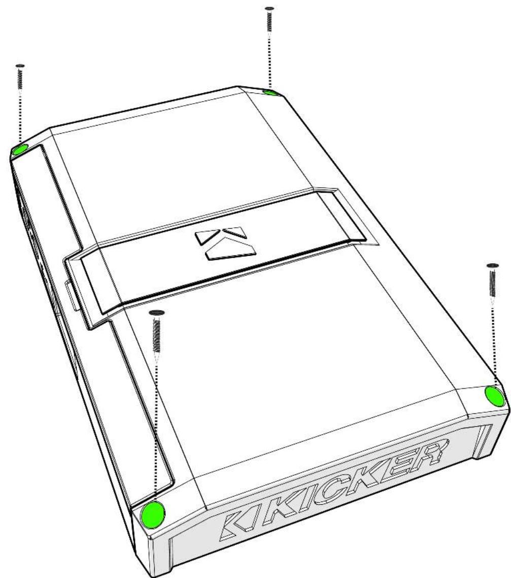
Remove and orient the magnetized KICKER plate and badge as needed.
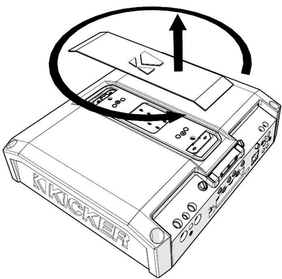
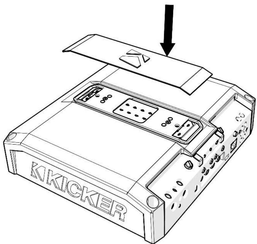
Remove the magnetized top panel cover to access the LX amplifier's power distribution and speaker output terminals, as well as gain and LED accent lighting settings.
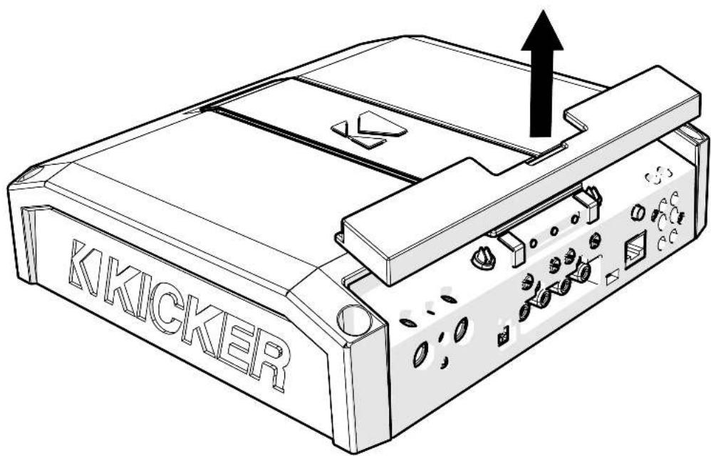
Power Wiring
Click Here for Amplifier Install Kits
Model External Fuse (sold separately) Power/Ground Wire KICKER Wiring Kit
| LX850.1 | 1 x 80 Ampere | 4 Gauge | PK4, CK4 |
| LX1250.1 | 1 x 100 Ampere | 1/0 Gauge | PKD1 |
| LX1650.1 | 1 x 150 Ampere | 1/0 Gauge | PKD1 |
| LX3000.1 | 1 x 200 Ampere | 1/0 Gauge | PKD1 |
KICKER will provide a three-year warranty with all LX-Series Amplifier purchases paired with a qualifying KICKER Installation Kit*.
This extends the standard warranty by an additional year. Amplifier and Kit must be purchased from an Authorized KICKER Dealer.
Using poor-quality, under-spec wiring kits will impede LX amplifier performance.
A superior-quality KICKER installation Kit is guaranteed to extend the life of LX amplifiers.
The new extended warranty applies only to KICKER amplifiers and accessories sold to consumers by Authorized KICKER Doaors in the United States of America or its possessions. It also only applies to the original purchaser of KICKER amplifiers and accessories. One warranty extension per amplifier is allowed regardless of the number of amplifier installation kits purchased. This program does not apply to "B"-stock product or lactory-returbished product.
This offer is for a limited time, so see your local Authorized KICKER Dealer soon for details.
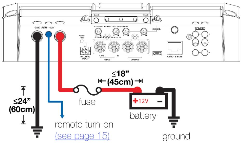
Disconnect the vehicle's battery to avoid an electrical short. A good ground connection is important. Make the ground wire short, 24" (60cm) or less and, if not conneted to the battery, connect it to a paint-and-corrosion-free, solid metal area of the vehicle's chassis. Adding an additional ground wire of this same gauge (or larger) between the battery's negative post and the vehicle chassis is recommended. Keep the audio signal cable away from factory wiring harnesses and other power wiring. If you need to cross this wiring, cross it at a 90 degree angle.
Fuse installation should be as close as possible to the battery, and no further than 18" (45cm) of the battery, and in-line with the power cable, which is connected to your LX Amplifier. Make sure the power wire is routed so that it will not be damaged, crimped, or shorted. If you ever need to remove the amplifier from the vehicle after it has been installed, the ground wire should be the last wire disconnected from the amplifier; just the opposite as when you installed it.
Pro Tip: All that's left are KICKER Subwoofers, and a few cables, and you'll have an audio upgrade that will dominate any factory system! KICKER amplifiers make it easy to upgrade to solid bass with your existing or stock source unit. Ask your dealer about KICKER upgrades.
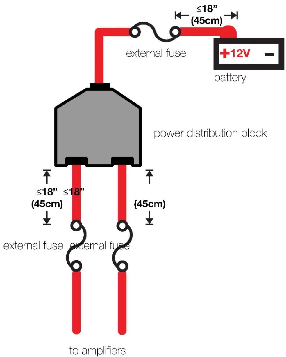
For multiple amplifier installations where distribution blocks are used, each amplifier should have its proper-rated fuse, or breaker, installed between the amplifier and the distribution block within eighteen inches of the block, or on the distribution block if it provides for fusing. The primary power wire should also be fused between the battery and distribution block, within eighteen inches of the battery's positive terminal, with a fuse or breaker rated at least to the sum of the individual amplifier's fuse values, but doesn't exceed the capacity of your wiring.
Input Wiring
The LX-series are capable of receiving both Low-level signals with the RCA inputs and Hi-level signals with the Hi-Level Input wiring harness on the front panel of the amplifier.
The LX Mono amplifiers also feature RCA Output to conveniently chain more LX amplifiers in your audio system.
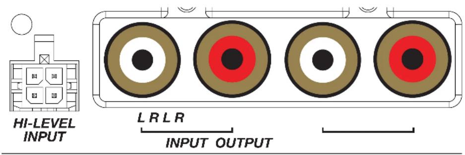
The input channel corresponding to the wiring harness colors are:
Left: White, White/Black
Right: Grey, Grey/Black
Subwoofer Wiring
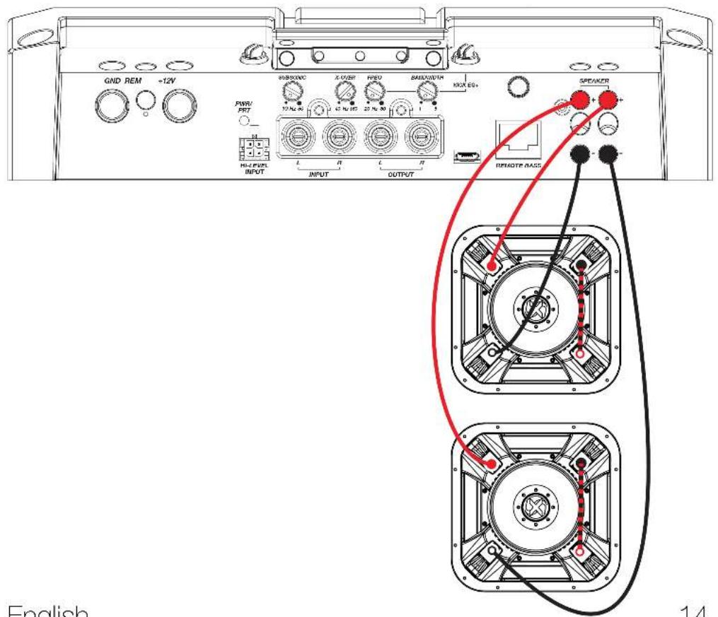
Single 2Ω Dual Voice Coil L7X Subwoofer wired in parallel.
Final impedance of load must be a minimum of 1 .
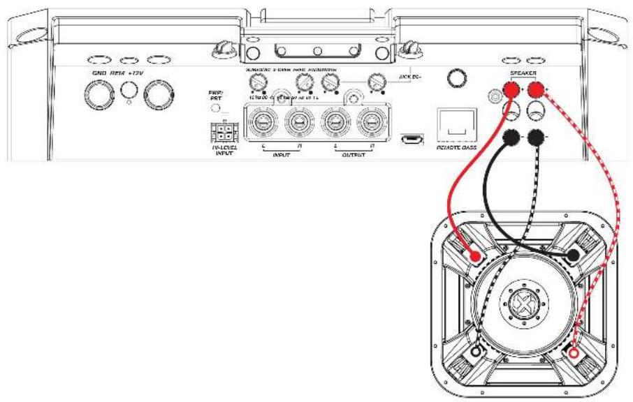
Two 1Ω Dual Voice Coil L7X Subwoofers wired in Series/Parallel
Final impedance of load must be a minimum of 1
Operation
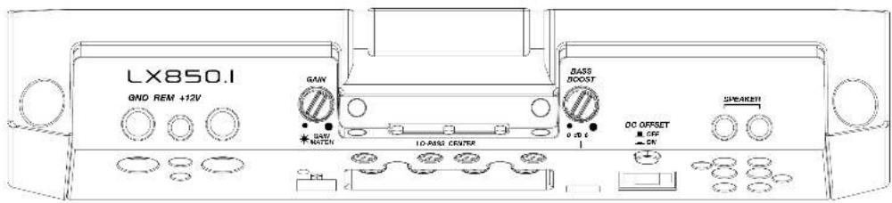
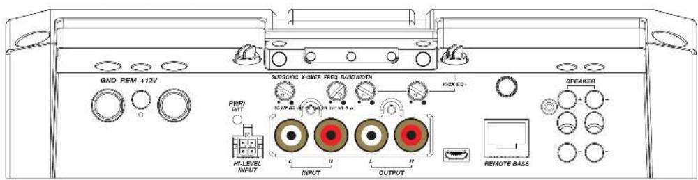
Automatic Turn-On: The LX-series offers two different automatic turn-on modes; +12V and DC Offset.
- Remote Turn-On: Run 18 gauge wire from the Remote Turn-On Lead on your source unit to the REM terminal on the LX amplifier's end panel.
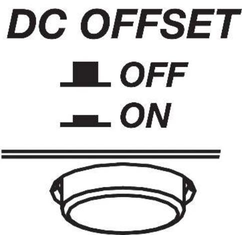
- DC Offset Turn-On: The DC Offset mode uses the Hi-Level input harness to detect >2.5V DC from the Hi-Level speaker output of the source unit when it has been turned on. To use DC offset mode, the DC OFF/ON push button must be in the ON or IN position. When using DC Offset mode, the REM terminal becomes a switched +12V output (100mA) to turn other amplifiers and devices on.
INPUT GAIN: The input gain control is not a volume control. It matches the output of the source unit to the input level of the amplifier. Maximum power out of the amplifier is possible with the gain in the lowest position. Incorrectly setting the gain can result in distorted output or damage to, and premature failure of, your speakers.
LX850.1
GND REM +12V
natural_image
Three identical concentric circles with no text or symbols, arranged horizontally (no text or symbols present)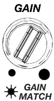
GAIN MATCHING: In any audio system, the goal is to reach maximum input and output levels without distortion or clipping. The engineers at KICKER have taken the guesswork, and hassle, out of matching the output voltage of your source unit to the amplifier with the Gain Matching feature. To begin, you'll need to download the KICKER test tones from KICKER.com.
These test tones are sine waves meant to provide a consistent signal for the amplifier to reference. The different recording levels are designed to give you the perfect gain match for your application.
OdBFS: Designed for audiophile applications to give you distortion free audio output with the most dynamic range.
-5dBFS: Designed for normal/daily applications, there will be less dynamic range but higher potential audio output levels. With this set up you can get some occasional clipping from the amplifier.
-10dBFS: Designed only for Subwoofer applications, there will be less dynamic range but higher potential audio output levels. With this set up you can get some clipping from the amplifier.
Afterwards, use the following procedure to accurately Gain Match your amplifier(s):
- Disconnect the speakers from the amplifier.
- Set all EQ and crossover settings to flat on your source unit.
- Play the downloadable file from KICKER.com
- Turn the source unit up to the maximum unclipped volume level. If you cannot accurately determine this, 34 volume is a good starting point.
- Increase the gain of the amplifier until the Gain LED turns on.
- Decrease the gain of the amplifier until the Gain LED turns off.
To use the preferred method of setting the input gain using a voltmeter or oscilloscope, begin by turning off the amplifier and disconnecting all speakers from it. Turn the gain knob completely off (counterclockwise) and all crossovers off, or to their least effective setting. If a remote bass accessory is connected to the amplifier, turn it completely on (clockwise). Ensure all EQ and DSP settings on the source unit such as bass, treble, fader, seating position etc are set to linear, flat, center, or off. Turn on the amplifier. With an oscilloscope, probe the signal coming from the source unit and play a 0dB sine wave through your source unit and increase the volume until you see the waveform clip slightly. Turn the head unit down one notch as this is the maximum unclipped volume level of your source unit. Sine wave tracks can be downloaded for free from KICKER.com under the "Support" tab. Use the 50Hz sine wave to set the gain for a subwoofer and the 1kHz sine wave for full-range speakers. Set your voltmeter or oscilloscope to measure AC voltage. Place the voltmeter's probes on the amplifier's speaker output terminals. With the sine wave playing, slowly turn the gain knob clockwise and watch the AC voltage on the voltmeter increase.
When the desired voltage is shown (reference power chart at KICKER.com), or you start to see the waveform square off stop increasing the gain, turn the amplifier off, reconnect all speakers and set the crossovers to your desired setting. Your gain is now set for maximum unclipped power from the amplifier. If you increase amplitude using settings on the source unit or the bass boost on the amplifier it will introduce distortion and you will need to redo these steps.
LED Accent Lighting: Remove the top panel cover to access the LED Accent Lighting Controls. These also control the LXRC lighting.

Change LED Change LED
Color Brightness

Press the Change LED Color button to cycle through the available colors. Press the Change LED Brightness to change the intensity of the light, or to turn it off. Available Colors:
Red Magenta Violet
Blue Light Blue Cyan
Dark Green Green Yellow
Orange White
Factory Reset: Remove the top panel cover to access the Factory Reset button. To restore factory settings, press and hold the Factory Reset button for 10 seconds. Turn the amplifier off and back on by cycling the ignition.

Factory Reset - Press & Hold for 10 seconds
WARNING: Factory reset will reset all settings that are controlled by LXCC to factory (including crossover)
KICK EQ Parametric Bass Boost:
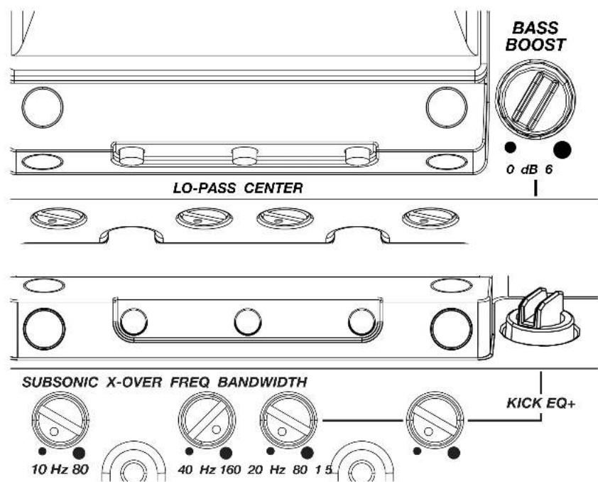
The BASS BOOST may be set from 0dB–6dB. Use the FREQ setting to adjust the center frequency from 20Hz–80Hz. Use the BANDWIDTH setting to set the bandwidth (Q) of the center frequency, from 1–5.
LO-PASS FREQ (Crossover Control):
The variable lo-pass crossover on the side of the amplifier allows you to adjust the lo-pass crossover frequency from 40Hz–160Hz (Linkwitz-Riley, 24dB/octave).
SUBSONIC (Subsonic Filter): Use the Subsonic filter to engage a hi-pass crossover from 10Hz–80Hz with a 24db/octave Linkwitz-Riley slope. This is used to protect the subwoofer driver from over-excursion due to ultra-low frequencies, preventing damage while ensuring your amplifier's power is used efficiently.
LXRC Installation
The LXRC is a multi-function remote bass knob that further expands the DSP features of the LX amplifier, with access to LED lighting changes, real-time battery input voltage monitoring, clip output indication, and KICKER's proprietary SHOCwave 2.0 (Sub-Harmonic Octave Creation) algorithm.
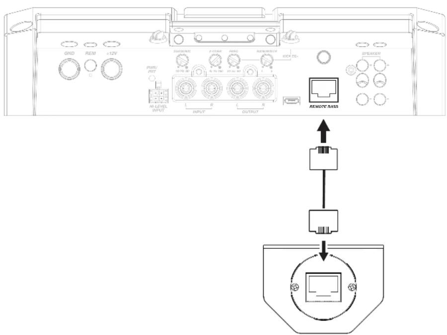
Connect the supplied RJ-45 cable from the back of the LXRC to the Remote Bass jack of the LX amplifier.
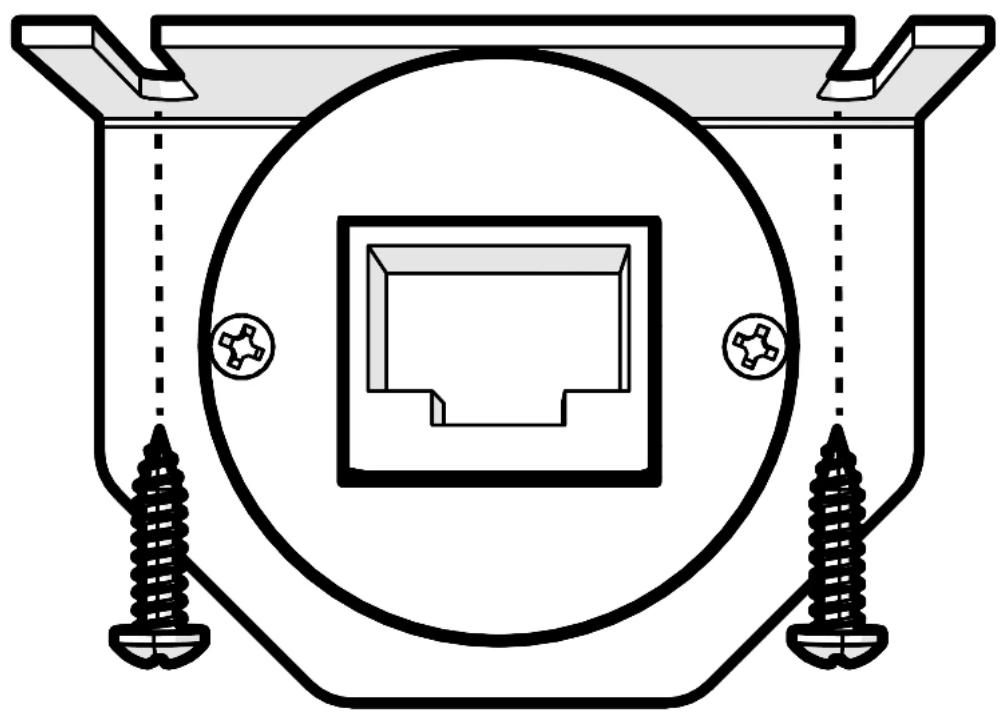
Surface Mounting: To surface mount the LXRC, place the LXRC against a surface and secure the mounting bracket using the supplied screws.
natural_image
Pure technical diagram of a mechanical component with screw fasteners and a central square housing (no text or symbols)Flush Mounting: To flush mount the LXRC behind a mounting surface, begin by cutting a 1-inch diameter hole in the mounting surface, being careful not to drill through existing wiring or mechanisms.
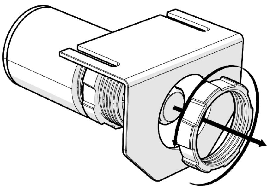
Remove the LXRC front mounting nut and mounting bracket.
natural_image
Technical line drawing of a mechanical component with internal threading and housing (no text or symbols)Adjust the rear mounting nut forward to set the protrusion of the LXRC knob.
natural_image
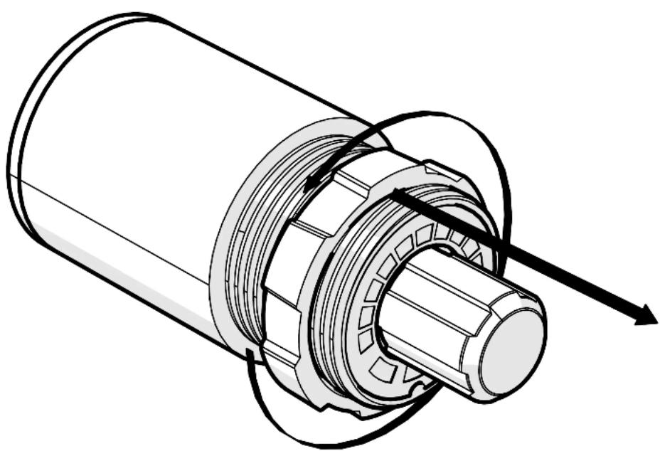
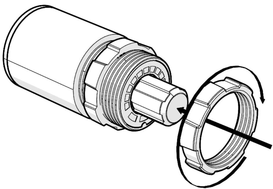
Technical illustration of a mechanical assembly with internal gears and a directional arrow (no text or symbols)Place the LXRC through the mounting hole, then reattach the front mounting nut to secure the remote against the mounting surface.
natural_image
Technical illustration of a mechanical assembly showing a cylindrical component being inserted into a bearing housing with rotating shafts (no text or symbols)Connect the LXRC to the Remote Bass jack of the LX amplifier.
LXRC Operation
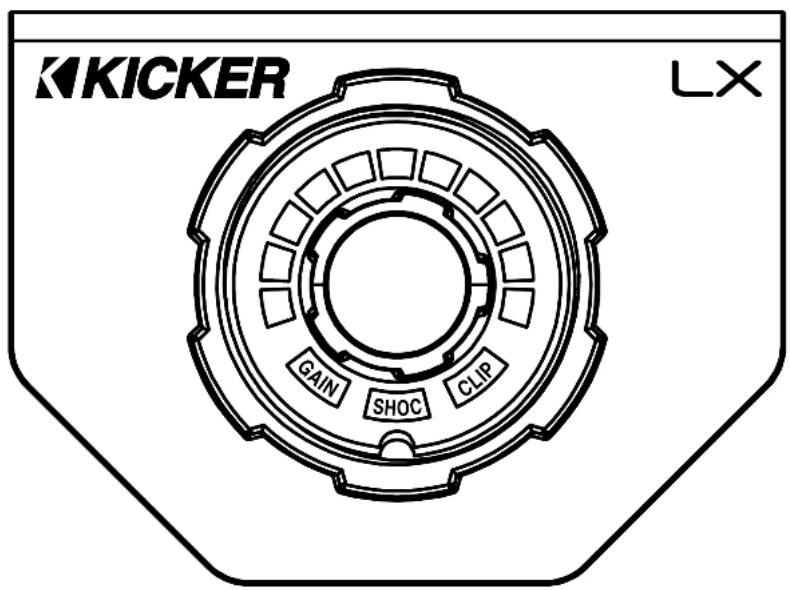
The LXRC serves as both a rotary knob for precise adjustments and as a multi-function push-button to change modes, with an illuminated LED ring to display the current setting. You may cycle through most modes by pressing and holding the button for <3 seconds (short-press). Once adjustments have been made, wait for the LXRC to save the settings and return to the default Voltage Indication mode.
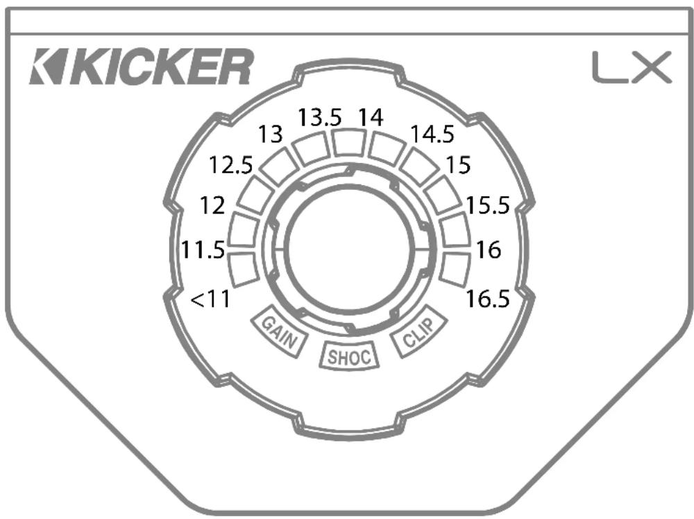
Voltage: The LXRC will default to showing the input voltage, with the remote knob LED ring serving as a VU meter for 11V–16V. To enter Input Voltage Indication mode, perform a short-press until the menu cycles, perform no interaction for 5 seconds.
radar
| Measurement | Value | | ----------- | ----- | | GAIN | 16.5 | | SHOC | 15.5 | | CLIP | 16 | | <11 | 11.5 | | 12 | 12 | | 13 | 12.5 | | 13.5 | 13 | | 14 | 14 | | 14.5 | 15 | | 15 | 16 |Gain (Remote Level): The LXRC gain control is a gain attenuator from -26dB to 0dB. This will allow you to conveniently adjust the gain of the subwoofer channel on the fly, with the maximum being the gain setting you've selected on the LX amplifier top panel. To enter Remote Level mode, turn the knob while in Voltage mode, or short-press the knob until the menu reaches Gain.
SHOCwave™ 2.0: The SHOCwave (Sub Harmonic Octave Creation) will restore low frequencies that are weaker in older recordings or lost in data compression. The SUBWOOFER channel must be operating with a full-range signal for this effect to work properly. Short-Press & hold the knob until SHOC is illuminated, then adjust the knob to a level that is satisfactory.
Brightness: Enter the Brightness adjustment mode by pressing and holding the LXRC button for >3 seconds (long-press). Rotate the knob to adjust the brightness to a satisfactory level, then perform no action for 5 seconds and the LXRC will return to default voltage mode. While in voltage mode, if you double-press the remote button the LXRC LED array will turn on/off.
Clip: The CLIP display serves as a global clip indicator to show when a clipped output signal is detected. If you change your Gain or SHOCwave setting, you may notice the CLIP LED become active. This means your new DSP settings have caused an output to clip and you should reduce the gain or compensate in some other way.
Troubleshooting
If your amplifier does not appear to be working, check the obvious things first such as blown fuses, poor or incorrect wiring connections, incorrect setting of crossover switch and gain controls, etc. There are Power (PWR) & Protection (PRT) LEDs on the side panel of your KICKER LX series amplifier. Depending on the state of the amplifier and the vehicle's charging system, the LEDs will glow either green or red. When the green LED is lit, this indicates the amplifier is turned on and no trouble exists.
Green LED off, no output? With a Volt Ohm Meter (VOM) check the following: ①+12 volt power terminal (should road +12V to +16V) ②Remote turn-on terminal (should road +12V to +16V) ③Check for reversed power and ground connections ④Ground terminal, for proper conductivity.
Green LED on, no output? Check the following: ① RCA connections ② Test speaker outputs with a "known" good speaker. ③ Substitute source unit with a "known" good source unit. ④ Check for a signal in the RCA cable feeding the amplifier with the VOM meter set to measure "AC" voltage. Use a 50Hz test tone.
Red (PRT) LED flickering with loud music? The red (PRT) LED indicates low battery voltage. Check all the connections in your vehicle's charging system. It may be necessary to replace or charge your vehicle's battery or replace your vehicle's alternator.
Red (PRT) LED on, no output? ①Amplifier is very hot = thermal protection is engaged. Test for proper impedance at the speaker terminals with a VOM meter set to "DC Resistance" (see the diagrams in this manual for minimum recommended impedance and multiple speaker wiring suggestions). Also check for adequate airflow around the amplifier. ②Amplifier shuts down only while vehicle is running = voltage protection circuitry is engaged. Voltage to the amplifier is not within the 6–16 volt operating range. Have the vehicle's charging and electrical system inspected. ③Amplifier will only play at low volume levels = short circuit protection is engaged. Check for speaker wires shorted to each other or to the vehicle chassis. Check for damaged speakers or speaker(s) operating below the minimum recommended impedance.
No or low output? ① Check the balance and fader controls on source unit. ② Check the RCA (or speaker input) and speaker output connections. ③ Check the volume level on your source unit, to include the volume level of any connected phones or MP3 players.
Alternator noise-whining sound with engine's RPM? ① Check for damaged RCA (or speaker input) cable ② Check the routing of RCA (or speaker input) cable ③ Check the source unit for proper grounding ④ Check the gain settings and turn them down if they are set too high.
CAUTION: When jump starting the vehicle, be sure that connections made with jumper cables are correct. Improper connections can result in blown amplifier fuses as well as the failure of other critical systems in the vehicle.
If you have more questions about the installation or operation of your new KICKER product, see the Authorized KICKER Dealer where you made your purchase. For more advice on installation, click on the SUPPORT tab on the KICKER homepage, www.KICKER.com. Choose the TECHNICAL SUPPORT tab, choose the subject you are interested in, and then download or view the corresponding information. Please E-mail support@KICKER.com or call Technical Services (405) 624-8583 for unanswered or specific questions.
LX Stereo
Specifications
Model: LX500.4
| Dynamic Power [Watts] 1100W | |
| RMS Power Output [Watts] | |
| @ 14.4V, 4Ω stereo, < 1% THD+N | 125W X 4 AMP1, AMP2 |
| @ 14.4V, 20 stereo, ≤ 1% THD+N | 225W X 4 AMP1, AMP2 |
| @ 14.4V, 40 mono, ≤ 1% THD+N | 450W X 2 |
| Frequency Response [Hz] 20Hz-20KHz | |
| Selectable Electronic Crossover Selectable Crossover Slopes: | |
| 12dB and 24dB (Linkwitz-Riley);12, 18 and 24dB (Butlerworth) | |
| AMP1, AMP2 Off/HP/LP/BP(LX Control Center HP 20Hz-5KHz, LP 40Hz-5KHz) | |
| Fader On/Off Switch Yes | |
| Remote Bass Control No (Incompatible) | |
| Length [in, cm] 9 7/16, 24 | |
| Height [in, cm] 2 3/8, 6 | |
| Width [in, cm] 8 7/16, 21 | |
| Signal-to-Noise Ratio [dB] | >95dB, a-weighted, re: rated power |
| Signal-to-Noise Ratio [dB] | >75dB (ref: 1W output) |
| Input Sensitivity Low Level: 125mV-5V | |
| High Level: 1V-40V | |
Note: All specifications and performance figures are subject to change. Please visit www.kicker.com for the most current information. To get the best performance from your new KICKER amplifier, we recommend using genuine KICKER speakers, accessories and wiring.
Mounting
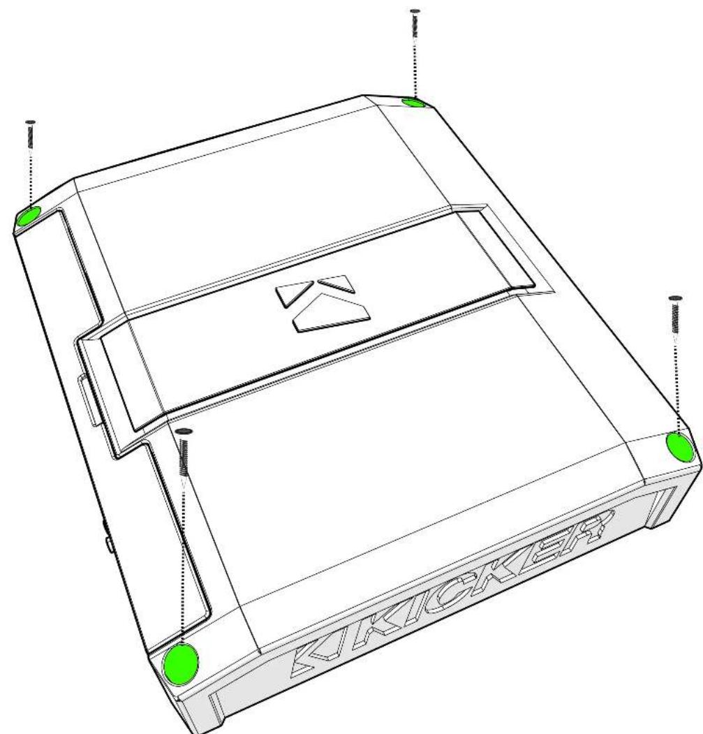
Choose a structurally sound location to mount your KICKER amplifier. Make sure there are no items behind the area where the screws will be driven. Choose a location that allows at least 4" (10cm) of open ventilation for the amplifier. Drill four holes using a 7/64" (3mm) bit and use the supplied #8 screws to mount the amplifier.
natural_image
Technical line drawing of a device casing with green circular markers and dotted lines indicating mounting points (no text or symbols present)Remove and orient the magnetized KICKER plate and badge as needed.
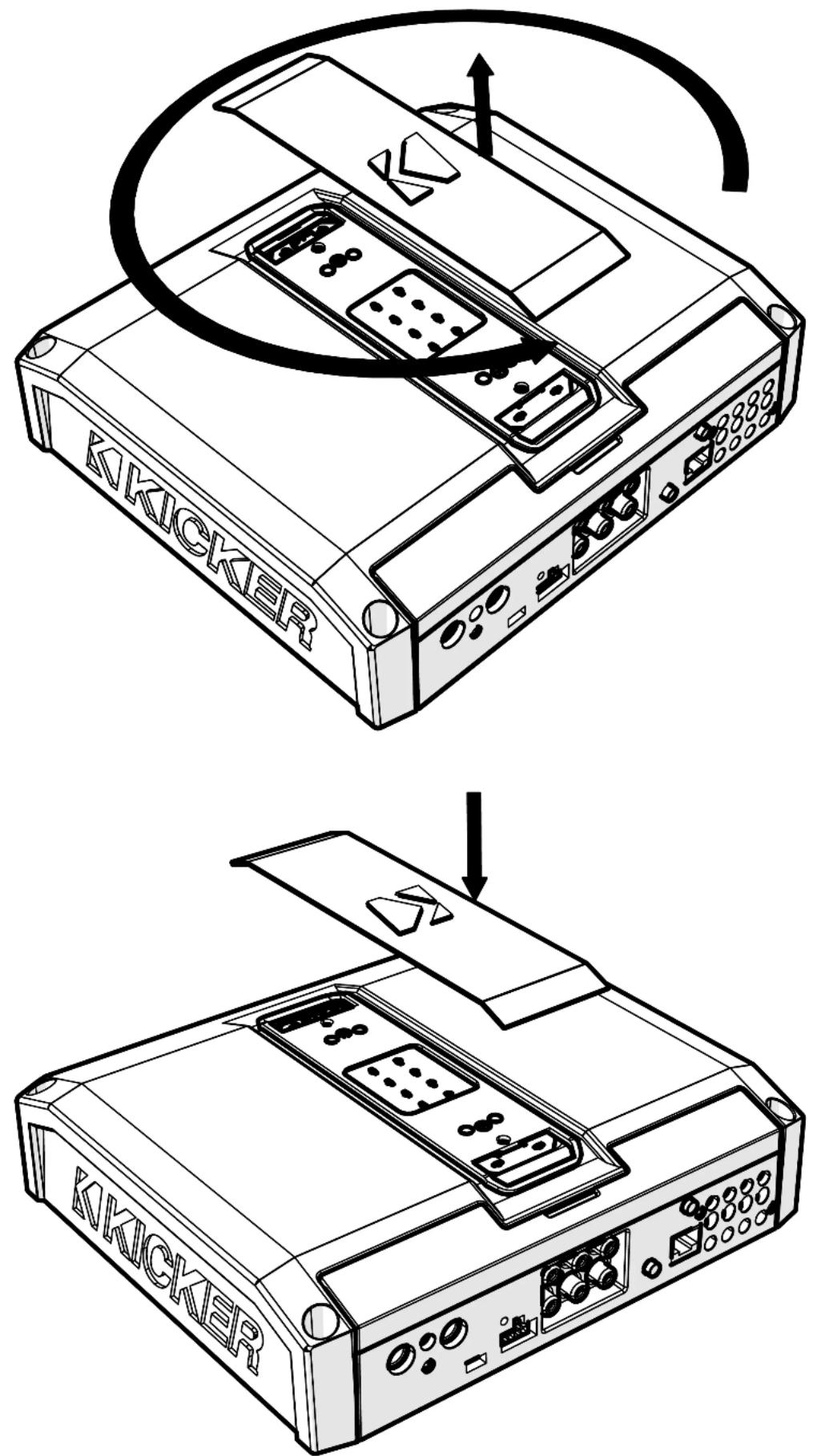
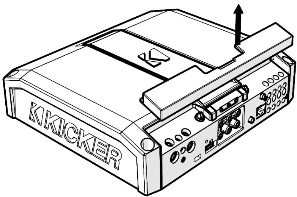
Remove the magnetized top panel cover to access the LX amplifier's power distribution and speaker output terminals, as well as gain and LED accent lighting settings.
Power Wiring
Click Here for Amplifier Install Kits
Model
External Fuse (sold separately)
Power/Ground Wire
KICKER Wiring Kit
LX500.4 1 x 80 Ampere 4 Gauge PK4, CK4
KICKER will provide a three-year warranty with all LX-Series Amplifier purchases paired with a qualifying KICKER Installation Kit*.
This extends the standard warranty by an additional year. Amplifier and Kit must be purchased from an Authorized KICKER Dealer.

Using poor-quality, under-spec wiring kits will impede LX amplifier performance.
A superior-quality KICKER installation Kit is guaranteed to extend the life of LX amplifiers.
The new extended warranty applies only to KICKER amplifiers and accessories sold to consumers by Authorized KICKER Dealers in the United States of America or its possessions. It also only applies to the original purchaser of KICKER amplifiers and accessories. One warranty extension per amplifier is allowed regardless of the number of amplifier installation kits purchased. This program does not apply to "B"-stock product or lactory-returbished product.
This offer is for a limited time, so see your local Authorized KICKER Dealer soon for details.
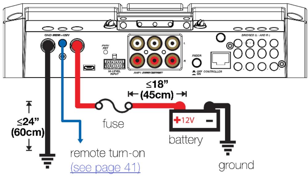
Disconnect the vehicle's battery to avoid an electrical short. A good ground connection is important. Make the ground wire short, 24" (60cm) or less and, if not conneted to the battery, connect it to a paint-and-corrosion-free, solid metal area of the vehicle's chassis. Adding an additional ground wire of this same gauge (or larger) between the battery's negative post and the vehicle chassis is recommended. Keep the audio signal cable away from factory wiring harnesses and other power wiring. If you need to cross this wiring, cross it at a 90 degree angle.
Fuse installation should be as close as possible to the battery, and no further than 18" (45cm) of the battery, and in-line with the power cable, which is connected to your LX Amplifier. Make sure the power wire is routed so that it will not be damaged, crimped, or shorted. If you ever need to remove the amplifier from the vehicle after it has been installed, the ground wire should be the last wire disconnected from the amplifier; just the opposite as when you installed it.
Pro Tip: All that's left are KS speakers, and a few cables, and you'll have an audio upgrade that will dominate any factory system! KICKER amplifiers make it easy to upgrade to solid bass with your existing or stock source unit. Ask your dealer about KICKER upgrades.
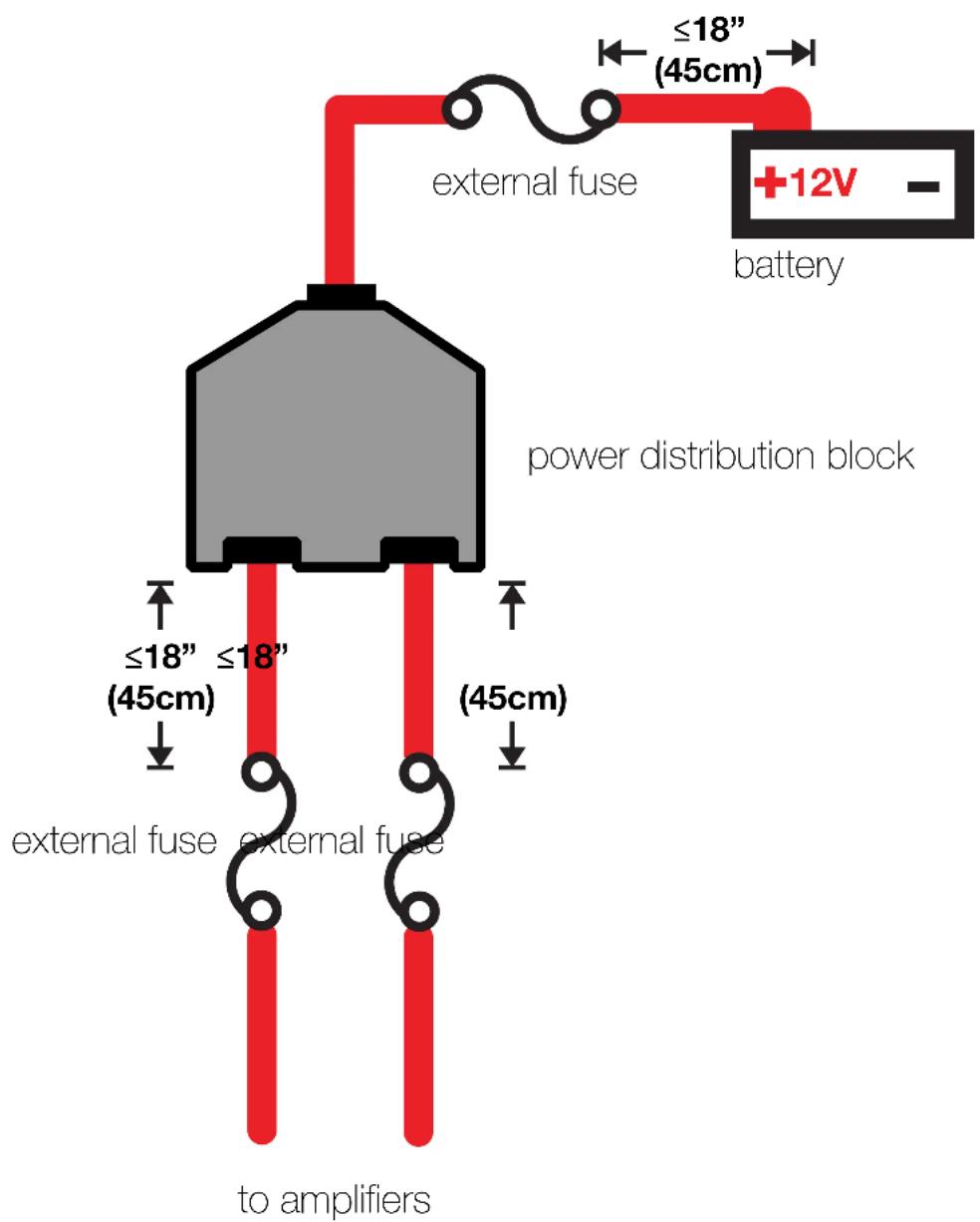
For multiple amplifier installations where distribution blocks are used, each amplifier should have its proper-rated fuse, or breaker, installed between the amplifier and the distribution block within eighteen inches of the block, or on the distribution block if it provides for fusing. The primary power wire should also be fused between the battery and distribution block, within eighteen inches of the battery's positive terminal, with a fuse or breaker rated at least to the sum of the individual amplifier's fuse values, but doesn't exceed the capacity of your wiring.
Input Wiring
The LX-series are capable of receiving both Low-level signals with the RCA inputs and Hi-level signals with the Hi-Level Input wiring harness on the front panel of the amplifier.
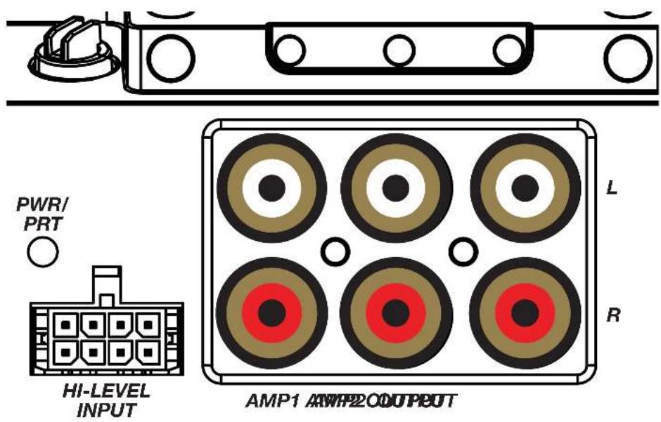
The input channel corresponding to the wiring harness colors are:
AMP1 Left: White, White/Black AMP1 Right: Grey, Grey/Black AMP2 Left: Green, Green/Black AMP2 Right: Purple, Purple Black
Speaker Wiring
Stereo Operation
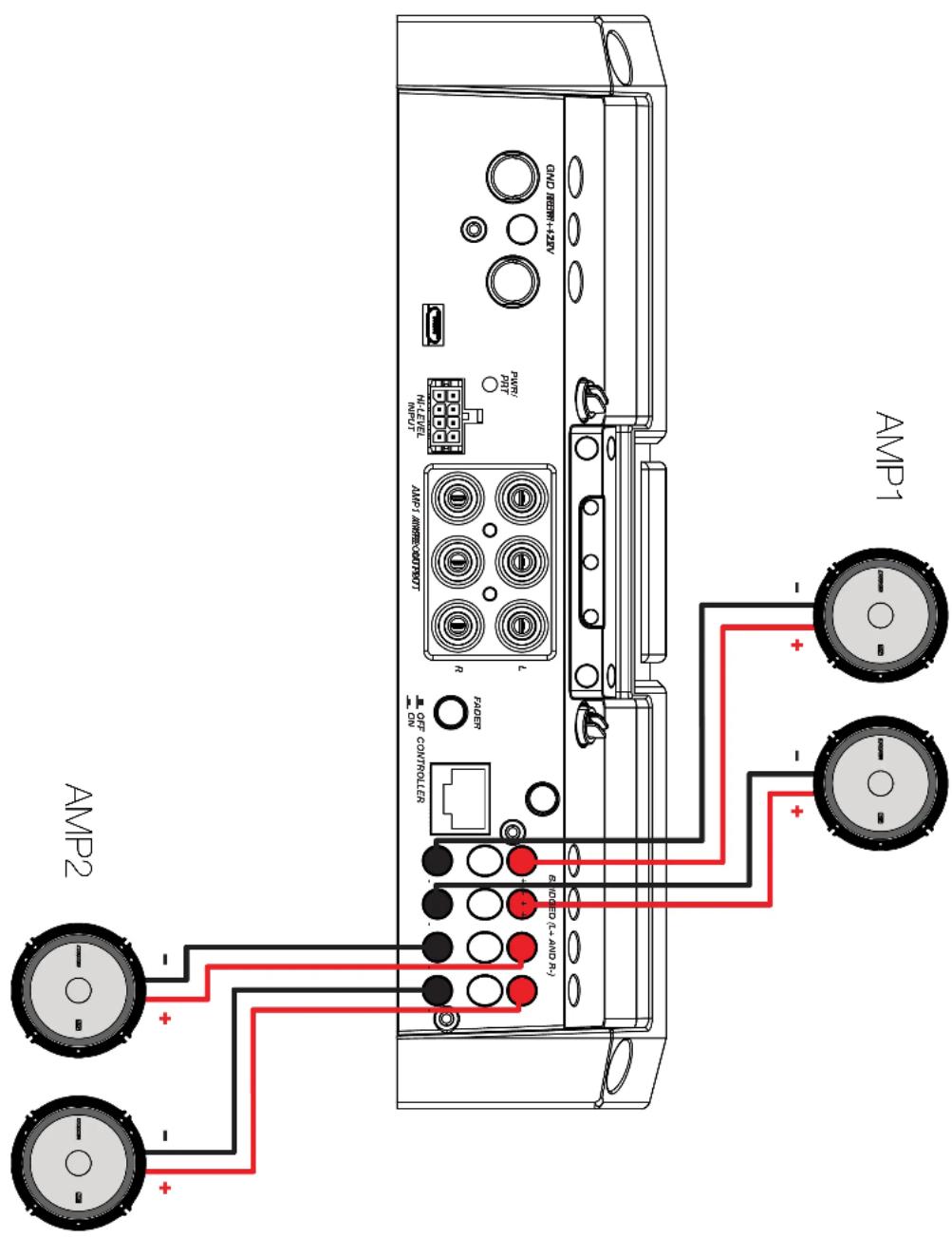
Stereo & Bridged Operation
Both stereo amplifier outputs (AMP1 & AMP2) are capable of bridged mono output. Please refer to the RMS Power Output in the specifications for bridged output power relative to impedance. Use the LEFT+ and RIGHT- terminals of the desired amplifier output to be bridged.
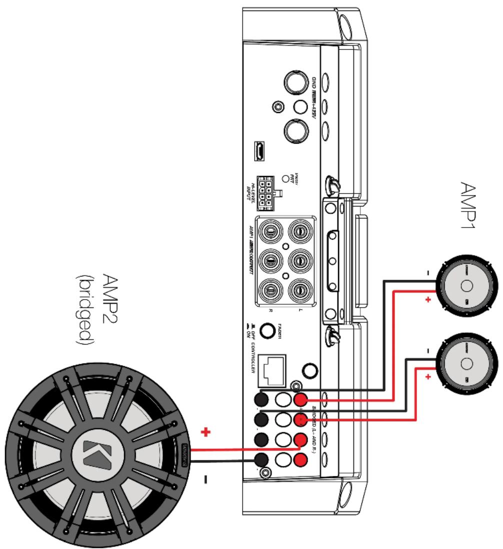
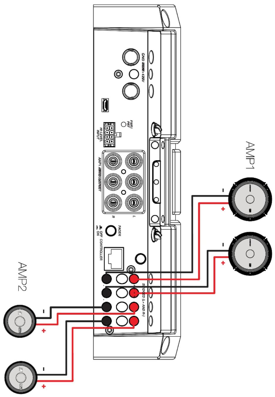
Bi-Amplification
Bi-Amplification dedicates stereo amplifier channels to specific frequency ranges to increase efficiency and headroom, greatly improving audio quality. As an example, you can use one stereo output for tweeters, and another stereo output for your mids.
Operation
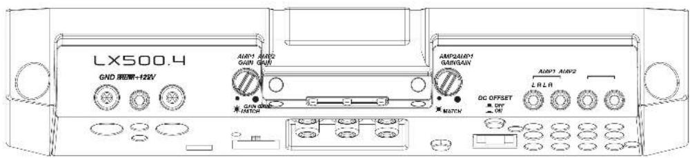
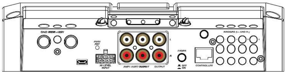
Automatic Turn-On: The LX-series offers two different automatic turn-on modes; +12V and DC Offset.
- Remote Turn-On: Run 18 gauge wire from the Remote Turn-On Lead on your source unit to the REM terminal on the LX amplifier's end panel.
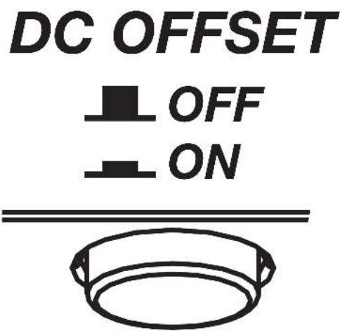
- DC Offset Turn-On: The DC Offset mode uses the Hi-Level input harness to detect >2.5V DC from the Hi-Level speaker output of the source unit when it has been turned on. To use DC offset mode, the DC OFF/ON push button must be in the ON or IN position. When using DC Offset mode, the REM terminal becomes a switched +12V output (100mA) to turn other amplifiers and devices on.
INPUT GAIN: The input gain control is not a volume control. It matches the output of the source unit to the input level of the amplifier. Maximum power out of the amplifier is possible with the gain in the lowest position. Incorrectly setting the gain can result in distorted output or damage to, and premature failure of, your speakers.
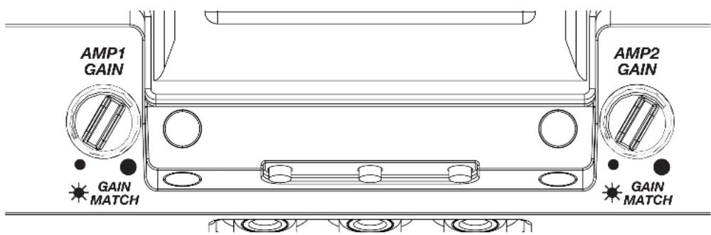
GAIN MATCHING: In any audio system, the goal is to reach maximum input and output levels without distortion or clipping. The engineers at KICKER have taken the guesswork, and hassle, out of matching the output voltage of your source unit to the amplifier with the Gain Matching feature. To begin, you'll need to download the KICKER test tones from KICKER.com.
These test tones are sine waves meant to provide a consistent signal for the amplifier to reference. The different recording levels are designed to give you the perfect gain match for your application.
OdBFS: Designed for audiophile applications to give you distortion free audio output with the most dynamic range.
-5dBFS: Designed for normal/daily applications, there will be less dynamic range but higher potential audio output levels. With this set up you can get some occasional clipping from the amplifier.
-10dBFS: Designed only for Subwoofer applications, there will be less dynamic range but higher potential audio output levels. With this set up you can get some clipping from the amplifier.
Afterwards, use the following procedure to accurately Gain Match your amplifier(s):
- Disconnect the speakers from the amplifier.
- Set all EQ and crossover settings to flat on your source unit.
- Play the downloadable file from KICKER.com
- Turn the source unit up to the maximum unclipped volume level. If you cannot accurately determine this, 34 volume is a good starting point.
- Increase the gain of the amplifier until the Gain LED turns on.
- Decrease the gain of the amplifier until the Gain LED turns off.
To use the preferred method of setting the input gain using a voltmeter or oscilloscope, begin by turning off the amplifier and disconnecting all speakers from it. Turn the gain knob completely off (counterclockwise) and all crossovers off, or to their least effective setting. If a remote bass accessory is connected to the amplifier, turn it completely on (clockwise). Ensure all EQ and DSP settings on the source unit such as bass, treble, fader, seating position etc are set to linear, flat, center, or off. Turn on the amplifier. With an oscilloscope, probe the signal coming from the source unit and play a 0dB sine wave through your source unit and increase the volume until you see the waveform clip slightly. Turn the head unit down one notch as this is the maximum unclipped volume level of your source unit. Sine wave tracks can be downloaded for free from KICKER.com under the “Support” tab. Use the 50Hz sine wave to set the gain for a subwoofer and the 1kHz sine wave for full-range speakers. Set your voltmeter or oscilloscope to measure AC voltage. Place the voltmeter’s probes on the amplifier’s speaker output terminals. With the sine wave playing, slowly turn the gain knob clockwise and watch the AC voltage on the voltmeter increase.
When the desired voltage is shown (reference power chart at KICKER.com), or you start to see the waveform square off stop increasing the gain, turn the amplifier off, reconnect all speakers and set the crossovers to your desired setting. Your gain is now set for maximum unclipped power from the amplifier. If you increase amplitude using settings on the source unit or the bass boost on the amplifier it will introduce distortion and you will need to redo these steps.
LED Accent Lighting: Remove the top panel cover to access the LED Accent Lighting Controls.

Change LED Change LED Color Brightness

Press the Change LED Color button to cycle through the available colors. Press the Change LED Brightness to change the intensity of the light, or to turn it off. Available Colors:
Red Magenta Violet Blue Light Blue Cyan Dark Green Green Yellow Orange White
Factory Reset: Remove the top panel cover to access the Factory Reset button. To restore factory settings, press and hold the Factory Reset button for 10 seconds. Turn the amplifier off and back on by cycling the ignition.

Factory Reset - Press & Hold for 10 seconds
WARNING: Factory reset will reset all settings that are controlled by LXCC to factory (including crossover)
FADER INPUT Button: Turn the FADER button ON if you are running more than a single pair of RCA inputs to the amplifier. Turn the AMP INPUT button(s) OFF if you want to drive all channels from a single input. For example, if you are using both the AMP1 and AMP2 RCA inputs, switch the FADER button to ON.
FADER

natural_image
Simple black circular ring on white background (no text or symbols)
natural_image
Simple geometric outline of a rectangular shape with no text or symbols
OFF CONTROLLER

ON
LXCC
The LXCC is a Control Center that grants access to the expanded DSP functions of the LX amplifier, allowing you to fine-tune your LX with ease.
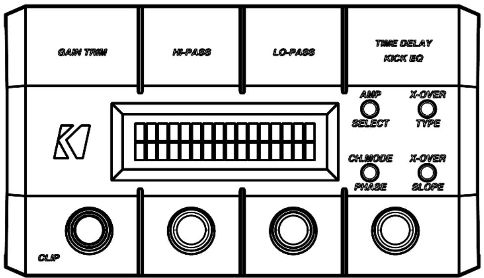
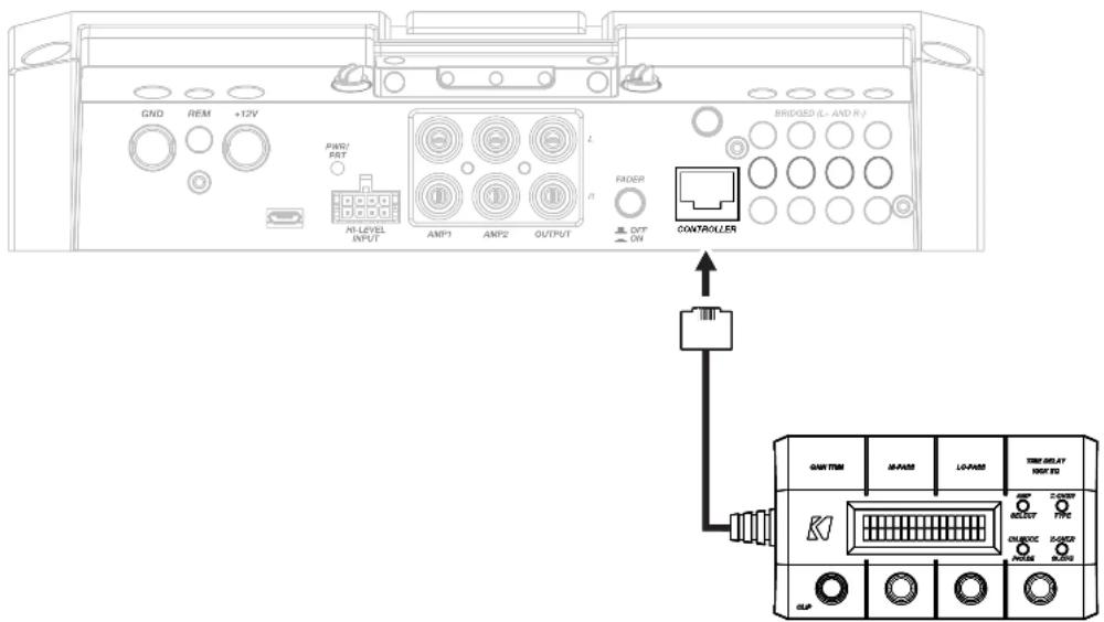
Once your LX amplifier has been installed, begin by connecting the RJ-45 cable of the LXCC to the Controller/Remote Bass input of the LX amplifier. The center display will immediately show real-time amplifier information, including amp model, amp temperature, and supplied voltage.
GAIN TRIM: Push the Gain Trim knob to open Gain Trim settings. Push the knob again or the Amp Select button to select the amplifier channel being modified. You can cut by -9dB or boost by +3dB per amplified section (AMP1 & AMP2). This allows you to make minor adjustments to levels, helping to match outputs, such as cutting your tweeter channels, while boosting the mids.
CLIP: The CLIP indicator will illuminate when the amplifier output is above the clipping threshold. This only applies to the amplifier channel currently selected (AMP SELECT). If you change your Gain, Bass Boost or SHOCwave setting, you may notice the CLIP LED become active. This means your new DSP settings have caused an output to clip and you should reduce the gain or compensate in some other way.
HI-PASS | LO-PASS: Push the HI-PASS or LO-PASS knob to open the crossover settings. Push the AMP SELECT button to select the amplifier channel being modified. The display will show the amplifier channel being modified, the current crossover (FR: Full-Range, HP: Hi-Pass, LP: Lo-Pass, BP: Band-Pass), and the crossover point.
Use the knobs to set your crossover points, between 20Hz–5kHz HP/BP and 40Hz–5kHz LP for full-range channels.
X-OVER TYPE: Select the amplifier channel for which you'd like to change the crossover type. Press the X-OVER TYPE button to choose Linkwitz-Riley or Butterworth. Each amplifier channel may have its own crossover type.
X-OVER SLOPE: Select the amplifier channel for which you'd like to change the crossover slope. Press the X-OVER SLOPE button to choose between the available slope options. Each amplifier channel may have its own crossover slope. The available slopes are - Linkwitz-Riley: 24dB, 12dB Butterworth: 24dB, 18dB, 12dB
TIME DELAY: The Time Delay will delay the left channel of the stereo outputs up to 10ms, in increments of 0.1ms. This will allow you to set the center stage according to your preferences and listening position.
Channel Mode | Phase: Use the Channel Mode button with a full-range stereo amplifier channel to change the selected channel output to stereo, L+R Summed, or L-R Summed.
Troubleshooting
If your amplifier does not appear to be working, check the obvious things first such as blown fuses, poor or incorrect wiring connections, incorrect setting of crossover switch and gain controls, etc. There are Power (PWR) & Protection (PRT) LEDs on the side panel of your KICKER LX series amplifier. Depending on the state of the amplifier and the vehicle's charging system, the LEDs will glow either green or red. When the green LED is lit, this indicates the amplifier is turned on and no trouble exists.
Green LED off, no output? With a Volt Ohm Meter (VOM) check the following: ①+12 volt power terminal (should road +12V to +16V) ②Remote turn-on terminal (should road +12V to +16V) ③Check for reversed power and ground connections ④Ground terminal, for proper conductivity.
Green LED on, no output? Check the following: ① RCA connections ② Test speaker outputs with a "known" good speaker. ③ Substitute source unit with a "known" good source unit. ④ Check for a signal in the RCA cable feeding the amplifier with the VOM meter set to measure "AC" voltage. Use a 50Hz test tone.
Red (PRT) LED flickering with loud music? The red (PRT) LED indicates low battery voltage. Check all the connections in your vehicle's charging system. It may be necessary to replace or charge your vehicle's battery or replace your vehicle's alternator.
Red (PRT) LED on, no output? ①Amplifier is very hot = thermal protection is engaged. Test for proper impedance at the speaker terminals with a VOM meter set to "DC Resistance" (see the diagrams in this manual for minimum recommended impedance and multiple speaker wiring suggestions). Also check for adequate airflow around the amplifier. ②Amplifier shuts down only while vehicle is running = voltage protection circuitry is engaged. Voltage to the amplifier is not within the 6–16 volt operating range. Have the vehicle's charging and electrical system inspected. ③Amplifier will only play at low volume levels = short circuit protection is engaged. Check for speaker wires shorted to each other or to the vehicle chassis. Check for damaged speakers or speaker(s) operating below the minimum recommended impedance.
No or low output? ① Check the balance and fader controls on source unit. ② Check the RCA (or speaker input) and speaker output connections. ③ Check the volume level on your source unit, to include the volume level of any connected phones or MP3 players.
Alternator noise-whining sound with engine's RPM? ① Check for damaged RCA (or speaker input) cable ② Check the routing of RCA (or speaker input) cable ③ Check the source unit for proper grounding ④ Check the gain settings and turn them down if they are set too high.
CAUTION: When jump starting the vehicle, be sure that connections made with jumper cables are correct. Improper connections can result in blown amplifier fuses as well as the failure of other critical systems in the vehicle.
If you have more questions about the installation or operation of your new KICKER product, see the Authorized KICKER Dealer where you made your purchase. For more advice on installation, click on the SUPPORT tab on the KICKER homepage, www.KICKER.com. Choose the TECHNICAL SUPPORT tab, choose the subject you are interested in, and then download or view the corresponding information. Please E-mail support@KICKER.com or call Technical Services (405) 624-8583 for unanswered or specific questions.
LX Multi-Channel
Specifications
Model: LX1200.5 LX1300.7
| Dynamic Power [Watts] 1500W 1500W | ||
| RMS Power Output [Watts] | ||
| @ 14.4V, 4Ω stereo, ≤ 1% THD+N | 125W X 4 AMP1, AMP2 | 125W X 4 AMP1, AMP2; 65W X 2 AMP3 |
| @ 14.4V, 2Ω stereo, ≤ 1% THD+N | 175W X 4 AMP1, AMP2 | 150W X 4 AMP1, AMP2; 65W X 2 AMP3 |
| @ 14.4V, 4Ω mono, ≤ 1% THD+N | 350W X 2 AMP1, AMP2; 300W X 1 SUB | 250W X 2 AMP1, AMP2; 130W X 1 AMP3; 300W X 1 SUB |
| @ 14.4V, 2Ω mono, < 1% THD+N | 550W X 1 SUB | 550W X 1 SUB |
| @ 14.4V, 1Ω mono, ≤ 1% THD+N | 700W X 1 SUB | 700W X 1 SUB |
Specifications Common to All Models
Frequency Response [Hz] Full-Range 20Hz–20KHz, SUB Channel 10Hz–160KHz
Selectable Electronic Crossover Selectable Crossover Slopes:
12dB and 24dB (Linkwilz-Rilcy);
12, 18 and 24dB (Butterworth)
AMP1, AMP2, AMP3 Off/HP/LP/BP
(LX Control Center HP 20Hz-5KHz, LP 40-5KHz)
SUB LP (LX Control Center LP 10Hz-160Hz)
Parametric Bass Boost Yes, LX Control Center Only, 0 - +6dB,
Variable Center Frequency 20–80 Hz, Variable Bandwidth 1–5
Fader On/Off Switch AMP2, AMP3, SUB
Variable Subsonic Filter Selectable Slope, Variable Hi-Pass 10–80Hz
Remote Bass Control Yes (Included)
Length [n, cm] 12 5/8, 32
Height [in, cm] 2 3/8, 6
Width [in, cm] 87/16, 21
Signal-to-Noise Ratio [dB] >95dB, a-weighted, re: rated power
Signal-to-Noise Ratio [dB] >75dB (ref: 1W output)
Input Sensitivity Low Level: 125mV–5V
High Level: 1V–40V
Note: All specifications and performance figures are subject to change. Please visit www.kicker.com for the most current information. To get the best performance from your new KICKER amplifier, we recommend using genuine KICKER speakers, accessories and wiring.
Mounting
Choose a structurally sound location to mount your KICKER amplifier. Make sure there are no items behind the area where the screws will be driven. Choose a location that allows at least 4" (10cm) of open ventilation for the amplifier. Drill four holes using a 7/64" (3mm) bit and use the supplied #8 screws to mount the amplifier.
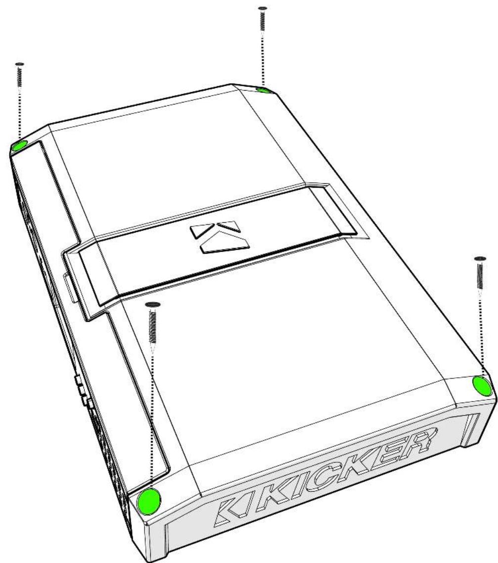
natural_image
Technical line drawing of a Kicker device casing with mounting holes and green indicator lights (no text or symbols on the diagram itself)Remove and orient the magnetized KICKER plate and badge as needed.
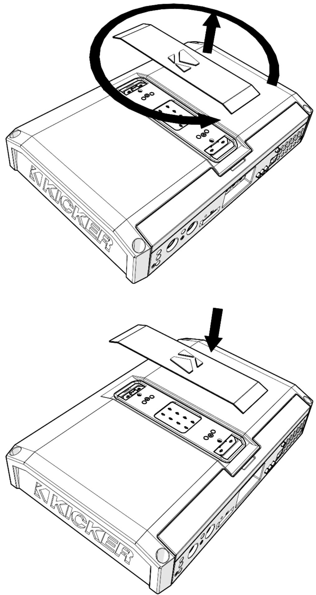
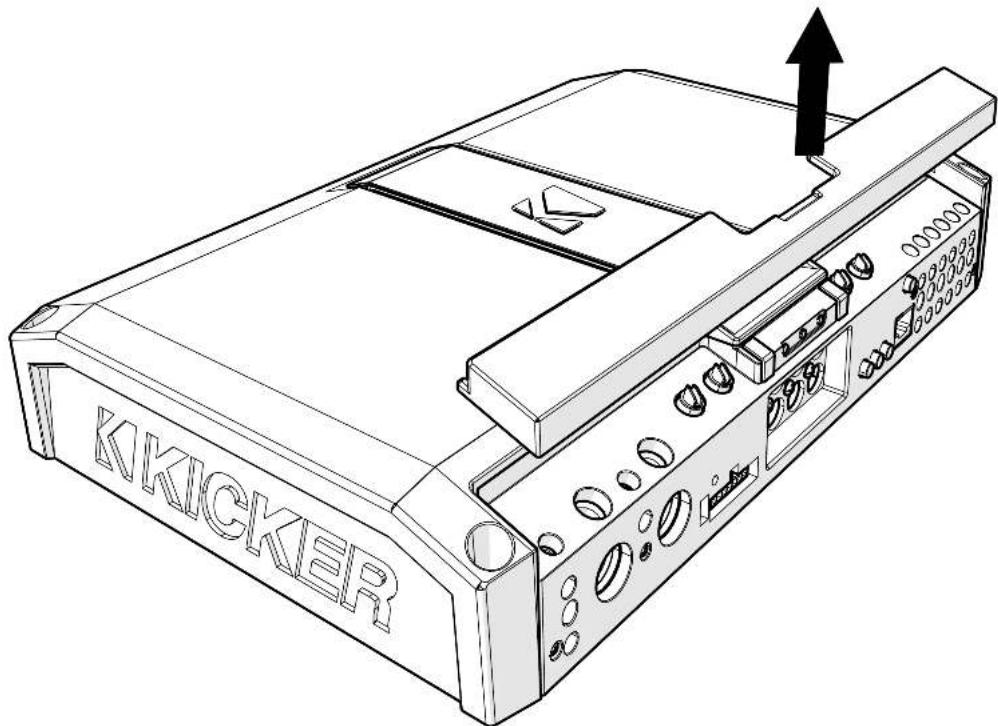
Remove the magnetized top panel cover to access the LX amplifier's power distribution and speaker output terminals, as well as gain and LED accent lighting settings.
Power Wiring
Click Here for Amplifier Install Kits
Model External Fuse (sold separately) Power/Ground Wire KICKER Wiring Kit
LX1200.5 1 x 100 Ampere 1/0 Gauge PKD1
LX1300.7 1 x 150 Ampere 1/0 Gauge PKD1
KICKER will provide a three-year warranty with all LX-Series Amplifier purchases paired with a qualifying KICKER Installation Kit*.
This extends the standard warranty by an additional year. Amplifier and Kit must be purchased from an Authorized KICKER Dealer.
Using poor-quality, under-spec wiring kits will impede LX amplifier performance.
A superior-quality KICKER installation Kit is guaranteed to extend the life of LX amplifiers.
The row extended warranty applies only to KICKER amplifiers and accessories sold to consumers by Authorized KICKER Dealers in the United States of America or its possessions. It also only applies to the original purchaser of KICKER amplifiers and accessories. One warranty extension per amplifier is allowed regardless of the number of amplifier installation kits purchased. This program does not apply to "B"-stock product or lactory-returbished product.
This offer is for a limited time, so see your local Authorized KICKER Dealer soon for details.
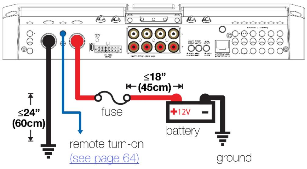
Disconnect the vehicle's battery to avoid an electrical short. A good ground connection is important. Make the ground wire short, 24" (60cm) or less and, if not conneted to the battery, connect it to a paint-and-corrosion-free, solid metal area of the vehicle's chassis. Adding an additional ground wire of this same gauge (or larger) between the battery's negative post and the vehicle chassis is recommended. Keep the audio signal cable away from factory wiring harnesses and other power wiring. If you need to cross this wiring, cross it at a 90 degree angle.
Fuse installation should be as close as possible to the battery, and no further than 18" (45cm) of the battery, and in-line with the power cable, which is connected to your LX Amplifier. Make sure the power wire is routed so that it will not be damaged, crimped, or shorted. If you ever need to remove the amplifier from the vehicle after it has been installed, the ground wire should be the last wire disconnected from the amplifier; just the opposite as when you installed it.
Pro Tip: All that's left are KS speakers, and a few cables, and you'll have an audio upgrade that will dominate any factory system! KICKER amplifiers make it easy to upgrade to solid bass with your existing or stock source unit. Ask your dealer about KICKER upgrades.
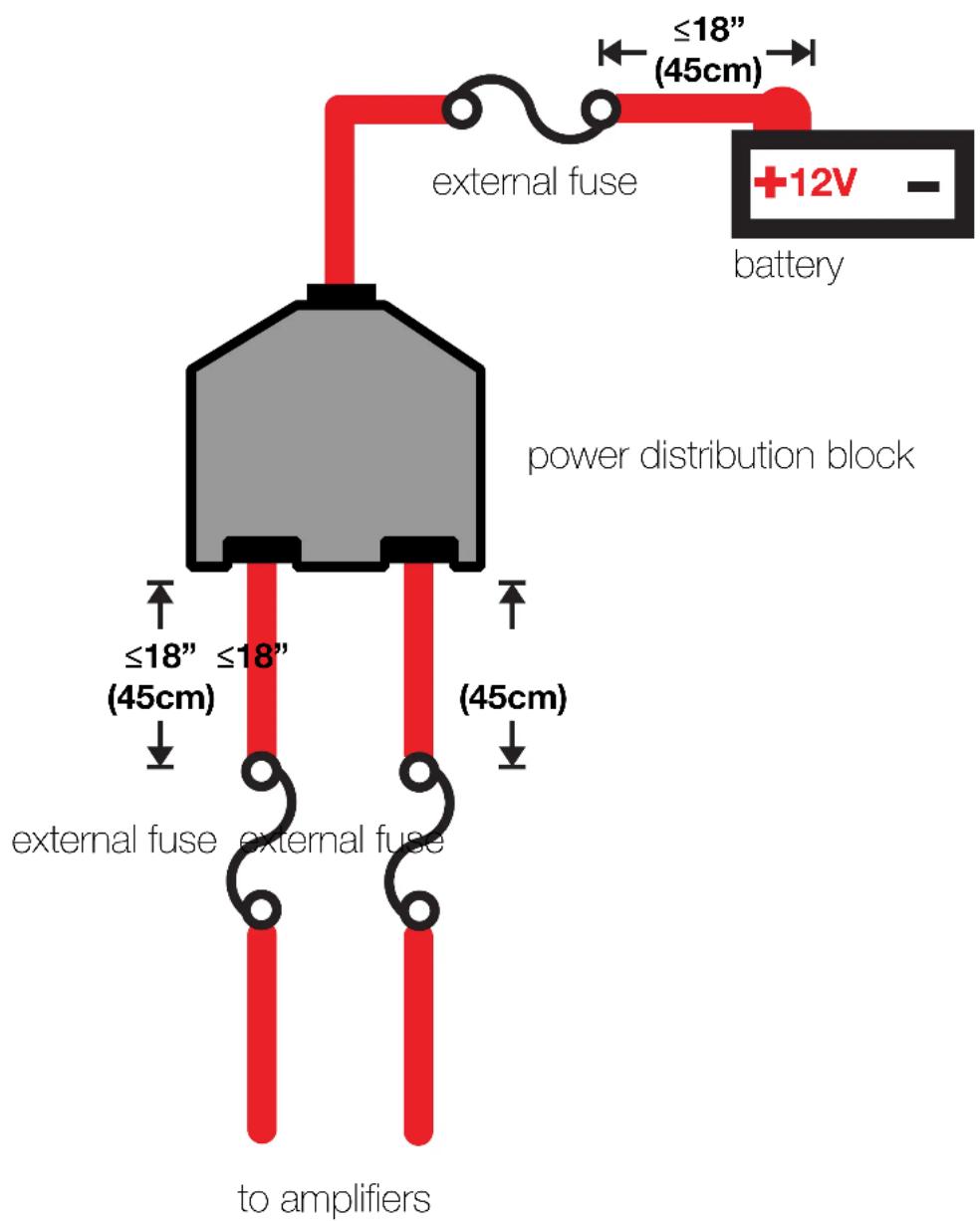
For multiple amplifier installations where distribution blocks are used, each amplifier should have its proper-rated fuse, or breaker, installed between the amplifier and the distribution block within eighteen inches of the block, or on the distribution block if it provides for fusing. The primary power wire should also be fused between the battery and distribution block, within eighteen inches of the battery's positive terminal, with a fuse or breaker rated at least to the sum of the individual amplifier's fuse values, but doesn't exceed the capacity of your wiring.
Input Wiring
The LX-series are capable of receiving both Low-level signals with the RCA inputs and Hi-level signals with the Hi-Level Input wiring harness on the front panel of the amplifier.
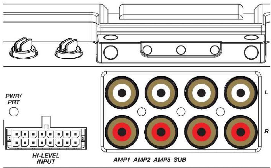
The input channel corresponding to the wiring harness colors are:
LX1200.5
AMP1 Left: White, White/Black AMP1 Right: Grey, Grey/Black AMP2 Left: Green, Green/Black AMP2 Right: Purple, Purple Black SUB Left: White, White/Black SUB Right: Grey, Grey/Black
LX1300.7
AMP1 Left: White, White/Black AMP1 Right: Grey, Grey/Black AMP2 Left: Green, Green/Black AMP2 Right: Purple, Purple Black AMP3 Left: White, White/Black AMP3 Right: Grey, Grey/Black SUB Left: Green, Green/Black SUB Right: Purple, Purple Black
Speaker Wiring
Stereo & Sub Operation
Sub Channel
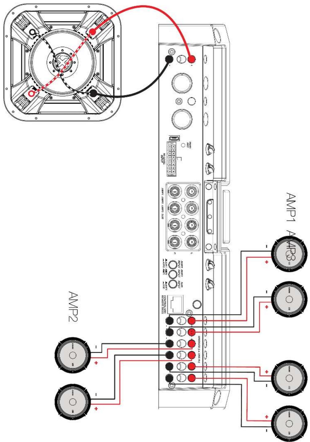
Stereo, Sub & Bridged Operation
All stereo amplifier outputs (AMP1, AMP2 & AMP3) are capable of bridged mono output. Please refer to the RMS Power Output in the specifications for bridged output power relative to impedance. Use the LEFT+ and RIGHT - terminals of the desired amplifier output to be bridged.
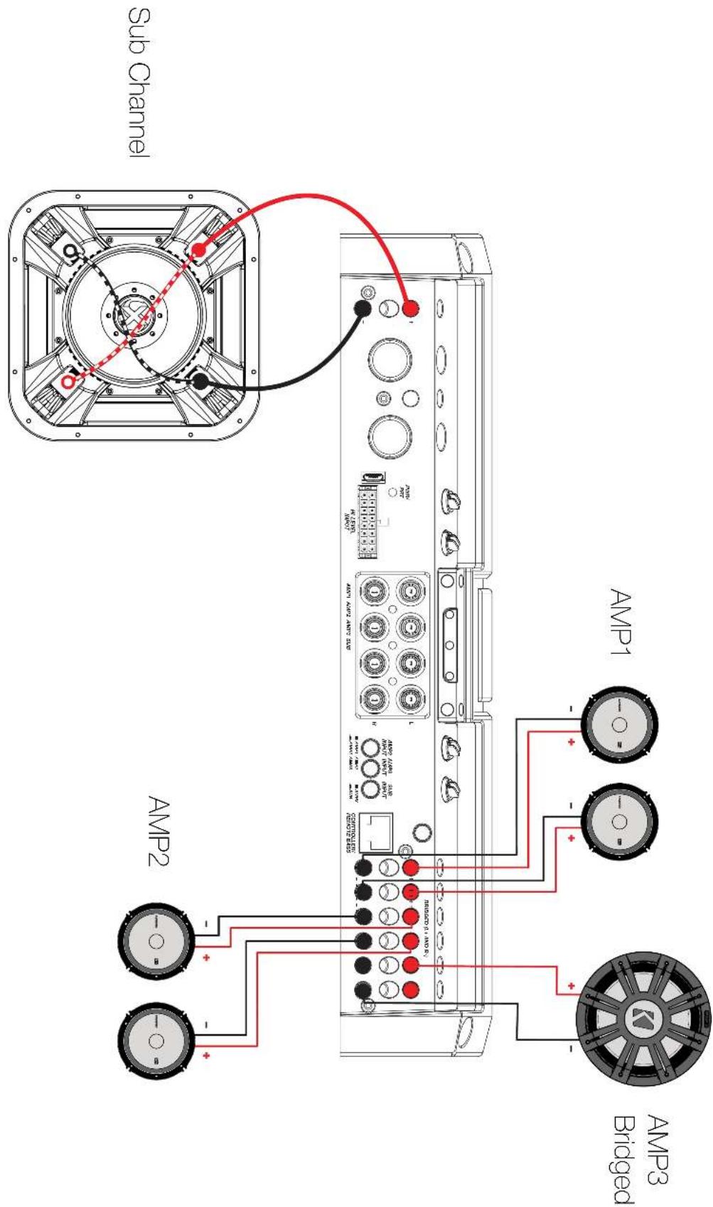
Bi-Amplification with Bridged Subwoofer
Bi-Amplification and tri-amplification dedicate stereo amplifier channels to specific frequency ranges to increase efficiency and headroom, greatly improving audio quality. As an example, you can use one stereo output for tweeters, and another stereo output for your mids.
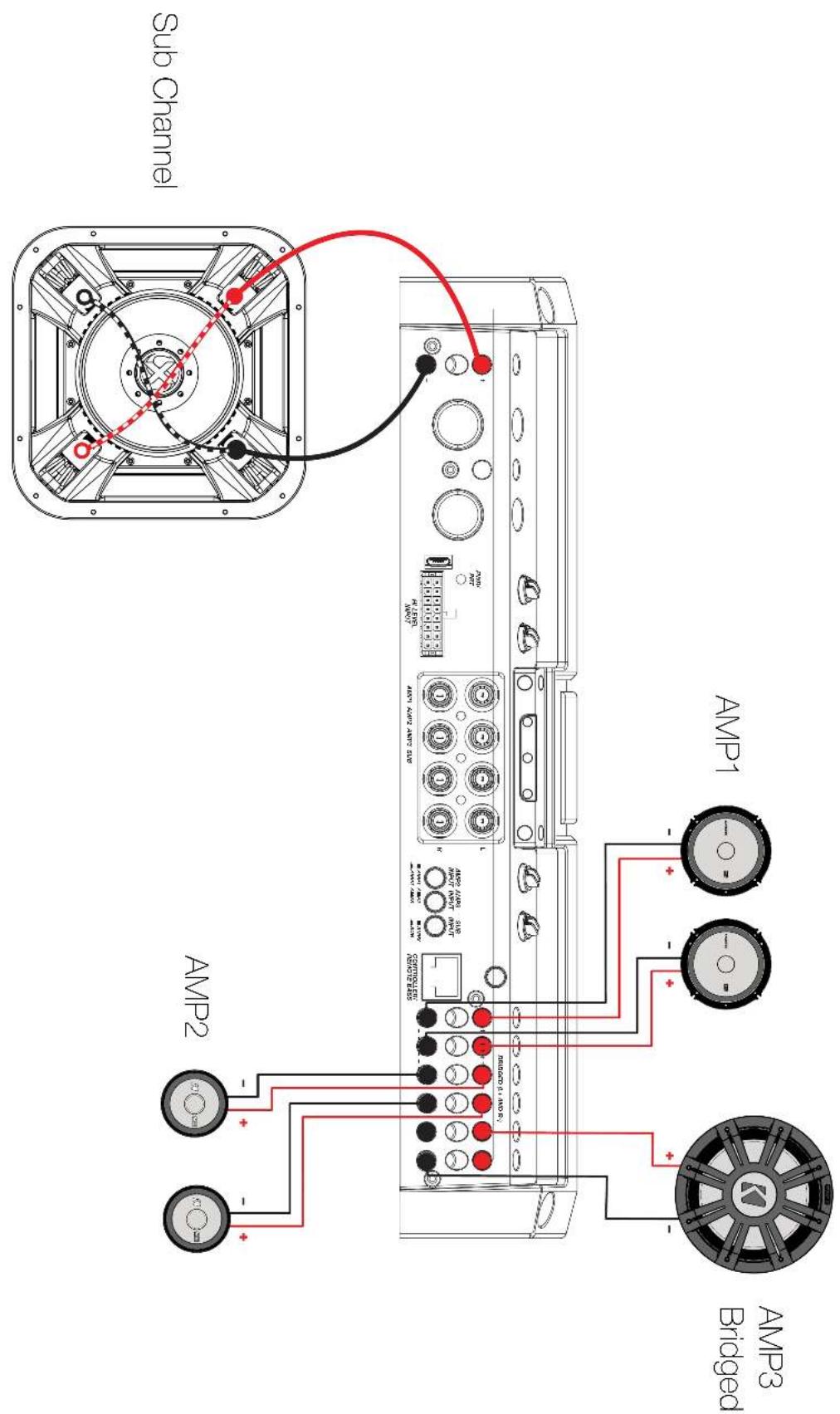
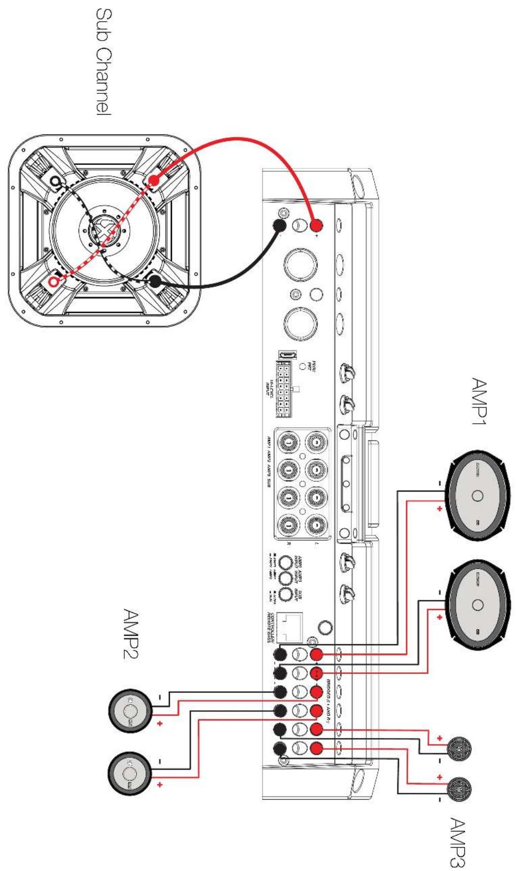
Tri-Amplification (LX1300.7 only)
As an example, the diagram below shows a tri-amplification wiring configuration using KICKER KSS693 Component Speakers, including a 6"x9", 2-3/4" mid, and 1" tweeter.


Automatic Turn-On: The LX-series offers two different automatic turn-on modes; +12V and DC Offset.
- Remote Turn-On: Run 18 gauge wire from the Remote Turn-On Lead on your source unit to the REM terminal on the LX amplifier's end panel.
- DC Offset Turn-On: The DC Offset mode uses the Hi-Level input harness to detect >2.5V DC from the Hi-Level speaker output of the source unit when it has been turned on. To use DC offset mode, the DC OFF/ON push button must be in the ON or IN position. When using DC Offset mode, the REM terminal becomes a switched +12V output (100mA) to turn other amplifiers and devices on.
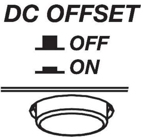
INPUT GAIN: The input gain control is not a volume control. It matches the output of the source unit to the input level of the amplifier. Maximum power out of the amplifier is possible with the gain in the lowest position. Incorrectly setting the gain can result in distorted output or damage to, and premature failure of, your speakers.
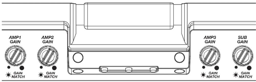
GAIN MATCHING: In any audio system, the goal is to reach maximum input and output levels without distortion or clipping. The engineers at KICKER have taken the guesswork, and hassle, out of matching the output voltage of your source unit to the amplifier with the Gain Matching feature. To begin, you'll need to download the KICKER test tones from KICKER.com.
These test tones are sine waves meant to provide a consistent signal for the amplifier to reference. The different recording levels are designed to give you the perfect gain match for your application.
OdBFS: Designed for audiophile applications to give you distortion free audio output with the most dynamic range.
-5dBFS: Designed for normal/daily applications, there will be less dynamic range but higher potential audio output levels. With this set up you can get some occasional clipping from the amplifier.
-10dBFS: Designed only for Subwoofer applications, there will be less dynamic range but higher potential audio output levels. With this set up you can get some clipping from the amplifier.
Afterwards, use the following procedure to accurately Gain Match your amplifier(s):
- Disconnect the speakers from the amplifier.
- Set all EQ and crossover settings to flat on your source unit.
- Play the downloadable file from KICKER.com
- Turn the source unit up to the maximum unclipped volume level. If you cannot accurately determine this, 34 volume is a good starting point.
- Increase the gain of the amplifier until the Gain LED turns on.
- Decrease the gain of the amplifier until the Gain LED turns off.
To use the preferred method of setting the input gain using a voltmeter or oscilloscope, begin by turning off the amplifier and disconnecting all speakers from it. Turn the gain knob completely off (counterclockwise) and all crossovers off, or to their least effective setting. If a remote bass accessory is connected to the amplifier, turn it completely on (clockwise). Ensure all EQ and DSP settings on the source unit such as bass, treble, fader, seating position etc are set to linear, flat, center, or off. Turn on the amplifier. With an oscilloscope, probe the signal coming from the source unit and play a 0dB sine wave through your source unit and increase the volume until you see the waveform clip slightly. Turn the head unit down one notch as this is the maximum unclipped volume level of your source unit. Sine wave tracks can be downloaded for free from KICKER.com under the "Support" tab. Use the 50Hz sine wave to set the gain for a subwoofer and the 1kHz sine wave for full-range speakers. Set your voltmeter or oscilloscope to measure AC voltage. Place the voltmeter's probes on the amplifier's speaker output terminals. With the sine wave playing, slowly turn the gain knob clockwise and watch the AC voltage on the voltmeter increase.
When the desired voltage is shown (reference power chart at KICKER.com), or you start to see the waveform square off stop increasing the gain, turn the amplifier off, reconnect all speakers and set the crossovers to your desired setting. Your gain is now set for maximum unclipped power from the amplifier. If you increase amplitude using settings on the source unit or the bass boost on the amplifier it will introduce distortion and you will need to redo these steps.
LED Accent Lighting: Remove the top panel cover to access the LED Accent Lighting Controls. These also control the LXRC lighting.

Change LED Change LED
Color Brightness

Press the Change LED Color button to cycle through the available colors. Press the Change LED Brightness to change the intensity of the light, or to turn it off. Available Colors:
Red Magenta Violet
Blue Light Blue Cyan
Dark Green Green Yellow
Orange White
Factory Reset: Remove the top panel cover to access the Factory Reset button. To restore factory settings, press and hold the Factory Reset button for 10 seconds. Turn the amplifier off and back on by cycling the ignition.

Factory Reset - Press & Hold for 10 seconds
WARNING: Factory reset will reset all settings that are controlled by LXCC to factory (including crossover)
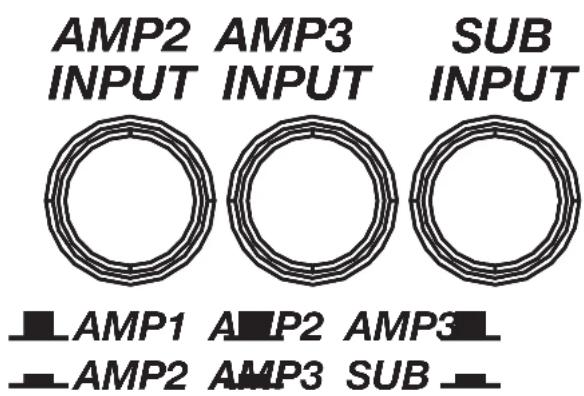
AMP/SUB INPUT Buttons: Turn the AMP INPUT Button(s) ON if you are running more than a single pair of RCA inputs to the amplifier. Turn the AMP INPUT button(s) OFF if you want to drive those channels from a single input. For example, if you are using the AMP1, AMP2, AMP3, and SUB RCA inputs, switch the AMP1/AMP2 INPUT, AMP2/AMP3 INPUT, and AMP3/SUB INPUT buttons to ON.
LXCC
The LXCC is a Control Center that grants access to the expanded DSP functions of the LX amplifier, allowing you to fine-tune your LX with ease.
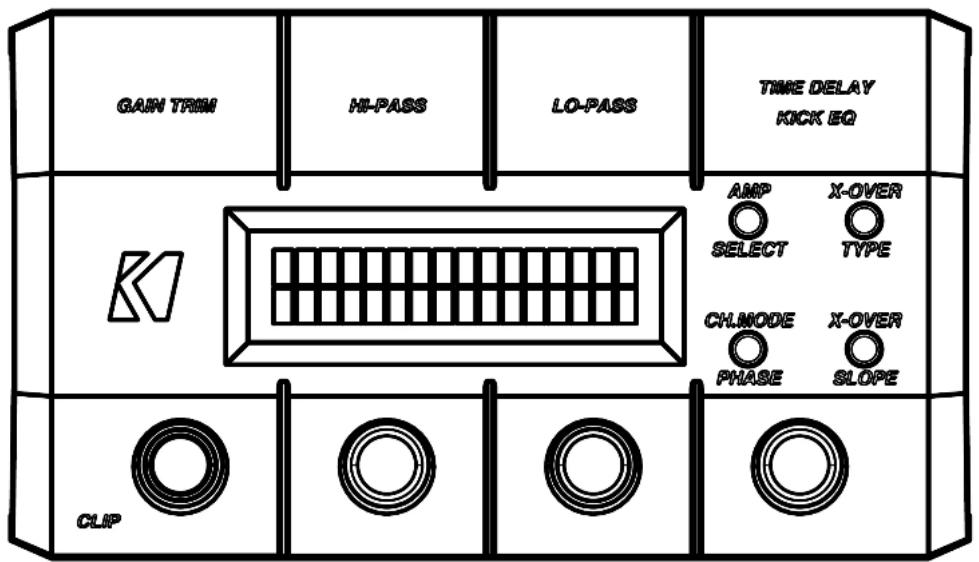
Once your LX amplifier has been installed, begin by connecting the RJ-45 cable of the LXCC to the Controller/Remote Bass input of the LX amplifier. The center display will immediately show real-time amplifier information, including amp model, amp temperature, and supplied voltage.
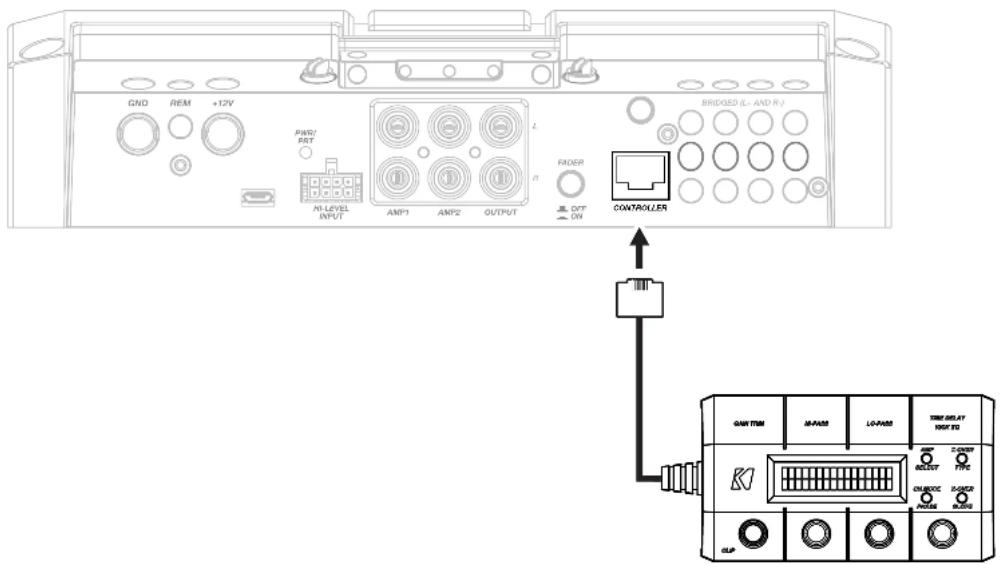
GAIN TRIM: Push the Gain Trim knob to open Gain Trim settings. Push the knob again or the Amp Select button to select the amplifier channel being modified. You can cut by -9dB or boost by +3dB per amplified section (AMP1, AMP2, AMP3, & SUB).
This allows you to make minor adjustments to levels, helping to match outputs, such as cutting your tweeter channels, while boosting the mids.
CLIP: The CLIP indicator will illuminate when the amplifier output is above the clipping threshold. This only applies to the amplifier channel currently selected (AMP SELECT). If you change your Gain, Bass Boost or SHOCwave setting, you may notice the CLIP LED become active. This means your new DSP settings have caused an output to clip and you should reduce the gain or compensate in some other way.
HI-PASS | LO-PASS: Push the HI-PASS or LO-PASS knob to open the crossover settings. Push the AMP SELECT button to select the amplifier channel being modified. The display will show the amplifier channel being modified, the current crossover (FR: Full-Range, HP: Hi-Pass, LP: Lo-Pass, BP: Band-Pass), and the crossover point.
Use the knobs to set your crossover points, between 20Hz–5kHz HP/BP and 40Hz–5kHz LP for full-range channels, or 10Hz–160Hz for a subwoofer channel. Using a Hi-Pass filter on a subwoofer channel will engage the subsonic filter.
X-OVER TYPE: Select the amplifier channel for which you'd like to change the crossover type. Press the X-OVER TYPE button to choose Linkwitz-Riley or Butterworth. Each amplifier channel may have its own crossover type.
X-OVER SLOPE: Select the amplifier channel for which you'd like to change the crossover slope. Press the X-OVER SLOPE button to choose between the available slope options. Each amplifier channel may have its own crossover slope. The available slopes are:
TIME DELAY: The Time Delay will delay the left channel of the stereo outputs up to 10ms, in increments of 0.1ms. This will allow you to set the center stage according to your preferences and listening position.
KICK EQ Parametric Bass Boost:
When the subwoofer channel is selected, the TIME DELAY knob will instead become a KICK EQ Parametric Bass Boost for the subwoofer channel. This boost is independent of the GAIN TRIM setting, and may be set from 0dB–6dB. Press the knob to set the amount of boost. Press it a second time to choose the center frequency to which the boost is applied. Press it a third time to set the bandwidth (Q) of the center frequency, from 1–5 in increments of 0.1.
Channel Mode | Phase: Use the Channel
Mode button with a full-range stereo amplifier channel to change the selected channel output to stereo, L+R Summed, or L-R Summed.
Use the PHASE setting with a subwoofer channel to select the phasing; 0°, or 180°. If you are experiencing an absence of bass in the audio, the bass frequency may be out of phase with the rest of the system. Reversing positive/negative polarity, or changing subwoofer location may also resolve these types of issues.
LXRC Installation
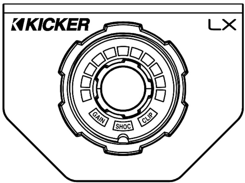
The LXRC is a multi-function remote bass knob that further expands the DSP features of the LX amplifier, with access to LED lighting changes, real-time battery input voltage monitoring, clip output indication, and KICKER's proprietary SHOCwave 2.0 (Sub-Harmonic Octave Creation) algorithm.
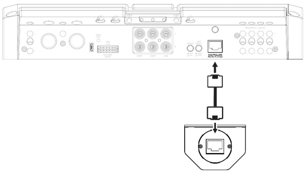
Disconnect the supplied RJ-45 cable used to fine-tune with the LXCC, then connect from the back of the LXRC to the Remote Bass jack of the LX amplifier.
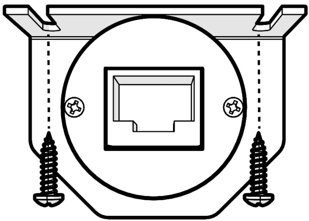
Surface Mounting: To surface mount the LXRC, place the LXRC against a surface and secure the mounting bracket using the supplied screws.
natural_image
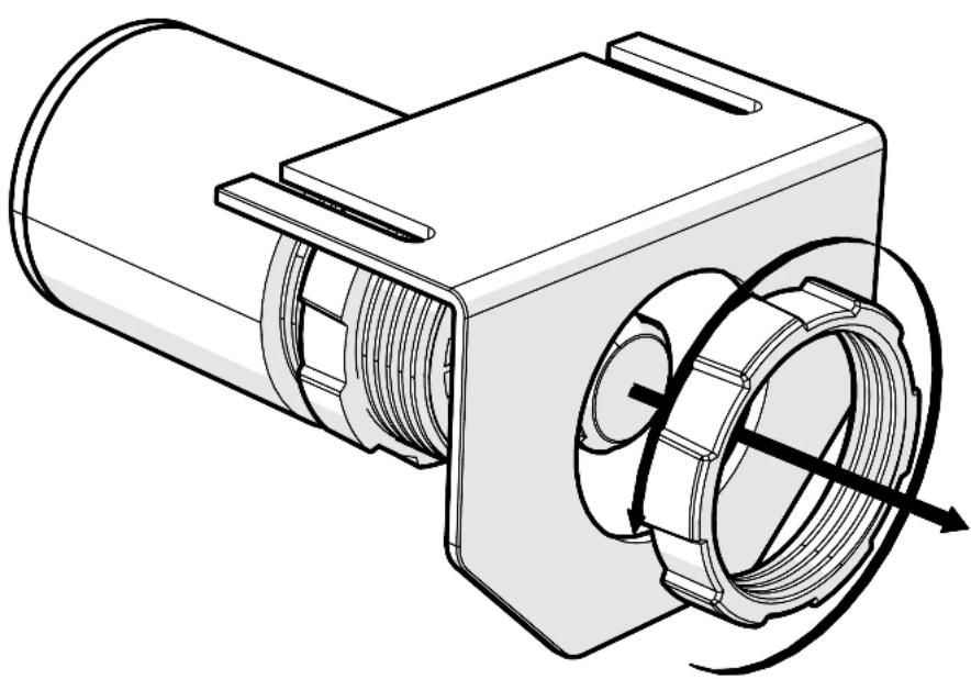
Technical diagram of a mechanical component with screw fasteners and a central square housing (no text or symbols)Flush Mounting: To flush mount the LXRC behind a mounting surface, begin by cutting a 1-inch diameter hole in the mounting surface, being careful not to drill through existing wiring or mechanisms.
Remove the LXRC front mounting nut and mounting bracket.
natural_image
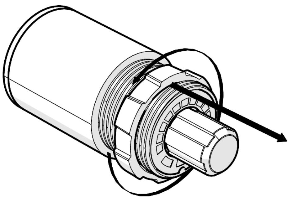
Technical line drawing of a mechanical component with internal threading and housing (no text or symbols)Adjust the rear mounting nut forward to set the protrusion of the LXRC knob.
natural_image
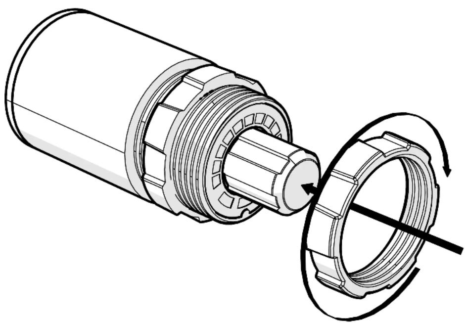
Technical illustration of a mechanical assembly with internal gears and a directional arrow (no text or symbols)Place the LXRC through the mounting hole, then reattach the front mounting nut to secure the remote against the mounting surface.
natural_image
Technical illustration of a mechanical assembly showing a cylindrical component being inserted into a bearing housing with rotating shafts (no text or symbols)Connect the LXRC to the Remote Bass jack of the LX amplifier.
LXRC Operation
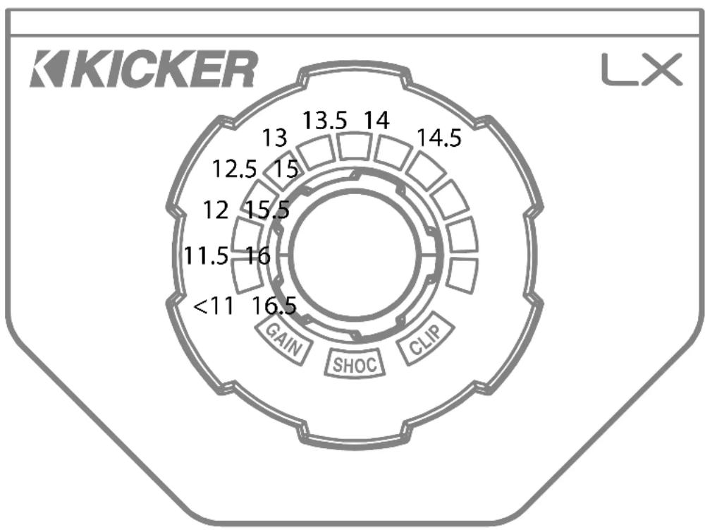
The LXRC serves as both a rotary knob for precise adjustments and as a multi-function push-button to change modes, with an illuminated LED ring to display the current setting. You may cycle through most modes by pressing and holding the button for <3 seconds (short-press). Once adjustments have been made, wait for the LXRC to save the settings and return to the default Voltage Indication mode.
Voltage: The LXRC will default to showing the input voltage, with the remote knob LED ring serving as a VU meter for 11V–16V. To enter Input Voltage Indication mode, perform a short-press until the menu cycles, perform no interaction for 5 seconds.
other
| Category | Value | | -------- | ----- | | GAIN | 16.5 | | SHOC | 15.5 | | CLIP | 14.5 | | Other | 13.5 | | Unknown | 14.0 | | Unknown | 13.0 | | Unknown | 12.5 | | Unknown | 12.0 | | Unknown | 11.5 | | Unknown | <11 |Gain (Remote Level): The LXRC gain control is a gain attenuator from -26dB to 0dB. This will allow you to conveniently adjust the gain of the subwoofer channel on the fly, with the maximum being the gain setting you've selected on the LX amplifier top panel. To enter Remote Level mode, turn the knob while in Voltage mode, or short-press the knob until the menu reaches Gain.
SHOCwave™ 2.0: The SHOCwave (Sub Harmonic Octave Creation) will restore low frequencies that are weaker in older recordings or lost in data compression. The SUBWOOFER channel must be operating with a full-range signal for this effect to work properly. Short-Press & hold the knob until SHOC is illuminated, then adjust the knob to a level that is satisfactory.
Brightness: Enter the Brightness adjustment mode by pressing and holding the LXRC button for >3 seconds (long-press). Rotate the knob to adjust the brightness to a satisfactory level, then perform no action for 5 seconds and the LXRC will return to default voltage mode. While in voltage mode, if you double-press the remote button the LXRC LED array will turn on/off.
Clip: The CLIP display serves as a global clip indicator to show when a clipped output signal is detected. If you change your Gain or SHOCwave setting, you may notice the CLIP LED become active. This means your new DSP settings have caused an output to clip and you should reduce the gain or compensate in some other way.
Troubleshooting
If your amplifier does not appear to be working, check the obvious things first such as blown fuses, poor or incorrect wiring connections, incorrect setting of crossover switch and gain controls, etc. There are Power (PWR) & Protection (PRT) LEDs on the side panel of your KICKER LX series amplifier. Depending on the state of the amplifier and the vehicle's charging system, the LEDs will glow either green or red. When the green LED is lit, this indicates the amplifier is turned on and no trouble exists.
Green LED off, no output? With a Volt Ohm Meter (VOM) check the following: ①+12 volt power terminal (should road +12V to +16V) ②Remote turn-on terminal (should road +12V to +16V) ③Check for reversed power and ground connections ④Ground terminal, for proper conductivity.
Green LED on, no output? Check the following: ① RCA connections ② Test speaker outputs with a "known" good speaker. ③ Substitute source unit with a "known" good source unit. ④ Check for a signal in the RCA cable feeding the amplifier with the VOM meter set to measure "AC" voltage. Use a 50Hz test tone.
Red (PRT) LED flickering with loud music? The red (PRT) LED indicates low battery voltage. Check all the connections in your vehicle's charging system. It may be necessary to replace or charge your vehicle's battery or replace your vehicle's alternator.
Red (PRT) LED on, no output? ①Amplifier is very hot = thermal protection is engaged. Test for proper impedance at the speaker terminals with a VOM meter set to "DC Resistance" (see the diagrams in this manual for minimum recommended impedance and multiple speaker wiring suggestions). Also check for adequate airflow around the amplifier. ②Amplifier shuts down only while vehicle is running = voltage protection circuitry is engaged. Voltage to the amplifier is not within the 6–16 volt operating range. Have the vehicle's charging and electrical system inspected. ③Amplifier will only play at low volume levels = short circuit protection is engaged. Check for speaker wires shorted to each other or to the vehicle chassis. Check for damaged speakers or speaker(s) operating below the minimum recommended impedance.
No or low output? ① Check the balance and fader controls on source unit. ② Check the RCA (or speaker input) and speaker output connections. ③ Check the volume level on your source unit, to include the volume level of any connected phones or MP3 players.
Alternator noise-whining sound with engine's RPM? ① Check for damaged RCA (or speaker input) cable ② Check the routing of RCA (or speaker input) cable ③ Check the source unit for proper grounding ④ Check the gain settings and turn them down if they are set too high.
CAUTION: When jump starting the vehicle, be sure that connections made with jumper cables are correct. Improper connections can result in blown amplifier fuses as well as the failure of other critical systems in the vehicle.
If you have more questions about the installation or operation of your new KICKER product, see the Authorized KICKER Dealer where you made your purchase. For more advice on installation, click on the SUPPORT tab on the KICKER homepage, www.KICKER.com. Choose the TECHNICAL SUPPORT tab, choose the subject you are interested in, and then download or view the corresponding information. Please E-mail support@KICKER.com or call Technical Services (405) 624-8583 for unanswered or specific questions.
The RMA number must be clearly marked on the outside of the package. Please return only defective components. The return of functioning items increases your return freight charges. Non-defective items will be returned freight collect to you. For example, if a subwoofer is defective, only return the defective subwoofer, not the entire enclosure. Include a copy of the original receipt with the purchase date clearly visible, and a “proof-of-purchase” statement listing the Customer’s name, Dealer’s name and invoice number, and product purchased. Warranty expiration on items without proof-of-purchase will be determined from the type of sale and manufacturing date code. Freight must be prepaid; items sent freight-collect, or COD, will be refused.
WHAT IS NOT COVERED?
This warranty is valid only if the product is used for the purpose for which it was designed. It does not cover:
o Damage due to improper installation
o Subsequent damage to other components
o Damage caused by excessive heat, chemical cleaners, and/or UV radiation
o Damage through negligence, misuse, accident or abuse. Repeated returns for the same damage may be considered abuse
o Any cost or expense related to the removal or reinstallation of product
o Speakers damaged due to amplifier clipping or distortion
o Items previously repaired or modified by any unauthorized repair facility
o Return shipping on non-defective items
o Products with tampered or missing barcode labels
o Products with tampered or missing serial numbers
o Products returned without a Return Merchandise Authorization (RMA) number
o Products purchased from an UNAUTHORIZED dealer
o Freight Damage
o The cost of shipping product to KICKER
o Service performed by anyone other than KICKER
HOW LONG WILL IT TAKE?
KICKER strives to maintain a goal of one week turnaround for all electronics (amplifiers, crossovers, equalizers, etc.) returns. Delays may be incurred if lack of replacement inventory or parts is encountered. Failure to follow these steps may void your warranty. Any questions can be directed to the KICKER Customer Service Department at (405) 624-8510. Contact your International KICKER dealer or distributor concerning specific procedures for your country's warranty policies.
Contact your International KICKER dealer or distributor concerning specific procedures for your country's warranty policies.
Our goods come with guarantees that cannot be excluded under the Australian Consumer Law. You are entitled to a replacement or refund for a major failure and for compensation for any other reasonably foreseeable loss or damage. You are also entitled to have the goods repaired or replaced if the goods fail to be of acceptable quality and the failure does not amount to a major failure.
- IMPORTANT SAFETY WARNING
- LX Mono
- Specifications
- Model: LX850.1 LX1250.1
- Specifications Common to All Models
- Model: LX1650.1 LX3000.1
- Mounting
- Power Wiring
- Click Here for Amplifier Install Kits
- Input Wiring
- Subwoofer Wiring
- Single 2Ω Dual Voice Coil L7X Subwoofer wired in parallel.
- Two 1Ω Dual Voice Coil L7X Subwoofers wired in Series/Parallel
- Operation
- LX850.1
- KICK EQ Parametric Bass Boost:
- LO-PASS FREQ (Crossover Control):
- LXRC Installation
- LXRC Operation
- Troubleshooting
- LX Stereo
- Speaker Wiring
- Stereo Operation
- Stereo & Bridged Operation
- Bi-Amplification
- LXCC
- LX Multi-Channel
- Stereo, Sub & Bridged Operation
- Bi-Amplification with Bridged Subwoofer
- Tri-Amplification (LX1300.7 only)
- Channel Mode | Phase: Use the Channel
- WHAT IS NOT COVERED?
- HOW LONG WILL IT TAKE?
Brand : KICKER
Model : LX1300.7
Category : Receiver