
TAU3 - Measuring instrument Megger - Free user manual and instructions
Find the device manual for free TAU3 Megger in PDF.


| Product Type | Transformer Turns Ratio Tester |
| Brand | Megger |
| Model | TAU3 |
| Dimensions (H x W x D) | 170 x 100 x 55 mm |
| Weight | 0.6 kg (including batteries) |
| Power Supply | 6 x 1.5 V AA alkaline batteries or rechargeable NiMH |
| Battery Life | Approximately 8 hours of continuous use |
| Measurement Range (Turns Ratio) | 0.8 to 2000 |
| Accuracy | ±0.1% of reading |
| Test Voltage | 40 V AC maximum |
| Display | Backlit LCD, 4-line, 16 characters per line |
| Memory | Up to 200 test results |
| Interfaces | USB 2.0 for data transfer |
| Operating Temperature | -10°C to +50°C |
| Storage Temperature | -20°C to +60°C |
| Humidity Range | 0 to 95% non-condensing |
| Safety Standards | IEC 61010-1, CAT II 300 V |
| Ingress Protection | IP40 |
| Main Functions | Turns ratio, phase displacement, excitation current, winding resistance |
| Spare Parts & Repairability | Available through authorized Megger service centers |
| Maintenance & Cleaning | Wipe with a damp cloth; no solvents; calibrate annually |
| General Information | Portable, rugged design for field use; complete with test leads and soft carry case |
Frequently Asked Questions - TAU3 Megger
User questions about TAU3 Megger
0 question about this device. Answer the ones you know or ask your own.
Ask a new question about this device
Download the instructions for your Measuring instrument in PDF format for free! Find your manual TAU3 - Megger and take your electronic device back in hand. On this page are published all the documents necessary for the use of your device. TAU3 by Megger.
USER MANUAL TAU3 Megger
True Three Phase Transformer Analyzer
USER MANUAL
EN - ENGLISH
Notice
The information presented in this manual is adequate for the intended use of the product. Use of the product or its individual instruments for purposes other than those specified herein requires confirmation of their validity and suitability from Megger. Refer to the warranty information below. Specifications are subject to change without notice.
WARRANTY
Products supplied by Megger are warranted against defects in material and workmanship for a period of 1 years following shipment. The warranty is void in the event of abuse (failure to follow recommended operating procedures) or failure by the customer to perform specific maintenance as indicated in this manual.
Megger
400 Opportunity Way
Phoenixville, PA 19460
610-676-8500 (Telephone)
610-676-8610 (Fax)
www.megger.com
Contents
Notice....2
Table of Contents....3
Introduction....5
Item received....6
Warnings and safety precautions....13
Technical specifications....15
Connections and controls 18
PC software installation....19
PC software update....22
PowerDB installation....24
Initialization....25
About 26
Settings....27
Measurements & Limits Settings....28
Nameplate....29
Turns Ratio....30
Resistance ....31
Efficiency....32
Regional....33
OLTC Control....34
Display....35
Administrative & Maintenance....36
Table of Contents
Quick Test....37
Confirm Vector....38
Vector, Phases, and Nameplate....39
Select Vector and Select Phases to Test....40
Nameplate 41
Turns Ratio & Balance 42
Winding Resistance & Demagnetization....45
Short Circuit Impedance 48
Efficiency....50
All tests....51
Save, Print, Export, Retest, Home, Test Setup ....52
Results ....53
Asset Template 55
Template Test ....58
Single tab test 61
Multiple Tap OLTC AC Tests....62
Multiple Tap OLTC Winding Resistance Tests....63
Multiple Tap OLTC All Tests....65
PowerDB Import 66
Service 67
Maintenance 68
Introduction
Thank you for your purchase of the Megger TAU3 True Three Phase Transformer Analyzer. The TAU3 design emphasizes safety, reliability, and ease of use. It will provide you with the information you need to test power, distribution, and instrument transformers and make informed electromechanical maintenance decisions
Purpose of this manual
This document is the user manual for the Megger TAU3 True Three Phase Transformer Analyzer. It provides a description of the instrument as well as operating instructions. Read this manual before using the equipment, with special emphasis on all safety discussions.
Audience
This manual is for technical personnel who are familiar with the various transformer measurements performed by electrical test equipment and have a general understanding of their use and operation. Such personnel should also be thoroughly familiar with the hazards associated with the use of this equipment and should have received proper safety training.
If you find any discrepancies in the TAU3 manual or have any comments, please send them to Megger via fax, e-mail, or phone.
Megger
400 Opportunity Way
Phoenixville, PA 19460
610-676-8500 (Telephone)
610-676-8610 (Fax)
USTechSupportGrp@megger.com
For technical support, please consult the Megger web site at www.megger.com for the local distributor near you.
Item received
TAU3 Models
| Part Number Description Image | ||
| TAU3-BASIC | 62.5 VAC / 10 ADC three phase switched multifunction turns ratiometer and winding resistance ohmmeter test set | 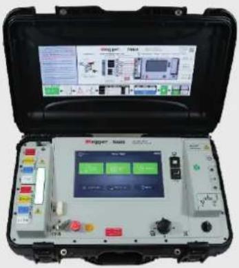 |
| TAU3-ADV | 125 VAC / 16 ADC true three phase multifunction turns ratiometer, winding resistance ohmmeter, and short circuit impedance/leakage reactance test set | |
| TAU3-PRO | 250 VAC / 32 ADC true three phase multifunction turns ratiometer, winding resistance ohmmeter, and short circuit impedance/leakage reactance test set | |
| TAU3-EXP | 250 VAC / 32 ADC true three phase multifunction turns ratiometer, winding resistance ohmmeter, and short circuit impedance/leakage reactance test set with select optional hardware and software accessories included |
| Model Differentiation | TAU3-BASIC | TAU3-ADV | TAU3-PRO | TAU3-EXP |
| Integrated display | 10.1" Included | |||
| Confirm Vector | Included | |||
| Winding Resistance Maximum Excitation Voltage - DC | 50 V | 100 V | ||
| TTR Maximum Current - AC | 3.5 A | 11 A | ||
| TTR Max Induced Voltage - AC | 62.5 V | 125 V | 250 V | |
| Winding Resistance Maximum Current- DC | 10 A | 16 A | 32 A | |
| True 3 Phase Excitation and Measurement | N/A | Included | ||
| Phase Shifting Tx's Measurement | Included | |||
| Short Circuit Impedance / Leakage Reactance | Included | |||
| FRSL | Optional | Included | ||
| PowerDB Control | Optional | Included | ||
TAU3-BASIC and TAU3-ADV Leads
| Part Number Description Image | ||
| 2008-15KIT2 16 A H & X leads. 5 m (15 ft) |  | |
| 2008-30KIT2 16 A H & X leads. 9 m (15 ft) | ||
| 2008-60KIT2 16 A H & X leads. 18 m (15 ft) | ||
| 2008-100KIT2 | 16 A H & X leads. 30 m (100 ft) H leads and 18 m (60 ft) X leads | 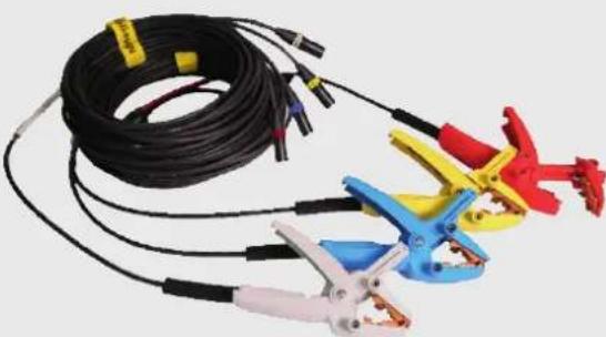 |
| 2008-30XKIT2 16 A H & X lead extensions. 9 m (30 ft) |  | |
 | ||
| 2008-15KIT3 16 A H & 32 A X leads. 5 m (15 ft) |  | |
| 2008-30KIT3 16 A H & 32 A X leads. 9 m (15 ft) | ||
| 2008-60KIT3 16 A H & 32 A X leads. 18 m (15 ft) | ||
| 2008-100KIT3 | 16 A H & 32 A X leads. 30 m (100 ft)H leads and 18 m (60 ft) X leads. |  |
| 2008-30XKIT3 | 16 A H & 32 A X lead extensions.9 m (30 ft) |  |
 | ||
| Part Number Description Image | |
| 1014-927 AC Power Cords |  |
| CA-USB USB 2.0 Cable |  |
| 1011-622 OLTC Tap Changer Cable |  |
| 2012-180 Cable Bag – Back Pack (qty 2) |  |
| 4702-7 Ground Lead |  |
Item received
| Part Number Description Image | |
| 90012-878 Blank Thumb Drive |  |
Optional software accessories
| Part Number Description |
| SW-POWERDB PowerDB Control |
| SW-CUSTOMAPP Custom application control |
| SW-EFFICIENCY Transformer load, no-load, and efficiency measurements |
| SW-FRSL Frequency response stray losses |
| SW-DRM Dynamic resistance measurements |
| SW-DRYOUT Transformer dry out / winding temperature measurements |
| SW-HEATRUN Transformer heat run / cool down measurements |
Optional hardware accessories
| Part Number Description Image | ||
| TAU3-CAL-CERT | TAU3 Calibration Certificate | |
| 1004-639 | Safety Beacon – 18 m (60 ft) |  |
| 1014-928 | Transit Case (for instrument) |  |
| 90029-537 USB Printer |  | |
| 90029-573-P USB Printer Paper (48 rolls) |  | |
| 2005-249 1:1 Test Jig |  | |
| 1011-622-A OLTC tap changer cable adapters |  | |
| TRS1PLUS TRS1+ turns ratio calibration standard | 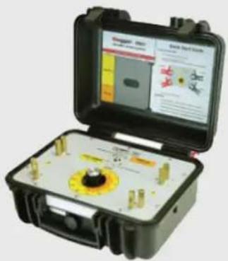 | |
| TOS1 TOS1 resistance calibration standard |  |
ORDERING INFORMATION
Item (Qty) Cat. No.
TAU3 BASIC and ADV lead sets
16 Amp H leads with red jacket and red, yellow, blue, and white clamps (4 total)
16 Amp X leads with black jacket and red, yellow, blue, and white clamps (4 total)
5 m (15 ft) H and X leads 2008-15KIT2
9 m (30 ft) H and X leads 2008-30KIT2
18 m (60 ft) H and X leads 2008-60KIT2
30 m (100 ft) H and 18 m (60 ft) X leads 2008-100KIT2
Optional Lead Accessories
TAU3 BASIC and ADV 16 A H and 16 A X lead extensions
9 m (30 ft) H and X extensions 2008-30XKIT2
Included Accessories - BASIC, ADV, PRO, EXP
AC Power Cords (US, EU, UK) 1014-927
USB 2.0 Cable CA-USB
OLTC Tap Changer Cable 1011-622
Cable Bag - Backpack 2012-180
Ground Lead 4.5m (15 ft) 4702-7
Thumb Drive 90012-878
Included accessories - EXP
Second Cable Bag - Backpack 2012-180
OLTC Tap changer cable adapters 1011-622-A
USB printer 90029-573
Safety beacon - 18 m (60 ft) 1004-639
Included accessories - PRO
Second Cable Bag - Backpack 2012-180
Optional Software Accessories
PowerDB control SW-POWERDB
Custom application control SW-CUSTOMAPP
Transformer efficiency measurements* SW-EFFICIENCY
Item (Qty) Cat. No.
Frequency response stray losses measurements SW-FRSL
Dynamic resistance measurements* SW-DRM
Transformer dry out measurements* SW-DRYOUT
Transformer heat run measurements* SW-HEATRUN
Item (Qty) For Price List Cat. No.
TAU3 PRO and EXP lead sets
16 Amp H leads with red jacket and red, yellow, blue, and white clamps (4 total)
32 Amp X leads with black and white stripe jacket and red, yellow, blue, and white clamps (4 total)
5 m (15 ft) H and X leads 2008-15KIT3
9 m (30 ft) H and X leads 2008-30KIT3
18 m (60 ft) H and X leads 2008-60KIT3
30 m (100 ft) H and 18 m (60 ft) X leads 2008-100KIT3
Optional Lead Accessories
TAU3 PRO and TAU3 EXP 16 A H and 32 A X lead extensions
9 m (30 ft) H and X extensions 2008-30XKIT3
Optional Hardware Accessories
Calibration Certification TAU3-CAL-CERT
Safety Beacon - 18 m (60 ft) 1004-639
Transit case (for instrument) 1014-928
USB Printer 90029-573
USB Printer Paper (x48 rolls) 90029-573-P
1:1 Test Jig 2005-249
OLTC Tap changer cable adapters 1011-622-A
Motor current monitor* 1014-929
Vibration monitor* 1014-930
Temperature probe kit* 1014-931
TRS1+ Calibration Standard TRS1PLUS
TOS1 Calibration Standard TOS1
Warnings and safety precautions
Safety
Warnings and safety precautions
WARNING!
Death, serious injury, or fire hazard could result from improper use of this instrument. Read and understand this manual before installing this instrument.
Usage of this instrument must comply with the National Electric Code and any additional safety requirements applicable to your country and company policies.
Qualified personnel MUST perform operation and maintenance of this instrument. The National Electrical Code defines a qualified person as one familiar with the construction and operation of the equipment and the hazards involved.
Safety Precautions
Take the following safety precautions whenever the instrument is used:
- Wear safety glasses and insulated gloves when making circuit connections
- Hands, shoes, floor/ground must be dry when making any connection to a powered line
These warnings and safety precautions are to be used where appropriate when following instructions in this manual.
CAUTION!
The equipment could be impaired from improper use not specified in this user guide. Read the complete manual before use.


CAUTION!
Do not use detachable mains supply cords with inadequate electrical ratings.

GENERAL SAFETY PRECAUTIONS

The TAU3 and the Unit Under Test (UUT) should both be considered as sources of instantaneously lethal levels of electrical energy. Observe the following safety precautions
SAFETY IS THE RESPONSIBILITY OF THE USER
Only qualified and trained operators should operate the TAU3. Operator must read and understand the Instruction Manual prior to operating the equipment.
- Observe necessary safety precautions on the TAU3.
- Identify areas of immediate hazard that could result in injury or death.
- Treat all terminals of high-voltage power equipment systems as potential electric shock hazards.
- Use all practical safety precautions to prevent contact with energized parts of the equipment and related circuits.
- Never connect the test set to energized equipment.
- The ground connection must be the first made and the last removed. Any interruption of the grounding connection can create an electrical shock hazard.
● Always disconnect leads from UUT before disconnecting them at the test set.
Max Technical Specifications
Specifications - Valid from -20 ° to +50 °C
Input power
100-240 V AC, 47-63 Hz, 1200 W
±10% Mains supply voltage fluctuations Overvoltage category II
Output power
Voltage 3-phase, 1-100 V
Frequency DC, 40-480 Hz
Current 0.1 mA - 1 A @ 100 V
Current 0.1 mA - 32 A @ 24 V
Regulatory
Safety IEC 61010-1:2010 + AMD1:2016
EMI/EMC IEC 61326-1:2012
RoHS2 EN50581
Vibe/Shock MIL-STD-810G
Ingress protection IP65 (Lid closed)
Transformer testing standards
| IEEE | C57.152-2013 |
| IEC | 60076-1:2011 |
AS/NZS 6076 1:2014
CIGRE 445 2 011
GOST 3484.1-88
| Dimensions | 55.8 x 28.7 x 19 cm |
| 22 × 11.3 × 7.5 in |
Weight 15 kg 33 lbs
Case
Rugged case with built in wheels and handle
Backpack lead bag for leads and accessories
Internal/external data storage
Up to 10 000 sets of three-phase results internal storage
Transferable via USB 2.0 drive
Communication/control software
USB Interface for PC Control with custom GUI
Touch screen (optional)
25.6 cm 10.1 in
1024 x 600 Resolution
1000 NITS
Printer (optional)
51 mm (2 in) thermal printer
Prints all measurement data displayed on GUI
Environmental
Operating -20 ° to 50 °C (-4 ° to 122 °F)
Storage -30 ° to 70 °C (-22 ° to 158 °F)
Relative Humidity 0-90 %, non-condensing
Indoor and outdoor use in dry locations
Elevation 2000 m MAX
Pollution degree 2
TTR
Turns ratio measurement methods
| 3-phase step up |
| 3-phase step down |
| 1 phase step up |
| 1 phase step down |
Turns Ratio Range and Accuracy
Step Down Excitation
| 25-100 V |
| ±0.05 % 0.8 - 1000 |
| ±0.10 % 1001 - 2000 |
| ±0.30 % 2001 - 15000 |
| ±0.60 % 15001 - 50000 |
| 1-24 V |
| ±0.10 % 0.8 - 1000 |
| ±0.20 % 1001 - 2000 |
| ±0.60 % 2001 - 15000 |
Step Up measurement
| 25-250 V |
| ±0.05 % 0.8 - 200 |
| (most Power Tx) |
| 1-24 V |
| ±0.10 % 0.8 - 200 |
Excitation current resolution
Resolution 0.1 mA, 0.1 mA - 100 mA
1.0 mA, 101 mA - 11 A
Excitation current accuracy
±1 % Reading, ±0.1 mA
Frequency accuracy ±1 % Reading, ±0.1 Hz
Phase range Range 0 – 360°
Phase accuracy ±0.05°
Max voltage output 90 VACpk
Technical specifications
Voltage accuracy Typical ±0.1 % reading, ±0.1 mV
Guaranteed ±0.5 % reading
Specified accuracy for external verification only and does not impact AC tests accuracy (TTR, Magnetic Balance, SCI, FRSL, or Losses)
WR
Resistance measurement methods
1 phase wye, delta, zigzag
2 phase wye w/neutral
3 phase wye w/neutral
Dual winding excitation
DC Open circuit voltage
Up to 100 V
DC Measurement voltage
Up to 100 V
Resistance accuracy ±0.10 % reading, ±1 μΩ
Resistance resolution 5 digits
DC voltage accuracy ±0.05 % reading, ±0.1 mV
DC current accuracy ±0.05 % reading, ±0.1 mA
Current and resistance ranges
Typical with 9 m (30 ft) leads
Current Min Ω Max Ω
32 A 1.0 μΩ 400 mΩ
16 A 1 mΩ 1.0 Ω
8 A 1.0 Ω 2.0 Ω
1 A 2.0 Ω 20 Ω
100 mA 1.0 Ω 100 kΩ
Dynamic resistance measurement method
Dynamic voltage
Dynamic current
Dynamic resistance
Dynamic Resistance Speed
Speed 20 kHz
SCI FRSL
Impedance measurement methods
1 ∅
Frequency range 40 – 480 Hz
Impedance measurement range
0.1 Ω - 700 Ω
Impedance accuracy ±1% reading, ±0.10 mΩ
Reactance measurement
range 0.1 Ω - 700 Ω
Reactance accuracy ±1 % reading, ±0.10 mΩ
Inductance accuracy ±1 % reading, ±10 μH
Power factor range 0.1% - 100%
Power factor accuracy
±5 % reading
AC Current accuracy ±0.2 % reading, ±0.1 mA
Efficiency
Core loss measurement
methods
Hysteresis losses
Eddy current losses
Core loss accuracy ±10 % of actual losses
AC copper losses accuracy at 85 °C
DC copper losses accuracy at 85 °C
Motor current measurement (optional)
9 V battery power
Measuring range: 3.0 A/30 A
Frequency range: DC to 60 Hz
Resolution: ± 50 mA / ± 100 mA
Accuracy: ±1 % reading
Temperature probe measurement (optional)
Range: -20 °C to 110 °C
Accuracy: ±1 % reading. ± 1.0 °C
Connections and controls
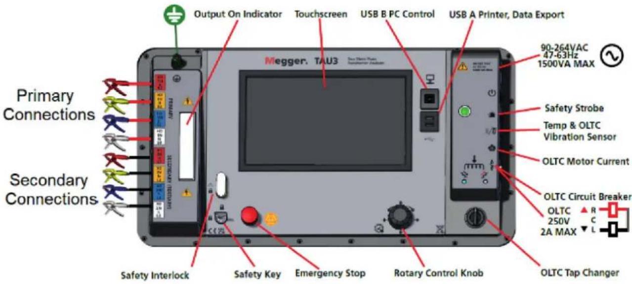

Before installing PC software, contact your IT department. Your IT department can assist with install and provide administrator approval if required.
Control of the TAU3 is possible from the built-in touchscreen or from a USB connected PC with the PC software installed. To install the PC SW:
- Locate the TAU3 PC software installer
a. From the TAU3
i. Connect the TAU3 to a PC with the included USB cable
ii. Turn on the TAU3
iii. After initialization, a CD drive will appear on the PC which contains the software
iv. Locate the file named TAU3_installer_X.xxx.exe. X.xxx is the version.
b. From the internet
i. Go to www.megger.com/TAU3
ii. Download the latest PC installer
-
Double click to launch the installer
-
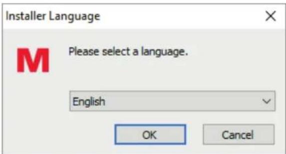
Select a language for the install and click OK.
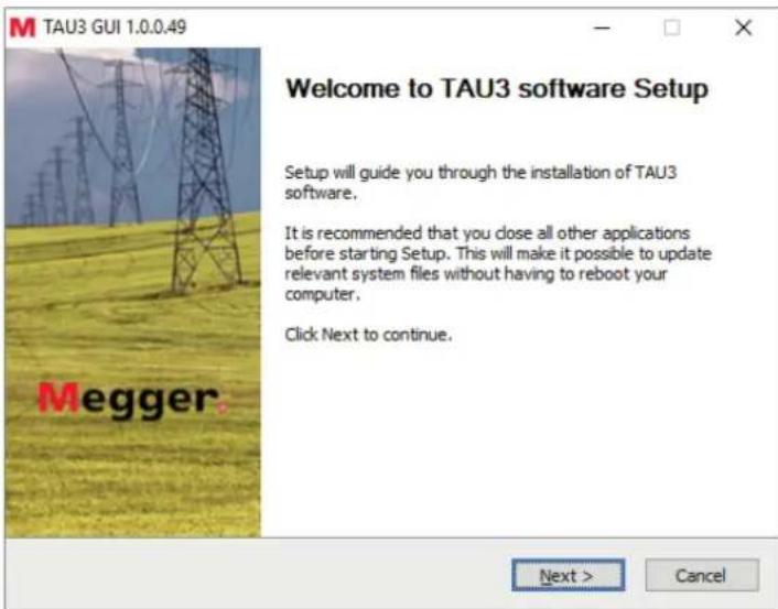
- Click Next on the welcome screen
PC software installation
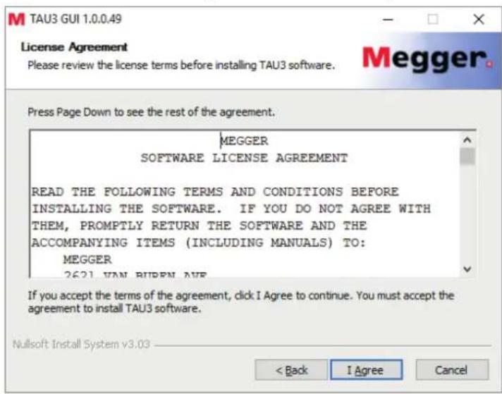
5. Review the license agreement and click I Agree
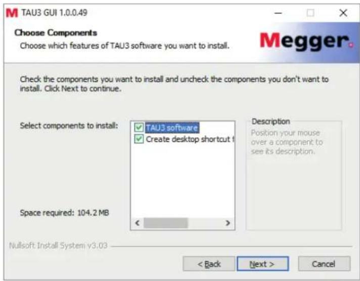
6. Choose components and select Next. Defaults recommended.
7. Select Install Location and click Install. Defaults recommended.
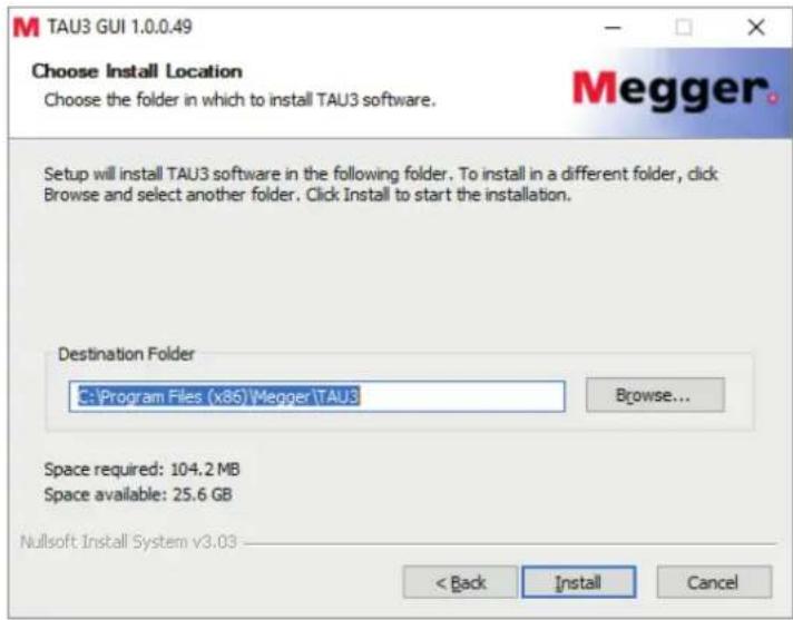
- Click Finish to complete the install.

PC software update
When updating to a new version of the TAU3 software, the installer will remove the installed version of software.
- Locate the updated TAU3 PC software installer
a. From the TAU3
i. Connect the TAU3 to a PC with the included USB cable
ii. Turn on the TAU3
iii. After initialization, a CD drive will appear on the PC which contains the software
iv. Locate the file named TAU3_installer_X.xxx.exe. X.xxx is the version.
b. From the internet
i. Go to www.megger.com/TAU3
ii. Download the latest PC installer
-
Double click to launch the installer
-
Click OK to remove the previous TAU3 version

- Click Next on the welcome screen

5. Click Next on the uninstall TAU3 software screen
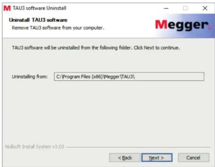
6. Click Uninstall
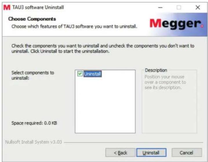
7. Click Finish
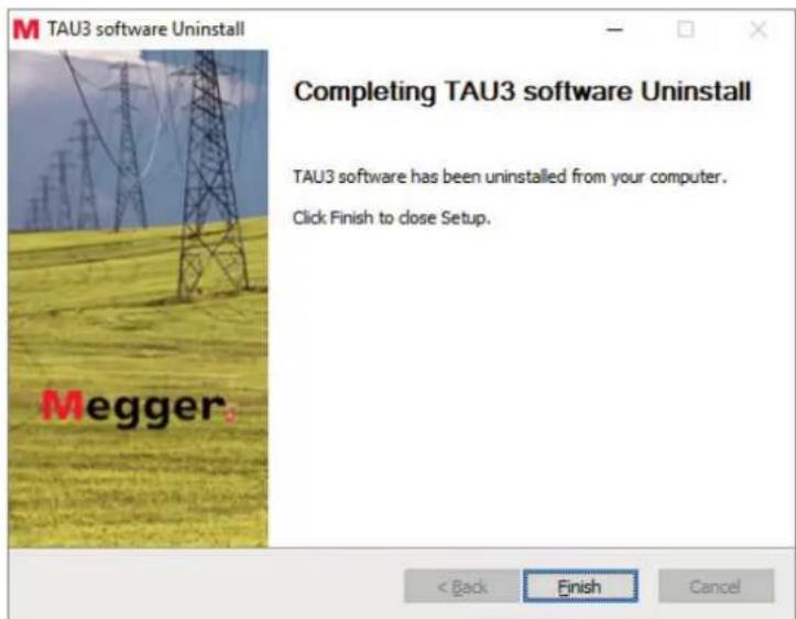
8. Proceed with the installation instructions from PC Software Installation
PowerDB installation
PowerDB Installation
PowerDB can import TAU3 data. In addition, PowerDB can control the TAU3 with the optional SW-POWERDB license. To install PowerDB, download the latest version from www.powerdb.com. Follow the instructions on screen to install PowerDB.
After turning on the TAU3, the Megger logo will display, followed by a progress screen during system initialization.
Home Screen
After the TAU3 has initialized, the display will show the home screen.
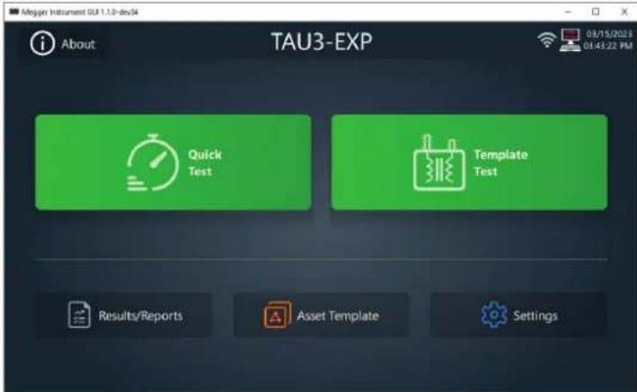
There are six options to select from the Home Screen
- About
- Settings
- Quick Test
- Results
- Asset Template
- Template Test
About
The about screen provides detailed information about the TAU3.
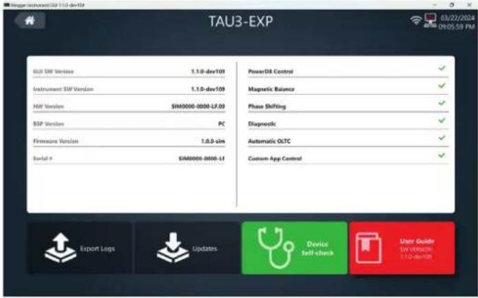
In addition, the following options are available:
- Export Logs
■ Used to provide Megger with detailed information about testing performed
- Updates
■ Used to update the TAU3 to a different software version
- Device Self-check
- Used to perform hardware verification of the TAU3
- User Guide
- Access the user guide of the TAU3
The settings screen provides options to configure the TAU3 to meet regional and testing needs
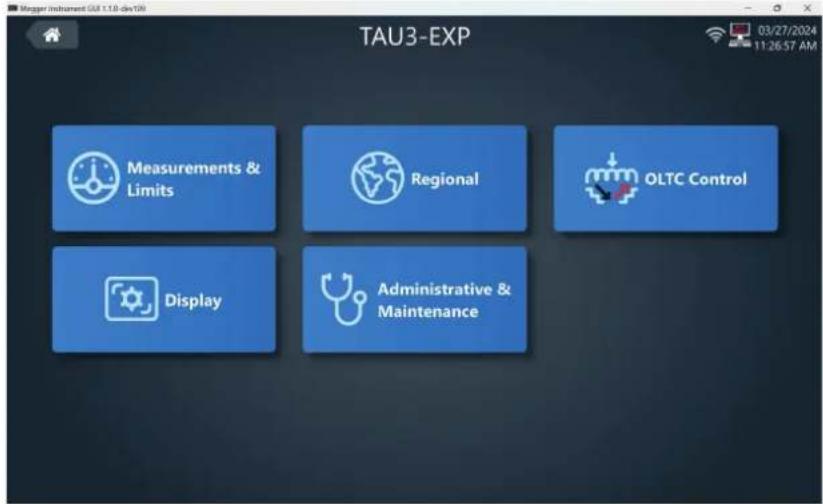
There are five options on the settings screen
- Measurement & Limits
- Configure nameplate and set limits for output and measurement verification
- Region
- Configure the TAU3 to the region it is being used
- OLTC Control
- Configure the tap changer controller for on load tap changers
- Display
■ Adjust brightness of the display
- Administrative & Maintenance
■ Perform lead calibration and restore factory settings
Measurements & Limits Settings
The measurement & limits screen is broken into ten different sections. Swiping left or right or using the left and right arrows navigate to the different setting sections.

General
General settings apply to all tests performed by the TAU3.
- Line Frequency
■ Set to 50 Hz or 60 Hz
- Test Buzzer
■ Enable or disable a countdown before each test
- Verify Connection
■ Enable or disable connection verification before each test. Disable if only one side of the transformer is connected to the TAU3
- Auto Continue
- When enabled, the TAU3 will boot to the last test performed. When disabled, the TAU3 will boot to the home screen
- One Touch OLTC
- When enabled, the One Touch OLTC option will be enabled by default when performing Template Tests that have an OLTC
- Color Rating on Results
■ Enable to emphasize measurements that exceed limits
- Show USB Thumb Drive
- Enable to display a USB Thumb Drive when connected to a PC. Disable to prevent the USB Thumb Drive from displaying
- Output Indicator Brightness
■ Change the output brightness of the warning indicator
- Export Folder
- Change the default folder where results are exported. This option is only available when controlling the TAU3 from a PC.
Configure the default nameplate used when performing tests
- Standard
- Choose from ANSI, IEC, Australian, or GOST
- Primary Vector
- Choose the default primary vector
- Secondary Vector
- Choose the default secondary vector
- Primary Tap Changer
- Choose the default primary tap changer. DETC, OLTC, or NA
- Secondary Tap Changer
- Choose the default secondary tap changer. DETC, OLTC, or NA
- Primary Tap Labels
- Choose the default primary tap labels
- Secondary Tap Labels
- Choose the default secondary tap labels
- Primary # of Taps
- Choose the default primary number of taps. If associated tap changer set to NA, this will be NA
- Secondary # of Taps
- Choose the default secondary number of taps. If associated tap changer set to NA, this will be NA
- Primary Winding Material
- Choose the default primary winding material. Copper or Aluminum. Selection will impact temperature correction for winding resistance, short circuit impedance, and efficiency tests
- Secondary Winding Material
- Choose the default secondary winding material. Copper or Aluminum. Selection will impact temperature correction for winding resistance, short circuit impedance, and efficiency tests
- Round Tap Voltages
- Choose the rounding used for tap calculations. 1 V, 5 V, or 10 V.
- Winding Temperature
- Choose the default winding temperature used for temperature correction.
- Correct winding to temperature
- Enable or disable. When enabled, winding resistance, short circuit impedance, and efficiency tests will be automatically corrected to the specified temperature.
- Auto Transformer / VReg Labels
- Choose the labels for autotransformers. Standard naming convention (ANSI, IEC, Australian, or GOST) or S,L
- Tap Phase Shift
- Choose to enable or disable tap phase shifting. Used rarely
1P Primary/secondary connections
- Choose which leads to use for 1P transformer. H1-H2/X1-X2 or H1-H0/X1-X0 options available.
Turns Ratio
■
- # OLTC Nominals
- Set the number of OLTC nominal. Used rarely.
Configure the turns ratio settings used when performing tests
- Max Test Voltage
- Set maximum induced voltage limit
■ Maximum induced voltage will be limited based on model
- Mode
- Set default test mode:
■ AUTO (recommended)
30 up
30 down
10 up
10 down
- 30 modes not available in the TAU3-BASIC
- Ratio Display
■ Select TTR (line to ground) or TNR (line to line)
- Ratio Error Limit
■ Set the turns ratio evaluation criteria. 0.5% recommended.
- Phase Deviation Display
- Set the default phase deviation display. Absolute will show total deviation of the measured phase compared to the excited phase. Relative will show total deviation of the measured phase compared to the excited phase less the expected deviation of the measured phase.
- Phase Unit
- Choose from degrees °, minutes ", or ms
- Phase Deviation Limit
■ Set the default phase deviation limit. Recommended 0.5°
Magnetic Balance
Configure the magnetic balance settings used when performing tests
- Imbalance Limit
■ Set imbalance limit. Recommended 3.0%
- Show on Quick Test
- When enabled, magnetic balance will be automatically performed with each turns ratio quick test
- Show on Template test
- When enabled, magnetic balance will be automatically performed with each turns ratio template test
- Preferred Winding
- Select which winding to perform magnetic balance. Auto recommended. When enabled, Auto mode will use YN windings for magnetic balance when present. If no YN winding, Auto mode will use the primary winding.
Configure the winding resistance settings used when performing tests
- Max Current
- Set the maximum current limit. Applies to primary and secondary windings
■ Maximum current will be limited based on model
- Stability %
- Set the stability criteria for winding resistance tests.
- Stability time
- Set the time the stability % must be maintained to indicate a measurement is stable
- Auto Save
- When enabled, results will automatically save when stability time and % criteria have bene met
- When performing winding resistance on multiple OLTC taps in template tests, Auto Save will be disabled for the first tap of each phase. After saving the first tap, the test will automatically save for the remaining taps for that phase.
- Max Winding Difference
- Set the maximum resistance difference evaluation criteria. Recommended 3.0%
- Winding Difference Calculation
- ANSI/IEC
- Diff % = ((Rmax - Rmin) / Ravg) x 100
- CEE
- Determine |Max Phase Error| from
- AVG = (Phase 1 + Phase 2 + Phase 3)
- Phase 1 Error = Phase 1 - AVG
- Phase 2 Error = Phase 2 - AVG
-
Phase 3 Error = Phase 3 - AVG
-
Diff % = (|Max Phase Error| / AVG)
* 100
- Dual Winding Excitation
- When enabled, primary and secondary will be energized and measured simultaneously
- Make Before Break
- Set current sag (10%) time limit during OLTC transitions. 5 ms recommended.
- Hard Break
- Set limit for hard break during winding resistance tests.
200 ms recommended. This setting is used to protect the operator in the event of inadvertent lead disconnection during winding resistance tests
Demagnetization
Configure the demagnetization settings used when performing tests
- Phase
■ Select a phase or all phases. Recommended B Phase
- Auto Demag After Resistance
- When enabled, the TAU3 will automatically demagnetize the transformer after a resistance test has been performed.
Efficiency
Configure the efficiency settings used when performing tests
Not available in the TAU3-BASIC
- No-load mode
- Choose between fast or full. Fast will double the eddy current losses and Full will use eddy current losses and hysteresis losses.
- Show on Quick Test
- When enabled, the efficiency test will appear when performing quick tests
- Show on Template Test
- When enabled, the efficiency test will appear when performing template tests
- Correct to Load %
- Choose the default load % used for correction of efficiency results
Short Circuit Impedance
Configure the short circuit impedance settings used when performing tests.
Not available in the TAU3-BASIC
- % Error Limit
- Set the evaluation criteria used for short circuit impedance tests. Recommended 3.0%
Impedance
- Choose the method of entering nameplate impedance, either in Z % or Z Ω.
Frequency Response Stray Losses
Configure the frequency response stray losses settings used when performing tests
Not available in the TAU3-BASIC
- Frequencies to Test
- Select the frequencies used for frequency response stray losses tests
- Show on Quick Test
- When enabled, the frequency stray losses tests will be automatically performed with each short circuit impedance tests.
- Inductance error limit
- Set the evaluation criteria used for inductance. Recommended 2.5%
- Rs error limit
- Set the evaluation criteria used for Rs. Recommended 15%
Select cancel to discard changes. Select accept to save changes.

Select back to return to the settings screen.

Select home to return to the home screen.

Select the preferred language, number format, date format, and time format for the TAU3. Date and time can be set on the TAU3. When controlled by a PC, the TAU3 will use the PC date and time.

Select cancel to discard changes. Select accept to save changes.

Select back to return to the settings screen.

Select home to return to the home screen.

OLTC Control
Select continuous press or pulse/wait operation for the on load tap changer. The majority of transformers use a pulse/wait.
When pulse/wait is selected, options for setting pulse and wait time will be displayed. Pulse is the duration required to initiate a tap change. Wait is the amount of time the tap changer requires to complete the tap changer after initiation.
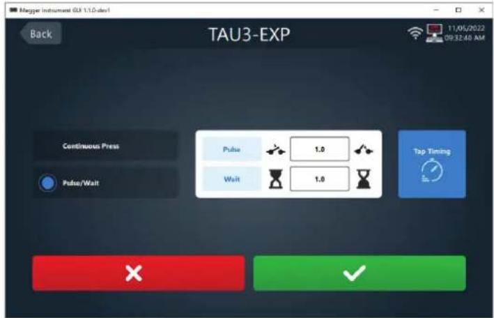
Select tap timing to use the OLTC controls on the TAU3 to set the pulse and wait time.


Select cancel to discard changes. Select accept to save changes.

Select back to return to the settings screen.

Select home to return to the home screen.

Display
Use the slider to adjust the brightness of the TAU3 display
Administrative & Maintenance
Administrative & Maintenance
After clicking on the Administrative & Maintenance setting, a password dialog box will appear. Enter the password 2621 to proceed.

Lead calibration is used for accurate impedance and efficiency test results. A one time lead calibration is typically required when using leads different than the default 9 m (30 ft) calibration. Follow testing best practices when calibrating the leads by fully uncoiling and extending leads.
Restore factory settings is used to reset the TAU3 back to the original settings from the factory. User will be prompted to confirm

Quick Test
After selecting quick test, test options will display on the left hand side of the screen. Enter a Test ID for test identification.
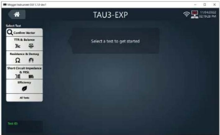
Select home to return to the home screen.

Confirm Vector
Confirm Vector
Confirm vector automatically detect the vector of the connected transformer. Recommend test settings selected by default.
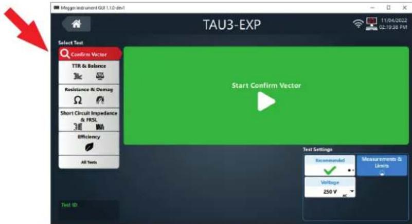
Click Start Confirm Vector to begin the test


When confirm vector completes, the vector found will be displayed. Verify the vector matches the nameplate of the transformer under test and select Accept. If the vector does not match the nameplate, select Reject.
It is the responsibility of the user to confirm that the vector matches the transformer under test. Megger accepts no responsibility for incorrectly identified vectors.
Clicking accept will select the vector found and progress quick test to TTR test setup. Clicking reject will progress to the primary vector selection screen.
Select a primary vector or autotransformer from the Primary vector select screen.

After selecting a primary vector, The secondary vector select screen will display. Select a secondary vector group and phasing. Once selected, the TTR test setup will be displayed. Select find to find the vector phasing for the selected primary and secondary group.

Vector, Phases, and Nameplate
Select TTR & Balance, Resistance & Demag, Short Circuit Impedance & FRSL, Efficiency, or All Tests to display the Select Vector, Select Phases to Test, and Select Taps to Test sections.

Select Vector and Select Phases to Test
Select Vector and Select Phases to Test
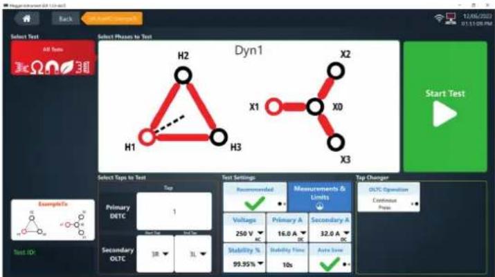
Select Primary to view the primary vector options for the transformer under test. Select Secondary to view the secondary vector options for the primary vector of the transformer under test. Select the Secondary button to change to Tertiary if testing a tertiary winding. Phase shift enables testing of phase shifting transformers. Phase shifting test capabilities not available on the TAU3-BASIC.
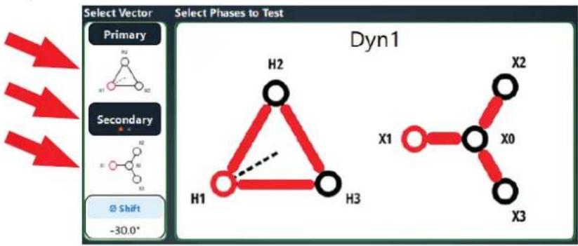
flowchart
graph TD
    A["H1"] --> B["H2"]
    B --> C["H3"]
    D["X0"] --> E["X1"]
    E --> F["X2"]
    G["X3"] --> H["X2"]
    style A fill:#fff,stroke:#000
    style B fill:#fff,stroke:#000
    style C fill:#fff,stroke:#000
    style D fill:#fff,stroke:#000
    style E fill:#fff,stroke:#000
    style F fill:#fff,stroke:#000
    style G fill:#fff,stroke:#000
    style H fill:#fff,stroke:#000
Individual phases can be enabled or disabled for testing. When testing ratio, impedance, and efficiency, in phase primary and secondary phases are tied together. For example, disabling phase A and C on the primary will disable phase A and C on the secondary.
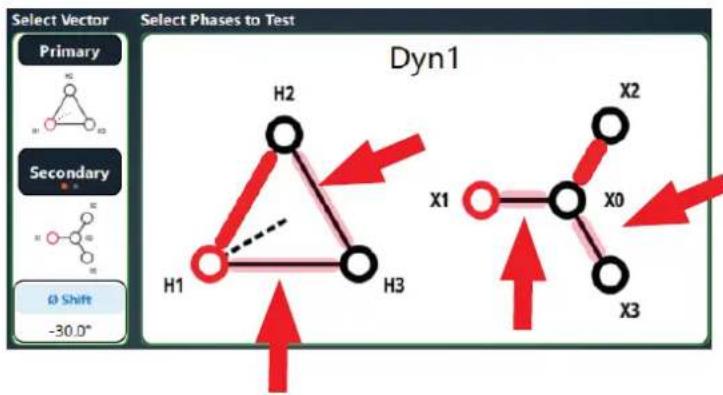
chemical
Dyne 1 molecular structure diagram showing primary and secondary states with labeled hydrogen atoms H1–H3 and X0–X3, including directional arrows indicating reaction or interaction.Nameplate
The nameplate section will populate with default settings from Measurement & Limits. Enter tap information for the transformer for evaluation against limits. Secondary can be changed to Tertiary. Base KVA can be changed to Base MVA.
Entering tap voltages for two taps of a winding will automatically calculate tap voltages for the remaining taps of the winding.
Entering L-L voltage and base KVA/MVA will calculate RATED I for the transformer.
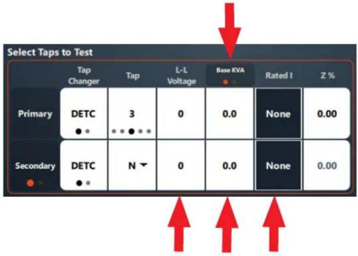
other
Select Taps to Test | Tap | Change | Tap | Voltage | Base KVA | Rated I | Z % | |---|---|---|---|---|---|---| | Primary | DETC ●● | 3 ●●●●● | 0 | 0.0 | None | 0.00 | | Secondary | DETC ●● | N ▼ | 0 | 0.0 | None | 0.00Turns Ratio & Balance
Turns Ratio & Balance
Voltage and Test Mode settings display when Turns Ratio & Balance is selected.
If Magnetic Balance is disabled in settings, only TTR will display in the Select Test section.
Select Measurement & Limits for complete settings options.

Test Mode Auto will determine the best method for testing the transformer: 3∅ or 1∅, step up or step down. Changing the test mode fill force the TAU3 to test in a specific mode, which can be useful for troubleshooting transformer problems.
Click Start Test to start the TTR & Balance test.

The TTR & Balance test in progress screen will be shown after starting the test. Test voltage and current are displayed, along with a progress bar.
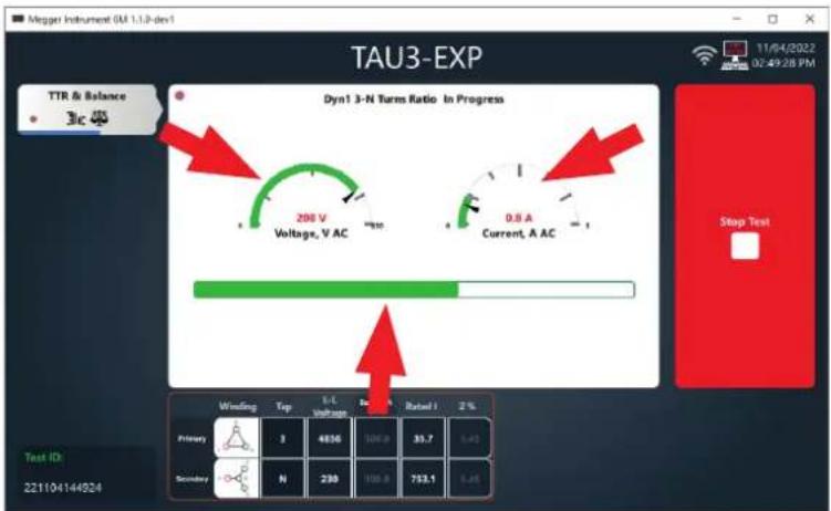
When the TTR & Balance test is complete, the following screen will display. Phases that exceed limits will be highlighted in red. Nameplate information can be edited if necessary. Ratio display, % Error, and Phase Deviation limits can be adjusted if desired.
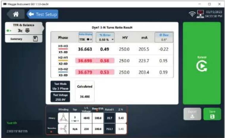
other
Dyn1 3-N Turns Ratio Result | Phase | Rate Value TTR (%) | % Error 0.50 % | HV | mA | Dev 0.5° | |---|---|---|---|---|---| | H1-H3 X1-X0 | 36.663 | 0.49 | 250.0 | 205.5 | -0.22 | | H2-H1 X2-X0 | 36.698 | 0.58 | 250.0 | 223.7 | 0.15 | | H3-H2 X3-X0 | 36.679 | 0.53 | 250.0 | 203.4 | 0.19 | | Test Mode Up 3 Phase | Calculated | | :--- | :--- | | Test Voltage 250.0V | 36.486 | | Primary | Top Rating (Hz) | L-L Rating (Hz) | Rang KVA Rating (Hz) | Rated I Z (%) | |---|---|---|---|---| | 1 | 3 | 4845 | 100.0 | 35.7 | | 2 | 1*+1** | | | | | 3 | N/A | 230 | 300.0 | 723.1 | | 4 | | | | | | 5 | | | | | | 6 | | | | | | 7 | | | | | | 8 | | | | | | 9 | | | | | | 10 | | | | | | 11 | | | | | | 12 | | | | | | 13 | | | | | | 14 | | | | | | 15 | | | | | | 16 | | | | | | 17 | | | | | | 18 | | | | | | 19 | | | | | | 20 | | | | | | 21 | | | | | | 22 | | | | | | 23 | | | | | | Total: Test ID: Z=300315168115 Test Setup: 03/15/2023 04:33:58 PM Output SaveRatio display has two options. Choose the option that is consistent with your testing practices:
- TTR, line to neutral turns ratio
- TNR, line to line turns ratio
Selecting retest will rerun the test.
If the optional 2" printer is connected, the option to print will be displayed. The results will automatically be saved after print is selected.
From the 10" display, connect a USB drive to export results. Selecting export from the PC will export to the folder designated in settings. The result will be automatically saved after exporting.
Click Save to save the result and continue with the next test.
Select TTR & Balance to change to the Balance screen.

Phases that exceed imbalance limits will be highlighted in red. Phases that exceed balance limits can be an indication that the transformer is magnetized.
Turns Ratio & Balance

bar
Dyn1 3-N Magnetic Balance Result | Phase | Value (%) | |---|---| | X1-X0 | 95.7 | | X2-X0 | 98.7 | | X3-X0 | 100 | | Total Induced LIME: 63.0% | 95.5 | | Winding Top 1-5 Voltage Gain X2A Rate/ F % | 97.6 | | Primary 3 4056 300.0 31.7 5.45 N = 230 300.0 738.1 3.43 Test ID: 2211041445524 TIR & Balance Jlc Summary 11/06/2022 02:53:22 PM StartWinding Resistance & Demagnetization
Voltage, Primary Current, Secondary Current, Stability %, Stability Time, and Auto Save settings display when Winding Resistance & Demagnetization is selected.
Select Measurement & Limits for complete settings options.
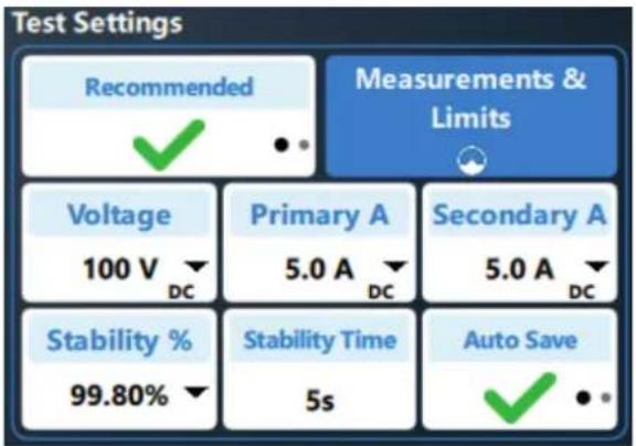
Primary test current is determined by the RATED current of the primary winding. The TAU3 will select 15% of rated current, or the maximum output of the TAU3, whichever is lower. TAU3 BASIC maximum primary current is 10 A. TAU3 ADV, PRO, and EXP maximum primary current is 16 A.
Like primary test current, secondary test current is determined by the RATED current of the secondary winding. The TAU3 will select 15% of rated current, or the maximum output of the TAU3, whichever is lower. TAU3 BASIC maximum secondary current is 10 A. TAU3 ADV maximum secondary current is 16 A. TAU3 PRO and EXP maximum secondary current 32 A.
Click Start Test to start the winding resistance test.

Click Demag to perform demagnetization
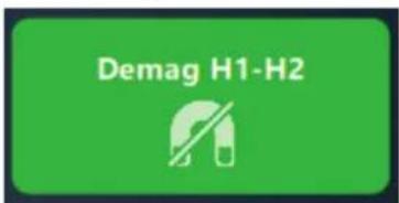
The winding resistance test in progress screen will display after clicking start test.
Phases for windings that have yet to be tested will be displayed in red (H1-H2 below)
Phases that are in progress will show an excitation symbol around the phase (H2-H3 below). Resistance values will be displayed next to phases that are in progress and will continuously update until the resistance measurement is saved.
Phases saved are displayed in black (H1-H3).
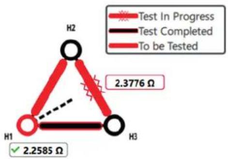
other
| Category | Value | |---|---| | Test In Progress | 2.3776 Ω | | Test Completed | 2.2585 Ω | The chart displays a triangle with three vertices labeled H1, H2, and H3. The legend indicates red symbols: 'Test In Progress', black symbol: 'Test Completed', and solid red line: 'To be Tested'. An arrow points from H1 to H2 to H3, suggesting a transition or change in the measured variable.Winding Resistance & Demagnetization
Resistance, current, stability %, and stability time will be displayed for each winding. When the stability % exceeds the set limit, a timer will start. When the timer exceeds the setting for both windings, the Save button will turn green. If Autosave is enabled, the result will automatically save, and the next phase will be tested. If no more phases remain to be tested, the winding resistance test will finish by discharging the transformer. Discharge is indicated by orange/red lights of the output indicator.
Do not disconnect the leads from the transformer or TAU3 during discharge. In the event of power loss during winding resistance tests or discharge, the TAU3 will continue to discharge the transformer passively, indicated by red LEDs on the output indicator. When discharge is complete, the LEDs will turn off, and the leads can be removed.

If Auto Demag after Resistance is enabled, or if Demag is selected from the Resistance & Demagnetization screen is clicked, the Demag in progress screen will be displayed.
Demag is performed by applying +DC voltage and measuring the time it takes for the transformer core to begin saturation. Polarity is then reversed, and time is measured until saturation occurs in the opposite direction. Based on these initial tests, +DC and -DC voltage is applied in decreasing time intervals until the transformer is demagnetized.
![Megger Instrument GB(1.1.0 dev) Test [221104144924 - Resistance] was complete successful! Accept 11/04/2022 03:31:29 PM Resistance & Demag Dyn1 3-N Demagnetization Result In Progress Phase Extraction H1-H2 50 V Voltage V DC Current A DC Winding Tap L-A voltage New EVA Rated I 2 % Primary 3 4856 106.0 $5.7 5.49 Secondary N 238 100.1 733.1 5.49 Stop Test Test ID: 221104144924](/content/2026/05/943199/images/15e46feabc4c348022298e05113447d34ecef44d7d9e1d15288973c5f6f7ea02.jpg)
When the winding resistance test is complete, the following screen will be displayed. Phases that exceed limits will be highlighted in red. The software will recommend to retest these individual phases.
Corrections to a set temperature can be enabled or disabled. Ensure that winding temperature and primary and secondary winding material are set correctly for accurate temperature correction.
Winding Resistance & Demagnetization

Selecting Resistance & Demag will display the demagnetization graph
The phase that was demagnetized, along with before and after remanence and demag time will be displayed.

line
| Phase | Before | After | Time | |-------|--------|-------|------| | H1-H2 | 21.29% | 3.20% | 0.0s | | | | | | | | | | | | | | | | | | | | | | | | | | | | | | | | | | | | | | | | | | | | | | | | | | | | | | | | | | | | |Short Circuit Impedance
Short Circuit Impedance / Leakage Reactance and Frequency Response Stray Losses
Shorting options will be displayed when Short Circuit Impedance / Leakage Reactance and Frequency Response Stray Losses is selected. Test Current cannot be changed.
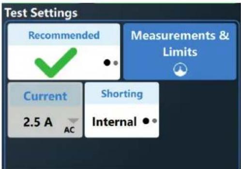
When shorting is set to external, an option to display a shorting diagram will be displayed

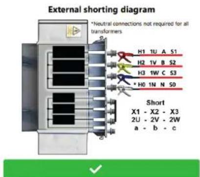
The Short Circuit Impedance & FRSL test in progress screen will be shown after starting the test. Test voltage and current are displayed, along with a progress bar.

When Short Circuit Impedance & FRSL test is complete, phases that exceed limits will be highlighted in red.
Winding temperature and temperature correction can be adjusted if necessary. Refer to the transformer nameplate to determine the temperature rise of the transformer and add this value to 20° C.
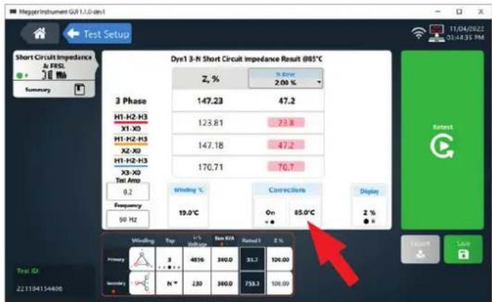
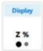
Clicking on Display will show detailed impedance test information.

other
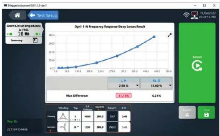
Dynl J-N Short Circuit Impedance Result @81°C | Phase | Z, Ω | Xs, Ω | L, H | PF, % | Rs, Ω | |---|---|---|---|---|---| | 3 Phase | 231.46 | 226.19 | 0.60000 | 21.382 | 48.662 | | H1-H2-H3 | 194.64 | 188.50 | 0.50000 | 24.929 | 48.523 | | X1-X0 | 231.37 | 226.19 | 0.60000 | 21.032 | 48.662 | | H1-H2-H3 X2-X0 | 268.37 | 263.89 | 0.70000 | 18.184 | 48.800 | | H1-H2-H3 X3-X0 Test Amp. | 6.2 | - | - | - | - | | Frequency 60 Hz | 19.0°C | - | - | - | - | | Rotation (On) | - | - | - | 85.0°C | - | | Display (ZΩ) | - | - | - | - | - | | Wiring: Top L-L Voltage: Gain (V) Rated: R/L % Primary: 3 4854 300.0 15.7 100.00 Secondary: N 230 304.0 751.1 100.00 Test ID: Z21104134496Clicking on Short Circuit Impedance & FRSL will change to FRSL display

Inductance or Rs limits that exceed limits will be highlighted in red.
line
| Time | Value | |------|-------| | 0.0 | 41.7 | | 15.0 | 41.7 | | 163.4| 41.7 | | 185.0| 41.7 | | 225.6| 41.7 | | 275.0| 41.7 | | 316.0| 41.7 | | 386.0| 41.7 | | 443.6| 41.7 | | 496.0| 41.7 | | 150.0| 41.7 |Efficiency
Efficiency
No settings are available for efficiency tests. Click Start Test to begin efficiency tests. The efficiency test in progress screen will be shown after starting the test. Test voltage and current will be displayed, along with a progress bar.

When the efficiency test completes, the following screen will be displayed.
Primary winding material, secondary winding material, winding temperature, and correction to winding temperature and load % can be adjusted.

All Tests
When selecting all tests, the following options will display.
Select Measurement & Limits for complete settings options.
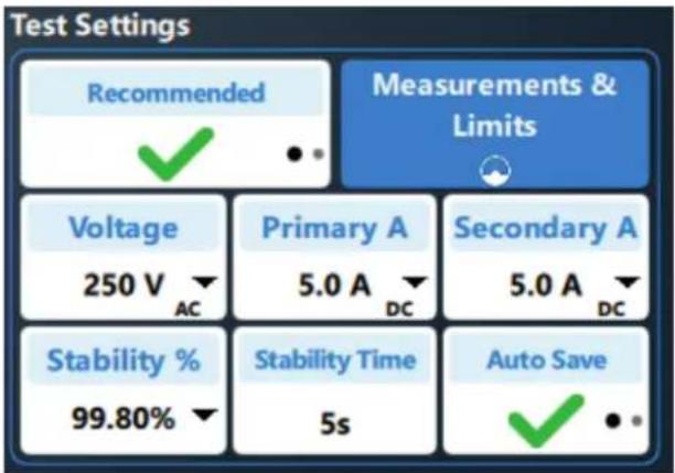
Depending on the TAU3 model, software features enabled, and tests enabled in settings, clicking start test will progress through tests in the following order:
- Turns Ratio
- Magnetic Balance
- Winding Resistance
- Demagnetization
- Short Circuit Impedance
- Frequency Response Stray Losses
- Efficiency
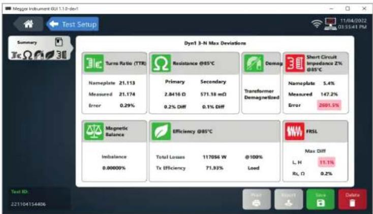
When testing is complete, a report card for the completed tests will be displayed.
Tests that exceed limits will be highlighted in red if color coded results are enabled..
Clicking on a test card will take the software to the phase by phase results for the test selected.
Save, Print, Export, Retest, Home, Test Setup
Save, Print, Export, Retest, Home, Quick Test Setup
Quick test results are automatically saved at the end of the test. If the namplate or test results settings are changed, a save button will appear. Click save to update the results with the new setting and return to the test setup screen.
Print will print to the optional 2" printer. Print will only display when the printer is detected
Export will export results to a USB thumb drive. Export will only display when a thumb drive is detected, or when operating the TAU3 from a USB connected PC.
After completing a test, an option to retest will be displayed.


Select test setup to return to the quick test setup screen.

Select home to return to the home screen.

Results
After saving, results will be available for review in the results screen. Results can be sorted by asset ID, vector, test ID, Date, tests performed, and # of results. In addition, results can be filtered by Asset ID.
Tests Performed will show icons for the tests saved for the test ID. TTR, Magnetic Balance, Resistance, Short Circuit Impedance, and Frequency Response Stray Losses icons in green indicate results that are within limits. A demag symbol in green indicates a successful demagnetization of the transformer. Icons in red indicate results that are not within limits.
Select a result to view the test information. Selecting a check box will enable delete, export, and test options
Select multiple check boxes to delete or export multiple results
Select the check box in the table header row to select all results.

After selecting a result, the test information will be displayed.
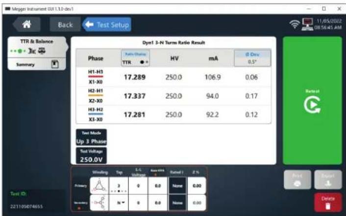
Select delete to delete the results. Confirmation is required to delete the result

Results

Delete result?
Delete selected results in 221105074655 at taps: 3 - N?


Asset Template
Enter an Asset ID for identification of the asset.
Select Primary and Secondary vector and enter line to line voltage, KVA/MVA, and Z % for the transformer.
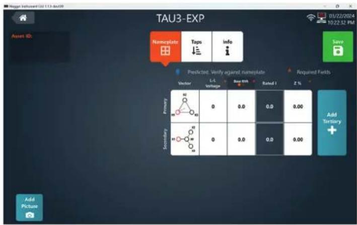
Select add tertiary if the transformer has a tertiary winding.

Select save to save the asset template

Select add picture to add pictures to the asset template.

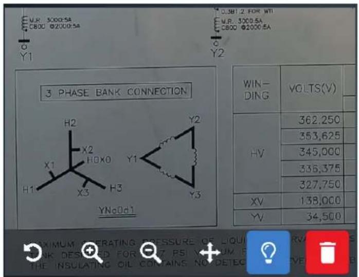
Asset Template
Use the rotate, zoom in, and zoom out buttons to view picture details. Click and hold to move the picture around. Pinch to zoom and swipe to view picture details on the TAU3 display.

natural_image
Three white magnifying glass icons on a dark background: refresh, add, and minus sign (no text or symbols)Delete will remove the picture from the asset template

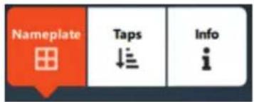
When asset template is first selected, nameplate entry will selected.
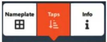
Select taps to configure the tap changers for the primary and secondary winding. Winding options will be prepopulated based on measurement & limits settings.

After entering two tap voltages, the remaining tap voltages will automatically calculate. Override tap voltages as required. Select reset tap voltages to clear tap voltages.

Select Info to enter additional common nameplate information.
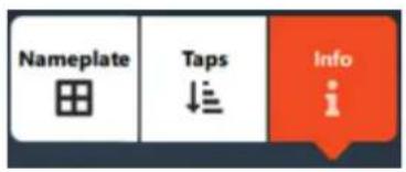

- Manufacturer
- Serial Number
- Year
- Substation
- Position
- Tank Type
- Primary BIL
- Secondary BIL
- Class
- Coolant
- Core Design
- Weight
- Primary winding material
- Secondary winding material
Select add custom field to enter custom nameplate information.

Custom Field
Template Test
Template Test
Asset templates can be sorted by Asset ID, vector, primary voltage, secondary voltage, KVA, and last test date and time. Select an Asset ID to proceed to the template test screen.

Select add to create a new asset template

Select export all to export all asset templates

Select import to import exported asset ids.

Select the check mark next to an asset id to show additional options.

Select test to go to the template test screen
Select edit to edit the asset template

Select export to export the asset template

Select copy to copy the asset template

Select delete to delete the asset template

The template test screen is similar to quick test. Select a test to get started.

Select edit to edit the asset template.

Enter a Test ID for the asset template test. Useful for grouping asset test results for specific testing activities or for tests performed on different days.
Template Test

After selecting a test, taps to test and test settings will display. Tap selections available based on asset template configuration. Specific test settings will be displayed based on the test selected, same as quick test.
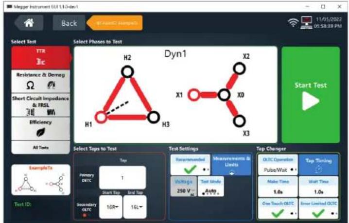
If the asset has an OLTC, there will be options for configuring OLTC control

Single Tap Test

If the asset does not have an OLTC, or the start and end tap for the OLTC are the same, testing will be complete as described in quick test.
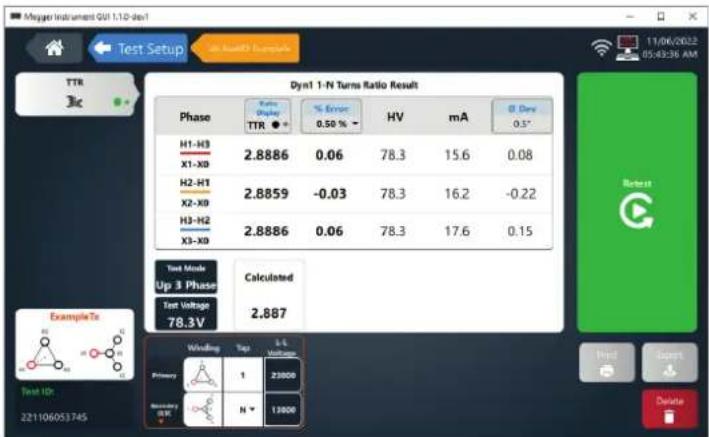
other
Dyn1 1-N Turns Ratio Result | Phase | Ratio (Value) TTR ●-1 | % Error 0.50 % - | HV | mA | θ Dev 0.5° | |---|---|---|---|---|---| | H1-H3 X1-X0 | 2.8886 | 0.06 | 78.3 | 15.6 | 0.08 | | H2-H1 X2-X0 | 2.8859 | -0.03 | 78.3 | 16.2 | -0.22 | | H3-H2 X3-X0 | 2.8886 | 0.06 | 78.3 | 17.6 | 0.15 | Text Mode Up 3 Phase Test Voltage 78.3V Calculated Windling Top 1-4 Voltage Primary 1 23000 Secondary HV N 12000 Test ID: 221106053745 11/06/2022 05:43:36 AM Reset Next > DeleteWhen testing is complete, the Test Setup button can be used to return to the Template Test setup screen.

In addition, the tap can be changed in the nameplate section to test other tap positions.
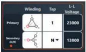
other
| Category | Winding | Tap | L-L Voltage | |---|---|---|---| | Primary | [IMAGE] | 1 | 23000 | | Secondary OLIC | [IMAGE] | N ▼ | 13800 |Below is an example when the tap is changed and no results are available.

Click Start Test

Multiple Tap OLTC AC Tests
Multiple Tap OLTC AC Tests - TTR, Magnetic Balance, Short Circuit Impedance, FRSL, and Efficiency
The start tap and end tap of an OLTC can be changed to test multiple tap positions.
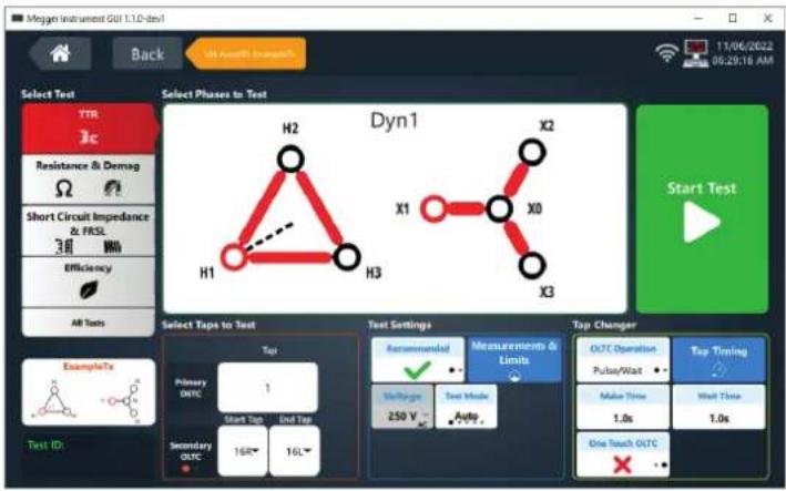
The screen below is displayed after a test is complete when testing TTR & Balance, Short Circuit Impedance & FRSL, or Efficiency.
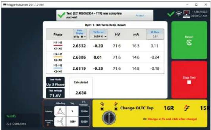
If the TAU3 tap changer cable is connected to the TAU3 and to the transformer OLTC control, the TAU3 OLTC switch can be used to change the tap changer position. If set to Continuous Press, the next test will begin when the TAU3 OLTC switch is released. If set to pulse/wait, the next test will begin when the pulse/wait timing is complete.
Note: If the tap changer is operated in the opposite direction as indicated in the software, testing will continue in the new direction selected.
If the TAU3 OLTC is not used, the OLTC must be changed manually at the transformer. When the tap change is complete, click the yellow button to begin the next test.
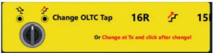
Testing will complete when the last tap is tested.
Multiple Tap OLTC Winding Resistance Tests
The start tap and end tap of an OLTC can be changed to test multiple tap positions.

The screen below is displayed after the first phase and tap are complete when testing winding resistance.

If the TAU3 tap changer cable is connected to the TAU3 and to the transformer OLTC control, the TAU3 OLTC switch can be used to change the tap changer position. If set to Continuous Press, the next test will begin when the TAU3 OLTC switch is released. If set to pulse/wait, the next test will begin when the pulse/wait timing is complete.
Note: If the tap changer is operated in the opposite direction as indicated in the software, testing will continue in the new direction selected.
If the TAU3 OLTC is not used, the OLTC must be changed manually at the transformer. When the tap change is complete, click the yellow button to begin the next test.
Multiple Tap OLTC Winding Resistance Tests

When the last tap of the first phase is completed, the test set will automatically discharge and energize the next phase to be tested.
Testing will complete when the last tap of the final phase has been saved.
Multiple Tap OLTC All Tests
The start tap and end tap of an OLTC can be changed to test multiple tap positions.
When performing All Tests, the procedure is as follows.
- Preliminary Demagnetization.
- Used to ensure accuracy of AC tests. Can be canceled.
- Tap Changer Verification.
- When Auto OLTC is selected, the TAU3 will automatically confirm proper connection to the tap changer by performing a series of TTR tests and tap changes. Can be canceled.
-
TR & Balance*, Short Circuit Impedance & FRSL*, and Efficiency* will be tested on each tap from start tap to end tap
-
Winding resistance
a. Phase A end tap to start tap
b. Phase B start tap to end tap
c. Phase C end tap to start tap
- Demagnetization
*Balance, FRSL, and efficiency will only be tested if purchased and enabled.
PowerDB Import
PowerDB Import
The combined 30 form can be used to import TAU3 data into PowerDB.
PowerDB Control
The combined 30 form can be used to configure and run tests with the TAU3.
Service
If immediate assistance is required, please contact the customer service by telephone or email:
+1 670 676 8500
vfcustomersupport@megger.com
Troubleshooting
The Troubleshooting Guide is designed to evaluate the reasons for a TAU3 malfunction. The possible test set malfunctions and causes are listed below. Electronic circuit repairs should not be attempted in the field. Refer to Repair section.
TTRU3 does not turn on
- Check that the power cord is fully inserted into the TTRU3.
- Check that the power source is outputting voltage at acceptable levels and frequency.
- Check that the power cord is fully inserted into the source.
- Check that the power switch is in the correct position (1).
■ Set the power switch to off (O)
Wait 30 seconds
Set the power switch to on (1)
■ Try another power cord
Lead check
■ Connect the leads as described below
H1 to X1
H2 to X2
H3 to X3
H0 to X0
■ Select Dd0, Yy0, or YNyn0 and perform a test
■ Verify ratio between 1.0005 and 0.9995
TTRU3 Reports test failed, but still provides data
- Check lead connections. Reference Nameplate to ensure leads are connected to the correct bushing.
Printer not working
- Check battery is inserted into printer
- Charge printer battery using supplied charger
- Check printer paper is inserted properly
- Check USB cable is plugged into printer
- Check USB cable is plugged into TTRU3 USB port
- Check printer is turned on by holding power button
■ Try other USB ports
Maintenance
OLTC moving in wrong direction
- Check the OLTC wiring diagram and ensure leads are connected to correct terminals.
Cannot connect TTRU3 to PC
Contact your IT department for primary assistance when connecting any device to your PC.
- Check USB cable is fully inserted into the TTRU3
- Check USB cable is fully inserted into PC
- Check the TTRU3 is powered on
- Check TTRU3 SW is installed
- Check TTRU3 is running
■ Move USB cable to another USB port on your PC
■ Try another USB Cable
Try another PC
Maintenance
Only qualified persons familiar with the hazards involved with high-voltage test equipment should perform maintenance. Read and understand Sections 1, 2, 3, 4, and 5 before performing any service.
The TTRU3 requires only periodic inspection. Inspect all hardware items to ensure all are in good condition.
The TTRU3 may be cleaned periodically. In so doing, do not allow water to penetrate panel holes. An all-purpose, household spray cleaner can be used to clean the panel. Polish with a soft, dry cloth. Clean the cables and mating panel receptacles with isopropyl or denatured alcohol applied with a clean cloth.
Calibration
A complete performance and calibration check should be made at least once every year. This will ensure that the TTRU3 is functioning properly over the entire measurement range. The TTRU3 calibration is performed on each new or repaired unit before sending it to a customer.
Repairs
Any service or repair of this equipment should be performed only by qualified persons who are aware of electrical hazards and the necessary precautions required to prevent injury.
Megger offers a complete Repair and Calibration Service and recommends that its customers take advantage of this service for routine maintenance or in the event of any equipment malfunction.
In the event Service is required, contact your Megger representative for a product Return Authorization (RA) number and shipping instructions.
Ship the product prepaid and insured and marked for the attention of the Megger Repair Department. Please indicate all pertinent information, including catalog number, serial number, and problem symptoms.
Manufacturing sites
Megger Limited
Archcliffe Road
Dover
Kent
CT17 9EN
ENGLAND
T.+44 (0)1 304 502101
F. +44 (0)1 304 207342
Megger GmbH
Weststraße 59
52074
Aachen
Germany
T.+49 (0) 241 91380 500
E. info@megger.de
Megger Valley Forge
400 Opportunity Way
Phoenixville
PPA 19460
USA
T. 1-610 676 8500
F. 1-610-676-8610
Megger USA - Dallas
4545 West Davis Street
Dallas
75211-3422
T.+1 214 333 3201
F. +1 214 331 7399
USsales@megger.com
Megger AB
The company reserves the right to change the specification or design without prior notice.
Megger is a registered trademark
The Bluetooth ® word mark and logos are registered trademarks owned by Bluetooth SIG, Inc and is used under licence.
Part No: TAU3_UG_en_V01g
- Notice
- WARRANTY
- Contents
- Table of Contents
- Quick Test....37
- Results ....53
- Asset Template 55
- Template Test ....58
- PowerDB Import 66
- Service 67
- Maintenance 68
- Introduction
- Purpose of this manual
- Audience
- Item received
- Optional software accessories
- Optional hardware accessories
- ORDERING INFORMATION
- Item (Qty) Cat. No.
- TAU3 BASIC and ADV lead sets
- Optional Lead Accessories
- TAU3 BASIC and ADV 16 A H and 16 A X lead extensions
- Included accessories - EXP
- Included accessories - PRO
- TAU3 PRO and EXP lead sets
- TAU3 PRO and TAU3 EXP 16 A H and 32 A X lead extensions
- Warnings and safety precautions
- WARNING!
- Safety Precautions
- CAUTION!
- GENERAL SAFETY PRECAUTIONS
- SAFETY IS THE RESPONSIBILITY OF THE USER
- Max Technical Specifications
- Specifications - Valid from -20 ° to +50 °C
- Input power
- Output power
- Regulatory
- Case
- Internal/external data storage
- Communication/control software
- Touch screen (optional)
- Printer (optional)
- Environmental
- TTR
- Excitation current resolution
- Excitation current accuracy
- Technical specifications
- WR
- Resistance measurement methods
- DC Open circuit voltage
- DC Measurement voltage
- Current and resistance ranges
- Dynamic resistance measurement method
- Dynamic Resistance Speed
- SCI FRSL
- Impedance measurement methods
- Impedance measurement range
- Reactance measurement
- Power factor accuracy
- Efficiency
- Connections and controls
- PC software installation
- Review the license agreement and click I Agree
- Choose components and select Next. Defaults recommended.
- Select Install Location and click Install. Defaults recommended.
- PC software update
- Click Next on the uninstall TAU3 software screen
- Click Uninstall
- Click Finish
- Proceed with the installation instructions from PC Software Installation
- PowerDB installation
- Home Screen
- About
- Measurements & Limits Settings
- General
- Turns Ratio
- Magnetic Balance
- Demagnetization
- Short Circuit Impedance
- Frequency Response Stray Losses
- OLTC Control
- Display
- Administrative & Maintenance
- Quick Test
- Confirm Vector
- It is the responsibility of the user to confirm that the vector matches the transformer under test. Megger accepts no responsibility for incorrectly identified vectors.
- Vector, Phases, and Nameplate
- Select Vector and Select Phases to Test
- Nameplate
- Turns Ratio & Balance
- Winding Resistance & Demagnetization
- Short Circuit Impedance / Leakage Reactance and Frequency Response Stray Losses
- All Tests
- Save, Print, Export, Retest, Home, Test Setup
- Save, Print, Export, Retest, Home, Quick Test Setup
- Results
- Delete result?
- Asset Template
- Template Test
- Single Tap Test
- Multiple Tap OLTC AC Tests
- Multiple Tap OLTC AC Tests - TTR, Magnetic Balance, Short Circuit Impedance, FRSL, and Efficiency
- Multiple Tap OLTC Winding Resistance Tests
- Multiple Tap OLTC All Tests
- PowerDB Import
- PowerDB Control
- Service
- Troubleshooting
- TTRU3 does not turn on
- Lead check
- TTRU3 Reports test failed, but still provides data
- Printer not working
- Maintenance
- Calibration
- Repairs
- Manufacturing sites
Brand : Megger
Model : TAU3
Category : Measuring instrument