MATRIX-1616-C - Router DVDO - Free user manual and instructions
Find the device manual for free MATRIX-1616-C DVDO in PDF.


| Product Type | Modular Seamless Matrix Router |
| Model | MATRIX-1616-C |
| Dimensions (W x D x H) | 483 x 365 x 178 mm (4U) |
| Gross Weight | 13 kg |
| Power Supply | 200W x 2 (Redundant), AC 100-240V, 50/60Hz |
| Input/Output Capacity | Up to 16 inputs and 16 outputs |
| Control Interfaces | RS-232 (9600 baud), Ethernet/LAN (TCP/IP), Web GUI, PC Software |
| Video Resolutions (2K Cards) | Up to 1920x1080@60Hz |
| Video Resolutions (4K Cards) | Up to 3840x2160@60Hz |
| Switching Technology | Seamless switching with <1ms transition |
| Video Wall Support | Gen-lock based, delay <0.1ms between outputs, up to 80x80 |
| On-Screen Display (OSD) | Customizable font, color, size, position, background (2K cards only) |
| Operating Temperature | 0°C to 40°C |
| Storage Temperature | -20°C to 60°C |
| Humidity | 20% to 90% RH (non-condensing) |
| Expansion Cards Supported | DVI-U, HDMI, VGA, SDI, HDBaseT, Fiber (2K/4K) |
| Repairability | Modular design; input/output boards field-replaceable |
Frequently Asked Questions - MATRIX-1616-C DVDO
User questions about MATRIX-1616-C DVDO
0 question about this device. Answer the ones you know or ask your own.
Ask a new question about this device
Download the instructions for your Router in PDF format for free! Find your manual MATRIX-1616-C - DVDO and take your electronic device back in hand. On this page are published all the documents necessary for the use of your device. MATRIX-1616-C by DVDO.
USER MANUAL MATRIX-1616-C DVDO
natural_image
Illustration of five black server racks arranged in ascending order, with green indicator lights on the front panel (no text or symbols visible)Modular Seamless Matrix
DVDO-Matrix-88-C 8x8
DVDO-Matrix-1616-C 16x16
DVDO-Matrix-3636-C 36x36
DVDO-Matrix-8080-C 80x80
User Manual
Version: V1.1.0
CE


Table of Contents
1. Modular Seamless Matrix System .... 1
1.1. Product profile.... 1
1.2. Product performance .... 3
1.3. Specification & Parameters (Matrix, DVI-U as example) 3
1.4. Specification & Parameters (2K seamless cards) 4
1.5. Specification & Parameters (4K seamless cards) 4
2. Modular Matrix rear terminal view (8x8, DVI-U board for example) 4
3. Modular Matrixperipheral device connection (8x8 for example) 5
3.1. Input and output 5
3.2. Communication port and connection method....5
3.2.1. RS232 control and connection....5
3.2.2. Ethernet control and connection....5
3.2.3. Front panel 6
4. Modular Matrix PC tool user guide (8x8 for example) 7
4.1. UART Control 7
4.2. Network Control: 8
4.2.1. Direct connection via Ethernet cable 8
4.2.2. Connection via LAN 10
4.2.3. Configure the network module of the device 10
4.2.4. Troubleshoot....12
4.3. Matrix Switch: 13
4.4. Signal Setting 14
4.5. Fine Tune: PQ&Position 15
4.6.OSD CTRL: 16
Select the output port that you want to control....17
Turn ON/OFF the OSD....17
Set the background transparent or not....17
Set the alpha of the OSD 17
Set the text color or the background color.... 18
Set OSD Width and Height....18
Set the OSD position....19
Set the text font type and font size. 19
Set the OSD content: 19
4.7. TV Wall: 20
4.8. EDID control: 22
5.Modular Matrix Control via Web: 23
6. Modular Matrix Using Cautions....24
1. Modular Seamless Matrix System
1.1. Product profile
- Modular multi-format mixed seamless switching matrix is a high-performance video signal switching equipment. It supports up to 8\~80 inputs, 8\~80 outputs with many kinds of daughter cards. This product supports multiple video formats input and output.
- Multi-format matrix using the daughter cards structure, flexible and convenient installation. The input/output port support: Fiber, HDBaseT, SDI, HDMI, VGA, DVI-U(HDMI/DVI/VGA/YPbPr/CVBS).
- With the Ethernet/LAN and RS232 communication interface, through the PC software to control the matrix signal switching, monitoring the working status of the matrix, set the signal resolution, etc..
Highlights 1: Seamless Switching
| Normal Switching Seamless Switching | |
Current video: | Current video: |
| After change source, new video need around 3~10s | After change source, new video comes out in a few ms. |
New video: | New video: |
Highlights 2: Gen-lock based Video Wall
Based on Gen-Lock technology, the video delay between any output channel is less than 0.1ms, the video will not distorted.
Available in 8x8\~80x80 depends on number of output channels.
It's especially matched with LCD/LED Video Wall
| Distorted (2x2) There is 100ms~200ms delay between different output channels. | Gen-Locked (2x2) Based on Gen-Lock, the delay is <0.1ms. | ||
Highlights 3: Any kind of Font
Default: English, Chinese
Available: French, German, Hindi, Portuguese and Spanish, etc.
Size/Color/Position/Content may be set by PC/Notebook.

1.2. Product performance
● Redundant power supply
● Support Seamless switching
● Support up to 8\~80 inputs and 8\~80 outputs
● Input/Output port: Fiber, HDBaseT, 3G-SDI, HDMI, DVI-U(HDMI/DVI/VGA/YPbPr/CVBS)
● maximum resolution of 1920 x 1080@60Hz (2K cards); 3840x2160@60Hz(4K cards)
● Control interface: RS232, Web-based Ethernet/LAN
● PC software to facilitate remote control, real-time display the input and output status
- Scalar inside, output resolution control available
- Video wall function
● Character overlay function: Font / color / size control available
1.3. Specification & Parameters (Matrix, DVI-U as example)
| 8x8, 2U | 16x16, 4U | 36x36, 8U | 80x80, 16U | |
| Front-View |  | 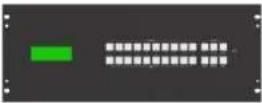 | 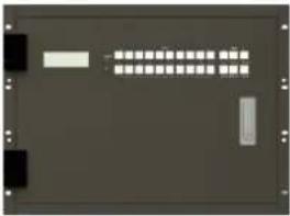 | 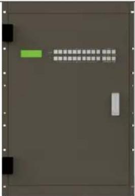 |
| Rear-View | 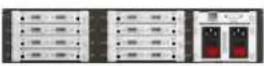 | 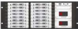 | 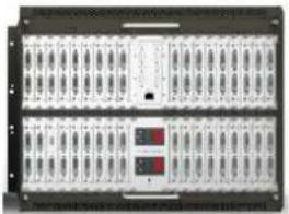 | 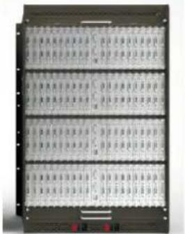 |
| Dimension W*D*H | 483x365x89mm | 483x365x178mm | 483x365x356mm | 483x365x712mm |
| Gross weight | 9Kg | 13Kg | 23Kg | 44Kg |
| Power Supply | 100W * 2 (Redundant) | 200W * 2(Redundant) | 350W * 2(Redundant) | 350W * 4(Redundant) |
| Control -RS232 | RS-232 Straight | D-sub 9 | Baud rate: 9600 |
| Control -LAN | Static IP, Automatic IP | ||
| Power supply AC100 - 240V | 50/60Hz | ||
| Working temperature 32 - 104°F / 0 - 40°C | |||
| Storage temperature -4 - 140°F / -20 - 60°C | |||
| Humidity | 20 - 90% RH (no condensation) | ||
1.4. Specification & Parameters (2K seamless cards)
| Input | Interface type | Signal | Format |
| DVI-U | HDMI | HDMI / DVI / VGA: | |
| DVI | 800x600,1024x768,1280x768,1280x800,1280x1024,1360x768,1400x1050,1600x1200,192 | ||
| VGA | 0x1080 | ||
| YPbPr | YPbPr: 576i50,720p50,720p60,1080i50,1080i60, 1080p50,1080p60 | ||
| CVBS | CVBS: PAL, NTSC | ||
| HDMI | HDMI | Same as DVI-U (HDMI input) | |
| VGA | VGA | Same as DVI-U (VGA input) | |
| BNC | SDI | 480i60,576i50,1080i60,1080i50,720p60,720p50,1080p24/25/30/50/60 | |
| RJ45 | HDBaseT | Same as DVI-U (HDMI input) | |
| LC | Fiber | Single mode single Fiber, 1920x1080, up to 1.4Km or 20Km | |
| Output | Interface type | Signal | Format |
| DVI-U | HDMI | HDMI / DVI / VGA: | |
| DVI | 1024x768, 1280x1024, 1360x768, 1280x720, 1600x1200 ,1680x1050, 1920x1080 | ||
| VGA | YPbPr: 1080p60, 720p60 | ||
| YPbPr | CVBS: PAL, NTSC | ||
| CVBS | |||
| HDMI | HDMI | Same as DVI-U (HDMI output) | |
| VGA | VGA | Same as DVI-U (VGA output) | |
| BNC | SDI | 576i50,480i59,720p50,720p60,1080i50,1080i59,1080i60,1080p24/25/29/30/50/60 | |
| RJ45 | HDBaseT | Same as DVI-U (HDMI output) | |
| LC | Fiber | Single mode single Fiber, 1920x1080, up to 1.4Km or 20Km |
1.5. Specification & Parameters (4K seamless cards)
| Input | Interface type | Signal | Format |
| HDMI | HDMI | Up to HDMI 2.0 4K 444@60Hz | |
| RJ45 | HDBaseT | 4K@60Hz, works with HDBaseT seamless transmitter box. | |
| LC | Fiber | 4K@60Hz, works with Fiber seamless transmitter box. | |
| Output | Interface type | Signal | Format |
| HDMI | HDMI | Up to HDMI 2.0 4K 444@60Hz | |
| RJ45 | HDBaseT | 4K@60Hz, works with HDBaseT seamless receiver box. | |
| LC | Fiber | 4K@60Hz, works with Fiber seamless receiver box. |
Note1: OSD function is not available on 4K cards.
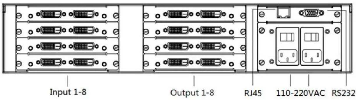
2. Modular Matrix rear terminal view (8x8, DVI-U board for example)
3. Modular Matrix peripheral device connection (8x8 for example)
3.1. Input and output
- Modular Matrix can be configured up to 4 input boards, 4 output boards, each board supports 2 ports, a total of 8 inputs, 8 outputs;
- The input channel is marked as IN01 \~ IN08, and the output channel is marked as OUT01 \~ OUT08; The input and output boards are fixed in the 2U case according to the categories;
- Can select the input and output board type according to the actual needs of the project; Input/output boards: DVI-U/VGA/HDMI/SDI/HDBaseT/Fiber
3.2. Communication port and connection method
RS-232: straight cable, baud rate 9600, DB9 connector; Pin description as bellow:
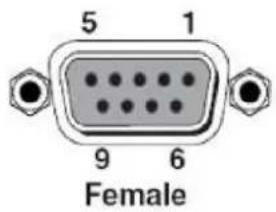
| Index | Pin |
| 1 | N/u |
| 2 | Tx(Matrix→PC) |
| 3 | Rx( Matrix ←PC) |
| 4 | N/u |
| 5 | Gnd |
| 6 | N/u |
| 7 | N/u |
| 8 | N/u |
| 9 | N/u |
Network control interface is also available, follow the TCP/IP protocol.
3.2.1. RS232 control and connection
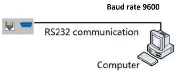
flowchart
graph LR
    A["Computer"] -->|RS232 communication| B["Baud rate 9600"]
3.2.2. Ethernet control and connection
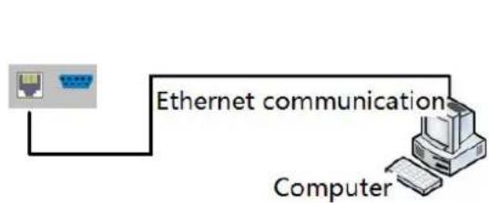
flowchart
graph LR
    A["Router Icon"] --> B["Ethernet communication"]
    B --> C["Computer"]
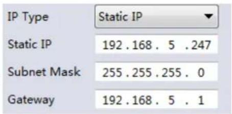
Note: Factory default network setting:
3.2.3. Front panel

- Mounting hole, for fixing.
- LCM display: display the output status of the matrix.
- LOCK button: When the button is activated, the button light is on, and the button OUTPUT1,2,... 8 buttons can be used to query the input and output corresponding state, the other buttons are locked. Press the button again, the light is off, unlock, can normally perform the button operation;
- TAKE button: Executive button, press this button to executive button function;
- Output buttons: Selecting output ports.
- Input button buttons: Selecting input ports.
Example:
Switch the input 6 to output 2:
(1) Check whether LOCK button LED is on or not, if on then press LOCK button to unlock the front panel;
(2) Press Output button 2, the LCM display as follows:
OU T:2
IN: 2
NOTE: Means the output 2 current input source is input 2
(3) Press input button 6, the LCM display as follows:
OUT:2
IN:<<6
(4) Press TAKE button, executive switching
(5) Finish switching process, the LCM display as follows:
OUT:2
IN:6
- ALL button: Press ALL + INPUT n +TAKE to switch input source n to all output ports
- SAVE button: Press SAVE + OUTPUT n + TAKE to save current routing scene to scene n
- Recall button: Press RECALL + OUTPUT n + TAKE to recall scene n as current display scene
4. Modular Matrix PC tool user guide (8x8 for example)
NOTE:
-
Default password: 111111
-
Press Ctrl+Shift+Fn+F2 can active the PC tool engineer mode, engineer mode support more functions, such as firmware version read and.
The PC tool needs no installation, support for serial control and network control. It is divided into six parts: Matrix Switch, Signal Setting, Fine tune: PQ &Position, OSD CTL, TV Wall, and Network Setting.
The UI as follows:

4.1. UART Control
Operation steps as follows:
- Connect PC and device with a straight serial port cable
- Run the PC control software (If already run, click to switch to the 'Matrix Switch' table)
- Click to switch 'Ctrl Mode' to 'UART'
- Click the combo box which is right to the 'Port', then select the correct COM port (There may be some COM ports connected to the PC)
- Click the 'Disconnected' button (which is right to 'Status') to connect to the device
- After connected successfully, the button right to 'Status' will be 'Connected' (If you click it now, it will disconnect from the device)

The UI after connected successfully will be as follows:
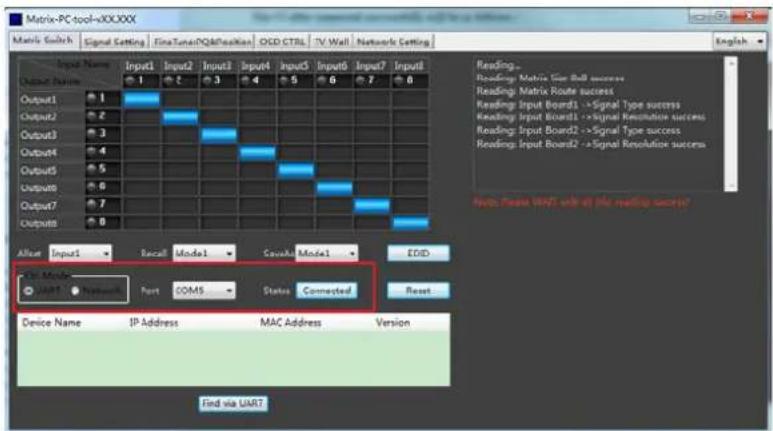
Note:
- The baud rate is 9600bps, and no manual configuration is required.
- Click the combo box of COM port after serial port cable connected to the PC, It will be updated automatically. If there's no COM port showing, Please make sure the driver is installed correctly and the reboot your PC and retry again.
- If the button which is right to the combo box shows 'Connected', and the software showing a message of 'device response timeout', please check the COM port whether is correct, the cable whether is connected good or the device whether is power on, and then re connect again.
4.2. Network Control:
4.2.1. Direct connection via Ethernet cable
Operation steps as follows:
- Connect the PC and device directly via an Ethernet cable
- Manually setting up the IP address of the PC, and the IP address of the PC and the device should be in a same network segment (The default IP address of the device is 192.168.0.247, and the default network mask of the device is 255.255.255.0). The screenshot of setting up the IP address are as follows:
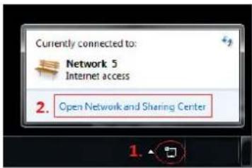
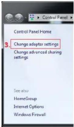
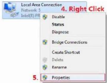
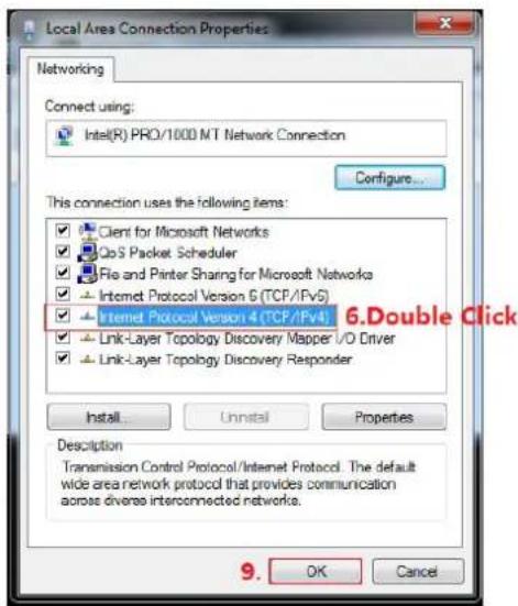
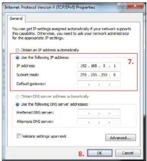
Manually setting up the IP address of the PC
- Run the PC control software (If the IP address of the PC changed after running the software, you should close it and run it again)
- Click to switch 'Ctrl Mode' to 'Network'
- Click the 'Search Device' button
- Click the device you want to control in the result list (When you click it, the software will read the network configuration such as network port and so on of the device automatically)
- Click the 'Disconnected' button (which is right to 'Status') to connect to the device
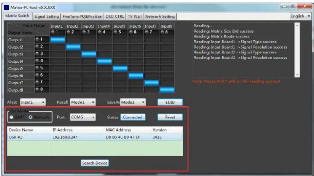
- After connected successfully, the button right to 'Status' will be 'Connected' (If you click it now, it will disconnect from the device)
The UI after connected successfully will be as follows:
4.2.2. Connection via LAN
Operation steps as follows:
- Connect the PC and the device to a same network router
- Setting up the IP address of the PC. Either manual(Static) mode or automatic (DHCP) mode is ok. Just make sure the IP address of the PC and the device are in a same network segment (When the IP type is obtain automatically, the network router that PC and device connected to should support HDCP function)
- Run the PC control software(If the IP address of the PC changed after running the software, you should close it and run it again)
- Click to switch 'Ctrl Mode' to 'Network'
- Click the 'Search Device' button
- Click the device you want to control in the result list (When you click it, the software will read the network configuration such as network port and so on of the device automatically)
- Click the 'Disconnected' button (which is right to 'Status') to connect to the device
- After connected successfully, the button right to 'Status' will be 'Connected' (If you click it now, it will disconnect from the device)
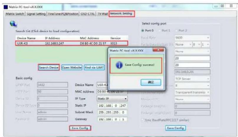
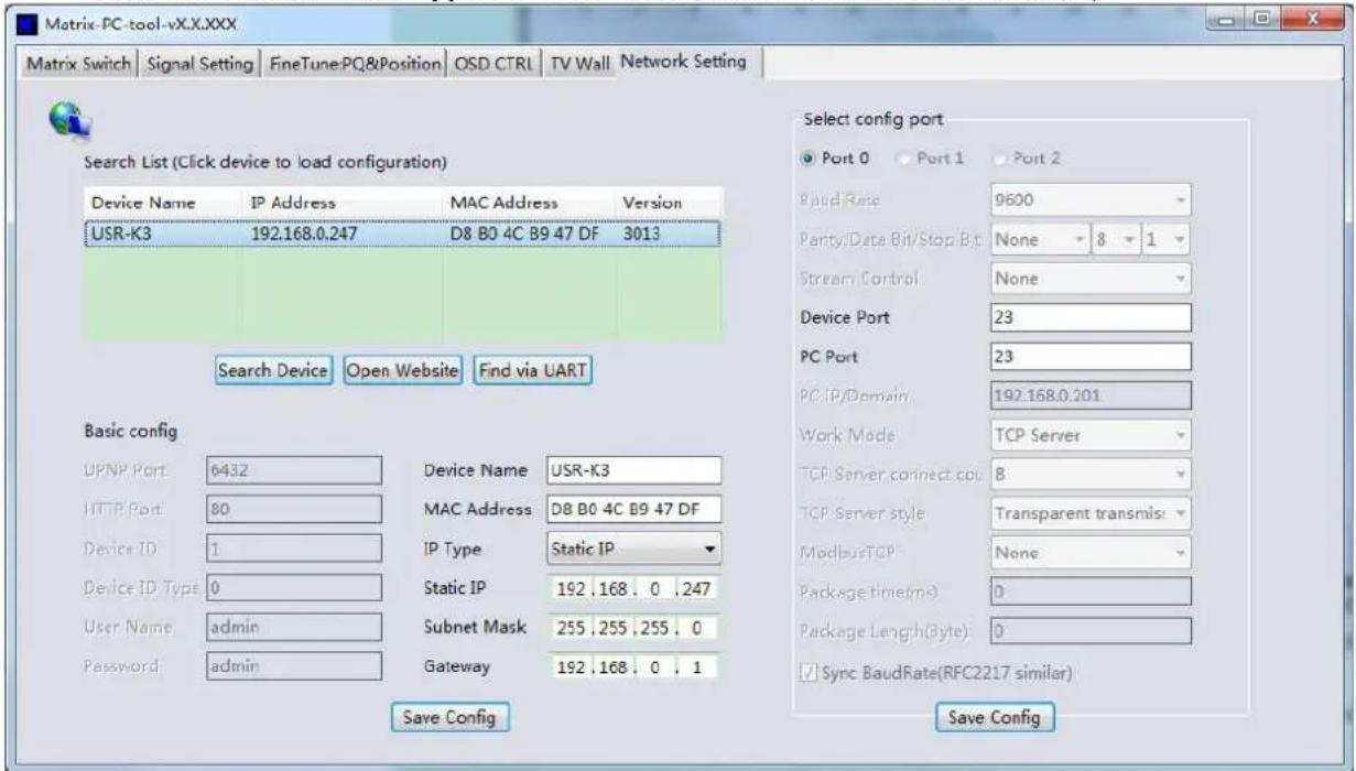
4.2.3. Configure the network module of the device
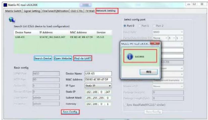
1. Configuration via UART
Step A: Connected to the device via serial port cable at 'Matrix Route' Table.

Setp B: Switch to 'Network Setting' Table
Setp C: Click the 'Find via UART' button to read the configuration of the device
Setp D: Modify the IP address or the IP address type
Step E: Click the 'Save Config' button to save data
Setp F: When the software shows a message of 'Success', Click the 'Find Via UART' to load configuration again to make sure your modification is saved successfully.
2. Configuration via Network
Setp A: Switch to 'Network Setting' Table
Setp B: Click the 'Search Device' button to search devices
Setp B: Click the device you want to configure in the result list (When you click it, the software will read the network configuration of the device automatically)
Setp C: Modify the IP address or the IP address type or other configuration.
Step D: Click the 'Save Config' button to save data
Setp E: When the software shows a message of 'Success', Click the 'Find Via UART' to load configuration again to make sure your modification is saved successfully.
NOTE:
-
Select the device, will display the matrix's network board information. User can edit the device's name, in order to better identify matrix. User can set dynamic IP/ static IP, subnet mask, gateway and other network information. At the same time, user can also set the device port. Serial port baud rate is 9600 (the user cannot change the baud rate, otherwise it will lead to the network control failed).
-
Configuration via UART only support modify IP address or IP address type. If you want to modify other configuration, please configure it via Network
4.2.4. Troubleshoot
1. Cannot search any devices
Cause A: The IP address type of the device is obtain automatically(DHCP), but currently connected direct via Ethernet cable or connected to a network device(router or switch and so on) which not support HDCP function.
Solution A: Setting up the IP address type of the device to static mode, or connecting the device to a network router which support HDCP function.
Cause B: The device is not power on.
Solution B: Please power on the device.
Cause C: The Ethernet cable is bad contact.
Solution C: Check the Ethernet cable's connection whether is ok.
Cause D: The IP address type of the PC is obtain automatically(DHCP), but currently connected direct via Ethernet cable or connected to a network device(router or switch and so on) which not support HDCP function.
Solution D: Setting up the IP address type of the PC to static mode, or connecting the device to a network router which support HDCP function.
Cause E: Unknown
Solution E: When using direct connection via Ethernet cable, please setting up the IP address type both of the PC and the device to static mode, and the IP address of the both should be in a same network segment. Or when using connection via LAN, connect the PC and the device to a same network router which support HDCP function.
2. The software show a message of 'device response timeout' after connected to the device.
Cause A: The IP address of the PC and the device are not in a same network segment.
Solution A: Setting up the IP address of the both, make sure the IP address are in a same network segment.
3. The software show a message of 'TCP connection failed' after connected to the device.
Cause: The IP address of the PC and the device are not in a same network segment.
Solution: Setting up the IP address of the both, make sure the IP address are in a same network segment.
Note: If the device's IP address type is Auto (DHCP), we can connect to the device via UART firstly, then click the 'Find Via UART' button to read the device's IP address. If the IP address of the device is 255.255.255.255 by this way, it means that the network device (the device connected to) does not support HDCP function.
4.3. Matrix Switch:
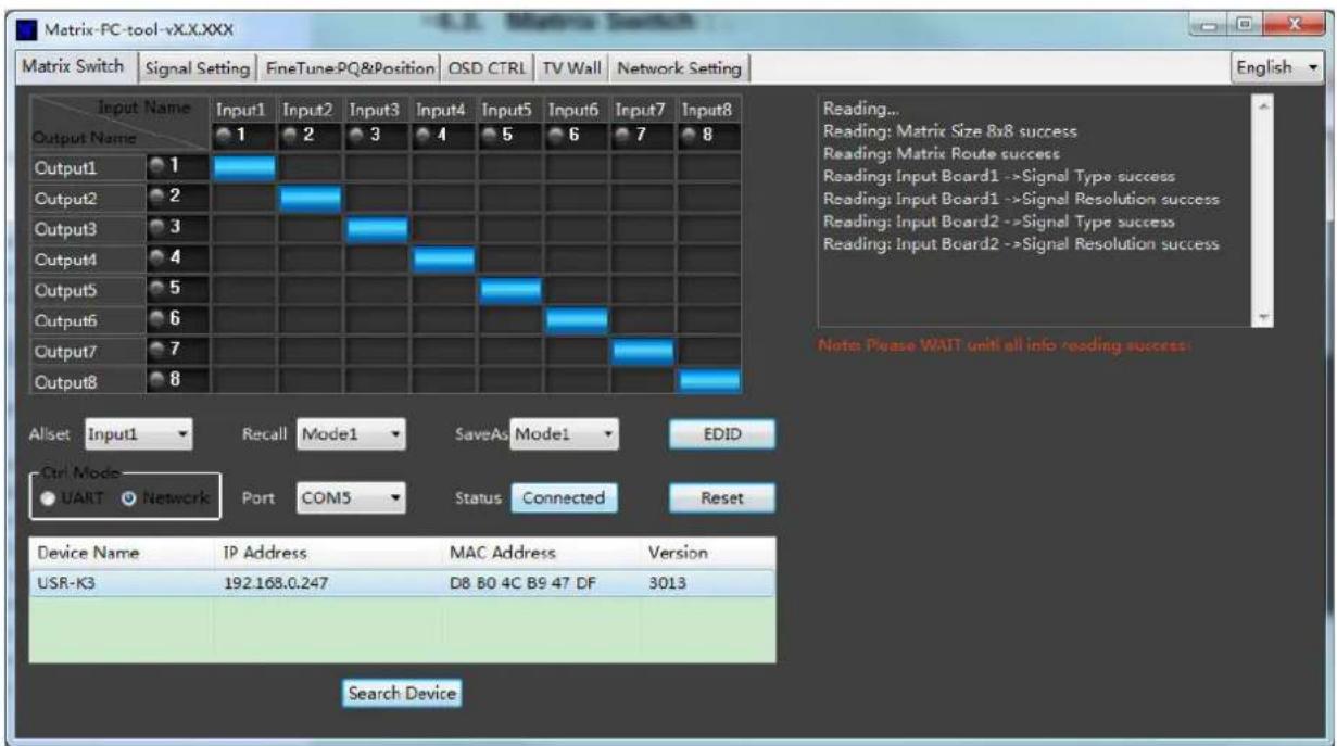
When the PC-tool connect to the matrix via UART or Network, the PC-tool will display the matrix's input and output information.
(1) User can click the mouse to switch the input; Can edit the input source name (for example, the user can edit the input 1 name to set-top box); Can also edit the output name to show which sink is connected (for example, the output 1 users can edit the name to TV).
(2) Support scene save (the user can pull down the corresponding drop-down menu, to save the current input and output relationship to mode X, support 8 different modes);
(3) Support scene recalls(the user can drop down the corresponding drop-down menu, to set the mode X input and output relationship to the matrix);
(4) Support one input output to all outputs (the user can drop down the "Allset" drop-down menu, to set the input X output to all the output ports).
(5) Support system reset: Click "Reset" button, after the user confirmed, then will reset the matrix to the factory default settings;
4.4. Signal Setting
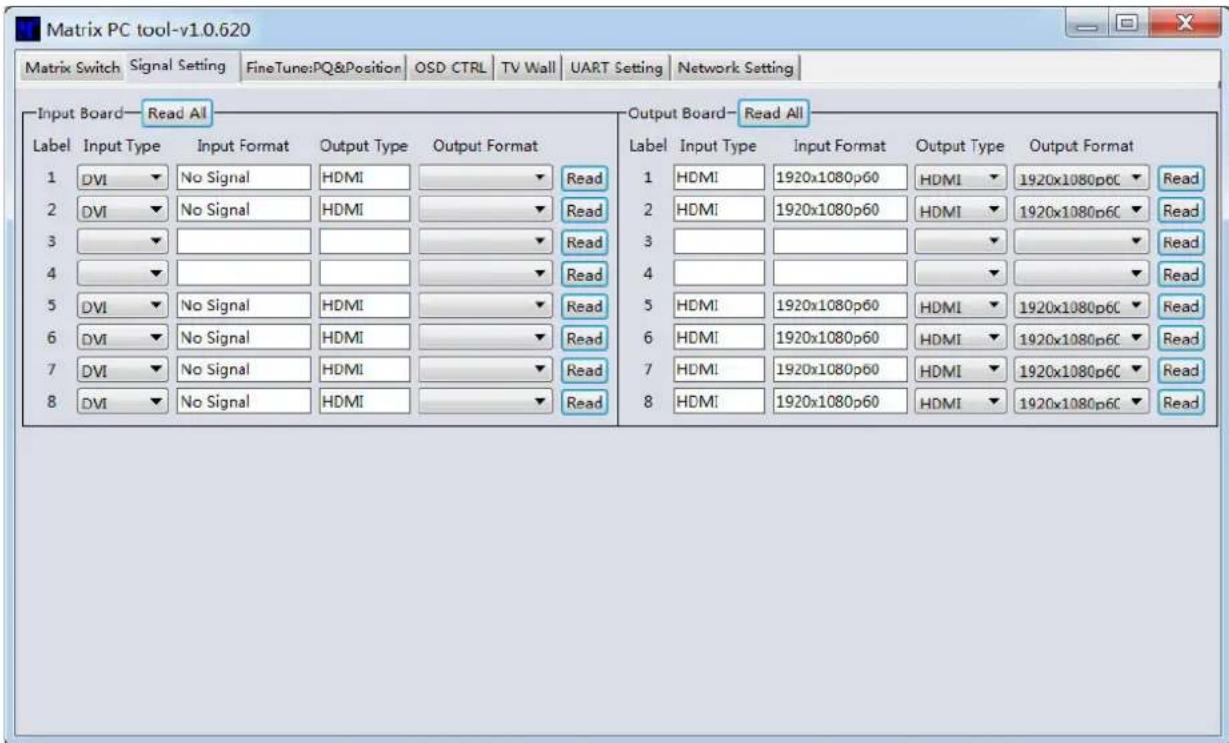
(1) Read and set the type of all input ports (DVI/VGA/YPbPr/CVBS), corresponding to the actual input terminal type: HDMI (DVI) /VGA/YPbPr/CVBS; Note: Only the DVI-U input board has this setting, SDI/HDBaseT/ fiber and other input boards, this setting is invalid.
(2) Read the input signal resolution of all the input ports;
(3) Read and set all the input boards' output resolution; The default output resolution is 108p 60HZ; Note: If no special need, please don't change the input board's output resolution, otherwise will affect the effect of seamless switching;
(4) Read the output board's input resolution;
(5) Read and set the output's output type; user must set the output terminal type according to the type of terminal that connected to the display device: HDMI/DVI/VGA/YPbPr/CVBS
Note: Only the DVI-U output board has this setting, SDI/HDBaseT/ fiber and other output boards, this setting is invalid.
(6) Read and set the output board's output resolution;
4.5. Fine Tune: PQ&Position
User can read and set the brightness/contrast/saturation/sharpness of the input board & output board, and also can read and set the video display position of the input board & output board;
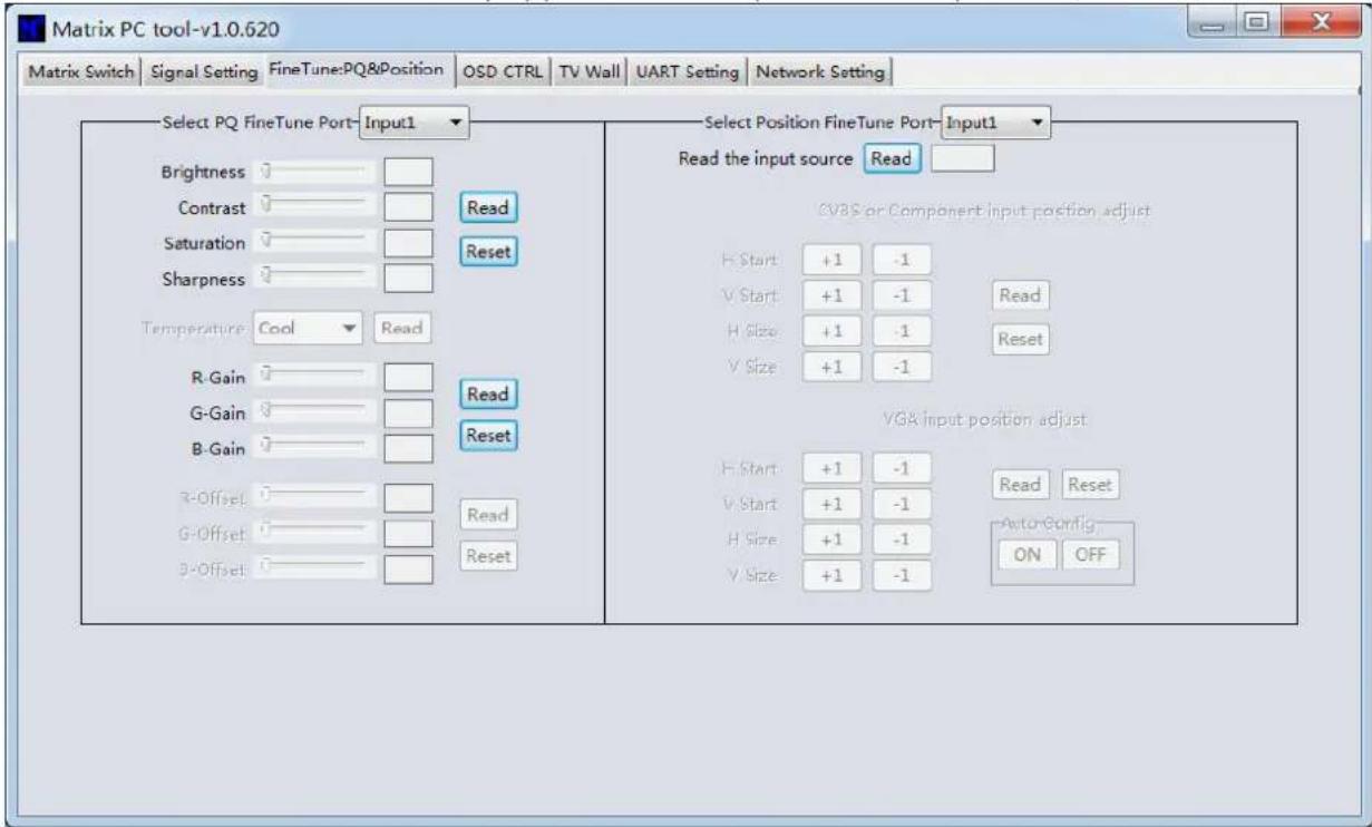
NOTE: Non special occasions, do not change the default settings; if there is a problem after the change, click Reset to return to the factory settings;
4.6. OSD CTRL:
This page is used to control the font overlay function. User can set the font overlay on/off, the background color, transparency, color, and other information;
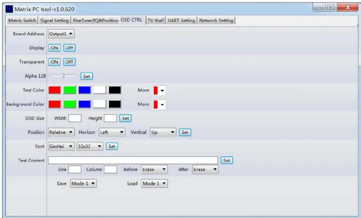
Guide:
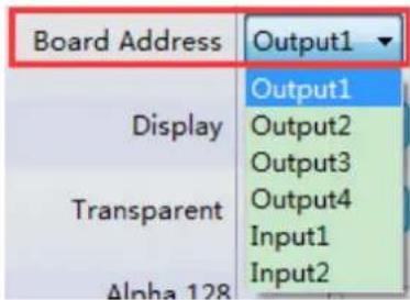
(1) Choose the output port which to display the character's by the drop down menu of the Board Address (currently only supports the font overlay on the output board);
(2) OSD Size: Set the area size for the character to display;
(3) Position: Set the font overlay position display on the screen;
(4) Font: Set the font type and the font size display on the screen;
(5) Text Content: Set the content that will display on the screen font overlay area;
(6) Line, Column: Set the line and column of the font display area that to display the font;
(7) Display: Font overlay on/off;
(8) Transparent: Background color of the font overlay on/off;
(9) Text color: font color;
(10) Background Color: Background color of the font;
Select the output port that you want to control
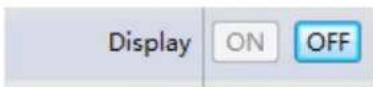
Turn ON/OFF the OSD
A. If the current state of the OSD is OFF, click the 'ON' button to turn it on. Then the OSD will come to show.

B. If the current state of the OSD is ON, click the 'OFF' button to turn it off. Then the OSD will disappear.
Set the background transparent or not

Set the alpha of the OSD
A. Drag to select the alpha value
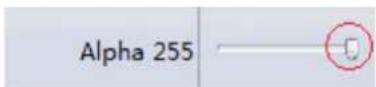
B. Click the 'Set' button

Set the text color or the background color
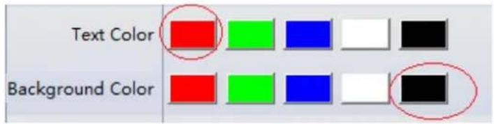
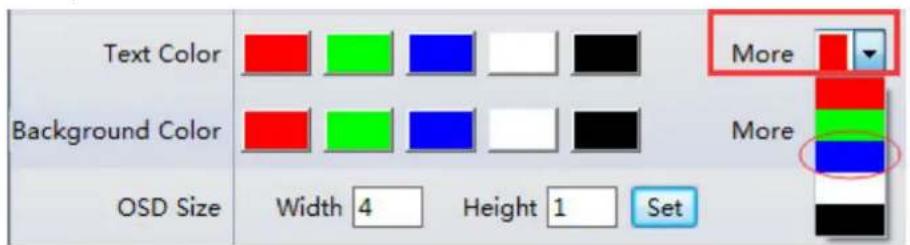
A. Click the color button to set. (Default 5 color: Red/Green/Blue/White/Black)
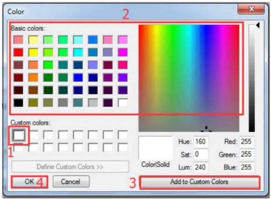
B. Use customer color: First Click the Combobox and select one default color to edit. Then choose the color you want in the Color window.

Set OSD Width and Height.
e.g. 4 characters and 1 line

Set the OSD position.
A. Set relative position

B. Set absolute position: Input coordinate value of the left-top of OSD and then click 'Set'. (e.g. (600,300))

Set the text font type and font size.

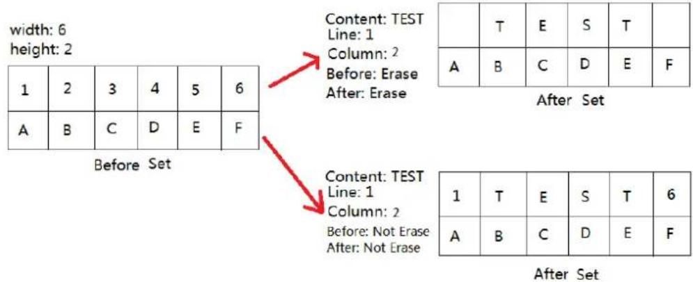
Set the OSD content:
A. Input the text. (e.g. "TEST")
B. Input the Line and Column value, which means where this text will be in the total OSD
C. Select the Erase choice before/after this text of the same line.

Example: OSD width is 6 and height is 2
4.7. TV Wall:
Set the TV wall display quantity: how many in one line (x), and how many in one column (y); The total display quantity is x^*y ;
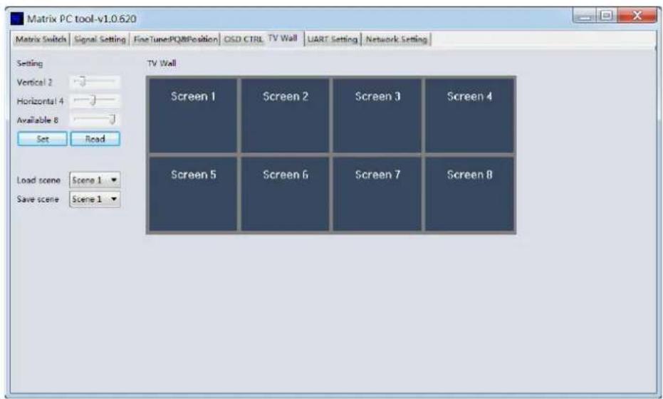
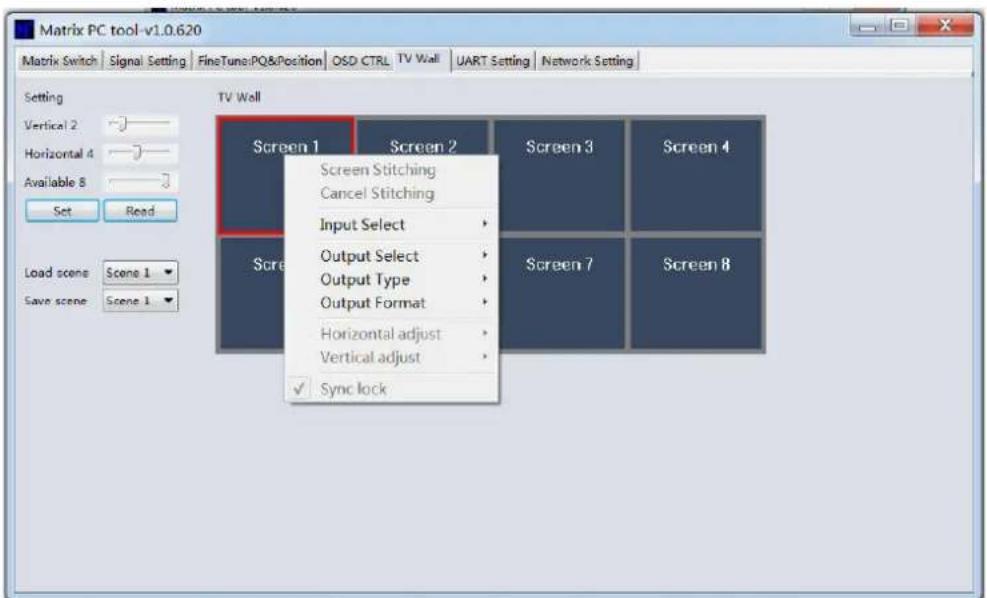
Select one display, right click, can see a menu as the following picture shows:
● Input Select: Select the input port, for the display to display (Input 1 \~ Input 8);
- Output Select: Set the output port that connect to the display, need according to the TV wall system setup status to set (Output 1 \~ Output 8); It means which output port connect to the display;
- Output Type: Set the terminal type of the output port, need to set according to the TV wall system setup status; (When in splicing mode, can only support HDMI)
- Output Format: Set the output port output resolution; (When in splicing mode, can only support 1080P 60HZ)
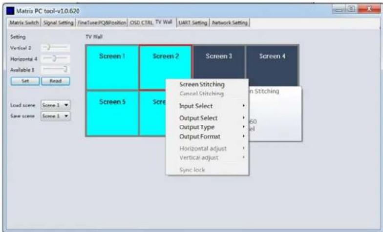
Click to select a screen, and then drag, select the screens to splice, right-click, and then click Screen Stitching to splicing;
Select the screen, which is splicing, right click, then will show menu as following picture shows:
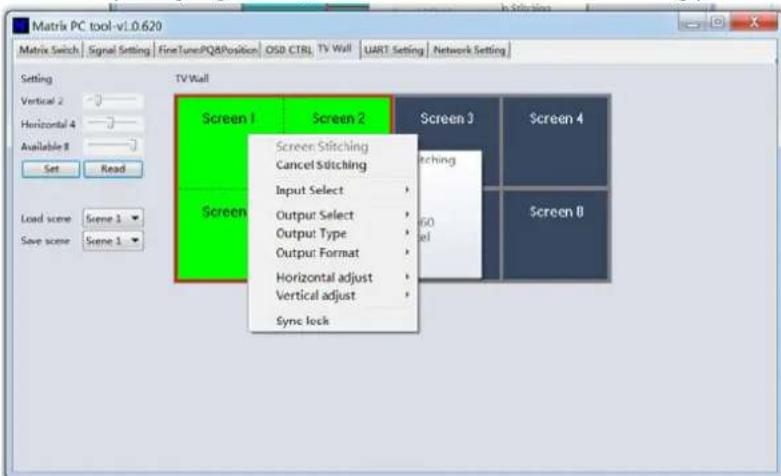
- Cancel Stitching: Cancel splicing;
● Input Select: Select the input port, for the display to display (Input 1 \~ Input 8); - Output Select: Set the output port that connect to the display, need according to the TV wall system setup status to set (Output 1 \~ Output 8); It means which output port connect to the display;
- Output Type: Set the terminal type of the output port, need to set according to the TV wall system setup status; (When in splicing mode, can only support HDMI)
- Output Format: Set the output port output resolution; (When in splicing mode, can only support 1080P 60HZ)
● Horizontal adjust: Set the TV wall screen horizontal frame width for each screen;
● Vertical adjust: Set the TV wall screen vertical frame width for each screen; - Sync lock: In order that all the screens that in splicing are sync lock all the time, must set the sync lock;
4.8. EDID control:
Click the 'EDID' button on Matrix Switch UI, then opens a EDID control Window
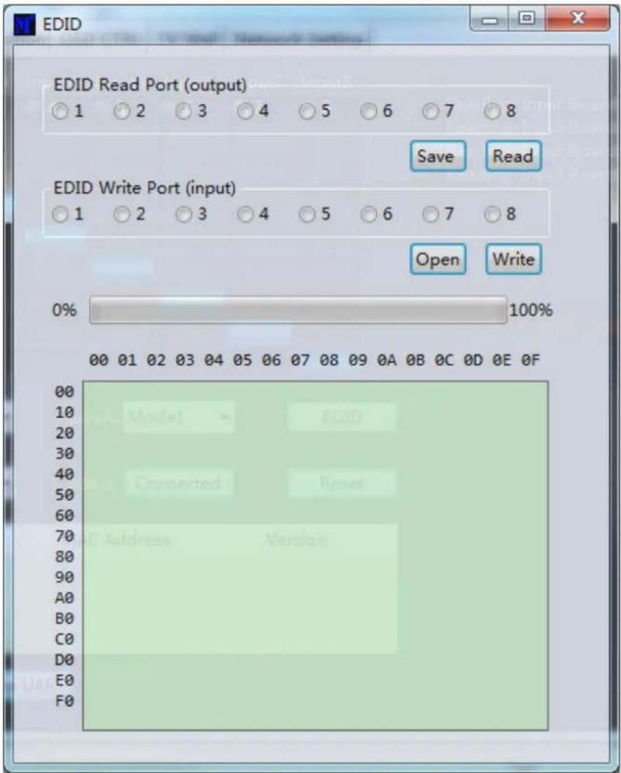
- Read EDID: Select the output port, then click the 'Read' button to read EDID
- Write EDID: First read a EDID from output port, or open a EDID file that saved before, then select the input port, then click the 'Write' button to write EDID
- Save EDID: After reading EDID successfully, Click 'Save' button, then choose the save path and file name for saving EDID.
5.Modular Matrix Control via Web:
(1) Do not know the matrix IP address: Click on the Network Settings page, and then click Search Device, and then select the device that found, click Open Website to open the web control web site, or can input the IP on the web browser, then enter the username: admin Password: admin, then can control the matrix switch function use the website;
NOTE: The computer IP and matrix IP must be in the same segment and the same local area network; For example, the matrix's IP is 192.168.1.xxx, then the computer IP must be 192.168.1.yyy; Otherwise need to change the matrix's IP or the computer's IP;
Note: the browser must support HTML5 feature, which must be IE10 and above;
(2) Know the matrix IP address: Input the IP on the web browser, then enter the username: admin Password: admin, then can control the matrix switch function use the website; Note: the browser must support HTML5 feature, which must be IE10 and above;
6. Modular Matrix Operating Cautions
(1) During installation, ensure the power supply ground is good, and ensure that the power supply for the device is 50/60Hz, AC110-240V;
(2) Do not place the matrix in the place where is too cold or overheated. In the wet environment or a long time not use, better to turn it off;
(3) Maintain a good ventilation of the working environment, to facilitate the timely discharge of heat;
(4) Make sure the signal cable, communication cable connect well to the matrix, then power on; AC power can't exceed 220V;
(5) Change the input source without turning off matrix may cause video not display correctly on the display. If this occur, please turn off the matrix, then power on, or re-plug the input board;
(6) HDMI/DVI cable should not exceed 10 meters, certified cable is recommended;
(7) If control via RS232 failed, please check whether the com port selected is right, and the RS232 cable is straight cable, not cross cable, the baud rate must set to 9600;
(8) If after switch, there is no video output, please check as follows:
- Check whether the switch command is executive or not, can use the PC-tool to see the input and out routing information;
- Check the source is work normal or not; Can direct connect the source's output to a display to see whether the source is ok or not;
- If the source is ok, then check the input board is ok or not, please refer to the PC-Tool's Signal Setting page to check whether the output port's input has signal or not, if there is no signal input, then the input board is broken, otherwise the input board is ok;
- If the input board is ok, check whether the output board is ok or not;
- If the above steps are still not sure why, please replace the input or output boards, Or refer to the professional maintenance person for help;
- Table of Contents
- Modular Seamless Matrix System .... 1
- Modular Matrix rear terminal view (8x8, DVI-U board for example) 4
- Modular Matrixperipheral device connection (8x8 for example) 5
- Input and output 5
- Modular Matrix PC tool user guide (8x8 for example) 7
- 5.Modular Matrix Control via Web: 23
- Modular Matrix Using Cautions....24
- Modular Seamless Matrix System
- Product profile
- Highlights 2: Gen-lock based Video Wall
- It's especially matched with LCD/LED Video Wall
- Highlights 3: Any kind of Font
- Product performance
- Specification & Parameters (Matrix, DVI-U as example)
- Specification & Parameters (2K seamless cards)
- Specification & Parameters (4K seamless cards)
- Modular Matrix rear terminal view (8x8, DVI-U board for example)
- Modular Matrix peripheral device connection (8x8 for example)
- Input and output
- Communication port and connection method
- RS232 control and connection
- Ethernet control and connection
- Front panel
- Modular Matrix PC tool user guide (8x8 for example)
- NOTE:
- The UI as follows:
- UART Control
- Network Control:
- Direct connection via Ethernet cable
- Operation steps as follows:
- Connection via LAN
- Configure the network module of the device
- Configuration via UART
- Configuration via Network
- Troubleshoot
- Cannot search any devices
- The software show a message of 'device response timeout' after connected to the device.
- The software show a message of 'TCP connection failed' after connected to the device.
- Matrix Switch:
- Signal Setting
- Fine Tune: PQ&Position
- OSD CTRL:
- Guide:
- Select the output port that you want to control
- Turn ON/OFF the OSD
- Set the background transparent or not
- Set the alpha of the OSD
- Set the text color or the background color
- Set OSD Width and Height.
- Set the OSD position.
- Set the text font type and font size.
- Set the OSD content:
- TV Wall:
- EDID control:
- 5.Modular Matrix Control via Web:
- Modular Matrix Operating Cautions
Brand : DVDO
Model : MATRIX-1616-C
Category : Router