SVC-300 - Audio OSD Audio - Free user manual and instructions
Find the device manual for free SVC-300 OSD Audio in PDF.


User questions about SVC-300 OSD Audio
0 question about this device. Answer the ones you know or ask your own.
Ask a new question about this device
Download the instructions for your Audio in PDF format for free! Find your manual SVC-300 - OSD Audio and take your electronic device back in hand. On this page are published all the documents necessary for the use of your device. SVC-300 by OSD Audio.
USER MANUAL SVC-300 OSD Audio
- Find out the minimum impedance of the amplifier. This information may be found in the manual or on the back of amplifier, near the speaker terminals. It is measured in ohms.
- Figure out the total number of speaker pairs to be used.
- Determine the correct switch setting using the chart below.
- Set the switch. Make sure that each volume control's switch setting is consistent throughout the whole system.
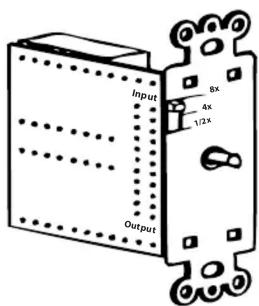
To prevent from overloading and damaging the amplifier, the switch must be set correctly to match the impedance of the speaker system to a level equal to or greater than the impedance of the amplifier.
| No. of 8 ohm pairs | 1 | 2 | 3 | 4 | 5 | 6 | 7 | 8 |
| Switch Settings | 1/2x | 1/2x | 4x | 4x | 8x | 8x | 8x | 8x |
Installation Instruction for the SVC-100
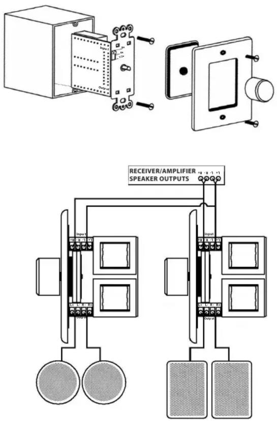
The SVC-100 is simple to install. Pay attention to the following steps:
- Route the cable into the volume control J-box in a way that allows for easy access to the connectors on the SVC-100.
- Make sure to use the integral strain reliefs where appropriate when routing the cable in the J-box.
- Mark the input and output cables accordingly for easy installation.
- Strip the insulation off the end of each of the eight individual wires (four from the amplifier and four to the speakers) at about 1/4". Twist exposed ends together.
- Connect the leads from amplifier to the volume control connector according to the labeled Input L [+, -] and R [+, -].
- Connect the speakers wires to the connector labeled Output L [ + , - ] and R [ + , - ]. Speaker wires typically use the following color configuration.
- Red/Black = right speaker Red = positive [ + ] Black = ground [- ]
- White/Green = left speaker White = positive [ + ] Green = ground [ - ]
- Insert the volume control into the J-box. Mount carefully, making sure that no wires are pinched or shorted.
OSD Audio Limited Warranty
OSD Audio will repair or replace any defect in material or workmanship which occurs during normal use of this product with new or rebuilt parts, free of charge in the USA, for five years from the date of original purchase. This warranty does not cover damages in shipment, failures caused by other products not supplied by OSD Audio or failures due to accident, misuse, or alteration of the equipment. This warranty is extended only to the original purchaser, and a purchase receipt, invoice, or other proof or original purchase date will be required before warranty repairs are provided.
Mail in service can be obtained during the warranty period by emailing RMA@osdaudio.com. A Return Authorization(RMA) number must be obtained in advance and be marked on the outside of the shipping carton.
This warranty gives you specific legal rights, and may have other rights (which vary from state to state). If a problem with this product develops during or after the warranty period please contact OSD Audio, your dealer, or any factory-authorized service center.
Brand : OSD Audio
Model : SVC-300
Category : Audio