
WISE-4610-NA - Industrial Automation Advantech - Free user manual and instructions
Find the device manual for free WISE-4610-NA Advantech in PDF.


| Product Type | Wireless IoT Gateway |
| Dimensions (W x H x D) | 130 x 94 x 30 mm |
| Weight | 250 g |
| Power Supply | 10–30 VDC, 2-pin terminal block |
| Power Consumption | Typ. 2.5 W |
| Wireless Interfaces | LoRa (868/915 MHz), Wi-Fi 802.11 b/g/n, Bluetooth 4.2 |
| Sensor Inputs | 4 x analog (0–10 V / 4–20 mA), 4 x digital (dry contact) |
| Data Logging | Internal memory up to 100,000 records |
| Cloud Connectivity | WISE-PaaS, MQTT, HTTP/HTTPS |
| Operating Temperature | -10 °C to 60 °C |
| Protection Rating | IP30 |
| Mounting | DIN rail or wall mount |
| Maintenance | Clean with dry cloth; avoid moisture and dust accumulation |
| Safety | Comply with local electrical codes; disconnect power before maintenance |
| Spare Parts | Power adapter (optional), mounting brackets |
| Certifications | CE, FCC, RoHS |
Frequently Asked Questions - WISE-4610-NA Advantech
User questions about WISE-4610-NA Advantech
0 question about this device. Answer the ones you know or ask your own.
Ask a new question about this device
Download the instructions for your Industrial Automation in PDF format for free! Find your manual WISE-4610-NA - Advantech and take your electronic device back in hand. On this page are published all the documents necessary for the use of your device. WISE-4610-NA by Advantech.
USER MANUAL WISE-4610-NA Advantech
The documentation and the software included with this product are copyrighted 2024 by Advantech Co., Ltd. All rights are reserved. Advantech Co., Ltd. also reserves the right to improve the products described in this manual at any time without notice. No part of this manual may be reproduced, copied, translated, or transmitted in any form or by any means without the prior written permission of Advantech Co., Ltd. The information provided in this manual is intended to be accurate and reliable. However, Advantech Co., Ltd. assumes no responsibility for its use, nor for any infringements of the rights of third parties that may result from its use.
Acknowledgments
Intel and Pentium are trademarks of Intel Corporation.
Microsoft Windows and MS-DOS are registered trademarks of Microsoft Corp.
All other product names or trademarks are properties of their respective owners.
Product Warranty (2 years)
Advantech warrants the original purchaser that each of its products will be free from defects in materials and workmanship for two years from the date of purchase.
This warranty does not apply to any products that have been repaired or altered by persons other than repair personnel authorized by Advantech, or products that have been subject to misuse, abuse, accident, or improper installation. Advantech assumes no liability under the terms of this warranty as a consequence of such events.
Because of Advantech's high quality-control standards and rigorous testing, most customers never need to use our repair service. If an Advantech product is defective, it will be repaired or replaced free of charge during the warranty period. For out-of-warranty repairs, customers are billed according to the cost of replacement materials, service time, and freight. Please consult your dealer for more details.
If you believe your product is defective, follow the steps outlined below:
-
Collect all the information about the problem encountered. (For example, CPU speed, Advantech products used, other hardware and software used, etc.) Note anything abnormal and list any onscreen messages displayed when the problem occurs.
-
Call your dealer and describe the problem. Please have your manual, product, and any helpful information readily available.
-
If your product is diagnosed as defective, obtain a return merchandise authorization (RMA) number from your dealer. This allows us to process your return more quickly.
-
Carefully pack the defective product, a completed Repair and Replacement Order Card, and proof of the purchase date (such as a photocopy of your sales receipt) into a shippable container. Products returned without a proof of purchase date are not eligible for warranty service.
-
Write the RMA number clearly on the outside of the package and ship the package prepaid to your dealer.
Part No. Edition 1
Printed in Taiwan September 2024
Declaration of Conformity
CE
This product has passed the CE test for environmental specifications when shielded cables are used for external wiring. We recommend the use of shielded cables. This type of cable is available from Advantech. Please contact your local supplier for ordering information.
Test conditions for passing also include the equipment being operated within an industrial enclosure. In order to protect the product from damage caused by electrostatic discharge (ESD) and EMI leakage, we strongly recommend the use of CE-compliant industrial enclosure products.
FCC Class A
This equipment has been tested and found to comply with the limits for a Class A digital device, pursuant to part 15 of the FCC Rules. These limits are designed to provide reasonable protection against harmful interference when the equipment is operated in a commercial environment. This equipment generates, uses, and can radiate radio frequency energy and, if not installed and used in accordance with the instruction manual, may cause harmful interference to radio communications. Operation of this equipment in a residential area is likely to cause harmful interference. In this event, users are required to correct the interference at their own expense.
Technical Support and Assistance
- Visit the Advantech website at www.advantech.com/support to obtain the latest product information.
- Contact your distributor, sales representative, or Advantech's customer service center for technical support if you need additional assistance. Please have the following information ready before calling:
– Product name and serial number
– Description of your peripheral attachments
– Description of your software (operating system, version, application software, etc.)
– A complete description of the problem
– The exact wording of any error messages
研華股份有限公司
Warnings, Cautions, and Notes
Warning! Warnings indicate conditions that if not observed may cause personal injury!

Caution! Cautions are included to help prevent hardware damage or data losses. For example, "Batteries are at risk of exploding if incorrectly installed. Do not attempt to recharge, force open, or heat the battery. Replace the battery only with the same or equivalent type as recommended by the manufacturer. Discard used batteries according to the manufacturer's instructions."
Note! Notes provide additional optional information.

Document Feedback
To assist us with improving this manual, we welcome all comments and constructive criticism. Please send all feedback in writing to support@advantech.com.
Packing List
Before system installation, check that the items listed below are included and in good condition. If any item is missing or damaged, contact your dealer immediately:
1 x WISE-4610 module
1 x Antenna
1 x Mount bracket
1 x WISE-4610 startup manual
Note! I/O boards for pairing with WISE-4610 are available for order:
WISE-S614 4AI/4DI with M12 Connectors
WISE-S614T 4AI/4DI with Terminal Block
WISE-S615T 4RTD with Terminal Block
WISE-S615 4RTD with M12 Connectors
WISE-S617 2AI/2DI/1DO/1RS-485 with M12 Connectors
WISE-S617T 2AI/2DI/1DO/1RS-485 with Terminal Block
WISE-S672 6DI/1RS-485/1RS-485 or RS-232 with M12 Connectors

Note! A micro-B USB cable for configuring WISE-4610 nodes is available for order:

1700023619-01 Micro USB type-B male to USB type-A male cable, 1 M
Note! An M12 connector and cable for I/O or power wiring is available for order:

1654011516-01 M12, A-code, 8 Pin, Male
1655005903-01 M12, A-code, 4 Pin, Female
1700028162-01 M12, A-code, 4 pin, Female with 1M cable
1700028163-01 M12, A-code, 8 Pin, Male with 1M cable
Safety Instructions
- Read these safety instructions carefully.
- Retain this user manual for future reference.
- Disconnect the equipment from all AC outlets before cleaning. Use only a damp cloth for cleaning. Do not use liquid or spray detergents.
- For pluggable equipment, the power outlet socket must be located near the equipment and easily accessible.
- Place the equipment on a reliable surface during installation. Dropping or letting the equipment fall may cause damage.
- The openings on the enclosure are for air convection. Protect the equipment from overheating. Do not cover the openings.
- Ensure that the voltage of the power source is correct before connecting the equipment to a power outlet.
- Position the power cord away from high-traffic areas. Do not place anything over the power cord.
- All cautions and warnings on the equipment should be noted.
- If the equipment is not used for a long time, disconnect it from the power source to avoid damage from transient overvoltage.
- Never pour liquid into an opening. This may cause fire or electrical shock.
- Never open the equipment. For safety reasons, the equipment should be opened only by qualified service personnel.
- If one of the following occurs, have the equipment checked by qualified service personnel:
■ The power cord or plug is damaged. - Liquid has penetrated the equipment.
■ The equipment has been exposed to moisture.
The equipment is malfunctioning, or does not operate according to the user manual.
■ The equipment has been dropped and damaged.
■ The equipment shows obvious signs of breakage. - Do not leave the equipment in an environment with a storage temperature of below -20 °C (-4 °F) or above 60 °C (140 °F) as this may cause damage. The equipment should be kept in a controlled environment.
- CAUTION: Batteries are at risk of exploding if incorrectly replaced. Replace only with the same or equivalent type as recommended by the manufacturer. Discard used batteries according to the manufacturer's instructions.
- According to IEC 704-1:1982 standards, the sound pressure level at the operator's position does not exceed 70 dB (A).
DISCLAIMER: These instructions are provided in accordance with IEC 704-1. Advantech disclaims all responsibility for the accuracy of any statements contained herein.
Safety Precautions - Static Electricity
Follow these simple precautions to protect yourself from harm and the products from damage:
- Disconnect the power supply before making any configuration changes. The sudden rush of power after connecting a jumper or installing a card may damage sensitive electronic components.
NCC 警语
根據低功率電波輻射性電機管理辦法
Federal Communication Commission Interference Statement
This device complies with Part 15 of the FCC Rules. Operation is subject to the following two conditions: (1) the device may not cause harmful interference, and (2) the device must accept any interference received, including interference that may cause undesired operation.
COUNTRY CODE SELECTION (WLAN DEVICES)
The country code selection option is available for the non-U.S. model only, and is not available for any U.S. models. According to the FCC regulations, all Wi-Fi products marketed in the U.S. must be fixed to U.S. operation channels only.
Industry Canada statement:
This device complies with ISED's licence-exempt RSSs. Operation is subject to the following two conditions: (1) the device may not cause harmful interference, and (2) the device must accept any interference received, including interference that may cause undesired operation.
1.1 LoRa and LoRaWAN.... 2
1.2 WISE-4610 Feature Highlights.... 2
1.3 WISE Series Family 2
Table 1.1: WISE Series Family....2
1.4 System Diagram....3
Figure 1.1 WISE-4610 System Diagram.... 3
1.5 Battery Switch 3
Figure 1.2 WISE-4610 Battery Switch 3
1.6 LED Indicators....4
Figure 1.3 WISE-4610 LED Indicators.... 4
Table 1.2: LED Indicators 4
Table 1.3: 5
1.7 Membrane Button....5
Figure 1.4 WISE-4610 Membrane Button....5
1.8 Packing List....6
Chapter 2 Hardware Installation ....7
2.1 Modular Design 8
Figure 2.1 I/O Module Installation....8
2.2 System Dimensions 9
Figure 2.2 WISE-4610 Dimensions 9
Figure 2.3 WISE-S600 Series I/O Module Dimensions ..... 10
2.3 DIN-Rail Mounting.... 10
Figure 2.4 WISE-4000 Series Mount Kit Dimensions 10
Figure 2.5 DIN-Rail Mounting Adapter Installation ..... 11
Figure 2.6 DIN-Rail Mounting (Front View).... 11
Figure 2.7 DIN-Rail Mounting (Rear View) 12
2.4 Wall Mounting 12
Figure 2.8 Wall Mount Bracket Installation 12
2.5 Pole Mounting 13
Figure 2.9 Pole Mount Bracket Installation (Front View) ..... 13
Figure 2.10 Pole Mount Bracket Installation (Rear View) ..... 13
Chapter 3 Hardware Specifications....15
3.1 LoRa (Model: WISE-4610P).... 16
3.2 GPS....16
3.3 General 16
3.4 Power 17
3.5 I/O Specifications 17
3.5.1 WISE-S614/WISE-S614T I/O Module.... 17
3.5.2 WISE-S615/WISE-S615T RTD I/O Module 18
3.5.3 WISE-S617/WISE-S617T I/O Module.... 18
3.5.4 WISE-S672 I/O Module.... 19
3.6 I/O Pin Assignment 21
Figure 3.1 WISE-S600 Pin Out....21
Table 3.1: I/O Pin Assignment....21
3.7 Pin Assignment of WISE-S600T I/O Module with Terminal Block Connectors....22
3.8 Application Wiring of WISE-S600 I/O Module with M12 Connectors ..... 23
3.8.1 WISE-S614 I/O Application Wiring.... 23
Figure 3.2 WISE-S614 I/O Application Wiring 23
3.8.2 WISE-S615 I/O Application Wiring 23
Figure 3.3 WISE-S615 I/O Application Wiring 23
3.8.3 WISE-S617 I/O Application Wiring 24
Figure 3.4 WISE-S617 I/O Application Wiring Diagram ..... 24
3.8.4 WISE-S672 Application Wiring 24
Figure 3.5 WISE-S672 Application Wiring Diagram ...... 24
3.9 Application Wiring of WISE-S600T I/O Module with Terminal Block ..... 25
3.9.1 WISE-S614T I/O Application Wiring 25
Figure 3.6 WISE-S614T I/O Application Wiring Diagram ..... 25
3.9.2 WISE-S617T I/O Application Wiring 25
Figure 3.7 WISE-S617T I/O Application Wiring Diagram ..... 25
3.10 Power Supply Wiring.... 26
3.11 Block Diagram.... 26
Figure 3.8 WISE-4610 Block Diagram....26
3.12 Configuration Interface.... 26
Chapter 4 Software Functions....27
4.1 System Structure 28
4.2 Interface Design.... 30
4.2.1 LoRaWAN Functions 30
Table 4.1: LoRaWAN Functions.... 30
Table 4.2: Configuration Parameters for LoRaWAN .... 30
4.2.2 Positioning 31
Table 4.3: Features ...... 31
Table 4.4: Measurement Data.... 31
Table 4.5: Configurations ...... 32
4.2.3 LED Indicator Behaviors 32
Table 4.6: LED Indicator Behaviors.... 32
Table 4.7: 33
4.2.4 Battery Charging.... 33
Table 4.8: 33
Table 4.9: 34
Table 4.10: Battery Events ...... 34
Table 4.11: Battery Temperature and Charging.... 35
4.2.5 Membrane Button 35
4.2.6 Multiple Power Sources 36
Table 4.12: 36
Table 4.13: 36
4.3 Connection Setting on WISE-4610 37
4.3.1 Configure WISE-4610 by Using WISE-Studio 37
Appendix A Modbus Table with WISE-4610 ..... 47
Table A.1: WISE-4610-S617 (for WISE-6610 LoRaWAN GW). 48
Table A.2: *AI Status: (1st Register at Low Address) 50
Table A.3: *4 Power source 50
Table A.4: Modbus Type Code 50
Table A.5: WISE-4610-S615 (for WISE-6610 LoRaWAN GW) . 51
Table A.6: *AI Status: (1st Register at Low Address) 52
Table A.7: *4 Power source 53
Table A.8: Modbus Type Code 53
Chapter 1
Product Introduction
1.1 LoRa and LoRaWAN
A low-power, wide-area network (LPWAN) is a type of wireless telecommunication wide-area network designed to allow long-range communications at a low bit rate between IoT devices, such as battery-operated sensors.
LPWAN offers multi-year battery lifetime and is designed for sensors and applications that need to send small amounts of data over long distances a few times per hour from varying environments.
LoRa and LoRaWAN belong to the category of non-cellular LPWAN wireless communication network protocols that enable long-range data transmissions with low power consumption, and operate in the license-free spectrum.
LoRa is a patented digital wireless data communication IoT technology. The technology is presented in two parts — LoRa, the physical layer (PHY), and the communication protocol built upon the underlying LoRa physical layer. The communication layer may be LoRaWAN, an open-source communication protocol defined by the LoRa Alliance consortium.
The difference between LoRa and LoRaWAN is that LoRaWAN defines the communication protocol and system architecture for the network, while the LoRa physical layer enables the long-range communication link.
1.2 WISE-4610 Feature Highlights
Advantech's WISE-4610 LoRa wireless I/O module can be configured to support either a public or private LoRa using the WISE Studio utility via a USB port.
For outdoor applications, WISE-4610 can be equipped with optional GPS, a solar rechargeable battery, and an IP65-rated enclosure to protect from water and dust ingress.
The WISE-4610 wireless I/O module features an intelligent modular design that supports various I/O configurations according to usage requirements. This allows users to easily integrate their desired I/O module (WISE-S614/S615/S617/S672) with the WISE-4610 module.
1.3 WISE Series Family
Table 1.1: WISE Series Family
Function Model Description
| LoRa Wireless I/O Module WISE-4610 Outdoor LoRa wireless I/O module | ||
| I/O Module | WISE-S672 | I/O module with 6 x digital inputs, 1 x RS-485 port, and 1 x RS-232/485 port |
| WISE-S617 | I/O module with 2 x analog input, 2 x digital input, 1 x digital output, 1 x RS-485 port | |
| WISE-S615 | I/O module with 4 x RTD channels | |
| WISE-S614 | I/O module with 4 x digital inputs and 4 x analog inputs | |
| LoRa Gateway | WISE-6610 LoRaWAN Gateway | |
1.4 System Diagram
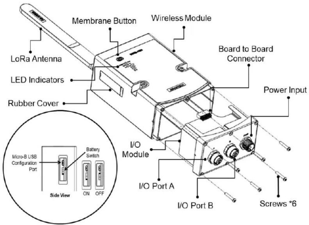
Figure 1.1 WISE-4610 System Diagram
1.5 Battery Switch
The WISE-4610 module is equipped with a switch to turn the battery ON/OFF. This switch is located at the side of the WISE-4610 module. Simply open the rubber cover and flick the switch to turn ON/OFF the battery power.
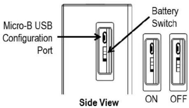
Figure 1.2 WISE-4610 Battery Switch
1.6 LED Indicators
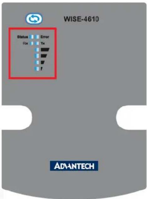
Figure 1.3 WISE-4610 LED Indicators
Table 1.2: LED Indicators
| LED Color State Description | |||
| Status Green | Fast blink(0.2 sec ON, 0.3 sec OFF) | Waiting for connection or connecting | |
| Slow blink(0.2 sec ON, 1.8 sec OFF) | Connecting and operating normally | ||
| Error Red | Fast blink(0.2 sec ON, 0.8 sec OFF) | Application errors. (*Note 1)■ Network registration timeout■ I/O Error■ FW error | |
| Slow blink(0.2 sec ON, 2.8 sec OFF) | ■ Low battery voltage (v <= 20%)■ Low RTC battery voltage■ Battery internal short is detected | ||
| Off No error | |||
| RF RX Green | On (0.2 sec ON) Received data from Gateway | ||
| Off Idle | |||
| RF TX Yellow | On Sending data to gateway | ||
| Off Idle | |||
| Signal Strength | 4 Green | On(if pressing the membrane button) | Main battery capacity■ All OFF - V <= 20%■ 1 ON - 20% < V < 40%■ 2 ON - 40% <= V < 60%■ 3 ON - 60% <= V < 80%■ 4 ON - V >= 80% |
*Note 1
| Table 1.3: | ||||||
| Error LED | Signal LEDs | Description | ||||
| 1st (poor) | 2nd (Okay) | 3rd (Good) | 4th (Full) | |||
| Error | Fast Blink | OFF OFF | OFF Fast Blink RF related Error | |||
| OFF OFF | Fast Blink OFF I/O Error | |||||
| OFF OFF | OFF OFF FW error | |||||
| Slow Blink | OFF OFF | OFF OFF Battery related Error | ||||
| OFF OFF | OFF OFF | OFF No error | ||||
Note! If WISE-4610 is powered by the battery, the LED indicators will turn off after 15 seconds to save power.

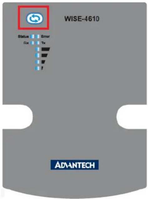
1.7 Membrane Button
Located at the front of the WISE-4610 module is a membrane button that can be used to switch between operating modes and to light up the LED indicators (refer to Section 4.2.9 "LoRaWAN Functions" for more information about the membrane button functions).
WISE-4610 LoRa Wireless I/O Module
1 x WISE-4610 module
1 x Antenna
1 x Mount bracket
■ 1 x WISE-4610 startup manual
WISE-S614/WISE-S614T 4AI/4DI I/O Module
■ 1 x WISE-S614 module
■ 1 x I/O information label
WISE-S615/WISE-S615T 4RTD I/O Module
■ 1 x WISE-S615 or WISE-S615T I/O Module
■ 1 x I/O Information Label
WISE-S617/WISE-S617T 2AI, 2DI, 1DO & 1RS-485 I/O Module
■ 1 x WISE-S617 or WISE-S617T I/O Module
■ 1 x I/O Information Label
WISE-S672 6DI/1RS-485/1RS-485 or RS-232 Module
■ 1 x WISE-S672 module
■ 1 x I/O information label
Note! Refer to the WISE-6610 user manual for information on how to configure a LoRaWAN gateway.

Note! A micro-B USB cable for configuring WISE-4610 is available for order:

■ 1700023619-01 Micro USB type-B male to USB type-A male cable, 1 M
Note! An M12 connector and cable for I/O or power wiring is available for order:

1654011516-01 M12 connector, 8 pin, male
1655005903-01 M12 connector, 4 pin, male
1700028162-01 M12 code-A, 4 pin, female cable for power wiring, 2 M
1700028163-01 M12 code-D, 8 pin, male cable for I/O wiring, 2 M
Chapter 2
Hardware Installation
The wireless sensor nodes for WISE-4610, like those for all WISE-4000 series modules, are designed as separate units. The procedure for installing these nodes in the module is explained in the following sections.
2.1 Modular Design
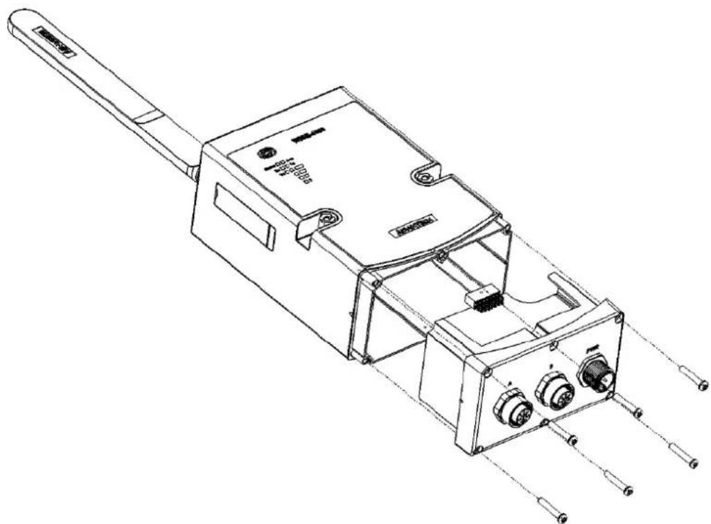
WISE-4610 features a modular design that supports various I/O configurations. The benefit of a modular design is that the same wireless board can be leveraged by different I/O modules via a board-to-board connector. This allows users to install two I/O modules according to their specific usage requirements. Moreover, the modules can be affixed to WISE-4610 using the six screws provided (as shown in Figure 2.1).
natural_image
Technical line drawing of a mechanical device with multiple ports and a handle (no text or symbols)Figure 2.1 I/O Module Installation
Note! The recommended screw torque is 2.5 \~ 3.0 kgf/cm².

2.2 System Dimensions
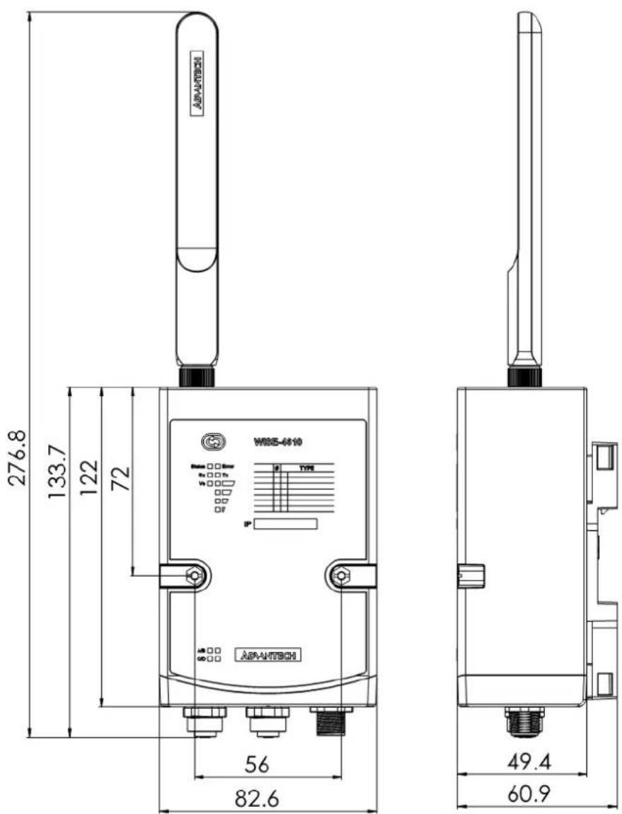
Figure 2.2 WISE-4610 Dimensions
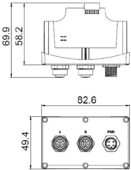
Figure 2.3 WISE-S600 Series I/O Module Dimensions
2.3 DIN-Rail Mounting
WISE-4610 modules can be fixed to a cabinet with mount rails. Use a flathead screw-driver to affix the DIN rail mounting adapter to the module. Then attach the end brackets provided with the product to prevent sliding.
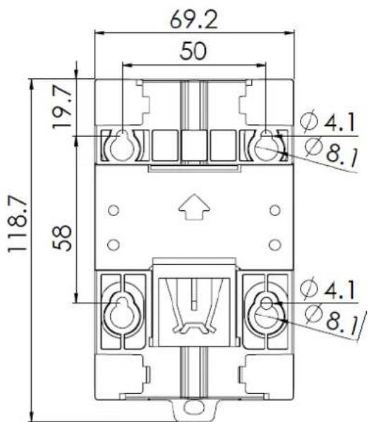
Figure 2.4 WISE-4000 Series Mount Kit Dimensions
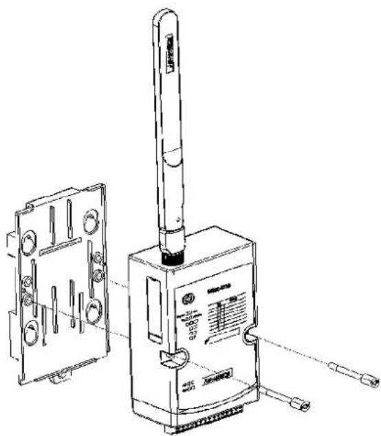
natural_image
Technical line drawing of a device with attached components and wiring (no text or symbols)Figure 2.5 DIN-Rail Mounting Adapter Installation
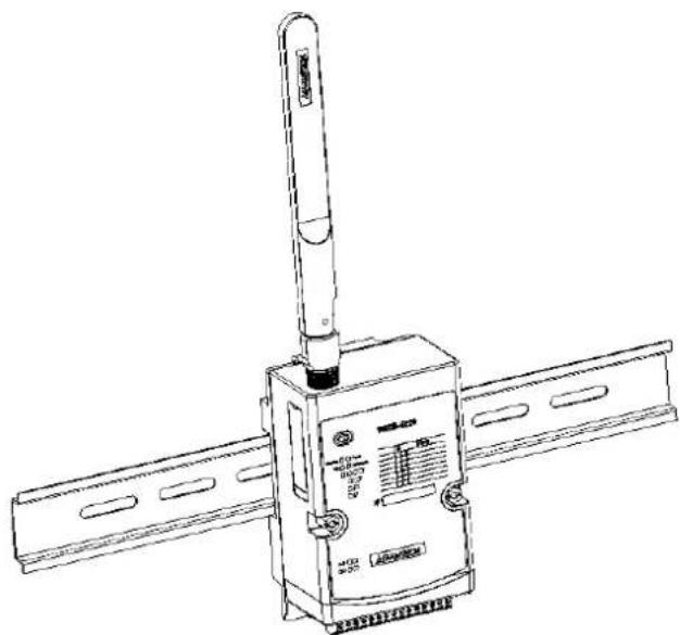
natural_image
Technical line drawing of a satellite communication module with antenna and control panel (no text or symbols)Figure 2.6 DIN-Rail Mounting (Front View)
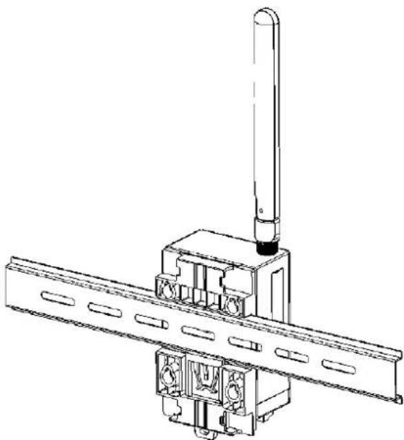
natural_image
Technical line drawing of a mechanical assembly with a vertical rod and mounting bracket (no text or symbols)Figure 2.7 DIN-Rail Mounting (Rear View)
2.4 Wall Mounting
The plastic wall-mount bracket provided with the product, can be used to mount WISE-4610 on a wall, panel, or cabinet.
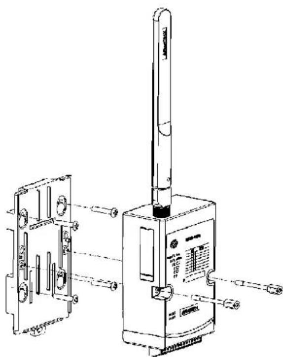
natural_image
Technical line drawing of a handheld device with internal components and mounting brackets (no text or symbols)Figure 2.8 Wall Mount Bracket Installation
2.5 Pole Mounting
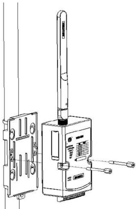
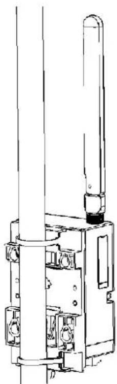
For pole mounting, feed the pole-mounting ring through the hole in the middle of the module. The pole-mounting ring must be unlocked with a screwdriver before inserting it into the module. To mount the module on the pole, tightly lock the pole-mounting ring.
natural_image
Technical line drawing of a handheld electronic device with ports and a vertical sensor (no text or symbols)Figure 2.9 Pole Mount Bracket Installation (Front View)
natural_image
Technical line drawing of a mechanical device with cylindrical components and mounting features (no text or symbols)Figure 2.10 Pole Mount Bracket Installation (Rear View)
Chapter 3
Hardware
Specifications
3.1 LoRa (Model: WISE-4610P)
Frequency Band: EU 863-870 (MHz)/US 902-928 (MHz)/AU 915-928 (MHz)/AS 919-924 (MHz)/JP 920-928 (MHz)
■ Spreading Factor: 7\~12
■ Transmit Power: Up to +18 dBm
■ Receiver Sensitivity: Up to -136 dBm at SF = 12/125 KHz
Data Rate:
- 50 kbps at FSK mode EU868
- 21.9 kbps at SF7 mode US915
- 5.47 kbps at SF7 mode JP923/AS923
Topology: Star
3.2 GPS
■ GNSS Systems: GPS, GLONASS, Galileo, BeiDou, QZSS, and SBAS signals
■ Maximum Update Rate:
– Single GNSS: Up to 18 Hz
– Concurrent GNSS: Up to 10 Hz
■ Positioning Accuracy:
- 2.5 m CEP (50% confidence)
– With SBAS: 2.0 m CEP (50% confidence)
Acquisition:
– Cold Starts: 57 s
- Aided Starts: 7 s
3.3 General
■ RTC Accuracy: ±2 s/day
■ Enclosure: PC + PBT
■ Mount Options: DIN rail, wall, and pole
■ Dimensions (W x H x D): 82 x 122 x 49 mm/3.22 x 4.8 x 1.92 in (without antenna)
- Operating Temperature:
- With rechargeable battery: 0 60^ C (32 \~ 140 °F)
- Without battery: -25 \~ 70 °C (-13 \~ 158 °F)
■ Storage Temperature:
- With rechargeable battery: -20 \~ 60 °C (-4 \~ 140 °F)
- Without battery: -40 \~ 85 °C (-40 \~ 185 °F)
■ Operating Humidity: 25 \~ 95% RH (non-condensing)
■ Storage Humidity: 0 \~ 95% RH (non-condensing)
Note! The storage and operation of WISE-4610 modules MUST be in environments that meet the temperature specifications.

Note! WISE-4610 modules can withstand operation in environments with less than 30% humidity. However, environments with low relative humidity are prone to causing electrostatic discharge issues. Therefore, users should take adequate precautions and use grounding straps, anti-static floor coverings, or similar equipment when manually handling the modules, especially in low-humidity environments.
Note! Batteries are at risk of exploding if it is incorrectly installed. Do not attempt to replace the battery yourself. Batteries should only be replaced by qualified service personnel.
3.4 Power
■ Power Input Voltage: 10 \~ 50 V DC
Power Consumption:
- WISE-4610: 11 W @ 24 V, when the battery is charging
■ Solar Panel Input Voltage: 17 \~ 50 V _DC
Battery Capacity: 4000 mAh
Battery Life: 6 months (with hourly data updates and daily GPS updates)
Note! The battery life is estimated for temperatures of 25 °C. Operation in low-temperature environments will reduce the battery life.

3.5 I/O Specifications
Power Connector: 1 x M12 4-pin code-A male connector with male pins
I/O Connector: 2 x M12 8-pin code-D female connector with female pins
3.5.1 WISE-S614/WISE-S614T I/O Module
3.5.1.1 Digital Inputs
Channels: 4
■ Logic Level (Dry Contact):
- 0: Open
- 1: Close DI COM
Non-isolation
■ Supports 200 Hz counter input (32-bit + 1-bit overflow)
- Keep/discard counter value when power OFF
■ Supports 200 Hz Frequency Input
■ Supports inverted DI status
3.5.1.2 Analog Inputs
Channels: 4
■ Resolution: 16 bit
■ Sampling Rate: 1 Hz per channel
Accuracy:
■ Input Range: ±150 mV, ±500 mV, ±1 V, ±5 V, ±10 V, 0 \~ 150 mV, 0 \~ 500 mV, 0 \~ 1 V, 0 \~ 5 V, 0 \~ 10 V, 0 \~ 20 mA, 4 \~ 20 mA, ±20 mA
■ Input Impedance:
Isolation Voltage: 3000 Vdc
■ Common Mode Voltage: 350 V DC
■ Burn-Out Detection: Yes (4 \~ 20 mA only)
■ Supports data scaling and averaging
- ±0.1% of FSR (voltage)
- ±0.2% of FSR (current)
- > 2 MΩ (Voltage)
- 240 Ω (external resistor for current)
3.5.2 WISE-S615/WISE-S615T RTD I/O Module
3.5.2.1 Analog Input
■ Channels: 4 differential
■ Input Connections: 2, 3-wire
■ Input Impedance: 10 MΩ
■ Resolution: 15 bits
■ Sampling Rate: 1 Sample/s (MAX)
■ RTD Types and Temperature Ranges:
- Pt 100 RTD:
RTD 100 (a = 0.00385) -200 °C to 600 °C
RTD 100 (a = 0.00392) -200 °C to 600 °C
- Pt 1000 RTD:
Pt -40 °C to 160 °C
Accuracy: ±0.1% of FSR
CMR @ 50/60 Hz: 90 dB
■ NMR @ 50/60 Hz: 60 dB
■ Span Drift: ± 100 ppm/°C
3.5.3 WISE-S617/WISE-S617T I/O Module
3.5.3.1 Digital Input
Channel: 2
■ Logic Level (Dry Contact):
Non-isolation
■ Supports 32-bit counter input function (maximum signal frequency: 200 Hz)
■ Supports keep/discard counter value when power OFF
■ Supports frequency input function (maximum signal frequency: 200 Hz)
■ Supports inverted digital input status
- 0: Open
- 1: Close to DI COM
3.5.3.2 Analog Input
Channels: 2
■ Resolution: 16 bit
■ Sampling Rate: 1 Hz per channel
Accuracy:
■ Input Range: ±1 V, ±5 V, ±10 V, 0 \~ 1 V, 0 \~ 5 V, 0 \~ 10 V, 0 \~ 20 mA, 4 \~ 20 mA, ±20 mA
■ Input Impedance:
Isolation Voltage: 2000 VRMS
■ Common Mode Voltage: 350 V DC
Drift:
Burn-Out Detection: Yes (4 \~ 20 mA only)
■ Supports data scaling and averaging
- ±0.1% of FSR (Voltage)
- ±0.2% of FSR (Current)
- > 2 MΩ (Voltage)
- 120 Ω (External Resistor for Current)
- Unipolar: ±100 ppm
- Bipolar: ±50 ppm
3.5.3.3 Digital Output
■ Channel: 1 (Sink Type)
Non-isolation
■ Output Current: 100 mA
3.5.3.4 COM Port
■ Port Type: RS-485
Baud Rate (bps): 1200, 2400, 4800, 9600, 19200, 38400, 57600, 115200
Data Bits: 7, 8
■ Stop Bits: 1, 2
■ Parity: None, Odd, Even
■ Flow Control: Auto flow control
■ Signals: DATA+ and DATA-
■ Protection: 15 kV ESD
■ Supported Protocols: Modbus/RTU (Up to 128 addresses with a maximum of 30 instructions)
3.5.4 WISE-S672 I/O Module
3.5.4.1 Digital Inputs
Channels: 6
■ Logic Level (Dry Contact):
Non-isolation
■ Supports 32-bit counter input function (maximum signal frequency: 200 Hz)
■ Supports keep/discard counter value when power OFF
■ Supports frequency input function (maximum signal frequency: 200 Hz)
■ Supports inverted digital input status
- 0: Open
- 1: Close DI COM
3.5.4.2 COM Port #1
■ Port Type: RS-485
Baud Rate (bps): 1200, 2400, 4800, 9600, 19200, 38400, 57600, 115200
Data Bits: 7, 8
■ Stop Bits: 1, 2
■ Parity: None, Odd, Even
■ Flow Control: Auto flow control
■ Signals: DATA+ and DATA-
■ Protection: 15 kV ESD
■ Supported Protocols: Modbus/RTU (Up to 32 addresses with a maximum of 8 instructions)
3.5.4.3 COM Port #2
■ Port Type: RS-485 or RS-232
Baud Rate (bps): 1200, 2400, 4800, 9600, 19200, 38400, 57600, 115200
Data Bits: 7, 8
■ Stop Bits: 1, 2
■ Parity: None, Odd, Even
■ Flow Control: Auto flow control (RS-485 only)
■ Signals: DATA+ and DATA-
■ Protection: 15 kV ESD
■ Supported Protocols: Modbus/RTU (Up to 32 addresses with a maximum of 8 instructions)
3.6 I/O Pin Assignment
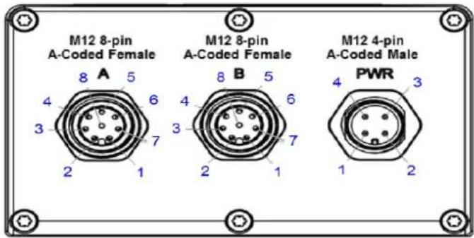
Figure 3.1 WISE-S600 Pin Out
Table 3.1: I/O Pin Assignment
| Model Name | M12 Cable WISE-S672 WISE-S614 WISE-S615 WISE-S617 | |||||
| Pin Number | ||||||
| PCB P/N | 4Pin: 1700028162-018Pin: 1700028163-01 | 19A3DC7200-01 | 19A3DB1402-01 | 19A3DC1500-01 | 19A3DC1700-01 | |
| Version A101-1 (M/P) A101-3 (M/P) A101-1 (ES1) | A101-1 (ES1) | |||||
| A | 1 | White | DI 0 | DI 0 | RTD0+ | AI 0+ |
| 2 | Brown | DI 1 | DI 1 | RTD0- | AI 0- | |
| 3 | Green | DI 2 | DI 2 | RTD0 COM | +12V Out0 | |
| 4 | Yellow | DI 3 | DI 3 | NC | +12V Out GND | |
| 5 | Gray | DI 4 | NC | RTD1+ | AI 1+ | |
| 6 | Pink | DI 5 | NC | RTD1- | AI 1- | |
| 7 | Blue | NC | NC | RTD1 COM | +12V Out1 | |
| 8 | Red | DI COM | DI COM | NC | +12V Out GND | |
| B | 1 | White | DATA0- | AI 0+ | RTD2+ | DI 0 |
| 2 | Brown | DATA0+ | AI 0- | RTD2- | DI 1 | |
| 3 | Green | RS-232 TX | AI 1+ | RTD2 COM | DI COM | |
| 4 | Yellow | RS-232 RX | AI 1- | NC | DO 0 | |
| 5 | Gray | DATA1- | AI 2+ | RTD3+ | DO GND | |
| 6 | Pink | DATA1+ | AI 2- | RTD3- | RS-485 D+ | |
| 7 | Blue | NC | AI 3+ | RTD3 COM | RS-485 D- | |
| 8 | Red | RS-232 GND | AI 3- | NC | RS-485 GND | |
| PWR | 1 | Brown | +VS | +VS | +VS | +VS |
| 2 | White | -VS | -VS | -VS | -VS | |
| 3 | Blue | SP+ | SP+ | SP+ | SP+ | |
| 4 | Black | NC | SP- | SP- | SP- | |
| Gray (NC) | ||||||
3.7 Pin Assignment of WISE-S600T I/O Module with Terminal Block Connectors
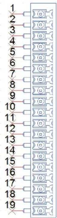
| Update Date | 2020/3/16 | ||
| Model Name | WISE-S614T | WISE-S617T | WISE-S615T |
| PCB P/N | 19A3DC1410-01 | 19A3DC1710-01 | 19A3DC1710-01 |
| Version | A101-1 | A101-1 | A101-1 |
| Power In | Line Power, Panel in | Line Power, Panel in | Line Power, Panel in |
| I/O Description | 4*AI, 4*DI | 2*DI, 1*DO, 1*RS-485, 2*AI, 2*12V_output | 4*RTD |
| 1 | DI 0 | AI 0+ | RTD 0+ |
| 2 | DI 1 | AI 0- | RTD 0- |
| 3 | DI 2 | AI 1+ | COM 0 |
| 4 | DI 3 | AI 1- | RTD 1+ |
| 5 | DI COM | VOUT 0 | RTD 1- |
| 6 | AI 0+ | VOUT GND | COM 1 |
| 7 | AI 0- | VOUT 1 | RTD 2+ |
| 8 | AI 1+ | VOUT GND | RTD 2- |
| 9 | AI 1- | DO 0 | COM 2 |
| 10 | AI 2+ | DO GND | RTD 3+ |
| 11 | AI 2- | DI 0 | RTD 3- |
| 12 | AI 3+ | DI 1 | COM 3 |
| 13 | AI 3- | DI COM | NC |
| 14 | NC | DATA+ | NC |
| 15 | NC | DATA- | NC |
| 16 | NC | GND | NC |
| 17 | Panel In | Panel In | Panel In |
| 18 | +VS | +VS | +VS |
| 19 | -VS | -VS | -VS |
3.8 Application Wiring of WISE-S600 I/O Module with M12 Connectors
3.8.1 WISE-S614 I/O Application Wiring
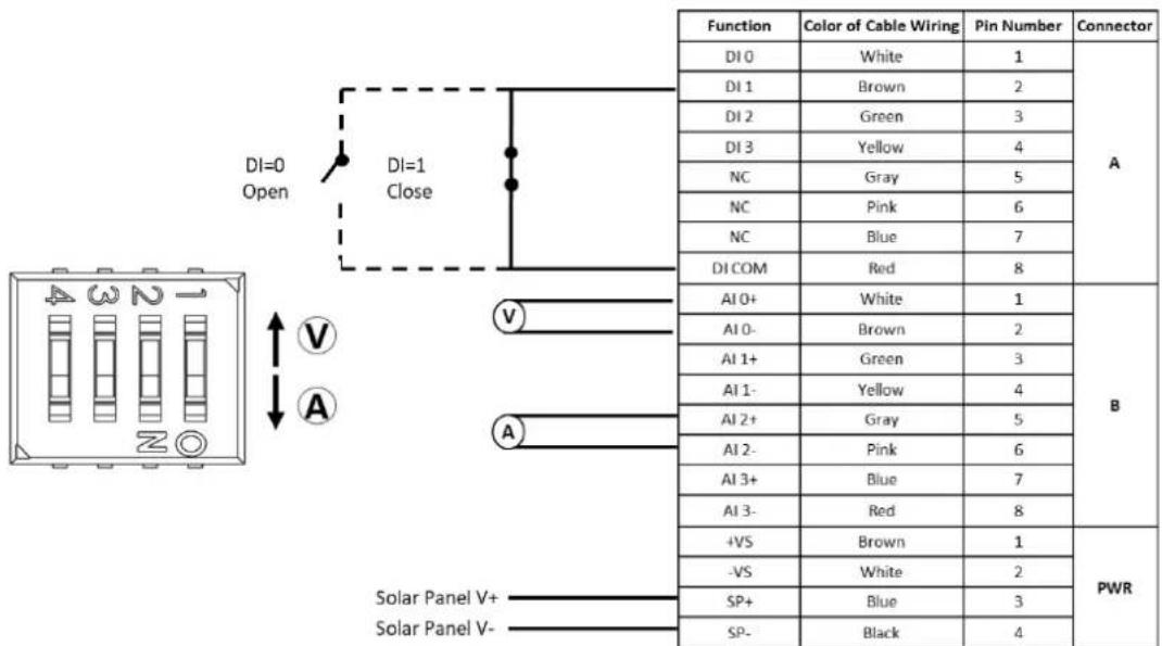
Figure 3.2 WISE-S614 I/O Application Wiring
3.8.2 WISE-S615 I/O Application Wiring
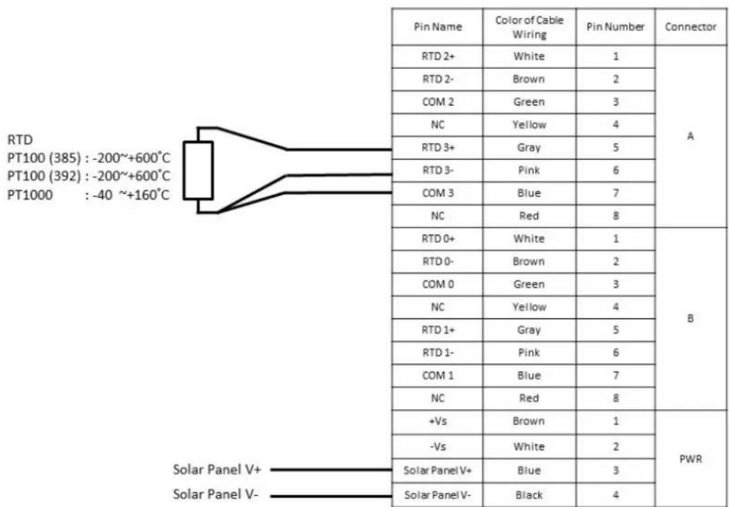
Figure 3.3 WISE-S615 I/O Application Wiring
3.8.3 WISE-S617 I/O Application Wiring
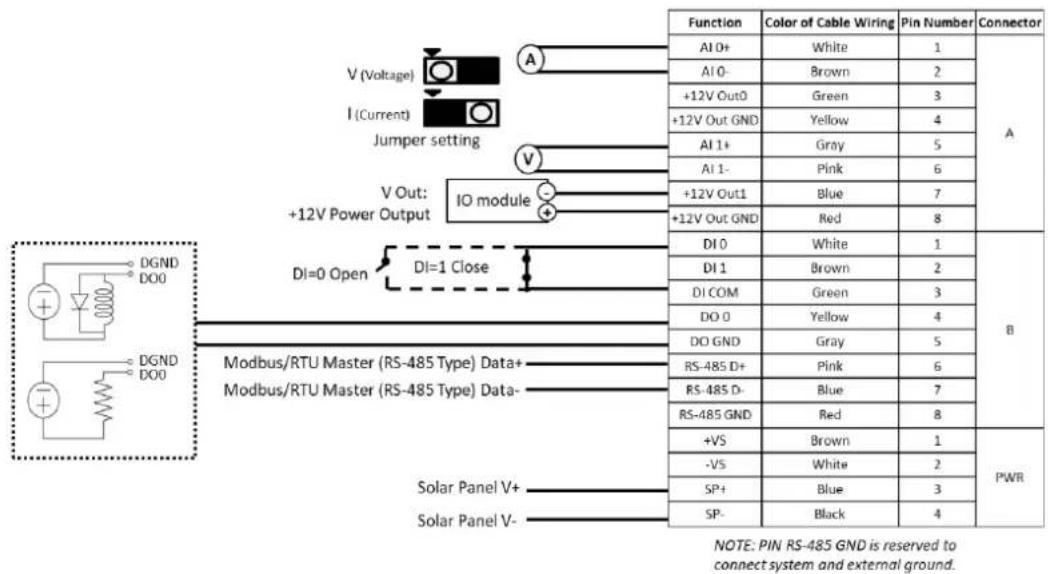
Figure 3.4 WISE-S617 I/O Application Wiring Diagram
3.8.4 WISE-S672 Application Wiring
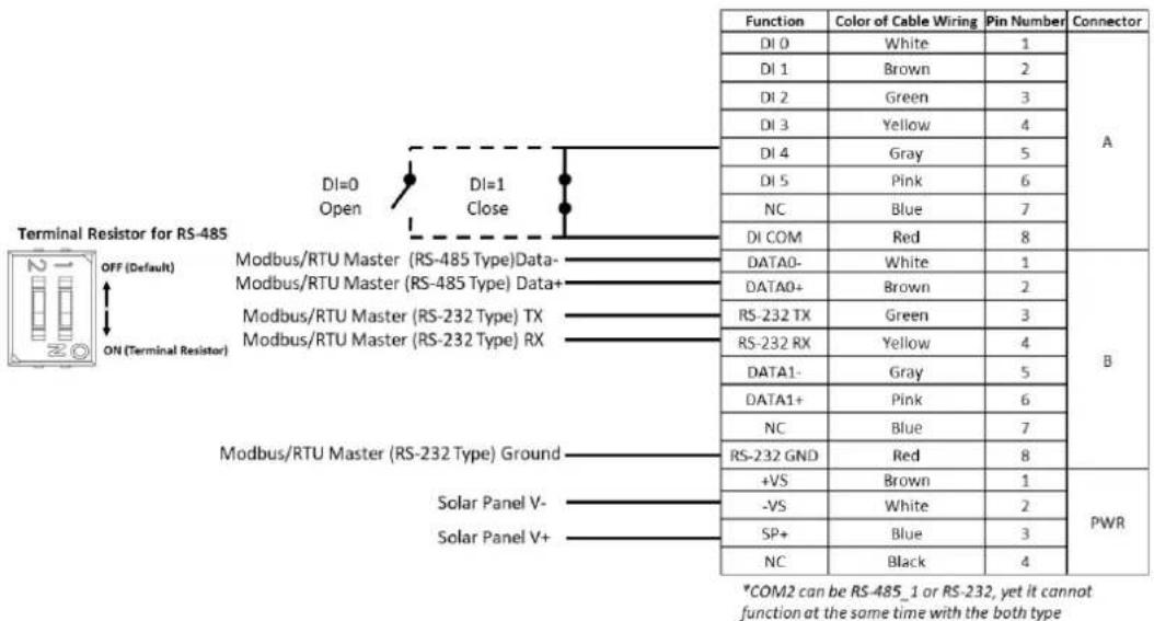
Figure 3.5 WISE-S672 Application Wiring Diagram
3.9 Application Wiring of WISE-S600T I/O Module with Terminal Block
3.9.1 WISE-S614T I/O Application Wiring
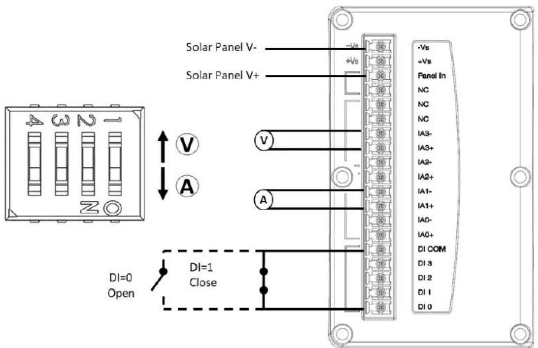
Figure 3.6 WISE-S614T I/O Application Wiring Diagram
3.9.2 WISE-S617T I/O Application Wiring
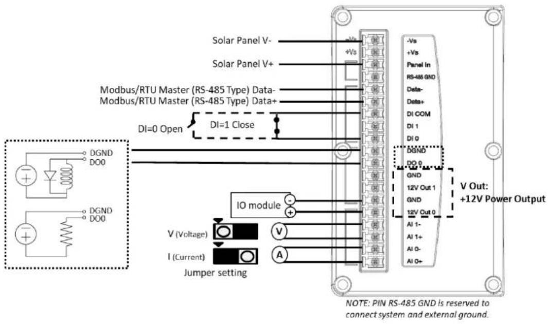
Figure 3.7 WISE-S617T I/O Application Wiring Diagram
3.10 Power Supply Wiring
WISE-4610 modules are designed to support a standard unregulated 24- V_DC industrial power supply. However, they can also accept 10 \~ 50 V_DC input with a peak-to-peak power ripple of 200 mV. The immediate ripple voltage should be maintained at 10 \~ 50 V_DC . The screw terminals labeled “+Vs” and “-Vs” are for the power supply wiring. Refer to Section 3.6 “I/O Pin Assignment” for more details.
3.11 Block Diagram
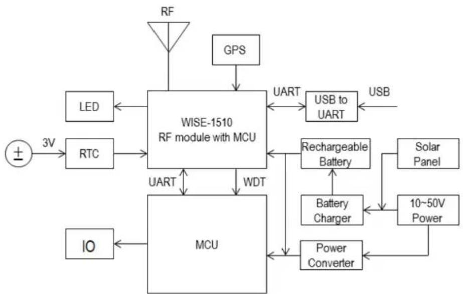
flowchart
graph TD
    RF["RF"] -->|Signal| WISE-1510["WISE-1510 RF module with MCU"]
    GPS["GPS"] -->|Signal| WISE-1510
    LED["LED"] -->|3V| RTC["RTC"]
    RTC -->|UART| MCU["MCU"]
    IO["IO"] --> MCU
    WISE-1510 -->|UART| USB1["USB to UART"]
    WISE-1510 -->|WDT| Rechargeable["Battery"]
    Rechargeable --> BatteryCharger["Battery Charger"]
    Rechargeable --> PowerConverter["Power Converter"]
    USB1 --> USB2["USB"]
    USB2 --> RechargeableBattery["Rechargeable Battery"]
    RechargeableBattery --> SolarPanel["Solar Panel"]
    RechargeableBattery --> 10~50VPower["10~50V Power"]
Figure 3.8 WISE-4610 Block Diagram
3.12 Configuration Interface
■ Interface: USB virtual COM port
Connector: Micro-B USB
USB Chipset: Silicon Labs CP210x
Driver: CP210x USB-to-UART bridge VCP drivers
Chapter 4
Software Functions
4.1 System Structure
LoRaWAN (Long Range Wide Area Network) system structure consists of several key components that work together to enable long-range communication between IoT devices. Here's an overview:
1. End Devices (WISE-4610)
■ Function: WISE-4610 Industrial Wireless I/O solution can connect to any kinds of sensors or meters to collect data, such as flow, pressure, level, energy usage for different kinds of applications
■ Communication: End devices use LoRa modulation to send data to gateways.
2. Gateways (WISE-6610)
■ Function: Gateways act as a bridge between the end devices and the network server. They receive LoRa-modulated signals from the end devices and forward them to the network server via a standard IP connection (e.g., Ethernet or cellular).
- Communication: Gateways are typically connected to the network server through a high-bandwidth connection, allowing them to handle multiple data streams from various devices simultaneously.
3. Network Server (Embedded in WISE-6610)
Function: The network server manages the network, ensuring that data is correctly routed between end devices and the application server. It handles tasks such as:
De-duplication: Ensuring only one copy of a message is processed if multiple gateways receive the same message.
■ Security: Managing encryption keys and ensuring secure data transmission.
■ Device Management: Tracking all devices, their status, and configuration.
4. Application Server
■ Function: The application server processes data received from the end devices via the network server. It interprets this data, making it available for applications, dashboards, or triggering other actions (e.g., sending alerts).
■ Communication: The application server communicates with the network server to receive data and can send commands back to the devices if necessary.
This structure enables LoRaWAN to provide long-range, low-power communication, making it ideal for various IoT applications, including smart cities, agriculture, and industrial monitoring.
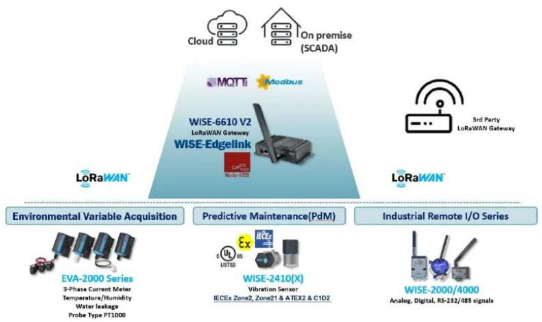
flowchart
graph TD
    A["Cloud"] --> B["On premise (SCADA)"]
    C["Modbus"] --> D["WISE-6610 V2 LoRaWAN Gateway"]
    E["3rd Party LoRaWAN Gateway"] --> F["LoRaWAN"]
    G["Environmental Variable Acquisition"] --> H["EVA-2000 Series"]
    H --> I["3-Phase Current Meter Temperature/Humidity Water leakage Probe Type PT1000"]
    J["Predictive Maintenance(PdM)"] --> K["WISE-2410(X) Vibration Sensor"]
    L["Industrial Remote I/O Series"] --> M["WISE-2000/4000 Analog, Digital, RS-232/485 signals"]
4.2 Interface Design
4.2.1 LoRaWAN Functions
WISE-4610 can be configured via WISE-Studio to establish a LoRaWAN.
| Table 4.1: LoRaWAN Functions | |
| Item Description | |
| Device Operating Mode | LoRaWAN |
| Device Class | (Default: 1)1: Class A3: Class C |
| Activation Mode | (Default: 2)1: OTAA (Over-The-Air Activation)2: ABP (Activation By Personalization) |
| Port Field (FPort) | FPort values 1.223 (0x01.0xDF) are application-specific and any received frames with such an FPort SHALL be made available to the application layer by the LoRaWAN implementation. |
| Data Message Confirmed | 1: Configure the module to send data message confirmations that must be acknowledged by the receiver.0: Unconfirmed data messages. |
| Application Identifier (AppEUI), if OTAA | AppEUI is a global application ID in IEEE EUI64 address space that uniquely identifies the entity able to process the JoinReq frame. AppEUI is stored in the end-device before the activation procedure is executed.(Length: 8 bytes) |
| Application Key (AppKey), if OTAA | AppKey is an AES-128 root key specific to the end-device. Whenever an end-device joins a network via over-the-air activation, the AppKey is used to derive the NwkSKey and AppSKey session keys specific to that end-device for encrypting and verifying the network communication and application data.(Length: 16 bytes) |
| Network Session Key (NwkSkey), if ABP | The NwkSKey is a network session key specific for the end-device. It is used by both the network server and the end-device to calculate and verify the MIC (message integrity code) of all data messages to ensure data integrity. It is also used to encrypt and decrypt the payload field of MAC-only data messages.(Length: 16 bytes) |
| Application Session Key (AppSKey), if ABP | The AppSKey is an application session key specific to the end-device. It is used by both the application server and the end-device to encrypt and decrypt the payload field of application-specific data messages.(Length: 16 bytes) |
Table 4.2: Configuration Parameters for LoRaWAN
| OTAA ABP | |
| Globally Unique End-Device Identifier (DevEUI) V | |
| Device Addres (DevAddr) V | |
| Application Identifier (AppEUI) V | |
| Application key (AppKey) V | |
| Network Session Key (NwkSkey) V | |
| Application Session Key (AppSKey) V | |
4.2.2 Positioning
4.2.2.1 General Description
WISE-4610 accesses the u-blox EVA-M8M-0 GNSS module via the I2C interface. This GNSS module can provide geolocation and time information.
The features of EVA-M8M are listed below:
Table 4.3: Features
| Receiver Type | 72-channel u-blox M8 engineGPS/QZSS L1 C/A, GLONASS L10F,BeiDou B1SBAS L1 C/A: WAAS, EGNOS, MSASGalileo-ready E1B/C |
| Maximum Navigation Update Rate | Single GNSS: Up to 18 HzConcurrent GNSS: Up to 10 Hz |
| Accuracy | Position: 2.5 m CEPSBAS: 2.0 m CEP |
| Acquisition | Cold starts: 27 sAided starts: 4 sReacquisition: 1 s |
| Sensitivity | Tracking and navigation: -164 dBmCold starts: -147 dBmHot starts: -156 dBm |
| Assistance GNSS | AssistNow OnlineAssistNow OfflineAssistNow autonomousOMA SUPL and 3GPP compliant |
■ Measurement Data
The data below is available from the GNSS module:
Table 4.4: Measurement Data
| Values Description | ||
| UTC Time | 2017~ Year | |
| 1 ~ 12 Month | ||
| 1 ~ 31 Day | ||
| 0 ~ 23 Hour | ||
| 0 ~ 59 Minute | ||
| 0 ~ 59 Second | ||
| Position | Longitude | (+ - *10^-7 degree), a minus sign if south of the equator |
| Latitude | (+ - *10^-7 degree), a minus sign if west of the prime meridian | |
| Altitude | (*10^-3 m) height above mean sea level | |
| Speed | (*10^-3 km/hr) ground speed | |
| Number of satellites | Satellites used for navigation | |
Table 4.5: Configurations
| Item Description | |
| Positioning Enable/Disable | Enable or disable the GNSS module. (Default: Disable) |
| Position Update Period | Time between two position fix attempts (15 sec ~ 1 day, unit: second)(Default: 1 hr) |
| Select Permissible GNSS System | Specify which GNSS signals should be processed |
| Value GNSS combination | |
| 0 (Reserved) | |
| 1 GPS + GLONASS (default) | |
| 2 GPS + Galileo | |
| 3 Galileo + GLONASS | |
| 4 GPS + Galileo + GLONASS | |
| 5 GPS + BeiDou | |
| 6 Galileo + BeiDou | |
| 7 GPS + Galileo + BeiDou | |
| 8 GLONASS + BeiDou | |
| *If GPS is enabled, SBAS and QZSS will also be enabled by default. | |
4.2.3 LED Indicator Behaviors
All LED indicators will turn OFF automatically after 15 seconds when the module is using battery power.
Table 4.6: LED Indicator Behaviors
| LED Color State Description | |||
| Status Green | Fast blink(0.2 sec ON, 0.3 sec OFF) | Waiting for connection or connecting | |
| Slow blink(0.2 sec ON, 1.8 sec OFF) | Connecting and operating normally | ||
| Error Red | Fast blink(0.2 sec ON, 0.8 sec OFF) | Application errors. (*Note 1)■ Network registration timeout■ I/O Error■ FW error | |
| Slow blink(0.2 sec ON, 2.8 sec OFF) | ■ Low battery voltage (v <= 20%)■ Low RTC battery voltage■ Battery internal short is detected | ||
| Off No error | |||
| RF RX | Green | On (0.2 sec ON) | Received data from Gateway |
| Off Idle | |||
| RF TX Yellow | On Sending data to gateway | ||
| Off Idle | |||
| Signal Strength | 4 Green | On(if pressing the membrane button) | Main battery capacity■ All OFF - V <= 20%■ 1 ON - 20% < V < 40%■ 2 ON - 40% <= V < 60%■ 3 ON - 60% <= V < 80%■ 4 ON - V >= 80% |
*Note 1
Table 4.7:
| Error LED | Signal LEDs | Description | |||
| 1st (poor) | 2nd (Okay) | 3rd (Good) | 4th (Full) | ||
| Fast Blink | OFF OFF | OFF Fast Blink RF related Error | |||
| OFF OFF | Fast Blink OFF I/O Error | ||||
| OFF OFF | OFF OFF FW error | ||||
| Slow Blink | OFF OFF | OFF OFF Battery related Error | |||
| OFF OFF | OFF OFF | OFF No error | |||
4.2.4 Battery Charging
The battery IC serves as a gauge for estimating the remaining battery capacity.
Table 4.8:
| Items Values Description | |
| Remaining Battery Capacity 0 ~ 100% | An unsigned integer value of the predicted remaining battery capacity expressed as a percentage of full-charge capacity, with a range of 0 to 100%. |
| Cycle Count 0 ~ 65535 | An unsigned integer value of the number of cycles the battery has undergone |
| Temperature °C | An unsigned integer value of the battery temperature in units of 0.01 °C.* Temperature: 0x06/0x07 command used. It should be the external thermistor temperature. |
Table 4.9:
| Operating Status | Flags | Flag Bit Definitions | |
| Bit Content | |||
| 15 OTC | |||
| 14 OTD | |||
| 13 BATHI | |||
| 12 BATLOW | |||
| 11 CHG_INH | |||
| 10 RSVD | |||
| 9 | FC | ||
| 8 CHG | |||
| 7 OCVTAKEN | |||
| 6 ISD | |||
| 5 TDD | |||
| 4 HW1 | |||
| 3 HW0 | |||
| 2 SOC1 | |||
| 1 SOCF | |||
| 0 DSG | |||
| OTC = Over Temperature in Charge condition detected. True when set. OTD = Over Temperature in Discharge condition detected. True when set. BATHI = Battery High bit, indicating a high battery voltage condition. BATLOW = Battery Low bit, indicating a low battery voltage condition. CHG_INH = Charge Inhibit indicates the temperature is outside the range [Charge Inhibit Temp Low, Charge Inhibit Temp High]. True when set. FC = Fully charged condition reached (RMFCC = 1; Set. FC_Set% = -1% when RMFCC = 0). True when set. CHG = (Fast) charging allowed. True when set. OCVTAKEN = Cleared when switched to Relax mode, and set to 1 when OCV measurement is performed in Relax mode. ISD = Internal Short is detected. True when set. TDD = Tab Disconnect is detected. True when set. HW [1:0] Device Identification. Default is 01. SOC1 = State-of-Charge Threshold 1 (SOC1 Set) reached. True when set. SOCF = State-of-Charge Threshold Final (SOCF Set%) reached. True when set. DSG = Discharging detected. True when set. | |||
Battery Events
Table 4.10: Battery Events
| Events Condition | Error LED(Slow Blink) | |
| Low voltage Remaining battery capacity <= 20% V | ||
| Over Temperature in Charge condition detected | Battery temperature < 0 °C or >60 °C | |
| Over Temperature in Discharge condition detected | OTD flag of Operating Status set | |
| Internal Short detected ISD flag of Operating Status set V | ||
| Fully charged condition reached | FC flag of Operating Status set | |
■ Battery Temperature and Charging
Table 4.11: Battery Temperature and Charging
| Battery Temp. T (°C) Battery Level % Charging | |||
| 1 T < 0 - | Stop charging | ||
| 2 | 0≤T≤45 | - | Allow charging |
| 3 | 45 < T ≤ 60 | >10% | Stop charging |
| ≤10% | Charge to 20% only | ||
| 4 T >60 | - | Stop charging | |
4.2.5 Membrane Button
Refer to Section 4.2.3 "LED Indicator Behaviors" for detailed information regarding the membrane button functionality:
In the "DC Power Only" or "DC Power and Battery" modes, when WISE-4610 is powered via the power cable:
- The LED indicators are turned OFF as the default setting.
- To check the battery capacity, press the membrane button to light up the battery capacity indicator.
- Press the membrane button again to turn OFF the LED indicators and revert to State 1.
- If the power cable is removed and WISE-4610 is powered by the battery, the module will enter "Battery Power Only" mode.
In "Battery Power Only" mode:
- The LED indicators are turned OFF as the default setting. The Status/Error/Rx/Tx/COM LEDs will light up for 15 seconds only.
- In State 1, all LED indicators will automatically turn OFF after 15 seconds to save power.
- In State 1, when the membrane button is pressed, all LED indicators, including the four battery capacity indicators, will light up. The indicators will automatically turn OFF after 15 seconds.
- In State 3, press the membrane button again to turn OFF the LED indicators.
- When all LED indicators are not illuminated, press the membrane button again to revert to State 1.
- When connected to the power supply cable, WISE-4610 will enter either the "DC Power Only" or "DC Power and Battery" modes.
4.2.6 Multiple Power Sources
WISE-4610 is compatible with three sources of power: batteries, DC power, and solar panels. The power source detection, power fail (remove cable and solar power), low-battery, and suspend LEDs will vary depending on the power source:
Low-Battery Indicator - When the remaining battery capacity is 20% or less, the low-battery LED will blink slowly.
- Low-Battery Suspend - When the remaining battery capacity is 10% or less, module operations will be suspended.
| Table 4.12: | |||||||
| Power Combination Module Features | |||||||
| DC Power | Solar Panel | Battery | Power source detection error LED Suspend | Power fail (remove cable and solar panel) | Low battery | ||
| Switch E | |||||||
| Y | Y | Y | ON | Cable, battery | No PF signal, system running | Slow blink if ≤20% | No |
| OFF PF | |||||||
| N Cable PF | |||||||
| N | Y | ON | Cable, bat-tery | No PF signal, system running | Slow blink if ≤20% | No | |
| OFF PF | |||||||
| N Cable PF | |||||||
| N | Y | Y | ON | Solar panel, battery | No PF signal, system running | Slow blink if ≤20% | No |
| OFF PF | |||||||
| N Solar panel | PF | ||||||
| N | Y | ON Battery | No PF signal (battery cannot be removed) | Slow blink if ≤20% | Suspend if ≤10% | ||
| OFF | Module is not working | ||||||
| N | |||||||
| Table 4.13: | ||||
| Power Cable (DC/Panel) | Battery Power | Action | Keep counter values | |
| Switch | ||||
| Y | N | Remove power cable | Yes | |
| Y | Y | ON | Remove power cable | Based on battery level |
| OFF | No | |||
| N | Y | ON | Switch ON→OFF | No |
4.3 Connection Setting on WISE-4610
- Configure the WISE-4610 module using WISE-Studio through a USB port.
4.3.1 Configure WISE-4610 by Using WISE-Studio
4.3.1.1 Minimum System Requirements
The minimum system requirements for WISE-Studio are as follows:
■ Microsoft Windows 7 or later
■ Microsoft .NET framework 3.5 or later
■ Internet Explorer 10 or later
4.3.1.2 Installing WISE-Studio
The latest version of WISE-Studio is available on the Advantech support website http://support.advantech.com/. To install the software, download the installation file and execute it locally.
4.3.1.3 Introduction to WISE-Studio
WISE-Studio is a tool for configuring WISE modules. The software provides a web-based interface that is similar for different models. For WISE modules configured via Ethernet, LAN, or WLAN, WISE-Studio enables communication with the WISE module's internal web server. For modules configured via USB, WISE-Studio executes a web server on the computer installed with the software. The web server then uses the USB interface to communicate with the WISE module. The module information can be accessed via the embedded web page or a web browsers.
Communication Box
In this box, there are several communication interfaces for configuring various WISE modules. The WISE-4610 series uses the USB serial interface for configuration.
Refresh: Pressing this button refreshes the USB serial interface.
USB-Serial: This block is for connecting to a WISE module via USB. The available USB serial port number will be shown here. Click Go to Configuration to connect the USB COM port.
USB-Serial Configuration Page
After clicking Go to Configuration, all available USB COM ports will be displayed. Choose the COM port to configure and click Connect to open the Configuration page. Users can also click Open in Browser to use your default browser to configure the WISE module (IE is the default browser embedded in WISE-Studio).
4.3.1.4 Information Page
Module Information
This page displays the name of the module and related information. Click Go to Configuration to view or change the settings.
Model Name: Model of WISE module
Customized Name/UUID: Refer to the model name and UUID of the module.
The default UUID is a combination of the model name and IMEI. Users can modify this value.
Location Information: The module location is provided here.
Description: Any comments about the module can be displayed here.
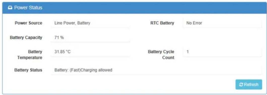
Power Status displays the power source and battery status.
Device Information lists the module firmware and web page version.
On this page, users can obtain the WISE module coordinates.

Configuration
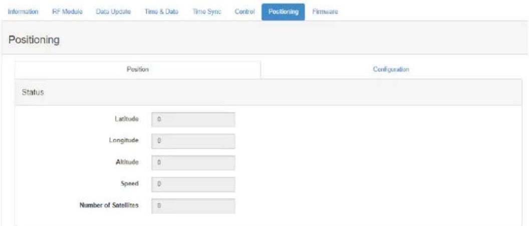
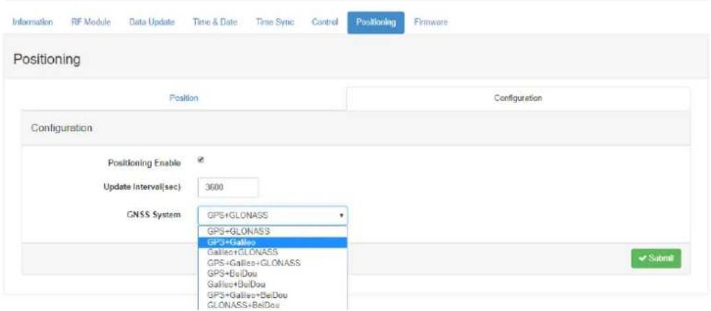
The WISE-4610 module is equipped with GPS. The options on this page allow users to enable/disable GPS positioning. To save power, GPS is disabled by default. Moreover, users can configure the specific update interval.
As shown below, the GNSS System field features a dropdown menu with different GPS system combination options. Users can select the system combination according to their usage requirements.

Configuration
4.3.1.5 I/O Status Configuration
Digital Input
Status
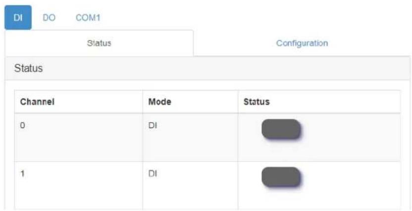
The value of all digital input channels can be determined from the LED indicators on the DI tab (green LED = logic high; grey LED = logic low).

IO Status
Configuration
The digital input channels support several operation modes and can be configured from this page.
■ Channel: Select the channel to be configured.
Tag Name: Each channel can be given a name for identification.
■ Mode: This item allows users to configure the operating mode for each channel. Channels can also be disabled/enabled to improve the overall performance. After a channel has been configured, click Submit at the bottom of this page to implement the changes.
■ Channel Mask: Each channel can be disabled individually to reduce data communication traffic.
■ Refresh: This item allows users to refresh the system configuration settings.
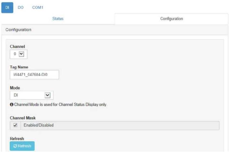
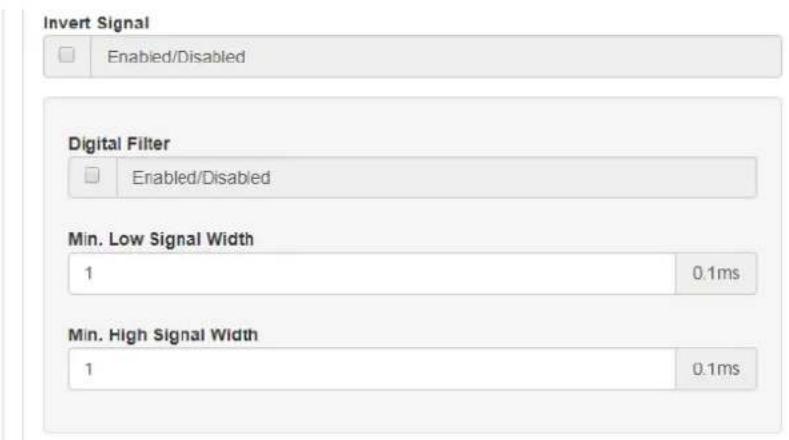
Invert Signal: WISE digital input channels support inverted digital input status. To enable/disable this function, click the Invert Signal check box on the Configuration page.
Digital Filter: Digital input channels have a digital filter that can remove high-frequency noise. The filter can be enabled/disabled by clicking the Digital Filter check box. When the filter is enabled, the minimum acceptable signal width can be defined in the Min. Low Signal Width and Min. High Signal Width fields (increment: 0.1 ms).
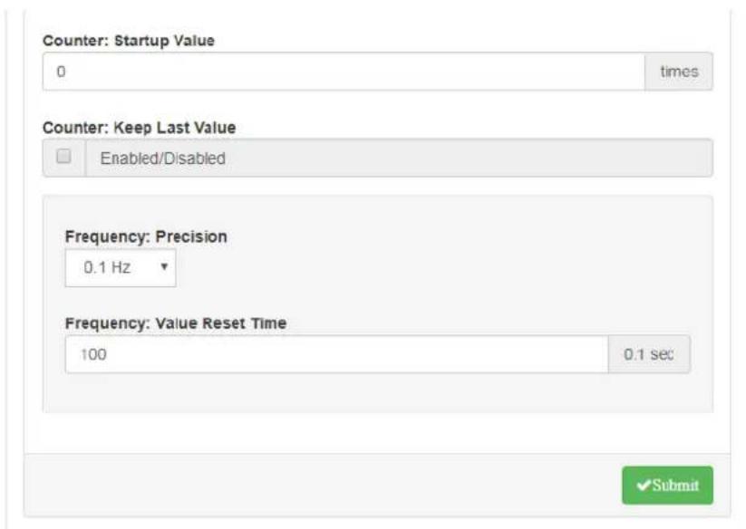
Counter: When counter mode is selected for a given channel, the number of pulses in the digital signal from that channel are counted and recorded to the register. On the Status page, the current count value of the selected channel is displayed in the Counter Value field. The counter can be started/stopped by pressing Start/Stop. The counter can be reset (the value stored in the register will be reset to the default, which is zero) by clicking Reset. The predefined startup value is the value shown in the Counter value field. When this is reset, either by pressing Reset on the Status page or by issuing a command, the default settings will be restored (the default value for this field is zero). If Keep Last Value is enabled, the last counter value will be retained in the register when the module is powered OFF. When the module is powered ON, the counter will continue to count from that value. When this function is disabled, powering off the module will cause the counter to be reset and the count value in the register to be reset to zero.
Frequency: For pure digital input channels, WISE modules support frequency mode, which calculates the frequency of the digital input signal of the selected channel. The frequency value will be displayed in the Frequency value field on the DI Status page. The Precision settings can be configured to specify the frequency for different input ranges. The Value Reset Time function allows users to specify when the frequency value is reset to zero if the pulse bandwidth is greater than expected.
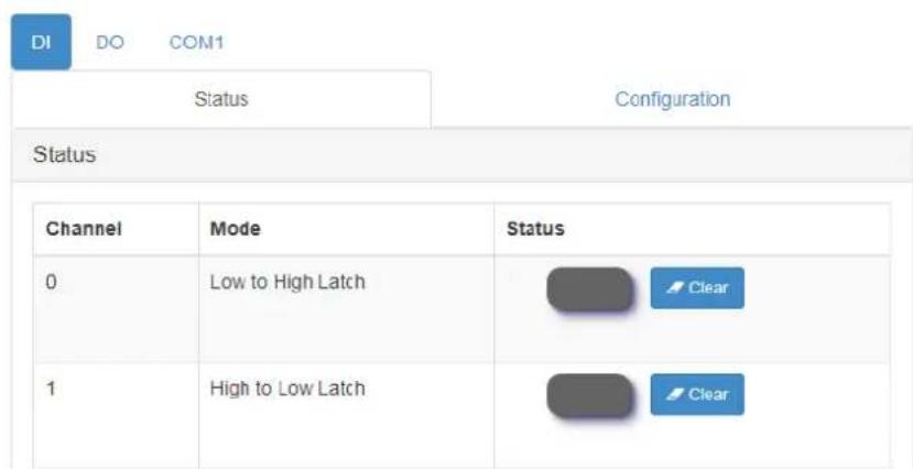
Low-to-High Latch: Under low-to-high latch mode, once a digital input channel detects that the logic level has changed from low to high, the logic status will remain as "logic high" until the latch is cleared manually, which will return the logic status to "logic low". The logic status can be determined via the latch status LED included on the DI Status page. Clear the latch by clicking Clear.
- High-to-Low Latch: Under high-to-low latch mode, once a digital input channel detects that the logic level has changed from high to low, the logic status will remain as “logic low” until the latch is cleared manually, which will return the logic status to “logic high”. The logic status can be determined via the latch status LED included on the DI Status page. Clear the latch by clicking Clear.
IO Status
COM1 (RS-485 Port)
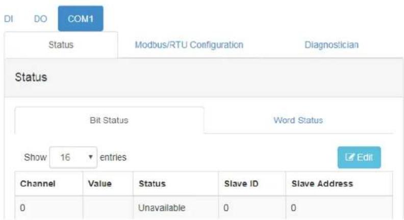
WISE-4610 features one RS-485 port for Modbus gateway functionality. This port can be used to poll data from RS-485 Modbus/RTU slave devices, such as Advantech's ADAM-4000 or ADAM-5000/485 series devices.
Status
Navigate to the COM1 tab to check the status or configure the RS-485 Modbus master function. A total of 32 Modbus slave addresses can be mapped as the WISE module I/O. These 32 addresses can be coils or registers; coils will be mapped as extension bits of the WISE module, and registers will be mapped as extension words of the WISE module. In the COM1 status tab, the bits and words are shown on individual pages.
■ Channel: Indicates the number of bits. A maximum of 32 bits can be displayed, but less than 32 coils can be mapped as bits. The empty bits are invalid. The same applies to words, which may also have empty channels.
■ Value: This shows the value polled from mapped addresses.
■ Status: This shows the status of each bit or word. If a channel is empty or has not been mapped to a Modbus slave address, the status will be "Unavailable".
■ Slave ID: This is the Modbus slave ID of RS-485 Modbus slave devices.
■ Slave Address: This is the address of a bit or word from an RS-485 Modbus slave device.
For a writable bit or word, users can click Edit to switch to edit mode to change the value. Then click Apply to write the Modbus addresses individually.
IO Status
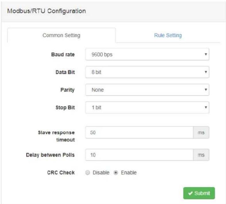
Modbus Configuration - Common Settings Tab
The options on this tab allow users to configure the RS-485 port parameters.
Baud Rate: 1200, 2400, 4800, 9600, 19200, 38400, 57600, 115200 bps
Data Bit: 7, 8
■ Stop Bit: 1, 2
Parity: None, Odd, Even
■ Slave Response Timeout: This item allows users to specify the response time for Modbus slaves.
■ Delay Between Polls: This item allows users to set the delay time between each Modbus instruction.
CRC Check: This item allows users to set the CRC check to ignore Modbus CRC errors.
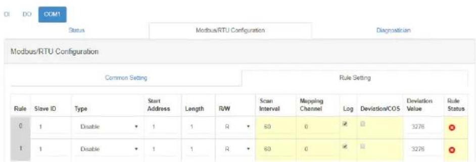
Modbus Configuration - Rule Setting Tab
The items on this tab allow users to configure the Modbus address of end devices to be polled.
Rule: Each COM port can support a maximum of 8 rules. Each rule can be for a different slave device. This means a maximum 8 of devices can be connected to the COM port. Alternatively, all the rules can be used for polling different addresses on the same slave device.
- Slave ID: Each slave device connected to the RS-485 port has a unique slave ID. This item is the slave address of the Modbus devices connected to the WISE module.
Type: This device supports Modbus data types: 01 Coil Status (0x), 02 Input Status (1x), 03 Holding Registers (4x), and 04 Input Registers (3x). After one of the types has been configured in the rule, the rule will be enabled and the COM port will start polling after the configuration has been implemented.
- Start Address: Enter the first address number to be polled. The address base is 1. To poll the first address of a holding register (i.e., 40001), simply input the number "1" (users do not need to input the entire address "40001").
Length: Input the length of the address to be polled in this rule. For example, to poll 40001 \~ 40008, set the length as "8". Because each COM port can poll a maximum of 32 addresses, the maximum length is 32, and the total number of all rules should not exceed 32.
R/W: This item allows users to set whether the address in this rule is read or written. For coil statuses and holding registers, users can configure these addresses as read-only or write-only to reduce the polling effort.
- Scan Interval (unit: s): This item allows users to set the scan interval for the COM port to poll Modbus slave devices. The COM port optimizes the scan interval according to the setting configuration. However, the read scan interval may depend on factors such as the Baud rate, slave device response time, and delay between polls. See the Diagnostician page to check the real response time as a reference for the scan interval value.
Mapping Channel: When the Modbus address of slave devices is configured in each rule, these addresses are also mapped to the WISE module. the coils and registers of Modbus slave devices are mapped as bits for RESTful web service. There are 32 continuous channels of bits and another 32 continuous channels of words that can be mapped. Ensure that the channels for each rule do not overlap.
Log: This item allows users to set whether the data polled from this rule is logged in the data logger.
■ Deviation/Change of Status (COS): When this item is enabled, the difference between the current poll and last poll values can trigger a deviation/COS (change of state) for push data or log data.
Rule Status: The web configuration interface will check whether the rule settings have any overlap or conflict. Rules can be enabled/disabled by setting the Type value. Enabled rules will be denoted with a green icon. The system will prompt users to confirm the submission of rules.
Note! After configuring the rules, click Submit to implement them.

Note! After changing the rule configurations, the data logger is cleared of all data to accommodate the new data structure under the new configuration.
Note! Move the mouse cursor over the table title rows to view tips.

IO Status
Diagnostician
Because every device has a different response time, the WISE-4610 module supports a diagnostics function for testing the response time of each rule. This is intended to reduce the scan interval. Users can refer to the response time shown on this page when configuring the Scan Interval in the Rule Setting pages. The test results shown on this page can be reset by clicking Reset Response Time.
IO Status
| Modbus/RTU Slave Response Time | ||||
| Rule | Current Response Time(ms) | Max Response Time(ms) | Min Response Time(ms) | Status |
| 0 | 0 | 0 | 65535 | Unavailable |
| 1 | 0 | 0 | 65535 | Unavailable |
4.3.1.6 System Configuration
Time & Date
WISE modules have a built-in RTC that allows users to view the current time, set the time zone, and adjust the time by pressing Click Me to read the time from host devices.
Control
- Restore to Default: This item allows users to clear the system configuration and restore all default settings.
System Restart: This item reboots the module for a system restart.
Firmware
To update the firmware, go to the Firmware page in System Configuration and click the update file. The latest official firmware releases are available on the Advantech support website (http://support.advantech.com/). Users can also upload or export the configuration file.
Appendix A
Modbus Table with WISE-4610
Table A.1: WISE-4610-S617 (for WISE-6610 LoRaWAN GW)
AI 2 DI 2 DO 1 Serial Port 1
| Address 0X Ch Description Attribute Address 4X Ch Description Attribute | |||||||
| 00001 | 0 | DI Value | Read | 40017~40018 | 0 | Counter/ Frequency Value | Read |
| 00002 | 1 | Read | 40019~40020 | 1 | Read | ||
| 00033 | 0 | Counter Start (1)/Stop(0) | R/W | 40301 | All | DI Value | Read |
| 00034 | 1 | R/W | |||||
| 00041 | 0 | Clear Counter (1) | Write | ||||
| 00042 | 1 | Write | |||||
| 00049 | 0 | Clear Overflow | R/W | ||||
| 00050 | 1 | R/W | |||||
| 00057 | 0 | DI L2H Latch Status | R/W | ||||
| 00058 | 1 | R/W | |||||
| 00065 | 0 | DI H2L Latch Status | R/W | ||||
| 00066 | 1 | R/W | |||||
Address 0X Ch Description Attribute Address 4X Ch Description Attribute
| 00017 | 0 | DO Value | R/W | 40303 | All | DO Value | R/W |
| Address 0X Ch Description Attribute Address 4X Ch Description Attribute | |||||||
| 00101 | 0 | ResetHistoricalMax. AlValue | Write | 40001 | 0 | AI Value | Read |
| 00102 | 1 | Write | 40002 | 1 | Read | ||
| 00103 | AverageCh 0~1 | Write | 40003 | AverageCh 0~1 | Read | ||
| 00111 | 0 | ResetHistoricalMin. Al Value | Write | 40101~40102 | 0 | *Al Status | Read |
| 00112 | 1 | Write | 40103~40104 | 1 | Read | ||
| 00113 | AverageCh 0~1 | Write | |||||
| 00131 | 0 | Al HighAlarm Flag | R/W | 40111 | 0 | HistoricalMax. Al Value | Read |
| 00132 | 1 | R/W | 40112 | 1 | Read | ||
| 00133 | AverageCh 0~1 | R/W | 40113 | AverageCh 0~1 | Read | ||
| 00141 0 | R/W 40121 0 | HistoricalMin. Al Value | Read | ||||
| 00142 1 R/W 40122 1 ReadFlag | |||||||
| 00143 | AverageCh 0~1 | R/W 40123 | AverageCh 0~1 | Read | |||
| 40201 0 | Type Code(The type codes of channels for average value can't be changed.) | Read | |
| 40202 1 Read | |||
| 40203 | Average Ch 0~1 | Read | |
Modbus RTU
| Address 0X Ch Description Attribute Address 4X Ch Description Attribute | |||||
| 01001~01032 0~31 | COM1 Bit value | R/W 41001~41032 | 0~31 | COM1 Word value R/W | |
| 41101~41132 | 0~31 | COM1 Bit value error code Read | |||
| 41201~41232 | 0~31 | COM1 Word value error code Read | |||
Miscellaneous
| Address 0X Ch Description Attribute Address 4X Ch Description Attribute | ||||||
| 5001 | RTC Battery Low Event | Read | 45004 | Battery Level (0 ~ 100%) | Read | |
| 5002 | (Main) Battery Low Event | Read | 45006 | Power source (*4) | Read | |
| 45011 | (Upper word) | Timestamp | Read | |||
| 45012 | (Lower word) | |||||
| 45301 | RSSI (unit: - dBm) | Read | ||||
| 45302 | SNR (unit: dB) | Read | ||||
| 45311~45314 | *Device EUI (EUI-64) | Read | ||||
| 45315~45316 | Frame FCntUp | Read | ||||
| 45317~45318 | Frame FCntDown | Read | ||||
| 45319 | Packet Loss (0.01%) | Read | ||||
GPS
Address 0X Ch Description Attribute Address 4X Ch Description Attribute
| 45401~45402 | GPS - Latitude (degree *10^5), N(+)/ S(-) | Read |
| 45403~45404 | GPS - Longitude (degree *10^5), E(+)/ W(-) | Read |
Table A.2: *AI Status: (1st Register at Low Address)
| Bit Order Description I/O Type |
| 0 Fail to provide AI value AI, AO |
| 1 Over Range AI |
| 2 Under Range AI |
| 3 Open Circuit (Burnout) AI |
| 4 Reserved |
| 5 Unavailable Channel Configuration AI |
| 6 Reserved |
| 7 ADC initializing/Error AI |
| 8 Reserved |
| 9 Zero/Span Calibration Error AI, AO |
| 10~15 Reserved |
Table A.3: *4 Power source
| Bit Order Description | |
| 0 Line power | |
| 1 Battery | |
| 2 Solar panel | |
| 3~15 | Reserved |
| Table A.4: Modbus Type Code | ||
| 0 | 0x0103 | -150mv~150mv |
| 1 | 0x0104 | -500mv~500mv |
| 2 | 0x0140 | -1v~1v |
| 3 | 0x0142 | -5v~5v |
| 4 | 0x0143 | -10v~10v |
| 5 | 0x0105 | 0~150mv |
| 6 | 0x0106 | 0~500mv |
| 7 | 0x0145 | 0~1v |
| 8 | 0x0147 | 0~5v |
| 9 | 0x0148 | 0~10v |
| 10 | 0x0180 | 4mA~20mA |
| 11 | 0x0181 | -20mA~20mA |
| 12 | 0x0182 | 0~20mA |
| 13, 14 | (Reserved) | |
| 15 | 0x03A9 | PT100 (385) -200~ +600°C |
| 16 | 0x03C9 | PT100 (392) -200~ +600°C |
| 17 | 0x03E2 | PT1000 -40~ +160°C |
Table A.5: WISE-4610-S615 (for WISE-6610 LoRaWAN GW)
RTD (AI) 4 DI - DO -
| Address 0X Ch Description Attribute Address 4X Ch Description Attribute | ||||||
| 00101 | 0 | Reset Historical Max. Al Value | Write | 40001 | 0 | Read |
| 00102 | 1 | Write | 40002 | 1 | Read | |
| 00103 | 2 | Write | 40003 | 2 | Read | |
| 00104 | 3 | Write | 40004 | 3 | Read | |
| 00105 | Average Ch 0~3 | Write | 40005 | Average Ch 0~3 | Read | |
| 00111 0 | Reset Historical Min. Al Value | Write | 40101~40102 | 0 | Read | |
| 00112 | 1 | Write | 40103~40104 | 1 | Read | |
| 00113 | 2 | Write | 40105~40106 | 2 | *AI Status | |
| 00114 | 3 | Write | 40107~40108 | 3 | Read | |
| 00115 | Average Ch 0~3 | Write | ||||
| 00131 | 0 | Al High Alarm Flag | R/W | 40111 | 0 | Read |
| 00132 | 1 | R/W | 40112 | 1 | Read | |
| 00133 | 2 | R/W | 40113 | 2 | Historical Max. Al Value | |
| 00134 | 3 | R/W | 40114 | 3 | Read | |
| 00135 | Average Ch 0~3 | R/W | 40115 | Average Ch 0~3 | Read | |
| 00141 | 0 | Al Low Alarm Flag | R/W | 40121 | 0 | Read |
| 00142 | 1 | R/W | 40122 | 1 | Read | |
| 00143 | 2 | R/W | 40123 | 2 | Historical Min. Al Value | |
| 00144 | 3 | R/W | 40124 | 3 | Read | |
| 00145 | Average Ch 0~3 | R/W | 40125 | Average Ch 0~3 | Read | |
| 40201 | 0 | Type Code (The type codes of channels for average value can't be changed.) | ||||
| 40202 | 1 | |||||
| 40203 | 2 | |||||
| 40204 | 3 | |||||
| 40205 | Average Ch 0~3 | |||||
Miscellaneous
| Address 0X Ch Description Attribute Address 4X Ch Description Attribute | |||||
| 5001 | RTC Battery Low Event | Read | 45004 | Battery Level (0 ~ 100%) | Read |
| 5002 | (Main)Battery Low Event Read | 45006 | Power source (*4) | Read | |
| 45011 | (Upper word) | Timestamp | Read | ||
| 45012 | (Lower word) | Read | |||
| 45301 | RSSI (unit: - dBm) | Read | |||
| 45302 | SNR (unit: dB) | Read | |||
| 45311~45314 Device EUI Read | |||||
| 45315~45316 | Frame FCntUp | Read | |||
| 45317~45318 | Frame FCntDown | Read | |||
| 45319 | Packet Loss (0.01%) | Read | |||
GPS
Address 0X Ch Description Attribute Address 4X Ch Description Attribute
| 45401~45402 | GPS - Latitude (degree *10^5), N(+)/S(-) | Read |
| 45403~45404 | GPS - Longitude (degree *10^5), E(+)/W(-) | Read |
Table A.6: *AI Status: (1st Register at Low Address)
| Bit Order Description I/O Type | |
| 0 Fail to provide AI value | AI, AO |
| 1 Over Range | AI |
| 2 Under Range | AI |
| 3 Open Circuit (Burnout) | AI |
| 4 Reserved | |
| 5 Unavailable Channel Configuration | AI |
| 6 Reserved | |
| 7 ADC initializing/Error | AI |
| 8 Reserved | |
| 9 Zero/Span Calibration Error | AI, AO |
| 10~15 Reserved | |
Table A.7: *4 Power source
| Bit Order Description |
| 0 Line power |
| 1 Battery |
| 2 Solar panel |
| 3~15 Reserved |
Table A.8: Modbus Type Code
| 0 0x0103 -150mv~150mv |
| 1 0x0104 -500mv~500mv |
| 2 0x0140 -1v~1v |
| 3 0x0142 -5v~5v |
| 4 0x0143 -10v~10v |
| 5 0x0105 0~150mv |
| 6 0x0106 0~500mv |
| 7 0x0145 0~1v |
| 8 0x0147 0~5v |
| 9 0x0148 0~10v |
| 10 0x0180 4mA~20mA |
| 11 0x0181 -20mA~20mA |
| 12 0x0182 0~20mA |
| 13, 14 (Reserved) |
| 15 0x03A9 PT100(385) -200~ +600°C |
| 16 0x03C9 PT100(392) -200~ +600°C |
| 17 0x03E2 PT1000 -40~ +160°C |
www.advantech.com
Please verify specifications before quoting. This guide is intended for reference purposes only.
All product specifications are subject to change without notice.
No part of this publication may be reproduced in any form or by any means, such as electronically, by photocopying, recording, or otherwise, without prior written permission of the publisher.
All brand and product names are trademarks or registered trademarks of their respective companies.
© Advantech Co., Ltd. 2024
- Acknowledgments
- Product Warranty (2 years)
- Declaration of Conformity
- CE
- FCC Class A
- Technical Support and Assistance
- Warnings, Cautions, and Notes
- Document Feedback
- Packing List
- Safety Instructions
- Safety Precautions - Static Electricity
- NCC 警语
- Federal Communication Commission Interference Statement
- COUNTRY CODE SELECTION (WLAN DEVICES)
- Industry Canada statement:
- Chapter 2 Hardware Installation ....7
- Chapter 3 Hardware Specifications....15
- Chapter 4 Software Functions....27
- Appendix A Modbus Table with WISE-4610 ..... 47
- Chapter 1
- LoRa and LoRaWAN
- WISE-4610 Feature Highlights
- WISE Series Family
- System Diagram
- Battery Switch
- LED Indicators
- Membrane Button
- WISE-4610 LoRa Wireless I/O Module
- WISE-S614/WISE-S614T 4AI/4DI I/O Module
- WISE-S615/WISE-S615T 4RTD I/O Module
- WISE-S617/WISE-S617T 2AI, 2DI, 1DO & 1RS-485 I/O Module
- WISE-S672 6DI/1RS-485/1RS-485 or RS-232 Module
- Chapter 2
- Modular Design
- System Dimensions
- DIN-Rail Mounting
- Wall Mounting
- Pole Mounting
- Chapter 3
- LoRa (Model: WISE-4610P)
- GPS
- General
- Power
- I/O Specifications
- WISE-S614/WISE-S614T I/O Module
- Digital Inputs
- Analog Inputs
- WISE-S615/WISE-S615T RTD I/O Module
- Analog Input
- WISE-S617/WISE-S617T I/O Module
- Digital Input
- Analog Input
- Digital Output
- COM Port
- WISE-S672 I/O Module
- Digital Inputs
- COM Port #1
- COM Port #2
- I/O Pin Assignment
- Pin Assignment of WISE-S600T I/O Module with Terminal Block Connectors
- Application Wiring of WISE-S600 I/O Module with M12 Connectors
- WISE-S614 I/O Application Wiring
- WISE-S615 I/O Application Wiring
- WISE-S617 I/O Application Wiring
- WISE-S672 Application Wiring
- Application Wiring of WISE-S600T I/O Module with Terminal Block
- WISE-S614T I/O Application Wiring
- WISE-S617T I/O Application Wiring
- Power Supply Wiring
- Block Diagram
- Configuration Interface
- Chapter 4
- System Structure
- End Devices (WISE-4610)
- Gateways (WISE-6610)
- Network Server (Embedded in WISE-6610)
- Application Server
- Interface Design
- LoRaWAN Functions
- Positioning
- General Description
- ■ Measurement Data
- LED Indicator Behaviors
- Battery Charging
- Battery Events
- Membrane Button
- Multiple Power Sources
- Connection Setting on WISE-4610
- Configure WISE-4610 by Using WISE-Studio
- Minimum System Requirements
- Installing WISE-Studio
- Introduction to WISE-Studio
- Communication Box
- USB-Serial Configuration Page
- Information Page
- Module Information
- Configuration
- I/O Status Configuration
- Digital Input
- Status
- IO Status
- COM1 (RS-485 Port)
- Modbus Configuration - Common Settings Tab
- Modbus Configuration - Rule Setting Tab
- Diagnostician
- System Configuration
- Time & Date
- Control
- Firmware
- Appendix A
- www.advantech.com
Brand : Advantech
Model : WISE-4610-NA
Category : Industrial Automation