
S352BU33HR - External hard drive enclosure StarTech.com - Free user manual and instructions
Find the device manual for free S352BU33HR StarTech.com in PDF.


| Product Type | External dual 3.5" SATA hard drive enclosure with USB hub |
| Interface | USB 3.0 (5 Gbit/s), compatible with USB 2.0 (480 Mbps) |
| Supported Drive Form Factor | Two 3.5" SATA hard drives |
| RAID Modes | JBOD (Normal), BIG (Combine), RAID 1 (Mirroring), RAID 0 (Spanning) |
| UASP Support | Yes (USB Attached SCSI Protocol) for improved performance |
| USB Hub Ports | Two USB 3.0 ports with fast charge capability |
| Cooling | Built-in drive fan |
| LED Indicators | Power LED, drive activity LEDs, RAID status LED |
| Power Supply | Universal AC adapter (NA/UK/EU) with DC output to enclosure |
| Operating Systems | Windows 2000/XP/Server 2003/Vista/Server 2008 R2/7/8 (32/64-bit), Mac OS 9.x/10, Linux, Chrome OS |
| Dimensions (Approx.) | 200 x 130 x 110 mm (7.9 x 5.1 x 4.3 in) |
| Weight (Approx.) | 1.8 kg (4.0 lb) without drives |
| Material | Metal (aluminum) and plastic construction |
| Warranty | 2 years |
| Included Accessories | USB 3.0 cable, universal power adapter (NA/UK/EU), instruction manual |
| Safety Features | Anti-static protection, overcurrent protection, safe removal support |
| Repairability | Drives are user-replaceable; enclosure can be opened with Phillips screwdriver |
| Cleaning Instructions | Wipe exterior with dry cloth; do not use liquids or solvents |
Frequently Asked Questions - S352BU33HR StarTech.com
User questions about S352BU33HR StarTech.com
0 question about this device. Answer the ones you know or ask your own.
Ask a new question about this device
Download the instructions for your External hard drive enclosure in PDF format for free! Find your manual S352BU33HR - StarTech.com and take your electronic device back in hand. On this page are published all the documents necessary for the use of your device. S352BU33HR by StarTech.com.
USER MANUAL S352BU33HR StarTech.com
USB 3.0 Dual 3.5" SATA HDD RAID Enclosure w/ UASP & Fast Charge USB Hub
S352BU33HR
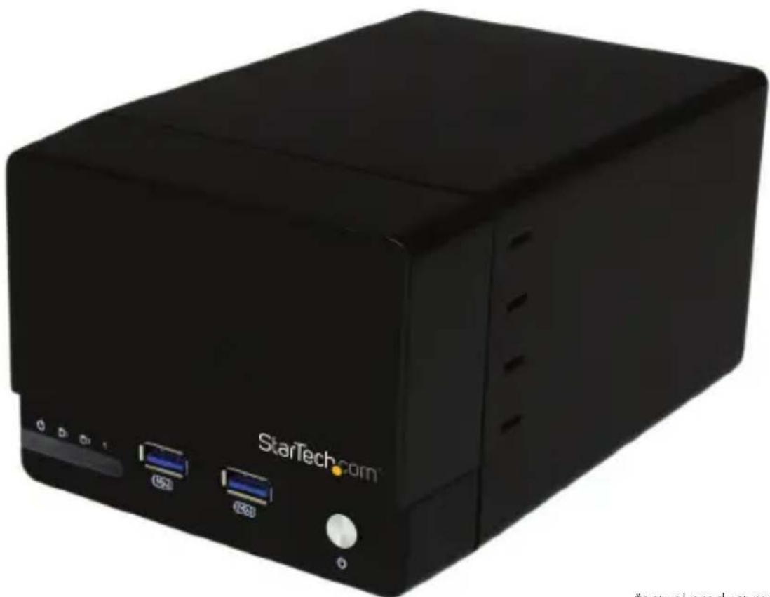
natural_image
Black StarTech.com server with two USB ports and a control knob (no visible text or symbols on the device body)*actual product may vary from photos
For the most up-to-date information, please visit: www.startech.com
FCC Compliance Statement
This equipment has been tested and found to comply with the limits for a Class B digital device, pursuant to part 15 of the FCC Rules. These limits are designed to provide reasonable protection against harmful interference in a residential installation. This equipment generates, uses and can radiate radio frequency energy and, if not installed and used in accordance with the instructions, may cause harmful interference to radio communications. However, there is no guarantee that interference will not occur in a particular installation. If this equipment does cause harmful interference to radio or television reception, which can be determined by turning the equipment off and on, the user is encouraged to try to correct the interference by one or more of the following measures:
• Reorient or relocate the receiving antenna.
- Increase the separation between the equipment and receiver.
- Connect the equipment into an outlet on a circuit different from that to which the receiver is connected.
- Consult the dealer or an experienced radio/TV technician for help.
Use of Trademarks, Registered Trademarks, and other Protected Names and Symbols
This manual may make reference to trademarks, registered trademarks, and other protected names and/or symbols of third-party companies not related in any way to StarTech.com. Where they occur these references are for illustrative purposes only and do not represent an endorsement of a product or service by StarTech.com, or an endorsement of the product(s) to which this manual applies by the third-party company in question. Regardless of any direct acknowledgement elsewhere in the body of this document, StarTech.com hereby acknowledges that all trademarks, registered trademarks, service marks, and other protected names and/or symbols contained in this manual and related documents are the property of their respective holders.
Table of Contents
Product Diagram....1
Front View .... 1
Rear View....1
Introduction......2
Packaging Contents 2
System Requirements....2
Hardware Installation....3
Technical Support 12
Warranty Information....12
Product Diagram
Front View

Rear View

1 Front Bay
2 Power LED
3 Drive Activity LEDs
4 USB 3.0 Hub + Charging Ports
5 Power Button
1 RAID Mode Switch
2 Set RAID button
3 Drive Fan
4 USB 3.0 port
5 Power adapter port
Introduction
Packaging Contents
• USB 3.0 Hard Drive Enclosure (S352BU33HR)
- USB 3.0 Cable
• Universal Power Adapter (NA/UK/EU)
- Instruction Manual
System Requirements
• 1x Computer system with available USB 3.0 (5 Gbit/s) port/USB 2.0 port (480Mbps)
- Microsoft® Windows® 2000/XP/Server 2003/Vista/Server 2008 R2/7/8 (32/64-bit), Apple® Mac® OS 9.x/10
• Linux®
- Google Chrome OS™
- 2x 3.5" SATA Hard Drives
Hardware Installation
WARNING! Hard drives and storage enclosures require careful handling, especially when being transported. If you are not careful with your hard disk, lost data may result. Always handle your hard drive and storage device with caution. Be sure that you are properly grounded by wearing an anti-static strap when handling computer components or discharge yourself of any static electricity build-up by touching a large grounded metal surface (such as the computer case) for several seconds.
- Using a Philips head screw driver (not included), remove the side mounted screw on the left front facing side of the enclosure.

- To reveal the drive bay, grasp the front panel and slide it upward.

natural_image
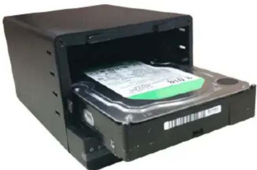
Black StarTech.com device with ports and control buttons (no readable text beyond brand name)- With the hard drive label facing upward, gently slide each of your 3.5" hard drives into the drive bays until you feel resistance.
natural_image
Black hard drive with a green card inserted into the open casing (no visible text or symbols)-
Slide the front panel back onto the S32BU33HR the same way it was removed.
-
Using a Philips head screw driver (not included), replace the side mounted screw on the left front facing side of the enclosure.
-
Using the included power adapter, connect the Power Adapter Port on the S352BU33HR to an available power outlet.
- Connect the S352BU33HR to your computer system using the included USB 3.0 cable.
- Set your desired RAID configuration and power on the device.
WARNING! In order to prepare your drives for RAID operation, this enclosure will configure newly installed drives into your desired RAID configuration. Please be aware that any data currently on the drives may be lost during this process. It is recommended that you back up all data prior to setting your RAID configuration.
a) Ensure the S352BU33HR is powered off.
b) Adjust the RAID Control Switch to your desired RAID configuration (See Available RAID Configurations).
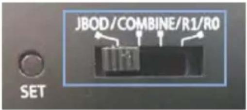
c) Press and hold the set RAID button while turning on the S352BU33HR on by pressing the Power Button.

Note: RAID configuration is only required for initial configuraiton or if you would like to change your RAID configuration.
Available RAID Configurations
The S352BU33RER enclosure supports 4 different RAID configurations. RAID is a storage technology that combines multiple hard drives into a single unit for secure data redundancy, increased volume size and/or improved performance.
Descriptions and benefits for each available RAID configuration are listed below:
JBOD - Normal
In JBOD, no RAID configuration is set and both drives appear as individual disks.
Note: For both drives to be detected while connected via eSATA the host controller must support SATA Port Multiplier.
Combine - BIG
In BIG, both drives appear together as a single large disk the size of both drives combined. This configuration enables you to create a larger volume than would be available using a single drive without the performance increase offered with RAID 0.
R1 (RAID1) - Mirroring
In RAID1 both drives appear as a single disk and data is written identically to both. This level protects your data from individual drive failure as a backup of all data is written instantly.
R0 (RAID0) – Spanning
In RAID0 both drives appear together as a larger single disk the size of both drives combined. This level can improve your performance as read and write operations are performed in parallel on separate disks.
How to Use
Accessing your Array
Once the enclosure has been attached to a computer, and powered on, your computer system will automatically recognize the drive(s) and it will be accessible as though it were installed in the system internally.
Note: If your computer fails to automatically recognize your drive it is likely your drive has not been initialized or formatted correctly. (See Drive Initialization below for further instructions.)
LED Indicators
The hard drive enclosure offers LED indicators so you can monitor drive and RAID array activity. Do not remove the enclosure from the host computer while the LEDs are flashing, as it could damage the drive or the enclosure, resulting in data loss. Please see the table below for detailed LED indication.
JBOD - Normal
| Enclosure Powered On | Drives being accessed | Drive 2 disconnected or dropped | Drive 2 reconnected | New drive connected | SI | |||
| Both Drives Installed and detected | ||||||||
| Blue | Red | RAID | ||||||
| LED | LED | LED | ||||||
| HDD1 | On Off | |||||||
| HDD2 | On Off | |||||||
| Note: N/A N/A N/A | ||||||||
R1 (RAID1) - Mirroring
| Enclosure Powered On | Drives being Accessed | Drive 2 Disconnected or Dropped | Drive 2 Reconnected New | Drive Connected Sleep | |||||||||||||||||||
| Both Drives Installed and Detected | |||||||||||||||||||||||
| Blue LED | Red LED | RAID LED | Blue LED | Red LED | RAID LED | Blue LED | Red LED | RAID LED | Blue LED | Red LED | RAID LED | Blue LED | Red LED | RAID LED | Blue LED | Red LED | RAID LED | ||||||
| HDD 1 | ON OFF | OFF | ON BLINK | OFF | ON OFF | SOLID | ON BLINK | BLINK | ON BLINK | BLINK | OFF OFF | OFF | |||||||||||
| HDD 2 | ON OFF ON BLINK OFF SOL | LID ON | BLINK ON | BLINK OFF | OFF | ||||||||||||||||||
| NOTE: | N/A | * The LEDs appear purple because of the close proximity of the Blue and Red LEDs | * The DATA is still accessible and can be updated/modified even though one of the drives are disconnected. | * No power cycle is required but recommended.* Data remains accessible but no clear indication as to if the RAID has been fully repaired.* Again LEDs look purple.* RAID LED will turn off after rebuild is complete. | * No power cycle is required but recommended.* Data remains accessible but no clear indication as to if the RAID has been fully repaired.* Again LEDs look purple.* RAID LED will turn off after rebuild is complete. | *Support HDD spin-down and LED off when suspend/U3 command*Support HDD spin-down and LED off when VBUS is gone | |||||||||||||||||
R0 (RAID0) – Spanning
| Enclosure Powered On | Drives being Accessed | Drive 2 Disconnected or Dropped | Drive 2 Reconnected New | Drive Connected Sleep | ||||||||||||||||||||
| Both Drives Installed and Detected | ||||||||||||||||||||||||
| Blue LED | Red LED | RAID LED | Blue LED | Red LED | RAID LED | Blue LED | Red LED | RAID LED | Blue LED | Red LED | RAID LED | Blue LED | Red LED | RAID LED | Blue LED | Red LED | RAID LED | |||||||
| HDD 1 | ON OFF | OFF | ON BLINK | OFF | ON OFF | SOLID | ON BLINK | SOLID | ON BLINK | SOLID | OFF OFF | OFF | ||||||||||||
| HDD 2 | ON OFF ON B | LID ON BLINK ON | OFF | |||||||||||||||||||||
| NOTE: | N/A | * The LEDs appear purple because of the close proximity of the Blue and Red LEDs | * The drive will drop from the system. | * The unit needs to be power cycled before it will pair up with the drive again.* Again LEDs look purple.* RAID LED will turn off after rebuild is complete. | N/A | *Support HDD spin-down and LED off when suspend/U3 command*Support HDD spin-down and LED off when VBUS is gone | ||||||||||||||||||
Disconnecting the Hard Drive
Windows
- Select the "Safely remove Hardware and Eject Media" icon, located in the task bar.
- Select the Mass Storage Device from the list that appears.
- Wait for the message indicating that it is now safe to remove the device.
Note: Removing the connected drive prior to receiving notification that it is safe to do so, could result in losing or corrupting data stored on the drive. Once the Safe to Remove Hardware message appears, please disconnect the enclosure from the computer by removing the USB connection.
Mac OS X
To safely disconnect the attached drive from the host computer, close any windows listing the contents of the removable drive. Once all windows are closed, click on the USB storage icon on the desktop, and drag it to the Trash Can icon on the desktop. Allow 5 seconds before physically removing the enclosure/drive from the computer.
Initializing the Hard Drive
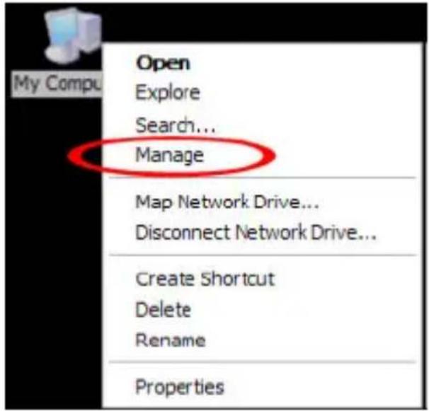
- If the drive array is new it may need to be initialized and formatted before use. From the main Windows desktop, right-click on "My Computer" ("Computer" in Vista/7/8), then select Manage. In the new Computer Management window, select Disk Management from the left window panel.

-
A dialog window should automatically appear, asking you to initialize the drive. Depending on the version of Windows, it will give you the option of either creating an "MBR" or "GPT" disk. GPT (GUID partition) is required for drives larger than 2TB but is not compatible with some older operating systems, while MBR is supported by newer and older operating systems.
-
Once initialized, locate the Disk that says it is "Unallocated" (check the listed hard drive capacity to confirm it's the correct hard drive) and then right-click in the section that says "Unallocated" and select "New Partition".

- Several on screen prompts will follow walking you through the steps to create the partition. Follow these prompts to complete partition creation.
Technical Support
StarTech.com's lifetime technical support is an integral part of our commitment to provide industry-leading solutions. If you ever need help with your product, visit www.startech.com/support and access our comprehensive selection of online tools, documentation, and downloads.
For the latest drivers/software, please visit www.startech.com/downloads
Warranty Information
This product is backed by a two year warranty.
In addition, StarTech.com warrants its products against defects in materials and workmanship for the periods noted, following the initial date of purchase. During this period, the products may be returned for repair, or replacement with equivalent products at our discretion. The warranty covers parts and labor costs only. StarTech.com does not warrant its products from defects or damages arising from misuse, abuse, alteration, or normal wear and tear.
Limitation of Liability
In no event shall the liability of StarTech.com Ltd. and StarTech.com USA LLP (or their officers, directors, employees or agents) for any damages (whether direct or indirect, special, punitive, incidental, consequential, or otherwise), loss of profits, loss of business, or any pecuniary loss, arising out of or related to the use of the product exceed the actual price paid for the product. Some states do not allow the exclusion or limitation of incidental or consequential damages. If such laws apply, the limitations or exclusions contained in this statement may not apply to you.
Hard-to-find made easy. At StarTech.com, that isn't a slogan. It's a promise.
StarTech.com is your one-stop source for every connectivity part you need. From the latest technology to legacy products — and all the parts that bridge the old and new — we can help you find the parts that connect your solutions.
We make it easy to locate the parts, and we quickly deliver them wherever they need to go. Just talk to one of our tech advisors or visit our website. You'll be connected to the products you need in no time.
Visit www.startech.com for complete information on all StarTech.com products and to access exclusive resources and time-saving tools.
StarTech.com is an ISO 9001 Registered manufacturer of connectivity and technology parts. StarTech.com was founded in 1985 and has operations in the United States, Canada, the United Kingdom and Taiwan servicing a worldwide market.


- USB 3.0 Dual 3.5" SATA HDD RAID Enclosure w/ UASP & Fast Charge USB Hub
- FCC Compliance Statement
- Use of Trademarks, Registered Trademarks, and other Protected Names and Symbols
- Table of Contents
- Product Diagram....1
- Introduction......2
- Hardware Installation....3
- Technical Support 12
- Warranty Information....12
- Product Diagram
- Front View
- Introduction
- Packaging Contents
- System Requirements
- Hardware Installation
- Available RAID Configurations
- JBOD - Normal
- Combine - BIG
- R1 (RAID1) - Mirroring
- R0 (RAID0) – Spanning
- How to Use
- Accessing your Array
- LED Indicators
- Disconnecting the Hard Drive
- Windows
- Mac OS X
- Initializing the Hard Drive
- Technical Support
- Warranty Information
- Limitation of Liability
Brand : StarTech.com
Model : S352BU33HR
Category : External hard drive enclosure