
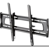
RF-TVLFMA - Wall mount Rocketfish - Free user manual and instructions
Find the device manual for free RF-TVLFMA Rocketfish in PDF.


| Product Type | TV Wall Mount |
| Brand | Rocketfish |
| Model | RF-TVLFMA |
| Compatible Screen Sizes | 42" to 90" diagonal |
| Maximum TV Weight | 125 lbs (56.6 kg) |
| Overall Dimensions (H x W x D) | 17.7 x 29.3 x 2.7 in. (450 x 743.8 x 69 mm) |
| Mount Weight | 28 lbs (12.7 kg) |
| Mount Type | Full-motion (articulating) wall mount |
| Wall Compatibility | Wood stud or solid concrete / concrete block |
| Stud Spacing | 16 to 24 inches (40 to 61 cm) |
| Tilt Adjustment | Yes, adjustable tension |
| Level Adjustment (Side-to-Side) | Yes, via level screw |
| Lateral Shift | Yes, re-positionable (not for concrete) |
| Extend / Retract | Yes, full-motion arms |
| Cable Management | Integrated channels in arms |
| Installation | DIY, instructions included |
| Included Hardware | Brackets, screws, spacers, washers, hex key, template |
| Optional Concrete Kit | CMK1 (contact customer service) |
| Warranty | Lifetime limited warranty |
| Customer Service (U.S. & Canada) | 1-800-620-2790 |
| Repair / Replace Policy | Repair with new/refurbished parts or replace at no charge |
| Safety Certification | Meets UL/ETL requirements (implied) |
Frequently Asked Questions - RF-TVLFMA Rocketfish
User questions about RF-TVLFMA Rocketfish
0 question about this device. Answer the ones you know or ask your own.
Ask a new question about this device
Download the instructions for your Wall mount in PDF format for free! Find your manual RF-TVLFMA - Rocketfish and take your electronic device back in hand. On this page are published all the documents necessary for the use of your device. RF-TVLFMA by Rocketfish.
USER MANUAL RF-TVLFMA Rocketfish
42" to 90" TV WALL MOUNT
RF-TVLFMA

natural_image
Technical line drawing of a mechanical assembly with frame elements and structural brackets (no text or symbols)
For wood-stud and concrete wall installations
Safety information and specifications......2
Tools needed....2
Package contents....3
Installation instructions ....5
INSTALLATION GUIDE
Before using your new product, please read these instructions to prevent any damage.
Safety information and specifications

IMPORTANT SAFETY INSTRUCTIONS - SAVE THESE INSTRUCTIONS
CAUTION: Do not use this product for any purpose not explicitly specified by Rocketfish.
Improper installation may cause property damage or personal injury. If you do not understand these directions, or have doubts about the safety of the
Maximum TV weight: 125 lbs. (56.6 kg)
Screen size: 42" to 90" diagonal
Overall dimensions (H × W × D):
17.7 x 29.3 x 2.7 in. (450 x 743.8 x 69 mm)
Wall mount weight: 28 lbs. (12.7 kg)
We're here for you
www.rocketfishproducts.com
For customer service, call:
1-800-620-2790 (U.S. and Canada)
installation, contact Customer Service or call a qualified contractor. Rocketfish is not responsible for damage or injury caused by incorrect installation or use.
The weight of your TV must not exceed 125 lbs. (56.6 kg). The wall must be capable of supporting five times the weight of your TV and wall mount combined.
This product contains small items that could be a choking hazard if swallowed. Keep these items away from young children!
Tools needed
You will need the following tools to assemble your new TV wall mount:
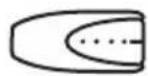
Edge-to-edge stud finder

Pencil
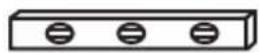
Level

natural_image
Line drawing of a drill press with labeled component (no text or symbols beyond label)Drill

Measuring tape

Socket wrench with 1/2 in. (13 mm) socket or adjustable wrench

Phillips screwdriver


Tape

Hammer

Awl
7/32 in. (5.5 mm) wood drill bit for wood stud wall
OR
3/8 in. (10 mm) masonry drill bit (concrete only)
Package contents
Make sure that you have all the hardware necessary to assemble your new TV wall mount:
1 Vertical TV bracket (Qty. 1)
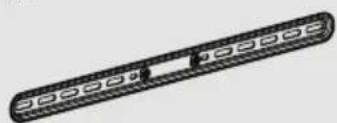
2 Horizontal TV brackets (Qty. 2)
3 Template (Qty. 1)

natural_image
Simple line drawing of a door panel with no text or symbols
natural_image
Illustration of a cylindrical mechanical component with evenly spaced holes and two circular holes (no text or symbols)
natural_image
Simple line drawing of a rectangular frame with rounded corners and evenly spaced small oval cutouts (no text or symbols)4 Arm assembly (Qty. 1)
5 Wall plate (Qty. 1)

natural_image
Technical line drawing of a mechanical assembly with no visible text or symbols
natural_image
Technical line drawing of a rectangular frame with side supports and cutouts (no text or symbols)TV Hardware
| # Hardware Qty. | |||
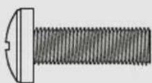
| 6 |  | M6 × 12 mm screw | 4 |
| 7 | 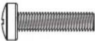 | M6 × 25 mm screw | 4 |
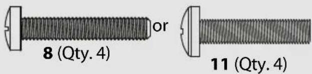
| 8 | 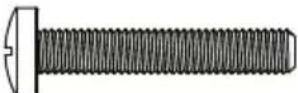 — — | M6 × 35 mm screw | 4 |
| 9 |  | M8 × 16 mm screw | 4 |
| 10 |  — — | M8 × 25 mm screw | 4 |
| 11 |  — — | M8 × 35 mm screw | 4 |
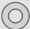
| 12 |  | M6/M8 washers | 4 |
| 13 |  | 2.5 mm spacers | 4 |
| # Hardware Qty. | |||
| 14 |  | 5 mm spacers | 4 |
| 15 |  | M5 x 10 mm TVbracket screw | 4 |
| 16 | 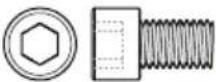 | 1/4-20 x 3/8in. Wall Platescrew | 4 |
| 17 |  | 1/4 in. washer | 4 |
| 18 |  | Locking screw | 1 |
| 19 |  | ex key | 1 |
| 20 | — |  5/16" × 3 1/2" lag screw 5/16" × 3 1/2" lag screw | 4 |
| 21 |  | 5/16 in. washer | 4 |
Concrete Installation Kit CMK1 (not included)
Contact customer service at 1-800-620-2790 to have these additional parts shipped directly to you.
| 22 | 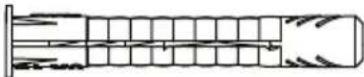 Fischer UX10 x 60RConcrete installation kit CMK1 (not included) Fischer UX10 x 60RConcrete installation kit CMK1 (not included) | 4 |
Installation instructions
Step 1 - Determine whether your TV has a flat back, irregular back, or obstructed back
1 Carefully place your TV screen face-down on a cushioned, clean surface to protect the screen from damages and scratches.
2 If your TV has a table-top stand attached, remove the stand. See the documentation that came with your TV for instructions.
3 Temporarily lay the horizontal TV brackets (2) on the back of your TV.
4 Align the screw holes in the horizontal brackets with the mounting screw holes on your TV.
5 Identify which type of back your TV may have:
- Flat back: The brackets lay flush against the back of your TV and do not block any jacks. You do not need spacers when assembling the wall mount.

- Obstructed back: The brackets block any of the jacks on the back of your TV. You will need spacers (13 or 14) when assembling the wall mount.
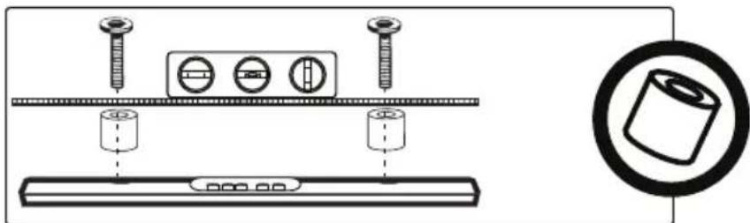
- Irregularly-shaped back: There is a gap between the brackets and some part of the back of your TV. You will need spacers (13 or 14) when assembling the wall mount.

6 Remove the horizontal brackets.
STEP 2 - Select screws, washers, and spacers
1 Select the hardware for your TV (screws, washers, and spacers). A limited number of TVs come with mounting hardware included. (If there are screws that came with the TV, they are almost always in the holes on the back of the TV.) If you don't know the correct length of the mounting screws your TV requires, test various sizes by hand threading the screws.
Select one of the following types of screws:
$$ M 6 \times 1 2 \mathrm{mm} \text { screws } (6) $$
$$ M 8 \times 1 6 \mathrm{mm} \text { screws } (9) $$
$$ M 6 \times 2 5 m m s c r e w s (7) $$
$$ M 8 \times 2 5 \mathrm{mm} \text {screws} (1 0) $$
$$ M 6 \times 3 5 \mathrm{mm} \text {screws (8)} $$
$$ M 8 \times 3 5 m m s c r e w s (1 1) $$
Use M6/M8 washers (12) for all screws.
For an irregular or obstructed TV back, also use the 2.5 mm (13) or 5 mm (14) spacers.

CAUTION: To avoid potential personal injuries and property damage, make sure that there are adequate threads to secure the brackets to your TV. If you encounter resistance, stop immediately and contact customer service. Use the shortest screw and spacer combination to accommodate your TV. Using hardware that is too long
may damage your TV. However, using a screw that is too short may cause your TV to fall from the mount.

Screw fits correctly
2 Remove the screws.
3 For a flat back TV, go to STEP 3 - Option 1: Attaching the horizontal brackets to TVs with a flat back on page 7.
-OR-
For an irregular or obstructed back, go to STEP 3 - Option 2: Attaching the horizontal brackets to TVs with irregular or obstructed backs on page 8.
STEP 3 - Option 1: Attaching the horizontal brackets to TVs with a flat back
1 Align the holes you noted on the horizontal brackets (2) with the screw holes on the back of your TV. Make sure that the brackets are level.
2 Place the washers (12) over the holes in the horizontal brackets that align with the screw holes on the back of your TV, then insert the screws (6, 7, 9, or 10) through the washers.
3 Tighten the screws until they are snug against the horizontal brackets. Do not over tighten.

You'll need

6 (Qty. 4)

7 (Qty. 4)
oror

9 (Qty. 4) 10 (Qty. 4)
or
natural_image
Pure electrical circuit lines without any symbols
Phillips screwdriver

Level
12 (Qty. 4)
2 Horizontal TV brackets (Qty. 2)
STEP 3 - Option 2: Attaching the horizontal brackets to TVs with irregular or obstructed backs
1 Place the 2.5 mm (13) or 5 mm (14) spacers over the screw holes on the back of the TV.
2 Align the horizontal brackets (2) over the spacers (13 or 14), then place the washers (12) over the holes in the horizontal brackets and insert the screws (8 or 11) through the washers, horizontal brackets, and spacers. Make sure that the brackets are level.
3 Tighten the screws until they are snug against the horizontal brackets. Do not over tighten.

You'll need


natural_image
Illustration of a cylindrical object with evenly spaced holes and a central hole, no text or symbols present.2 Horizontal TV brackets (Qty. 2)

STEP 4 - Attaching the vertical bracket
1 Place the vertical TV bracket (1) on the horizontal TV brackets (2), as shown below. Make sure that the bracket is centered and that the arrow points up.
2 Secure the vertical bracket (1) to the horizontal brackets (2) with four M5 x 10 mm TV bracket screws (15). Tighten the screws until they are snug against the horizontal brackets. Do not over tighten.

You'll need

1 Vertical TV bracket (Qty. 1)

15 (Qty. 4)

Phillips screwdriver
STEP 5 - Determine wall-mount location
NOTE:
- For more detailed information on determining where to drill your holes, visit our online height-finder at: http://mf1.bestbuy.selectionassistant.com/index.php/heightfinder
- Your TV should be high enough so your eyes are level with the middle of the screen. Normally, 40 to 60 inches from the ground.
The center of your TV will match the center of the wall plate (5). Before you drill holes in the wall:
1 Measure the distance from the bottom of your TV to the middle of the four mounting screw holes. This is measurement a.
2 Measure the distance from the floor to where you want the bottom of the TV to be placed on the wall. Keep in mind that the bottom of the TV should be placed above any furniture (such as entertainment centers or TV stands). The TV should also be above items placed on top of the furniture (like a Blu-ray player or cable box). This is measurement b.
3 Add a + b. The total measurement is the height where you want the center of the wall plate (5) to be on the wall.
4 Use a pencil to mark this spot on the wall.

You'll need

STEP 6 - Option 1: Installing on a wood stud wall
Note: Drywall covering the wall must not exceed 5/8" (16 mm).
1 Locate the stud. Verify the center of the stud with an edge-to-edge stud finder.
2 Make sure that the distance between the studs is 16 to 24 inches (40 to 61 cm).
3 Align the center of the wall plate template (3) at the height you determined in the previous step and make sure that it is level. Tape the wall plate template to the wall, then use a pencil to mark the four lag screw hole locations of the stud centers. Remove the wall plate template.
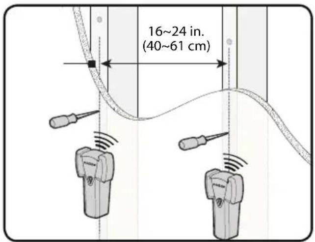

4 Drill four pilot holes to a depth of 3 1/2 in. (89 mm) using a 7/32 in. (5.5 mm) diameter drill bit.
Note: Minimum wood stud size: Common 2 x 4 in. (51 x 102 mm). Nominal 1.5 x 3.5 in. (38 x 89 mm)

5 Align the wall plate (5) with the pilot holes, insert the lag screws (20) through the washers (21) and the holes in the wall plate assembly, then tighten the lag screws only until they are firm against the wall plate assembly.


CAUTION: Avoid potential injuries or property damage! DO NOT over-tighten the lag screws (20).
You'll need

Stud finder

Level

Pencil


1/2" socket wrench

natural_image
Line drawing of a handheld electric drill (no text or symbols)Drill

natural_image
Technical line drawing of a wall plate with mounting brackets (no text or symbols)5 Wall plate

20 Lag screw (Qty. 4)

natural_image
Simple line drawing of a rectangular frame with rounded corners and no text or symbols3 Template

Tape

21 5/16 in. washer (Qty. 4)
STEP 6 - Option 2: Installing on a solid concrete or concrete block wall

CAUTION: To prevent property damage or personal injury, never drill into the mortar between the blocks. Mount wall plate directly onto the concrete surface.
Note: Minimum solid concrete thickness: 8 in (203 mm). Minimum concrete block size: 8 x 8 x 16 in. (203 x 203 x 406 mm).
1 Align the center of the wall plate template (3) at the height you determined in the previous step and make sure that it is level. Tape the wall plate template to the wall, then use a pencil to mark the four lag screw hole locations. Remove the wall plate template.
2 Drill pilot holes to a depth of 3 3/4 in. (95 mm) using a 3/8 in. (10 mm) diameter masonry drill bit.


3 Insert the concrete wall anchors (22) (refer to Concrete Installation Kit CMK1 (not included) on page 4) into the pilot holes and use a hammer to make sure that the anchors are flush with the concrete surface.

4 Align the wall plate (5) with the anchors, insert the lag screws (20) through the washers (21) and the holes in the wall plate assembly, then tighten the lag screws only until they are firm against the wall plate.

CAUTION: Avoid potential injuries or property damage!
DO NOT over-tighten the lag screws (20).

You'll need

Hammer

1/2" socket wrench

Level

Pencil

natural_image
Line drawing of a handheld electric drill (no text or symbols)Drill

3/8 in. Masonry drill bit
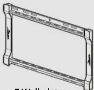
natural_image
Technical line drawing of a 5-walled plate frame (no text or symbols)5 Wall plate

natural_image
Simple line drawing of a rectangular frame with rounded corners and small rectangular cutouts on both sides (no text or symbols)3 Template
Tape

20 Lag screw (Qty. 4)

21 5/16 in.
washer (Qty. 4)

22 Concrete anchor (Qty. 4)
STEP 7 - Attach the arm assembly to the wall plate
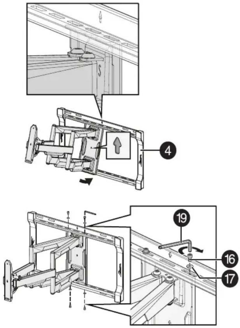
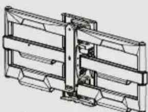
1 Hang the arm assembly (4) onto the wall plate (5) by first hooking the top support, then lowering the bottom of the arm into place.
2 Lock the arm assembly (4) to the wall plate (5) with the wall plate screws (16) and 1/4 in. washers (17), using the hex key (19).
IMPORTANT: The wall plate screws must be installed to secure the TV onto the wall plate assembly.
You'll need
natural_image
Technical line drawing of a mechanical assembly with no visible text or symbols4 Arm assembly
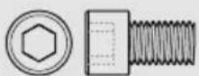
16 1/4-20 x 3/8 in.
Wall Plate screw

17 1/4 in. washer

19 3/16 in. hex key
STEP 8 - Attach the TV to the arm assembly
1 To make it easier to attach your TV to the wall plate, pull the arm assembly (4) out from the wall plate.
2 Hang the TV onto the arm assembly (4) by first hooking the top support, then lowering the bottom of the TV into place.
3 Lock the TV to the arm assembly (4) with the locking screw (18) and tighten with the Phillips screwdriver.
IMPORTANT: The locking screw (18) must be installed to secure the TV to the arm assembly.

HEAVY! You will need assistance with this step.

You'll need

Level

18 Locking screw

Phillips screwdriver
STEP 9 - Managing cables
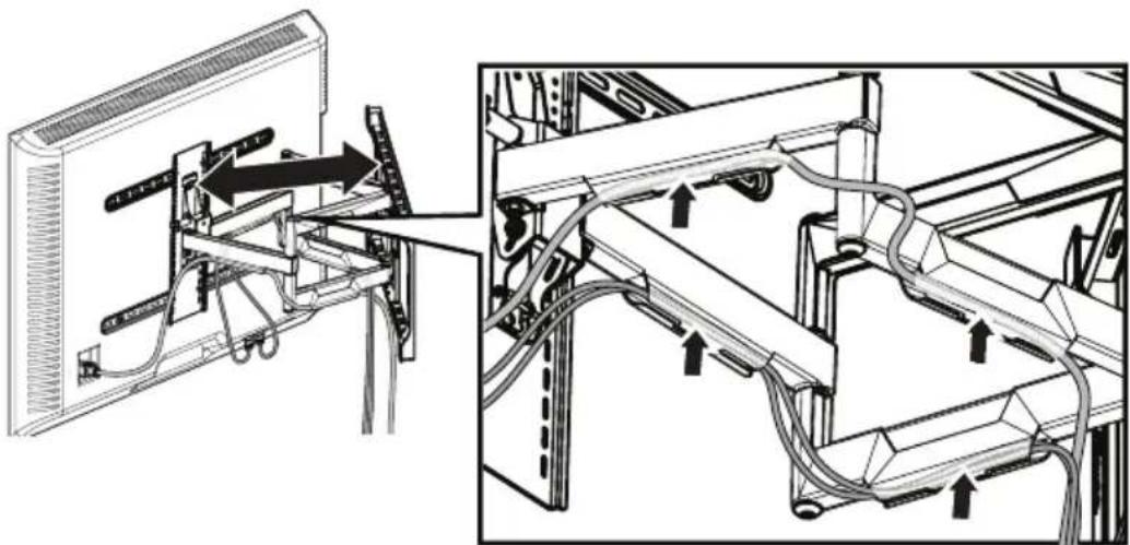
- Manage cables by fully extending the arm assembly to provide enough slack, then routing cables along the arms and inserting them into the channels on the arms, providing a clean look to your installation.
natural_image
Technical diagram showing cable routing between a monitor and server rack, with no visible text or symbols.STEP 10 - Tilt adjustment (front to back)
Your TV should adjust easily when moved, then stay in place. If your TV is too loose or too tight, adjust the side tension knob by hand or use the hex key.
NOTE: Once your TV is in place, tighten the tension knob to prevent unwanted movement. Additional tension can be applied using the 3/16 inch hex key (19).

natural_image
Technical illustration of a mechanical assembly with rotating components and internal components (no text or symbols)Step 11 - Level adjustment (side to side)
1 Loosen the locking screw (18).
2 Adjust the level of your TV by turning the level screw.
3 Re-tighten the locking screw (18) when your TV is level.

Step 12 - Lateral shift

CAUTION: Avoid potential injuries or property damage! Do NOT adjust the arm position from the center for concrete applications. The arm MUST remain centered in the wall plate for all concrete applications!
1 Disconnect cables and remove your TV (see STEP 8 - Attach the TV to the arm assembly on page 16).
2 Remove the four screws/washers and the arm from the wall plate.
3 Reposition the arm assembly on the wall plate (see STEP 7 - Attach the arm assembly to the wall plate on page 15).

natural_image
Technical diagram of a mechanical assembly with directional arrows indicating motion or assembly (no text or symbols present)4 Reattach the four screws/washers.
5 Hang your TV onto the arm assembly (see STEP 8 - Attach the TV to the arm assembly on page 16.

natural_image
Technical diagram showing a mounted monitor assembly with cable and adjustment parts (no text or symbols)Step 13 - Extend or retract
Your TV should adjust easily when moved, then stay in place. If your TV is too loose or too tight when moving, adjust the bolts using the hex key (19).
CAUTION: Avoid potential personal injury or property damage!
DO NOT remove the bolts. Only turn enough for slight adjustment.

Removing the TV from the TV mount
1 Disconnect the cables.
2 Remove the locking screw.
3 Lift the TV up and off the arm assembly.

Removing the TV from the wall mount
- To remove your TV from the wall plate assembly, disconnect all cables, then reverse the procedures in STEP 8 - Attach the TV to the arm assembly on page 16.
IMPORTANT: Your TV is heavy. You may need assistance with this step.
For customer service, call: 1-800-620-2790 (U.S. and Canada)
LIFETIME LIMITED WARRANTY
Definitions:
The Distributor* of Rocketfish branded products warrants to you, the original purchaser of this new Rocketfish-branded product ("Product"), that the Product shall be free of defects in the original manufacturer of the material or workmanship for a period of one (1) year from the date of your purchase of the Product ("Warranty Period").
For this warranty to apply, your Product must be purchased in the United States or Canada from a Best Buy branded retail store or online at www.bestbuy.com or www.bestbuy.ca and is packaged with this warranty statement.
How long does the coverage last?
The Warranty Period lasts for the useful life of the Product beginning on the date you purchased the Product. Your purchase date is printed on the receipt you received with the Product. In the event the Distributor ceases to sell the covered Rocketfish-branded product, this Limited Lifetime Warranty shall terminate for that product and there shall be no repair or replacement of the Product.
What does this warranty cover?
During the Warranty Period, if the original manufacture of the material or workmanship of the Product is determined to be defective by an authorized Rocketfish repair center or store personnel, Rocketfish will (at its sole option): (1) repair the Product with new or rebuilt parts; or (2) replace the Product at no charge with new or rebuilt comparable products or parts. Products and parts replaced under this warranty become the property of Rocketfish and are not returned to you. If service of Products or parts are required after the Warranty Period expires, you must pay all labor and parts charges. This warranty lasts as long as you own your Rocketfish Product during the Warranty Period. Warranty coverage terminates if you sell or otherwise transfer the Product.
How to obtain warranty service?
If you purchased the Product at a Best Buy retail store location or from a Best Buy online website (www.bestbuy.com or www.bestbuy.ca), please take your original receipt and the Product to any Best Buy store. Make sure that you place the Product in its original packaging or packaging that provides the same amount of protection as the original packaging.
To obtain warranty service, in the United States call 1-888-BESTBUY or in Canada call 1-866-BESTBUY. Call agents may diagnose and correct the issue over the phone.
Where is the warranty valid?
This warranty is valid only in the United States and Canada at Best Buy branded retail stores or websites to the original purchaser of the product in the county where the original purchase was made.
What does the warranty not cover?
This warranty does not cover:
- Customer instruction/education
- Installation
- Setup adjustments
• Cosmetic damage
- Damage due to weather, lightning, and other acts of God, such as power surges
- Accidental damage
- Misuse
- A b u s e
- Negligence
- Commercial purposes/use, including but not limited to use in a place of business or in communal areas of a multiple dwelling condominium or apartment complex, or otherwise used in a place of other than a private home.
- Unauthorized modification of any part of the Product, including the antenna
- Display panel damaged by static (non-moving) images applied for lengthy periods (burn-in).
- Damage due to incorrect operation or maintenance
- Connection to an incorrect voltage or power supply
- Attempted repair by any person not authorized by Rocketfish to service the Product
- Products sold "as is" or "with all faults"
- Consumables, including but not limited to batteries (i.e. AA, AAA, C etc.)
- Products where the factory applied serial number has been altered or removed
- Loss or Theft of this product or any part of the product
- Display panels containing up to three (3) pixel failures (dots that are dark or incorrectly illuminated) grouped in an area smaller than one tenth (1/10) of the display size or up to five (5) pixel failures throughout the display. (Pixel based displays may contain a limited number of pixels that may not function normally.)
- Failures or Damage caused by any contact including but not limited to liquids, gels or pastes.
REPAIR REPLACEMENT AS PROVIDED UNDER THIS WARRANTY IS YOUR EXCLUSIVE REMEDY FOR BREACH OF WARRANTY. ROCKETFISH SHALL NOT BE LIABLE FOR ANY INCIDENTAL OR CONSEQUENTIAL DAMAGES FOR THE BREACH OF ANY EXPRESS OR IMPLIED WARRANTY ON THIS PRODUCT, INCLUDING, BUT NOT LIMITED TO, LOST DATA, LOSS OF USE OF YOUR PRODUCT, LOST BUSINESS OR LOST PROFITS. ROCKETFISH PRODUCTS MAKES NO OTHER EXPRESS WARRANTIES WITH RESPECT TO
THE PRODUCT, ALL EXPRESS AND IMPLIED WARRANTIES FOR THE PRODUCT, INCLUDING BUT NOT LIMITED TO ANY IMPLIED WARRANTIES OF AND CONDITIONS OF MERCHANTABILITY AND FITNESS FOR A PARTICULAR PURPOSE, ARE LIMITED IN DURATION TO THE WARRANTY PERIOD SET FORTH ABOVE AND NO WARRANTIES, WHETHER EXPRESS OR IMPLIED, WILL APPLY AFTER THE WARRANTY PERIOD. SOME STATES, PROVINCES AND JURISDICTIONS DO NOT ALLOW LIMITATIONS ON HOW LONG AN IMPLIED WARRANTY LASTS, SO THE ABOVE LIMITATION MAY NOT APPLY TO YOU. THIS WARRANTY GIVES YOU SPECIFIC LEGAL RIGHTS, AND YOU MAY ALSO HAVE OTHER RIGHTS, WHICH VARY FROM STATE TO STATE OR PROVINCE TO PROVINCE.
Contact Rocketfish:
1-800 620-2790
www.rocketfishproducts.com
Rocketfish is a trademark of Best Buy and its affiliated companies.
* Distributed by Best Buy Purchasing, LLC
7601 Penn Ave South, Richfield, MN 55423 U.S.A.
©2024 Best Buy. All rights reserved.

Part # 6907-302062
www.rocketfishproducts.com
1-800-620-2790 (U.S. and Canada)
ROCKETFISH is a trademark of Best Buy and its affiliated companies.
Registered in some countries. Distributed by Best Buy Purchasing, LLC
7601 Penn Ave South, Richfield, MN 55423 U.S.A.
©2024 Best Buy. All rights reserved.


- 42" to 90" TV WALL MOUNT
- INSTALLATION GUIDE
- Safety information and specifications
- Tools needed
- Package contents
- TV Hardware
- Concrete Installation Kit CMK1 (not included)
- Installation instructions
- Step 1 - Determine whether your TV has a flat back, irregular back, or obstructed back
- STEP 2 - Select screws, washers, and spacers
- STEP 3 - Option 1: Attaching the horizontal brackets to TVs with a flat back
- STEP 3 - Option 2: Attaching the horizontal brackets to TVs with irregular or obstructed backs
- STEP 4 - Attaching the vertical bracket
- You'll need
- STEP 5 - Determine wall-mount location
- NOTE:
- STEP 6 - Option 1: Installing on a wood stud wall
- STEP 6 - Option 2: Installing on a solid concrete or concrete block wall
- STEP 7 - Attach the arm assembly to the wall plate
- STEP 8 - Attach the TV to the arm assembly
- STEP 9 - Managing cables
- STEP 10 - Tilt adjustment (front to back)
- Step 11 - Level adjustment (side to side)
- Step 12 - Lateral shift
- Step 13 - Extend or retract
- Removing the TV from the TV mount
- Removing the TV from the wall mount
- LIFETIME LIMITED WARRANTY
- Definitions:
- How long does the coverage last?
- What does this warranty cover?
- How to obtain warranty service?
- Where is the warranty valid?
- What does the warranty not cover?
Brand : Rocketfish
Model : RF-TVLFMA
Category : Wall mount