
39G - Unité de traitement d'air CARRIER - Free user manual and instructions
Find the device manual for free 39G CARRIER in PDF.


| Product Type | Air Handling Unit |
| Brand | Carrier |
| Model | 39G |
| Dimensions (HxWxD) | 1200 x 800 x 600 mm |
| Weight | 150 kg |
| Power Supply | 400 V, 3-phase, 50 Hz |
| Airflow Capacity | 5000 m³/h |
| Cooling Capacity | 50 kW |
| Heating Capacity | 60 kW |
| Filter Type | Bag filters, class F7 |
| Fan Type | Centrifugal, backward curved |
| Noise Level | 65 dB(A) at 5 m |
| Operating Temperature Range | -10°C to 40°C |
| Main Functions | Ventilation, heating, cooling, humidification, filtration |
| Maintenance | Clean filters every 3 months; inspect coils annually |
| Safety Features | Emergency stop, thermal overload protection, door interlocks |
| Spare Parts Availability | Filters, fans, motors, sensors, controllers |
| Repairability Index | 8/10 (modular design) |
| Certification | CE, ISO 9001 |
| Warranty | 2 years |
Frequently Asked Questions - 39G CARRIER
User questions about 39G CARRIER
0 question about this device. Answer the ones you know or ask your own.
Ask a new question about this device
Download the instructions for your Unité de traitement d'air in PDF format for free! Find your manual 39G - CARRIER and take your electronic device back in hand. On this page are published all the documents necessary for the use of your device. 39G by CARRIER.
USER MANUAL 39G CARRIER
natural_image
Exterior view of a large industrial air duct system with multiple ductwork panels and control panel (no visible text or symbols)CONTENTS
1.0 Safety Consideration 1
2.0 Pre-Installation 2
3.0 Rigging 2
4.0 Installation 3
5.0 Unit Identification 5
6.0 Section Joining Instruction 6 - 7
7.0 Fan Motor & Drives 8
8.0 Refrigerant Piping, Direct Expansion Coils 9
9.0 Guide To Starting Up 12
10.0 Guide To Servicing 13 - 16
11.0 Filter 17
12.0 Unit Dimension 18
1.0 SAFETY CONSIDERATION
Air handling units are designed to provide safe and reliable service, when operated within design specifications. To avoid injury to personnel and damage to equipment or property when operating this equipment, use good judgement and follow safe practices as outlined below.

WARNING
a) Check the assembly and component weights to be sure that the rigging equipment can handle them safely.
b) Check for adequate ventilation so that fumes will not migrate through ductwork to occupy space when welding or cutting inside air handling unit.
c) Do not remove access panel or door until fan is completely stopped.
d) Do not work on dampers until their operators are disconnected.
e) Be sure that the fan motors are properly grounded before working on them.
f) Never enter an enclosed fan cabinet or reach into the unit while the fan is running.
g) Disconnect power to the fan motor (Lock open and tag) before working on the fan.
h) Disconnect power to electric heaters (Lock open and tag) before working on or near heaters.
i) Never pressurise equipment in excess of specified test pressure.
j) Protect adjacent flammable material when welding or flame cutting. Use sheet metal or asbestos cloth to contain sparks. Have a fire extinguisher at hand and ready for immediate use.
2.0 PRE-INSTALLATION
2.1 Check items received against packing list. Notify Carrier of any discrepancies.
2.2 Examine for damage incurred during shipment. File claim with transit company if any damage is found.
2.3 Refer to rigging details as shown in (Fig.1) to transfer unit from truck to storage site.
2.4 If unit is to be stored for more than 2 weeks prior to installation, please exercise the following precautions :-
a) Choose a dry storage site that is reasonably level and sturdy to prevent undue stress and damage to the unit structure or components. Do not store on vibrating surface - damage to stationary bearing can occur.
b) Remove all fasteners and other small parts - tag and store these items in a safe place until needed.
c) Unit are shipped from the factory wrapped in protective plastic sheet. The plastic sheets may be damaged during transit or after inspection. Cover entire unit with tarpaulin or plastic coverall. Extend cover under unit if stored on ground. Secure cover with adequate tie downs.
d) When unit is stored over an extended period we recommend a monthly procedure as follows -: Remove the tarpaulin from the unit, enter fan through access door or fan section inlet, remove the belt ties (if any) and rotate fan and motor (if any) slowly by hand. This helps to re-distribute bearing grease and to prevent bearing corrosion.
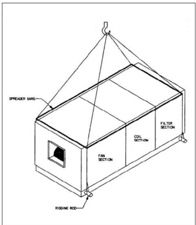
Fig. 1 Rigging Of Units
3.0 RIGGING
3.1 All 39G units are equipped with rigging hole. As such, the units can be rigged by means of the rigging rod.
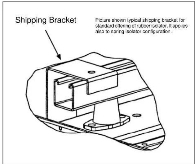
Fig. 2 Shipping Bracket

CAUTION
If a fork lift truck is used, lift only from the heavy end.
3.2 Units are shipped fully assembled or in sections, depending on size and application. The 39G Galaxy central station air handling unit are built up in "Modules" (Refer to Fig. 3). Any unit which is 22M (module) or longer in length will be shipped in shorter sections.
3.3 Do not remove skids or protective covering until unit or section is ready for final replacement.
IMPORTANT:
a) Do not lift unit by coil connections or headers.
b) Do not remove protective caps from coil piping connections until ready to connect piping.
c) Do not remove protective cover on grease from fan shaft until ready to install sheave.
d) When fan and motor drives are supplied from the factory, and unit is stored over an extended period. It's recommended that belts should be tagged and stored at a safe place until needed. This will help to minimise theft at job site.
e) Do not remove the shipping bracket (Refer to Fig. 2) that are supplied to prevent the fan housing and motor base from moving during transit. These shipping bracket should only be removed after the air handling unit is positioned and just immediately after the fan motor and drive is installed.
f) Do not remove the shipping wood block, unless the fan motor and drive is going to operate.

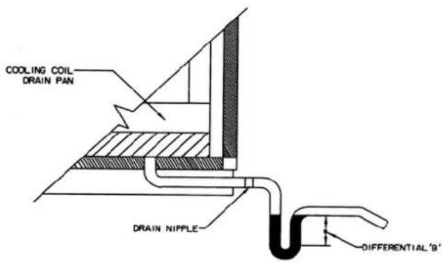
FAN OFF
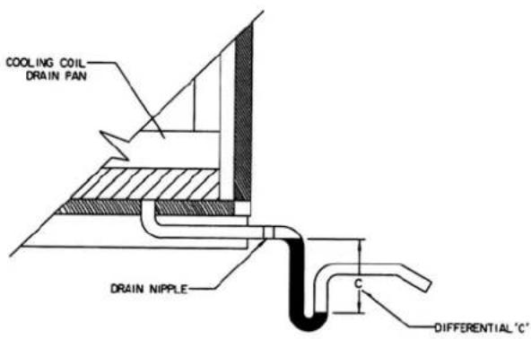
TRAP CONDITION WHEN FAN STARTS
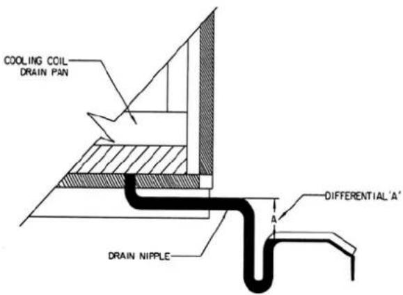
FAN RUNNING AND CONDENSATE DRAINING
Fig. 6
4.3 Typical Assemblies, Dimensions And Service Areas
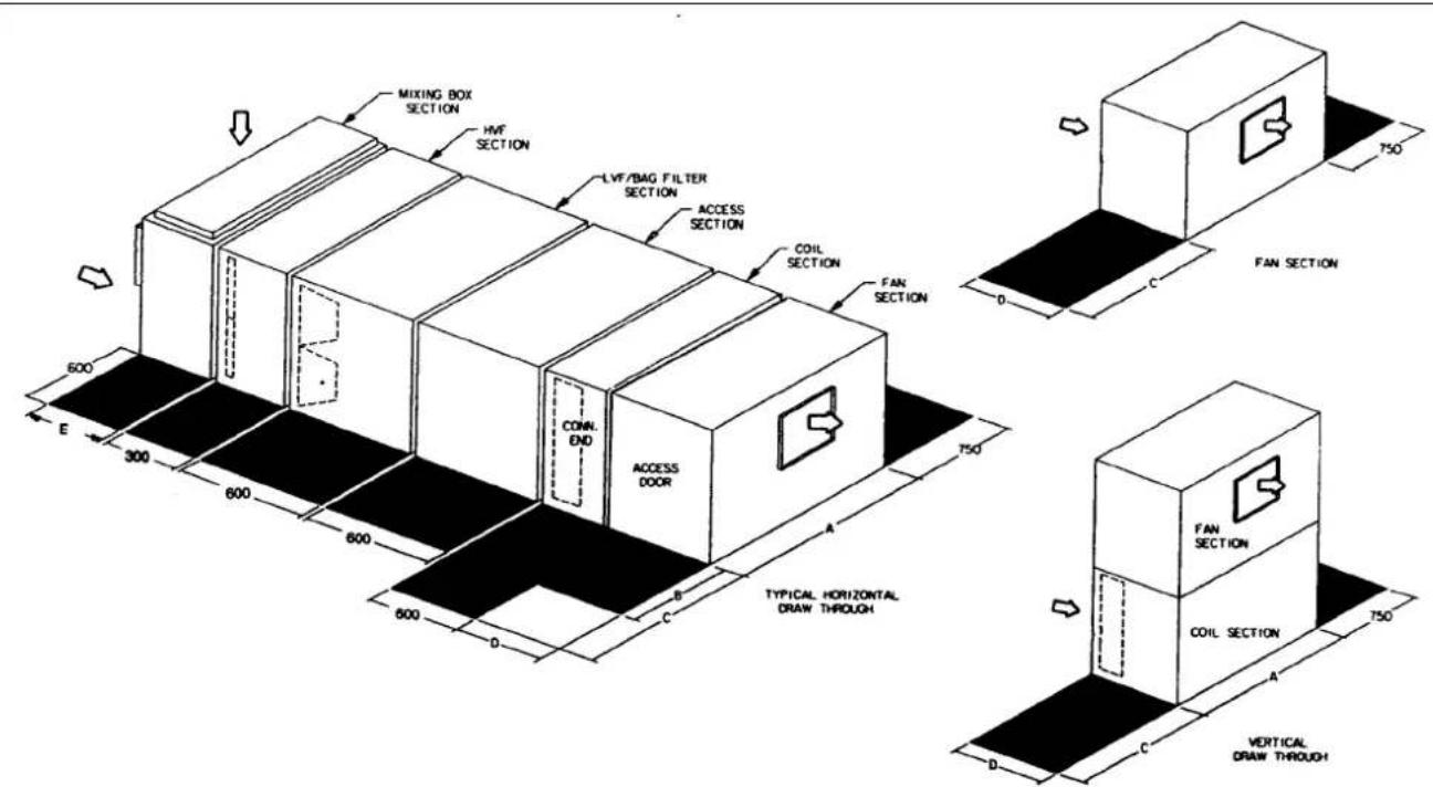

Air Flow Direction
| Unit Size | A | B C | D E Unit Size | A | B | C | D | E | ||
| 39G0608 | 800 1000 | 1100 | 600 500 | 39G1420 2000 | 1000 | 2300 1300 | 800 | |||
| 39G0609 | 900 1000 | 1200 | 700 500 | 39G1621 2100 | 1500 | 2400 1400 | 800 | |||
| 39G0711 | 1100 1000 | 1400 | 700 500 | 39G1822 2200 | 1500 | 2500 1400 | 900 | |||
| 39G0811 | 1100 1000 | 1400 | 700 500 | 39G1825 2500 | 1500 | 2800 1500 | 900 | |||
| 39G0912 | 1200 1000 | 1500 | 800 500 | 39G2025 2500 | 1500 | 2800 1500 | 900 | |||
| 39G0913 | 1300 1000 | 1600 | 800 600 | 39G2125 2500 | 1500 | 2800 1700 | 1100 | |||
| 39G0914 | 1400 1000 | 1700 | 900 600 | 39G2226 2600 | 2000 | 2900 1700 | 1100 | |||
| 39G1015 | 1500 1000 | 1800 | 900 600 | 39G2230 3000 | 2000 | 3300 1900 | 1100 | |||
| 39G1117 | 1700 1000 | 2000 | 1100 600 | 39G2234 3400 | 2000 | 3700 1900 | 1100 | |||
| 39G1317 | 1700 1000 | 2000 | 1100 600 | 39G2634 3400 | 2000 | 3700 2000 | 1100 | |||
| 39G1418 | 1800 1000 | 2100 | 1100 800 |
Note:
(1) For dimension A & D and other numeral value, add the frame thickness respectively.
\~ 50mm for 25mm casing \~ 100mm for 50mm casing
(2) Dimension C is where the access door and coil connection end applied accordingly.
Fig. 7 Typical Assemblies Dimensions and Service Area
4.4 The 39G Air Handling Units are as standard fitted with factory installed spring or rubber type anti-vibrations mounts. Externally mounted anti-vibration mounts in addition to the factory installed anti-vibration are not recommended.
4.5 When the 39G Air Handling Units are required to be suspended a platform is required. The platform must be constructed such that it is strong enough to support the whole air handling unit under operating condition. In doubt, please consult your nearest Carrier representatives.
5.0 UNIT IDENTIFICATION
Each air handling unit will have the identification sticker on the outer skin of the door to the fan section.
If identification stickers should become lost or unreadable at job site, refer to your nearest Carrier representatives for the nomenclature.
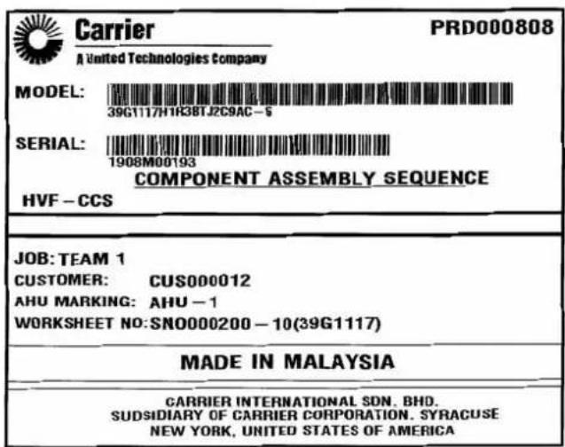
Fig. 8 Identification Sticker
6.0 SECTION JOINING INSTRUCTION
6.1 Joining between sections 25mm & 50mm (except to diffuser section)
The installation procedure for joining bracket (Pre drilled holes) are as follows:
a. Identify the correct sections which need to be joined together.
b. Make sure all proper action are taken to level the two separate sections.
c. Affix the gasket (that is supplied with the unit) along the edges of the aluminium frame that is required to be joined together. (refer figure 1)
d. Locate the pre-drilled holes along the horizontal and vertical frame.(refer figure 1)
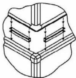
e. To install the correct quantity of joining bracket, refer to SECTION JOINING INSTRUCTION sticker. Start by placing the joining bracket between the frame and insert the bolt, nut and washer set.(refer figure 2)
f. Tighten the bolt and nut until it compress the gasket and make sure there is no leakage. The purpose of gasket is to prevent any air leakage.
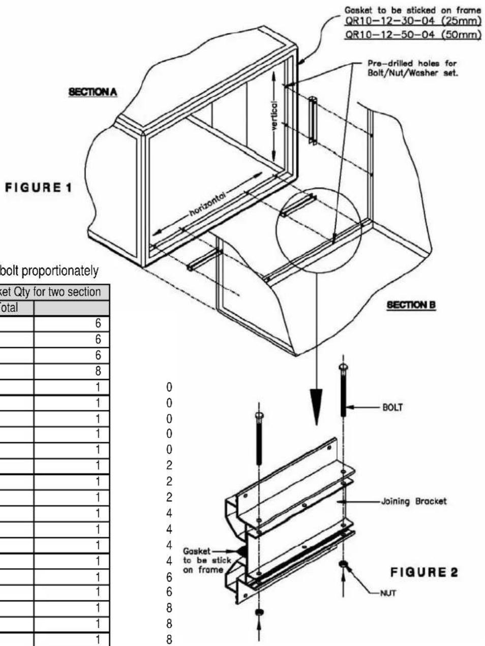
Important: Use the hole for bolt proportionately
| AHU Size | Internal Joining Bracket Qty for two section | ||
| Vertical Horizontal Total | |||
| 0608 1 | 2 | 6 | |
| 0609 1 | 2 | 6 | |
| 0711 1 | 2 | 6 | |
| 0811 2 | 2 | 8 | |
| 0912 2 | 3 | 1 | |
| 0913 2 | 3 | 1 | |
| 0914 2 | 3 | 1 | |
| 1015 2 | 3 | 1 | |
| 1117 2 | 3 | 1 | |
| 1317 3 | 3 | 1 | |
| 1418 3 | 3 | 1 | |
| 1420 3 | 3 | 1 | |
| 1621 3 | 4 | 1 | |
| 1822 3 | 4 | 1 | |
| 1825 3 | 4 | 1 | |
| 2025 3 | 4 | 1 | |
| 2125 4 | 4 | 1 | |
| 2226 4 | 4 | 1 | |
| 2230 4 | 5 | 1 | |
| 2234 4 | 5 | 1 | |
| 2634 4 | 5 | 1 | |
THIS UNIT SIZE IS ____
| ITEM25mm50mm | ||
| SCREW SET 39GA509-279 39GA509-280 | ||
| GASKET QR10-12-30-04 QR10-12-50-04 | ||
| BRACKET | 39GH539-013 | 39GH539-013A |
Fig. 9.1 Joining Bracket
6.0 SECTION JOINING INSTRUCTION
6.2 Joining to Diffuser section 25mm & 50mm
The installation procedure for joining bracket (Pre drilled holes) are as follows:
a. Identify the correct sections which need to be joined together.
b. Make sure all proper action are taken to level the two separate sections.
c. Affix the gasket (that is supplied with the unit) along the edges of the aluminium frame that is required to be joined together. (refer figure 1)
d. Locate the pre-drilled holes along the horizontal and vertical frame.(refer figure 1)
e. To install the correct quantity of joining bracket, refer to DIFFUSER SECTION JOINING INSTRUCTION sticker. Start by placing the joining bracket between the frame and insert the bolt, nut and washer set.(refer figure 2)
f. Tighten the bolt and nut until it compress the gasket and make sure there is no leakage. The purpose of gasket is to prevent any air leakage.
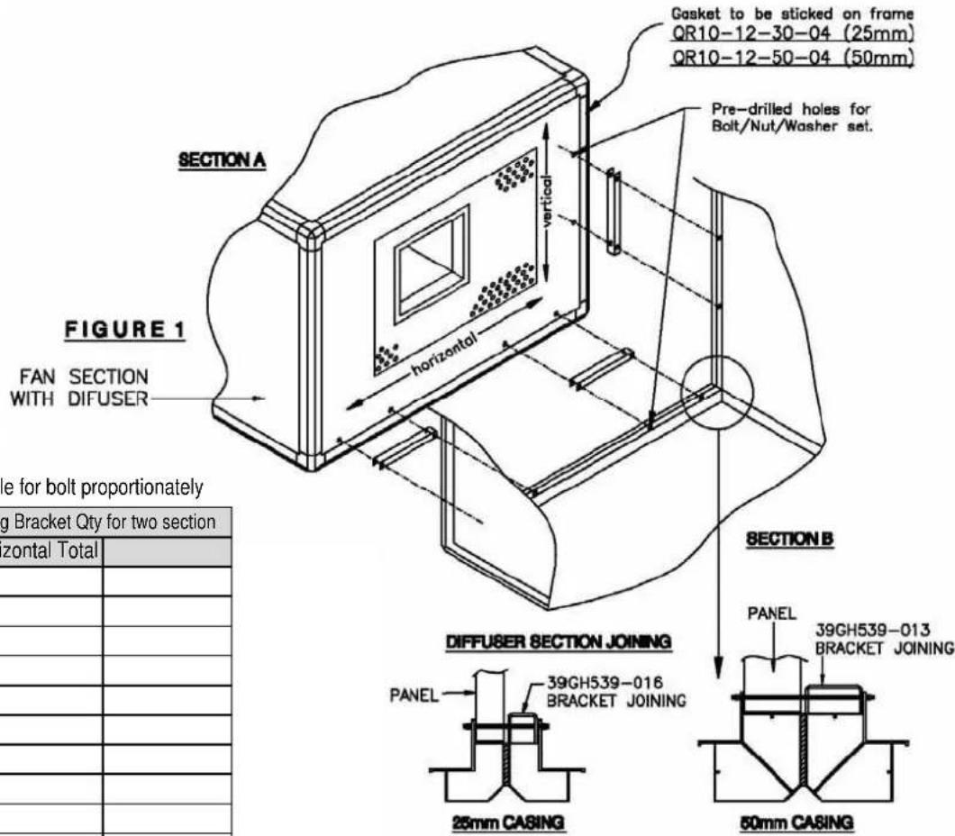
IMPORTANT use the hole for bolt proportionately
| AHU Size | Internal Joining Bracket Qty for two section | ||
| Vertical Horizontal Total | |||
| 0608 1 | 2 6 | ||
| 0609 1 | 2 6 | ||
| 0711 1 | 2 6 | ||
| 0811 2 | 2 8 | ||
| 0912 2 | 3 10 | ||
| 0913 2 | 3 10 | ||
| 0914 2 | 3 10 | ||
| 1015 2 | 3 10 | ||
| 1117 2 | 3 10 | ||
| 1317 3 | 3 12 | ||
| 1418 3 | 3 12 | ||
| 1420 3 | 3 12 | ||
| 1621 3 | 4 14 | ||
| 1822 3 | 4 14 | ||
| 1825 3 | 4 14 | ||
| 2025 3 | 4 14 | ||
| 2125 4 | 4 16 | ||
| 2226 4 | 4 16 | ||
| 2230 4 | 5 18 | ||
| 2234 4 | 5 18 | ||
| 2634 4 | 5 18 | ||
THIS UNIT SIZE IS ____
FIGURE 2
| ITEM | 25mm | 50mm |
| BRACKET JOINING | 39GH539-016 | 39GH539-013 |
| SCREW JOINING | 39GA509-279 | 39GA509-280 |
| CASKET JOINING | QR10-12-30-04 | QR10-12-50-04 |
natural_image
Pure technical line drawing of a mechanical component with no text or symbolsFig. 9.2 Joining Bracket
7.0 FAN MOTOR & DRIVES
The 39G unit will be supplied with or without the fan motor and drive from the factory. In either case, a motor base will be supplied installed on the fan and motor base channel.
7.1 Factory Installed Fan Motor & Drive
All motors and pulleys are mounted with only a "rough" alignment. The installer is responsible for the final alignment as described in the procedure.
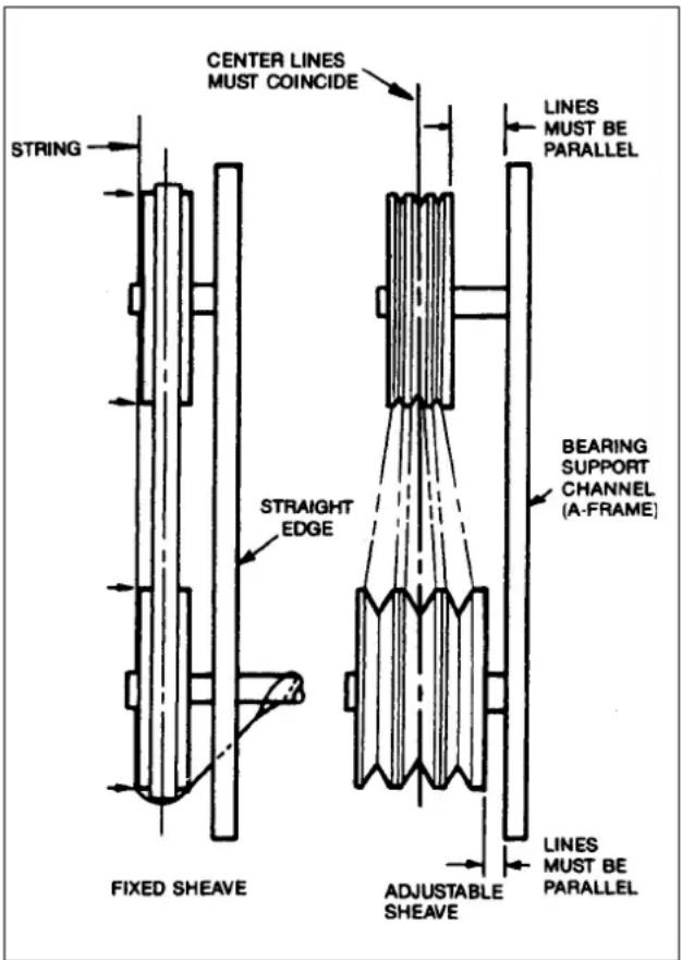
Fig. 10 Sheave Alignment
7.2 Field Supplied Fan Motor & Drive
Ensure that the motor is of the correct HP/kW frame size & electrical characteristics.
7.3 Installation of Pulleys
Install the pulley on the fan shaft and motor shaft for minimum overhang. Exercise care when mounting the pulley to the fan shaft. Excessive force may result in bearing damage. Remove rust preventing coating or grease from the shaft. Make sure that the shaft is clean and free of burrs. Lubricate the bore of the pulley before installing. Ensure that the fan and motor shafts are parallel and level. Use straight edge or a piece of string to check the
alignment of fixed pitch pulleys. If the pulleys are properly lined up, the string will touch them at the point indicated by the arrows (Refer Fig 10). For variable pitch pulleys, use a block of wood or other material to compensate for the difference in pulley width. To check the alignment of these pulleys, make sure that the centre lines of both pulleys are in line and parallel to the ("H" frame) bearing support channel. The variable pitch pulley is normally installed on the motor shaft.
7.4 Proper Belt Tension
(i) Correct tension of a V-Belt drive is carried out as follows:
(a) Fix the belts into the grooves and increase the centre distance until the belts are snug. Note: Never lever belts over sheaves.
(b) Operate the drive for a few minutes and observe the "bow" in the slack side. Tighten until only a slight "bow" appears in the slack side of the belts while they are in operation under load.
(c) During normal operation a V-Belt will seat itself in sheaves grooves and will require periodical check to maintain tension. The seating occurs more rapidly during the first 24 hours of operation, and it is very important to check drive tension carefully during this period and to retention as required.
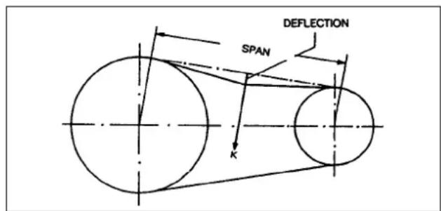
(ii) For drives where tension may be critical factor, the following procedure is recommended:
(a) Using the diagram shown below, measure the span length of the drive.
(b) At the centre of the span, apply a force K (perpendicular to the span) large enough to deflect the belt 15mm per 1 meter of span.
(c) The deflection force for any V-belt should be within the minimum and maximum force shown in the table. When the tension drops to the minimum value, readjust to the maximum value.
Deflection Force K (Newton)
| Diameter ofsmaller sheave\Cross section | Deflection force (Newton) | |||||||
| SPZ SPA SPB SPC | ||||||||
| min. | max. | min. | max. | min. | max. | |||
| 63-80 12 19 - - - - | - | |||||||
| 90-122 16 24 19 29 - - - - | ||||||||
| 125-160 19 28 26 40 | 33 50 | -- | ||||||
| 170-224 19 29 30 46 | 43 64 | 58 | 87 | |||||
| 250-355 | - | - | 32 | 48 | 51 | 77 | 79 | |
| 400-630 | - | - | - | - | 55 | 82 | 103 | |
8.0 REFRIGERANT PIPING, DIRECT EXPANSION COILS
Direct expansion coils are split into 2, 4 or 8 splits depending upon the unit size and coil circuiting. Each split requires its own distributor nozzle, expansion valve and suction piping. Suction connections are on the entering side connections for each coil split are on the air leaving side in the same order from to bottom. Refer to example on (Fig. 11).

CAUTION
Direct expansion coils are shipped pressurized with dry air. Release pressure from each coil split through valves in protective caps before removing caps. Do not leave piping open to the atmosphere unnecessarily. Water and water vapor are detrimental to the refrigerant system. Until the piping is complete, recap the system and charge with nitrogen at the end of each work-day. Clean all piping connections before soldering joints. The lower split of face split coils should be first on, last off. Row split coils utilize special intertwined circuits: either splits of these row split coils can be first on, last off.
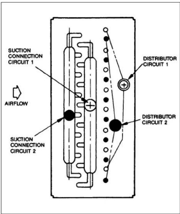
Fig. 11 Example Of Direct-Expansion Coil Distributor And Suction Connections
8.1 Suction Piping
Connect suction piping as shown in (Fig.12) for face split coil or (Fig 13) for row split coil. Suction line from coil connection to end of the 15-diameter-long riser should be same tube size as coil connection to ensure proper refrigerant velocity. Refer to Carrier System Design Manual, Part 3, and size remaining suction line header pressure drop equivalent to approximately 2.5°F. Refer to Fig 15 for piping risers to the compressor.
To minimize the possibility of flooded starts and compressor damage during prolonged shutdown, install an accumulator in the suction line or a solenoid in the liquid line of last-on, first-off split in row applications.
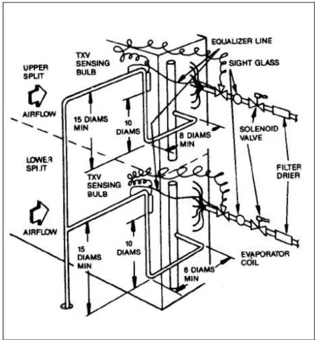
Fig. 12 Face Split Coil Suction Line Piping
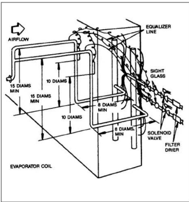
Fig. 13 Row Split Coil Suction Line Piping
8.2 Expansion Valve Piping
Distributor nozzles and thermostatic expansion valves are factory or field supplied.
Note:-
Factory supplied distributor nozzle sizes are marked on coil cover label. Be sure that correct nozzle is installed in each distributor before installing expansion valve.
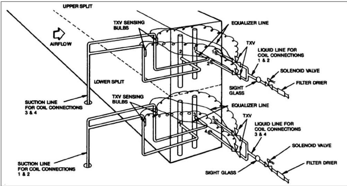
Fig. 14 Double-Circuited Face Split Coil Manifolding (Typical)
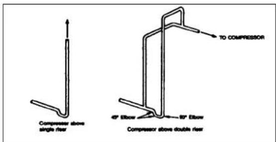
Fig. 15 Suction Line Riser Piping
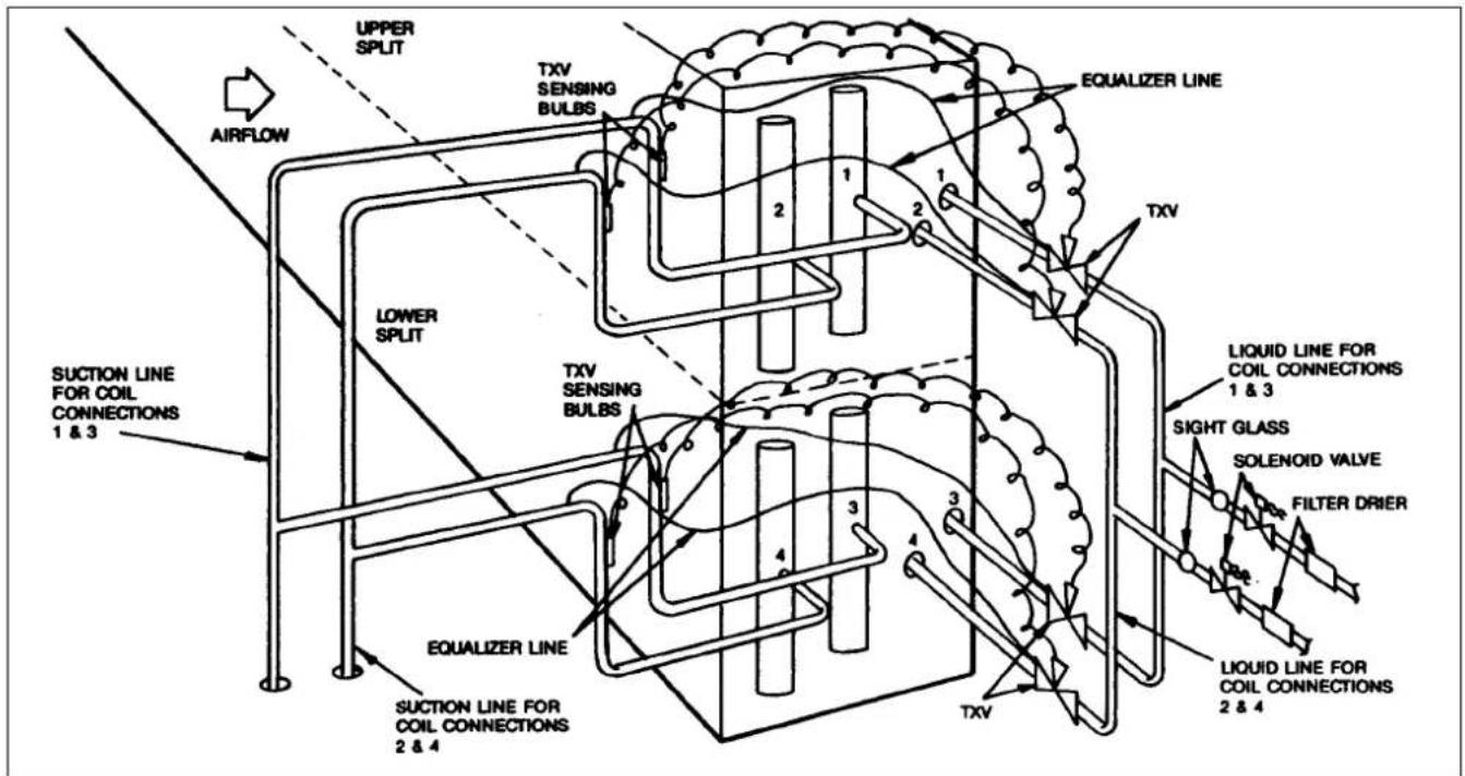
Fig. 16 Double-Circuited Row Split Coil Manifolding (Typical)
9.0 GUIDE TO STARTING UP
9.1 Ensure that all construction debris are removed from the interior of the unit.
9.2 Install filter media in all filter section. When roll filter are used, ensure that the filter media is correctly installed and that the roll filter mechanism is functioning property.
9.3 Check that the fan, motor bearing and linkages are adequately lubricated.
a) Bearings are normally shipped full of grease for corrosion protection and may run warm temporarily on start up until excess grease has been discharged.
9.4 Hand operate all linkages, such as variable inlet guide vanes and dampers to check for freedom of movement.
9.5 Check tightness of bearing set screws or locking collars.
9.6 Check tightness of set screws on blower wheel hub and pulley.
9.7 Double check the alignment and tension of the V-belts.
9.8 VERY IMPORTANT
Before energising any power to the unit, double check that all restraints that might have been used during shipping are removed from the fan shaft. The fan shaft and motor shaft must both be free-wheeling before the power is turned on. Remove all holding down bracket used to prevent the fan and motor base moving during transit.
9.9 Check the fan speed with a strobe type tachometer, or use an approximation technique with the following formula. Obtain the motor RPM from the fan motor plate. Measure the fan and motor pulley outer diameter (OD).
$$ \text { Fan RPM } = \text { Motor RPM } \times \frac {\text { Motor Pulley OD }}{\text { Fan Pulley OD }} $$
$$ e g. \text { Nameplate Motor RPM } = 1 5 0 0 $$
$$ \text { Motor Pulley OD } = 2 0 0 \mathrm{mm} $$
$$ \text { Fan Pulley OD } = 3 0 0 \mathrm{mm} $$
$$ \text { Fan RPM } = 1 5 0 0 \times \frac {2 0 0}{3 0 0} = 1 0 0 0 $$
Check that this fan RPM measured or calculated is approximately equal to the speed shown on the sticker. If the fan RPM measured or calculated, exceeds the value shown on the sticker by much, re-balancing of the fan in the field may be required.
In doubt, please refer to your nearest Carrier representatives.
9.10 Check the direction of rotation arrow label on the drive side of the fan housing indicates the correct direction of rotation. (Refer Fig 17)
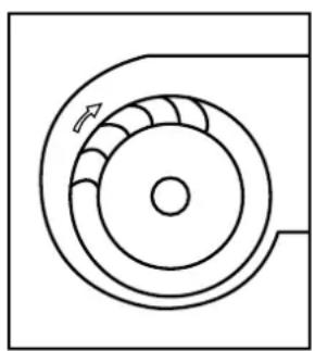
natural_image
Pure technical diagram of a circular mechanical component with no text or symbolsBackward Curved
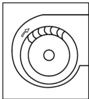
natural_image
Pure mechanical diagram showing concentric circles with a directional arrow, no text or symbols presentForward Curved
Fig. 17
9.11 Check the vibration level. If excessive vibration occurs, check the following :-
a) Variable pitch pulleys.
Normally variable pitch pulley specified to make the job of air balancing easier. Once the air balance of the system has been accomplished, replace the variable pitch pulley with the correct fixed pitch pulley for continuous application.
b) Drive misalignment.
c) Mismatched, worn or loose V-belts.
d) Blower wheel or pulley loose on the shaft.
e) Loose bearings.
f) Loose mountings.
g) Motor out of balance.
h) Pulleys (eccentric) or out of balance.
i ) Vibration isolation improperly adjusted.
j) Out of balance or corroded blower wheel (re-balance or replace as necessary).
k) Accumulation of material on blower material (remove as necessary).
I) Shipping brackets preventing the fan housing from moving during shipment. These must be removed prior to start-up.
9.12 Chilled Water and Hot Water Coil.
To vent the coils, proceed as follows :-
a) Close all coil water supply and return main valves.
b) Open all vents but no more than 2 full turns.
c) If vent is clogged up with dirt it may be necessary to remove needle valves from vents and clean as necessary.
d) Open coil water supply and return valves. Fill coil with water until all air is expelled. This occurs when the hissing sound from the vent stops and only water is oozing out from the vent.
e) Close vent needle valves.

CAUTION
The venting procedure for hot water coil must be done when the water is not heated up.
9.13 Direct Expansion Coil
Charge refrigerant in accordance with the recommendation as shown in the Installation Operating and Maintenance instructions for the condensing unit.
10.0 GUIDE TO SERVICING
10.1 Review the safety considerations at the beginning of these instructions. Good safety habits are important tools when performing servicing procedures.
10.2 Use a strobe type tachometer or calculate as per item 9.9.
10.3 To replace the fan motor, proceed as follows :-
a) Shut off the power of the motor.
b) Disconnect the tag power wires at motor terminals.
c) Loosen motor brace-to-mounting rails attaching bolts. Loosen belt tensioning bolts to adjust the motor position so V-Belts can be removed without stretching over grooves.
d) Mark belts as to position. Remove and set aside belts, tag as necessary.
e) Remove motor to motor bracket hold down bolts.
f) Remove motor pulley and set aside.
g) Remove the motor.
h) Install the new motor. Re-assemble by reversing steps a to f. Be sure to re-install multiple belts in their original position. Use a new set if required. Do not stretch belts over the pulleys. Align belts as per item 7.3.
i) Re-connect motor leads and restore power. Check fan proper rotation as described in item 9.10 Start-Up procedure.
10.4 To clean the coil, spray mild detergent solution on the coils with garden type sprayer. Rinse with fresh water. Check to ensure that the condensate line is not clogged up.
10.5 Winter shutdown for chilled water coil, proceed as follows :-
1) Anti freeze methods of coil protection.
a) Close coil water supply and return valves.
b) Drain coil as follows :
Method 1
"Break" flange of coupling at each header location, separate flange or coupling connection to facilitate coil drawing.
Method 2
It is recommended that the auxiliary drain be added to coil piping if yearly “Winterizing” of coils is anticipated. This auxiliary piping should be located at the highest and lowest point on the respective header connection for each coil. Hence, to drain the coil, open both valves to the auxiliary drain piping.
c) After coil is drained, Method 1, connect line with a service valve and union from upper nozzle to an anti freeze reservoir. Connect a self priming reversible pump between the low header connection and the reservoir. Method 2, make connection to auxiliary drain valves.
d) Fill reservoir with any inhibited anti-freeze acceptable to local authority codes.
e) Open service valve and circulate solution for 15 minutes, then check its strength.
f) If solution is too weak, add more anti-freeze until desired strength is reached, then circulate solution through coil for 15 minutes or until concentration is satisfactory.
g) Remove upper line from reservoir to reversible pump. Drain coil to reservoir and close service valve.
h) Break union and remove reservoir and it lines.
i) Leave coil flanges or coupling open and auxiliary drain valves open until spring.
10.6 Coil Removal
a) (Refer to Fig. 6 and 7) for service clearance area.
b) For chilled water coil, shut off the valves.
c) Disconnect the chilled water and condensate piping.
d) Remove coil section panel (all screws are located on the inside of the unit).
e) On header end, remove screws holding the block off and the coil casing.
f) Slide coil and baffles out of unit.
g) Lift coil using hooks at the coil casing. Do not lift by header or center of coil.
h) Reinsert coil by reversing order of procedures listed.
i) Apply sealant as necessary to edges to ensure air tightness.
10.7 Fan Shaft and Bearing
a) Disconnect power supply to fan motor.
b) Use wooden blocks to prevent the fan and motor assembly from free floating over the anti-vibration mounts.
c) Loosen motor frame adjustment to release belt tension. Remove belts.
Caution: Do not stretch belts over the pulley. Damage to belt can result.
d) Loosen bolts on bushing of pulley and remove bushing, then the pulley.
e) Loosen bearing set screw and locking collar. Drive eccentric type collar in direction opposite to shaft rotation.
f) Remove bearing while observing the following precaution. (Refer 10.8).
10.8 Blower Wheel Replacements
a) There are two type of DIDW centrifugal fans used with the 39G unit.
i) Backward Curved.
ii) Forward Curved.
b) All blower wheel and fan shaft are designed to be removed through fan housing inlet. Generally, there should be no need to disconnect the flexible connection and duct work.

CAUTION
1) Block fan wheel when removing the shaft to prevent damage to the inlet cones.
2) Use wooden blocks to prevent the fan and motor assembly from free floating over the anti-vibration mounts.
3) There may be instances where the location of the access door is not directly in line with the centre of the shaft. Here, it is necessary to remove the intermediate post, adjacent panel and door assembly. Apply sealant as necessary when these items are re-installed.
4) Exercise procedure to remove fan shaft and bearing as outlined earlier.
5) Remove bolts and nuts holding frame to the fan housing. Only the frame on the side where the blower wheel is to be removed out is required to be dismantled.
6) Removed bolts holding frame inlet cone or inlet guide vane assembly and remove accordingly.
7) Remove fan wheel and shaft as assembly.
10.9 Lubrication
Fan bearings are/not permanently lubricated. Advisable to top-up Lithium base grease every 3 months.
10.10 Filters
The 39G unit can be supplied with or without filters from the factory. There are 3 types of standard filters available.
a) High velocity panel filters (Side/Front withdrawal type).
b) Low velocity panel filters (Side/Front withdrawal type).
c) Bag filters (Side/Front withdrawal type).
d) HEPA filter EU13 particle board frame.
Notes:-
The high velocity filter frame are design to accept filter media cells with aluminium or steel frame.
* HVF & LVF Media-these filters shall be of the washable / disposable 48mm deep plated panel type, gravimetric efficiency 85% to 93% to ASHRAE 52-76.
BF Media-these bag filters shall be of the disposable dry media type, deep bed, fixed panel type, average gravimetric efficiency 85% to ASHRAE 52-76.
For other types of filters, please contact your nearest Carrier representatives.
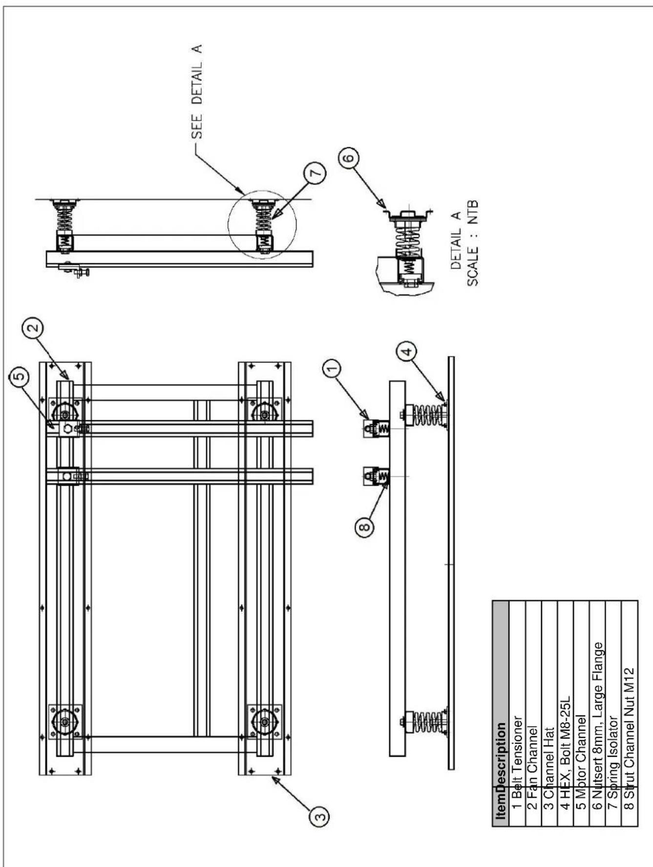
APPENDIX 1 : ASSEMBLY FAN AND MOTOR BASE
APPENDIX 2 : ASSEMBLY FAN AND MOTOR BASE
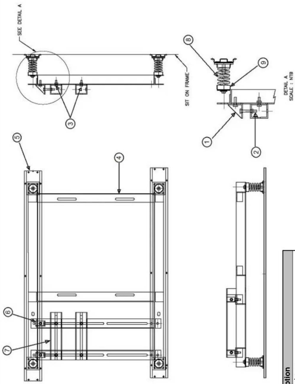
| ItemDescription |
| 1 Belt Tensioner |
| 2 Bolt, 5/8" Dia. 125mm LG Adjustment |
| 3 Bolt, 5/8" Dia. 40mm LG |
| 4 Fan Base 'L' angle 3" x 3" x 5mm thick |
| 5 Channel Hat |
| 6 Adjustment Bracket |
| 7 Motor Base 'L' angle 3" x 3" x 5mm thick |
| 8 Spring Isolator |
| 9 Assy, Cap Isolator |
FILTER TYPE, DIMENSION AND QUANTITY FOR EACH AHU SIZE
| PART NAME PART NO. | AHU SIZE | ||||||||||||||||||||||||||||||
| 06/08 | 6/09 | 07 | 1 | 08/11 | 09/12 | 09/13 | 09/14 | 10/15 | 11/17 | 13 | 17 | 14/18 | 14/20 | 16/21 | 18/22 | 18/25 | 20/25 | 21 | 25 | 22/25 | 22/30 | 22/34 | 26/34 | ||||||||
| a) HEPA Filter EU13 Particle Board Frame | |||||||||||||||||||||||||||||||
| H289 X W595 mm 3GA509-904 - 2 2 - - | 2 | 2 | 3 | 2 | 4 | 4 | 6 | ||||||||||||||||||||||||
| H391 X W495 mm 3GA509-943 - 2 - 2 2 - 8 - | |||||||||||||||||||||||||||||||
| H391 X W595 mm 3GA509-944 1 - 1 | 1 | 2 | 2 | 4 | 2 | 3 | 3 | ||||||||||||||||||||||||
| H595 X W595 mm 3GA509-902 - | 2 | 4 | 4 | 6 | 6 | 8 | 1 | 2 | 1 | 2 | 1 | 2 | 1 | 2 | |||||||||||||||||
| b) HEPA Filter EU13 Aluminium Frame | |||||||||||||||||||||||||||||||
| H289 X W595 mm 3GA509-920 - 2 2 - - | 2 | 2 | 3 | 2 | 4 | 4 | 6 | 3 | |||||||||||||||||||||||
| H391 X W495 mrr | 3GA509-951 | 2 | 2 | 2 | 8 | ||||||||||||||||||||||||||
| H391 X W595 mm 3GA509-952 1 - 1 | 1 | 2 | 2 | 4 | 2 | 3 | 3 | ||||||||||||||||||||||||
| H595 X W595 mm 3GA509-918 - | 2 | 4 | 4 | 6 | 6 | 8 | 1 | 2 | 1 | 2 | 1 | 2 | 1 | 2 | |||||||||||||||||
| c) HEPA Filter EU14 Particle Board | |||||||||||||||||||||||||||||||
| H289 X W595 mm 3GA509-925 - 2 2 - - | 2 | 2 | 3 | 2 | 4 | 4 | 6 | 3 | |||||||||||||||||||||||
| H391 X W495 mm 3GA509-953 - 2 - 2 2 - 8 - | |||||||||||||||||||||||||||||||
| H391 X W595 mm 3GA509-954 1 - 1 | 1 | 2 | 2 | 4 | 2 | 3 | 3 | ||||||||||||||||||||||||
| H595 X W595 mm 3GA509-923 - | 2 | 4 | 4 | 6 | 6 | 8 | 1 | 2 | 1 | 2 | 1 | 2 | 1 | 2 | |||||||||||||||||
| d) HEPA Filter EU14 Aluminium | |||||||||||||||||||||||||||||||
| H289 X W595 mm 3GA509-941 - 2 2 - - | 2 | 2 | 3 | 2 | 4 | 4 | 6 | 3 | |||||||||||||||||||||||
| H391 X W495 mm 3GA509-961 - 2 - 2 2 - 8 - | |||||||||||||||||||||||||||||||
| H391 X W595 mm 3GA509-962 1 - 1 | 1 | 2 | 2 | 4 | 2 | 3 | 3 | ||||||||||||||||||||||||
| H595 X W595 mm 3GA509-939 - | 2 | 4 | 4 | 6 | 6 | 8 | 1 | 2 | 1 | 2 | 1 | 2 | 1 | 2 | |||||||||||||||||
| e) 1" Bag Filter 529mm L (EU5) | |||||||||||||||||||||||||||||||
| H289 X W595 mm | 39GA509-373 | 2 | 3 | 4 | 4 | 4 | 5 | - | |||||||||||||||||||||||
| H391 X W495 mm | 39GA509-375 | 2 | 2 | ||||||||||||||||||||||||||||
| H391 X W595 mm 39GA509-376 1 - - 2 2 4 | 8 | ||||||||||||||||||||||||||||||
| H595 X W595 mm 39GA509-630 - 2 - | |||||||||||||||||||||||||||||||
| H595 X W289 mm | 39GA509-631 | 2 | 2 | 2 | 2 | 3 | 3 | 3 | 3 | ||||||||||||||||||||||
| H595 X W391 mrr | 39GA509-632 | 1 | 1 | 2 | 2 | 3 | 3 | - | - | - | - | ||||||||||||||||||||
| H595 X W595 mm | 39GA509-378 | 2 | 4 | 4 | 6 | 6 | 8 | 12 | 12 | 12 | 12 | 15 | 20 | ||||||||||||||||||
| f) 1" Bag Filter 529mm L (EU6) | |||||||||||||||||||||||||||||||
| H289 X W595 mm | 39GA509-230 | 2 | 3 | 4 | 4 | 4 | 5 | - | |||||||||||||||||||||||
| H391 X W495 mm | 39GA509-232 | 2 | 2 | ||||||||||||||||||||||||||||
| H391 X W595 mm 39GA509-233 1 - - 2 2 4 | 8 | ||||||||||||||||||||||||||||||
| H595 X W595 mm 39GA509-621 - 2 - | |||||||||||||||||||||||||||||||
| H595 X W289 mm | 39GA509-622 | 2 | 2 | 2 | 2 | 3 | 3 | 3 | 3 | ||||||||||||||||||||||
| H595 X W391 mm 39GA509-623 - - 1 1 - | 2 | 3 | |||||||||||||||||||||||||||||
| H595 X W595 mm | 39GA509-235 | 2 | 4 | 4 | 6 | 6 | 6 | 8 | 12 | 12 | 12 | 12 | 15 | 20 | |||||||||||||||||
| g) 1" Bag Filter 529mm L (EU7) | |||||||||||||||||||||||||||||||
| H289 X W595 mm | 39GA509-208 | 2 | 3 | 4 | 4 | 4 | 5 | - | |||||||||||||||||||||||
| H391 X W495 mm | 39GA509-210 | 2 | 2 | ||||||||||||||||||||||||||||
| H391 X W595 mm 39GA509-211 1 - - 2 2 4 | 8 | ||||||||||||||||||||||||||||||
| H595 X W595 mm 39GA509-618 - 2 - | |||||||||||||||||||||||||||||||
| H595 X W289 mm | 39GA509-619 | 2 | 2 | 2 | 2 | 2 | 3 | - | - | - | 3 | 3 | |||||||||||||||||||
| H595 X W391 mm 39GA509-620 - - 1 1 - | 2 | 3 | 3 | - | - | - | - | ||||||||||||||||||||||||
| H595 X W595 mm | 39GA509-213 | 2 | 4 | 4 | 6 | 6 | 6 | 8 | 12 | 12 | 12 | 12 | 12 | 15 | 20 | ||||||||||||||||
| h) 1" Bag Filter 529mm L (EU8) | |||||||||||||||||||||||||||||||
| H289 X W595 mrr | 39GA509-240 | 2 | 2 | 2 | - | - | - | - | 3 | - | 4 | - | - | 4 | 4 | 5 | - | ||||||||||||||
| H391 X W495 mm | 39GA509-242 | ||||||||||||||||||||||||||||||
| H391 X W595 mm 39GA509-243 1 - - 2 2 4 | |||||||||||||||||||||||||||||||
| H595 X W595 mm 39GA509-624 - 2 - | |||||||||||||||||||||||||||||||
| H595 X W289 mm | 39GA509-625 | 2 | 2 | - | - | - | - | - | 2 | - | - | - | 2 | - | - | - | - | - | - | 3 | 3 | ||||||||||
| H595 X W391 mm 39GA509-626 - - 1 1 - | |||||||||||||||||||||||||||||||
| H595 X W595 mm | 39GA509-245 | ||||||||||||||||||||||||||||||
| i) 1" Bag Filter 529mm L (EU9) | |||||||||||||||||||||||||||||||
| H289 X W595 mm | 39GA509-270 | 2 | 2 | - | - | - | 2 | - | - | - | - | 3 | - | 4 | - | - | 4 | 4 | 5 | - | |||||||||||
| H391 X W495 mm | 39GA509-615 | ||||||||||||||||||||||||||||||
| H391 X W595 mm 39GA509-271 1 - - 2 2 4 | |||||||||||||||||||||||||||||||
| H595 X W595 mm 39GA509-627 - 2 - | |||||||||||||||||||||||||||||||
| H595 X W289 mm | 39GA509-628 | 2 | 2 | - | - | - | - | - | - | - | - | - | 2 | - | - | - | 2 | - | - | - | - | - | 3 | 3 | |||||||
| H595 X W391 mm 39GA509-629 - - 1 1 - | |||||||||||||||||||||||||||||||
| H595 X W595 mm | 39GA509-272 | ||||||||||||||||||||||||||||||
| j) 2" HVF Filter Washable (G03) | |||||||||||||||||||||||||||||||
| H289 X W595 mm 39GA509-038 - - 2 2 - - | |||||||||||||||||||||||||||||||
| H391 X W495 mm 39GA509-040 - 2 - - 2 2 - - | |||||||||||||||||||||||||||||||
| H391 X W595 mm | 39GA509-041 1 - - 1 1 - - - 1 1 - - - 1 1 - - - 1 1 - - - 1 1 - - - 1 1 - - - 1 1 - - - 1 1 - - - 1 1 - - - 1 1 - - - 1 1 - - - 1 1 - - - 1 1 - - - 1 1 - - - 1 1 - -0.0.0.0.0.0.0.0.0.0.0.0.0.0.0.0.0.0.0.0.0.0.0.0.0.0.0.0.0.0.0.0.0.0.0.0.0.0.0.0.0.0.0.0.0.0.0.0.0.0.0,0.0.0.0.0.0.0.0.0.0.0.0.0.0.0.0.0.0.0.0.0.0.0.0.0.0.0.0.0.0.0.0.0.0.0.0.0.0.0.0.0.0.0.0.0.0.0.0.0.0 .0.0.0.0.0.0.0.0.0.0.0.0.0.0.0.0.0.0.0.0.0.0.0.0.0.0.0.0.0.0.0.0.0.0.0.0.0.0.0.0.0.0.0.0.0.0.0.0.0.0 0.0.0.0.0.0.0.0.0.0.0.0.0.0.0.0.0.0.0.0.0.0.0.0.0.0.0.0.0.0.0.0.0.0.0.0.0.0.0.0.0.0.0.0.0.0.0.0.0.0 ,0.0.0.0.0.0.0.0.0.0.0.0.0.0.0.0.0.0.0.0.0.0.0.0.0.0.0.0.0.0.0.0.0.0.0.0.0.0.0.0.0.0.0.0.0.0.0.0.0.0.,0.0.0.0.0.0.0.0.0.0.0.0.0.0.0.0.0.0.0.0.0.0.0.0.0.0.0.0.0.0.0.0.0.0.0.0.0.0.0.0.0.0.0.0.0.0.0.0.0.0..0.0.0.0.0.0.0.0.0.0.0.0.0.0.0.0.0.0.0.0.0.0.0.0.0.0.0.0.0.0.0.0.0.0.0.0.0.0.0.0.0.0.0.0.0.0.0.0.0.0,.0.0.0.0.0.0.0.0.0.0.0.0.0.0.0.0.0.0.0.0.0.0.0.0.0.0.0.0.0.0.0.0.0.0.0.0.0.0.0.0.0,.0.0.0.0.0.0.0.0.0,0.0.0.0.0.0.0.0.0.0.0.0.0.0.0.0.0.0.0,0.0.0.0.0.0.0.0.0.0.0.0,0.0.0.0.0,0.0.0.0,0.0.0,0.0,0.0,0.0,0.0,0.0,0.0,0.0,0.0,0.0,0.0,0.0,0.0,0.0,0.0,0.0,0.0,0.0,0.0,0.0,0.0,0.0,0.0,0.0,0.0,0.0,.0.0.0.0.0.0.0,0.0,0.0,0.0,0.0,0.0,0.0,0.0,0.0,0.0,0.0,0.0,0.0,0.0,0.0,0.0,0.0,0.0,0.0,0.0,0.0,0.0,0.0,0.0,0,.0.0.0.0.0.0,0.0,0.0,0.0,0.0,0.0,0.0,0.0,0.0,0.0,0.0,0.0,0.0,0.0,0,.0.0.0.0.0,0.0,0.0,0.0,0.0,0.0,0.0,0.0,0,.0.0.0.0.0,0.0,0.0,0.0,0.0,0.0,0.0,0,.0.0.0.0.0,0.0,0.0,0.0,0,.0.0.0.0,0,.0.0.0,0,.0,0,.0,0,.0,0,.0,0,.0,0,.0,0,.0,.0,.0,.0,.0,.0,.0,.0,.0,.0,.0,.0,.0,.0,.0,.0,.0,.0,.0,.0,.0,.0,.0,.0,.0,.0,.0,.0,.0,.0,.0,.0,.0,.0,.0,.0,.0,.0,.0,.0,.0,.0,.0,.0,.0,.0,.0,.0,.0,.0,0,.0.0.0.0,0,.0.0.0,0,.0.0.0,0,.0.0.0,0,.0.0.0,0,.0.0,0,.0.0,0,.0.0,0,.0.0,0,.0.0,0,.0.0,0,.0.0,0,.0.0,0,.0,0,.0,0,.0,0,.0,.0,.0,.0,.0,.0,.0,.0,.0,.0,.0,.0,.0,.0,.0,.0,.0,.0,.0,.0,.0,.0,.0,.0,.0,.0,.0,.0,.0,.0,.0,.0,.0,.0,.0,.0,.0,.0,.0,.0,.0,.0,0,.0.0.0,0,.0.0,0,.0.0,0,.0.0,0,.0.0,0,.0,0,.0,0,.0,0,.0,0,.0,0,.0,0,.0,0,.0,0,.0,0,.0,0,.0,0,.0,0,.0,0,.0,0,.0,0,.0,.0,.0,.0,.0,.0,.0,.0,.0,.0,.0,.0,.0,.0,.0,.0,.0,.0,.0,.0,.0,.0,.0,.0,.0,.0,.0,.0,.0,.0,.0,.0,.0,.0,.0,.0,0,.0.0.0,0,.0.0,0,.0.0,0,.0.0,.0,.0,.0,.0,.0,.0,.0,.0,.0,.0,.0,.0,.0,.0,.0,.0,.0,.0,.0,.0,.0,.0,.0,.0,.0,.0,.0,.0,.0,.0,.0,.0,.0,.0,.0,.0,.0,.0,.0,.0,.0,.0,.0,.0,.0,.0,.0,.0,.0,,0,.0.0.0.0,.0.0,0,.0.0,0,.0.0,0,.0.0,0,.0.0,0,.0.0,0,.0.0,0,.0.0,0,.0.0,0,.0.0,0,.0.0,0,.0.0,0,.0.0,0,.0.0,0,.0.0,0,.0,0,.0,0,.0,0,.0,0,.0,0,.0,0,.0,0,.0,0,.0,0,.0,0,.0,0,.0,0,.0,0,.0,0,.0,0,.0,0,.0,0,.0,0,.0,0,.0,0,.0, | ||||||||||||||||||||||||||||||
NOTE: Dimension in mm.
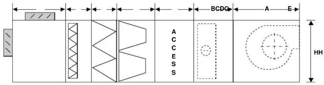
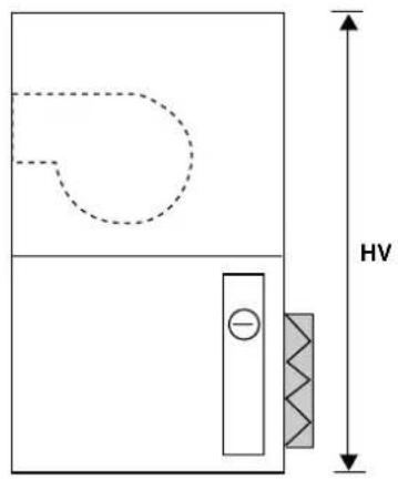
DIMENSION
| Unit size | Fan Size | Motor Range (HP) | Nominal Capacity (kW) | Nominal Airflow @ 2.5m m/s (€/s) | Section Length | FAN (Vertical Length) | FAN (Vertical Height) | Unit HH* (mm) | Unit Width (mm) | Unit HV** (mm) | ||||||
| MXB (G) | Filter | Access (C) | Coil (B) | Fan (A) | ||||||||||||
| HVF (F) | LVF (E) | BF (D) | ||||||||||||||
| 0608 | 160 1 | 1.5 | 10.2 | 552 | 500 300 | 600 600 | 600 600 | 900 | 600 | 800 | 120060 | |||||
| 180 1 | 1.5 | |||||||||||||||
| 0609 | 180 1.5 | ~ 3 600 | 14.1 | 756 | 500 300 | 600 600 | 600 600 | 900 | 600 | 600 | 900 1200 | |||||
| 200 1.5 | ~ 3 700 | |||||||||||||||
| 0711 | 200 1.5 | ~ 3 | 19.6 | 1118 | 500 300 | 600 600 | 600 600 | 700 | 900 | 700 | 700 | 1100 1400 | ||||
| 225 2 | 5 | |||||||||||||||
| 0811 | 225 2 | 5 | 24.5 | 1397 | 500 300 | 600 600 | 600 | 700600 | 900 | 800 | 800 | 1100 | 1600 | |||
| 250 2 | 5.5 | |||||||||||||||
| 0912 | 250 2 | 5.5 700 | 30.7 1711 | 500 300 | 600 600 | 600 600 | 900 | 900 | 900 | 1200 | 1800 | |||||
| 280 3 | 7.5 800 | |||||||||||||||
| 0913 | 280 3 | 7.5 | 34.5 | 1886 | 500 300 | 600 600 | 600 600 | 800 | 900 | 900 | 900 | 1300 | 1800 | |||
| 315 4 | 7.5 | |||||||||||||||
| 0914 | 315 4 | 7.5 800 | 38.3 | 2061 | 500 300 | 600 600 | 600 600 | 900 | 900 | 900 | 1400 | 1800 | ||||
| 355 4 | 10 900 | |||||||||||||||
| 1015 | 355 4 | 10 900 1900 | 49.8 | 2642 | 500 300 | 600 600 | 600 | 600 | 900 | 900 | 1000 | 1000 | 1500 | 2000 | ||
| 400 5 | 15 | |||||||||||||||
| 1117 | 400 5 | 15 900 900 | 1000 66.1 | 3429 | 500 300 | 2100 600 600 | 600 600 | 1100 | 1700 | |||||||
| 450 | 7.5 ~ 15 | 1100 | 1100 | 1100 | 2200 | |||||||||||
| 1317 | 400 5 | 15 900 900 | 1000 79.3 | 4115 | 500 300 | 2300 600 600 | 600 600 | 1300 | 1700 | |||||||
| 450 | 7.5 ~ 15 | 1100 | 1100 | 1100 | 2400 | |||||||||||
| 1418 | 450 | 7.5 ~ 15 | 90.4 4645 | 500 300 | 600 600 | 600 600 | 1100 | 1100 | 1100 | 1400 | 1800 | 2500 | ||||
| 500 | 10 ~ 20 | 1100 | 1200 | 2600 | ||||||||||||
| 1420 | 500 | 10 ~ 20 | 103.9 | 5248 | 500 300 | 600 600 | 600 600 | 1100 | 1100 | 1200 | 1400 | 2000 | 2600 | |||
| 560 | 10 ~ 20 | 1300 | 1300 | 1300 | 2700 | |||||||||||
| 1621 | 560 | 10 ~ 20 | 113.6 | 6426 | 500 300 | 600 600 | 600 600 | 1300 | 1300 | 1300 | 1600 | 2100 | 2900 | |||
| 630 | 15 ~ 25 | 1400 | 1400 | 1500 | 3100 | |||||||||||
| 1822 | 560 | 10 ~ 20 | 143.2 | 8007 | 500 300 | 600 600 | 600 600 | 1300 | 1800 | 2200 | ||||||
| 630 | 15 ~ 25 | 1400 | ||||||||||||||
| 1825 | 630 | 15 ~ 25 | 170.1 | 9246 | 500 300 | 600 600 | 600 600 | 1400 | 1800 | 2500 | ||||||
| 710 | 15 ~ 30 | 1500 | ||||||||||||||
| 2025 | 630 | 15 ~ 25 | 183.2 | 9957 | 500 300 | 600 600 | 600 600 | 1400 | 2000 | 2500 | ||||||
| 710 | 15 ~ 30 | 1500 | ||||||||||||||
| 2125 | 710 | 15 ~ 30 | 196.3 | 10668 | 500 300 | 600 600 | 600 600 | 1500 | 2100 | 2500 | ||||||
| 800 | 20 ~ 50 | 1700 | ||||||||||||||
| 2226 | 710 | 15 ~ 30 | 213.6 | 11516 | 500 300 | 600 600 | 600 600 | 1500 | 2200 | 2600 | ||||||
| 800 | 20 ~ 50 | 1700 | ||||||||||||||
| 2230 | 800 | 20 ~ 50 | 256.8 | 13484 | 500 300 | 600 600 | 600 600 | 1700 | 2200 | 3000 | ||||||
| 900 | 30 ~ 60 | 1900 | ||||||||||||||
| 2234 | 800 | 20 ~ 50 | 300.2 | 15453 | 500 300 | 600 600 | 600 600 | 1700 | 2200 | 3400 | ||||||
| 900 | 30 ~ 60 | 1900 | ||||||||||||||
| 2634 | 900 | 30 ~ 60 | 358.3 | 18444 | 50C | 300 | 600 | 600 | 60C | 60C | 1900 | 2600 | 3400 | |||
| 1000 | 40 ~ 75 | 2000 | ||||||||||||||
*HH - Height Horizontal
**HV - Height Vertical
1) External AHU Length = (Section Length + K) mm
where, K = 50mm (for 25mm casing thickness)
K = 100mm (for 50mm casing thickness)
2) External AHU Width = (Unit Width + K) mm
3) For Horizontal Unit, External AHU Height = (HH + K + 100*) mm
For Vertical Unit, External AHU Height = (HV + 2K + 100*) mm
*100mm is for unit base
4) If the External AHU Length is >1900mm, section will be split into several casing for shipping purposes.

Carrier International Sdn. Bhd. Malaysia
Carrier International Sdn. Bhd. (3385-T)
Lot 4, Jalan P/6, 43650 Bandar Baru Bangi,
Selangor, Malaysia.
Tel: 03-8925 8001
Fax: 03-8925 6589
- CONTENTS
- SAFETY CONSIDERATION
- WARNING
- PRE-INSTALLATION
- RIGGING
- CAUTION
- IMPORTANT:
- Typical Assemblies, Dimensions And Service Areas
- Note:
- UNIT IDENTIFICATION
- SECTION JOINING INSTRUCTION
- Joining between sections 25mm & 50mm (except to diffuser section)
- Joining to Diffuser section 25mm & 50mm
- FAN MOTOR & DRIVES
- Factory Installed Fan Motor & Drive
- Field Supplied Fan Motor & Drive
- Installation of Pulleys
- Proper Belt Tension
- REFRIGERANT PIPING, DIRECT EXPANSION COILS
- Suction Piping
- Expansion Valve Piping
- Note:-
- GUIDE TO STARTING UP
- VERY IMPORTANT
- Chilled Water and Hot Water Coil.
- Direct Expansion Coil
- GUIDE TO SERVICING
- Method 1
- Method 2
- Coil Removal
- Fan Shaft and Bearing
- Blower Wheel Replacements
- Lubrication
- Filters
- Notes:-
Brand : CARRIER
Model : 39G
Category : Unité de traitement d'air