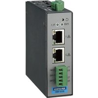
ECU-1051TL - Industrial communication gateway Advantech - Free user manual and instructions
Find the device manual for free ECU-1051TL Advantech in PDF.


User questions about ECU-1051TL Advantech
0 question about this device. Answer the ones you know or ask your own.
Ask a new question about this device
Download the instructions for your Industrial communication gateway in PDF format for free! Find your manual ECU-1051TL - Advantech and take your electronic device back in hand. On this page are published all the documents necessary for the use of your device. ECU-1051TL by Advantech.
USER MANUAL ECU-1051TL Advantech
Cloud-enabled Intelligent Communication Gateway for IIoT Applications
Before installation, please ensure that the following items have been included in your shipment:
- ECU-1051 Product
Overview
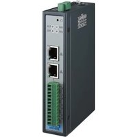
For distributed equipment management and maintenance, ECU-1051TL performs as a data publishing gateway from the field to the cloud. The operating temperature range is -40\~70°C. This module is a cost-effective solution for industrial measurement and monitoring applications.

natural_image
Exterior view of a black network switch device with ports and indicator lights (no readable text or symbols)Figure 1. Product Overview
Specifications Packing List
| Technical Specification of ECU-1051 | |
| Mounting Wall-Mount/ DIN-Rail | |
| Power Requirements | 10~30 V_DC |
| Ethernet Ports 2 x 10/100 Base-T RJ-45 ports | |
| Serial Ports 2 x RS232 / RS 485 | |
| Indicators Power, LAN(LINK, ACT), programmable | |
| Watchdog Built-in hardware & software | |
| Storage | NAND Flash/ 512MB for system image1 x Micro SD slot for data |
| Power Consumption | 2.4W @ 24 V_DC |
| Operating Temp. | -40 ~ 70 °C |
| Warranty | 2 years |
For more information on this and other Advantech products, please visit our website at
http://www.advantech.com
http://www.advantech.com/Products
For technical support and service, please visit our support website at
http://support.advantech.com.tw/support/default.aspx
This manual is for ECU-1051TL.
Part No. 2043105100
Edition 1
Printed in Taiwan
April 2020
Dimensions: (Unit: mm)

natural_image
Diagram of an electronic device showing internal components with no visible text or symbols


Figure 2. Dimension
Power Supply Wiring

Figure 3. Power Supply
| Pin Definition Description | |
| +Vs PWR V+ DC power input | |
| GND PWR V- DC power input | |
| GND |
Communication PIN Assignments
| RS-232/485 Serial Ports (Pin Assignments) | |||
| Pins 1 2 C-GND | |||
| RS-232 Rx Tx GND | |||
| RS-485 Data+ Data- GND | |||
Jumper Setting

Figure 4. Jumper Location
| Serial Ports (RS232/RS485) CN9(COM1) / CN10(COM2) | |||
| RS232 mode (3-5) (4-6) | |||
| RS485 mode, No Terminator | (1-3) (2-4) Default | ||

Installation
1. Wall Mount

natural_image
Technical line drawing of an electronic device chassis with ports and connectors, no text or symbols present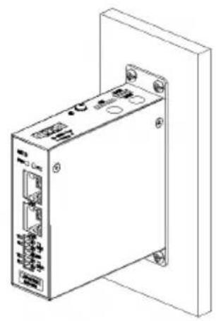
natural_image
Line drawing of a white industrial electronic device with ports and connectors, mounted on a wall (no text or symbols visible)Figure 5. Wall Mount installation
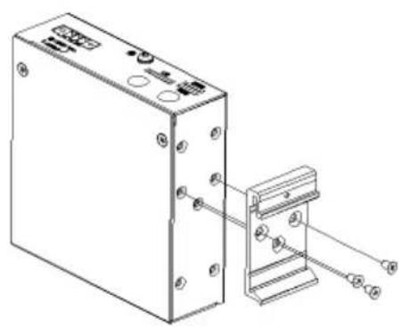
2. DIN-Rail
natural_image
Technical line drawing of an electronic device with mounting holes and a separate bracket (no text or symbols)
natural_image
Line drawing of a rectangular electronic device with ports and mounting brackets (no text or symbols)Figure 6. DIN-Rail Kit

natural_image
Pure technical line drawing of a rectangular frame with mounting holes and a handle, no text or symbols present.
natural_image
Line drawing of a wireless network device with labeled ports and connectors (no text or symbols beyond branding)Figure 7. DIN-Rail installation
4 ECU-1051TL Startup Manual
Installation (Cont.)
3. Wireless module & Antenna

Figure 8. module & antenna installation
Software and User Manual
WISE-PaaS/EdgeLink Studio is for completing ECU-1000TL and its I/O configuration and management. The OS is Windows XP/Windows 7. The software installation package as well as user's manual can be acquired from the following path: http://www.advantech.com/
Brand : Advantech
Model : ECU-1051TL
Category : Industrial communication gateway