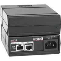
PI 115 - Injecteur de puissance PoE Extron - Free user manual and instructions
Find the device manual for free PI 115 Extron in PDF.


User questions about PI 115 Extron
0 question about this device. Answer the ones you know or ask your own.
Ask a new question about this device
Download the instructions for your Injecteur de puissance PoE in PDF format for free! Find your manual PI 115 - Extron and take your electronic device back in hand. On this page are published all the documents necessary for the use of your device. PI 115 by Extron.
USER MANUAL PI 115 Extron
PI 115 Power Injector • Installation Guide
Important Safety Instructions

This symbol, when used on the product, is intended to alert the user of important operating and maintenance (servicing) instructions in the literature provided with the equipment.

This symbol, when used on the product, is intended to alert the user of the presence of uninsulated dangerous voltage within the product enclosure that may present a risk of electric shock.
Read these instructions.
- Keep these instructions.
- Hescal earners
- False sil instructions.
• Do not use this apparent near water.
• Cleaswork with a six-earth
- Do not block any ventilation openings. Install in accordance with the max fixture instructions.
- Do not install near any heat sources such as radiators, heat regulators, so clean or other apparatused when so offered that work no hard.
- Do not defer the safety purpose of the polarized or grounding type plug. A polarized plug has two blades with one wider than the other. A grounding type plug has two blades and a third grounding proong. The wide blade or the third proong is provided for your safety. If the provided plug does not into your outlet, consult an electrician for replacement of the obsolete outlet.
- Protect the power cord from being walked on or pushed, particularly at plugs, convenience receplacles, and the point where they exit from the apparatus.
- Use only attachments and accessories specified by the manufacturer.
- During this device operation during lighting storms at which unused for long periods of time.
CAUTION:
Birk of electric shock. To-day
the risk of fire or electric shock, do not expose this apparatus to rain, moisture, dripping, splashing, or objects filled with liquids.
ATTENTION
In this case, the following
Here all servicing to quartled service personnel. Serving is required when the apparatus has been damaged in any way, such as when the power-supply core or plug is damaged. I would have been spiked or subjects have fallen into the apparatus, the apparatus has been exposed to rain or moisture, does not operate normally, or has been dropped.
ATTENTION:
- This appendix is a Class I product. This product must be connected to a small socket outlet with a protective earthing connection.
The main plug is used as the disconnect device and shell remain readily accessible.
To prevent the risk of shock, do not attempt to supervise this equipment yourself because ousting or removing covers may expose you to dangerous voltage or other hazards.
ATTENTION:
The Extron PI 115 Power Injector supplies power to one Extron PoE compatible product. This guide provides instructions for an experienced installer to install and connect the PI 115.
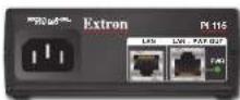
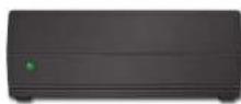
Rear Panel Front Panel
Installation
Step 1 - Mounting
ATTENTION:
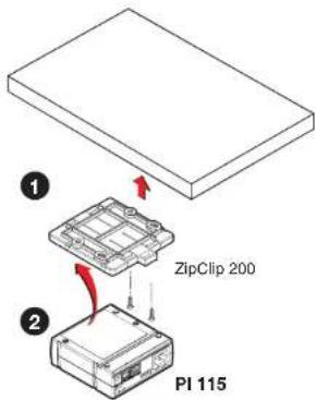
To attach the power injector to the ZipClip 200 mounting clip:
- Insert the bottom of the power injector down into the clip, starting with one end.
- Pivot the other end down and press until the clip snaps into place.
To remove the power injector from the ZipClip:
- Press the tab (①) on the ZipClip.
- Pivot the power injector and lift it out of the ZipClip (2).
To fasten the tie wraps for cable strain relief:
- Attach the power injector to the ZipClip 200 mounting clip as described previously.
- Fasten the power output cords to the ZipClip base.
a. Insert tie wraps along the notches on the side of the power injector and through the tie wrap anchor points on the ZipClip, then around the cord.
b. Connect and pull the tie wraps until they are secure. Do not over tighten.


Mounting to Rack Rails Using a ZipClip
- Fasten the ZipClip 200 mounting clip to a rack rail using two rack screws as shown in the diagram on the right (①).
- Insert the power injector into the ZipClip as described previously and press to snap it into place (②).

Mounting to a Rack Shelf
These power supplies are one-quarter rack wide. Up to four power supplies can be mounted side by side directly onto a rack shelf.
- Align the threaded holes in the bottom of the power injector with the holes in an Extron rack shelf. Fasten the supply to the shelf with two
4-40 x 3/16 inch screws
(1) as shown on the right.

- Bolt the rack shelf to the rack ( ②).
Rack Mounted
000000000
Furniture Mounting
- Attach the ZipClip to the furniture using two or more wood screws (included) as shown at right (①). Make sure the clip is oriented with the appropriate side facing the mounting surface and with the tab accessible from the front of the furniture.
- Insert the power injector into the ZipClip as described previously and press to snap it into place (2).
Step 2 — Cabling
For the best performance, see Twisted Pair Recommendations on page 2.
- Connect a network switch or an Extron twisted pair transmitter product to the LAN port (A) of the power injector using a straight-through cable. The device plugged into this connector needs to be powered by a local power source.
- Connect an Extron PoE compatible product that requires remote power to the LAN+PWR OUT port (B) using a straight-through cable.
- Connect AC power to the PI 115 ( C ).
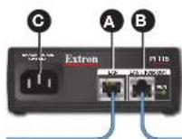
← To network or XTP device
To Extron PoE compatible device that can be powered via PoE
NOTE: Do not use two power injectors on the same cable run to remotely power the transmitter and receiver. The diagram below shows this type of application, which is not recommended by Extron.
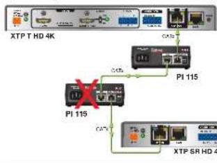
flowchart
graph TD
    A["XTP T HD 4K"] --> B["Port 1"]
    A --> C["Port 2"]
    A --> D["Port 3"]
    A --> E["Port 4"]
    B --> F["PI 115"]
    C --> G["PI 115"]
    D --> H["PI 115"]
    E --> I["PI 115"]
    F --> J["Port 5"]
    G --> K["Port 5"]
    H --> L["Port 5"]
    I --> M["Port 5"]
    J --> N["XTP SR HD 4K"]
    K --> N
    L --> N
    M --> N
NOT RECOMMENDED
LED Indicators
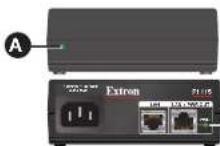
A Front panel power LED indicator — Lights to indicate the PI 115 is receiving power.
B Rear panel PWR LED Indicator — Indicates various power states of the connected endpoints (see the table below).
| LED State | Port Status |
| Unlit | The endpoint is not connected or cannot be powered. |
| Lit | The endpoint is receiving power from the PI 115. |
| Blinking | There is a power overload fault, or power allocation is exceeded. |
Twisted Pair Recommendations
Supported Cables
The PI 115 is compatible with CAT 5e, 6, 6a, and 7 shielded twisted pair (F/UTP, SF/UTP, and S/FTP) and unshielded twisted pair (U/UTP) cable.
ATTENTION:
Cable Recommendations
Extron recommends using the following practices to achieve full transmission distances up to 330 feet (100 meters) and reduce transmission errors.
Use Extron XTP DTP 24 SF/UTP cable for the best performance.
- XTP DTP 24/1000 Non-Plenum 1000 feet (305 m) spool 22-236-03
• XTP DTP 24P/1000 Plenum 1000 feet (305 m) spool 22-235-03 - XTP DTP 24 Plug Package of 10 101-005-02
• If you are not using XTP DTP 24 cable, at a minimum, Extron recommends 24 AWG, solid conductor, STP cable with a minimum bandwidth of 400 MHz.
• Terminate cables with shielded connectors to the TIA/EIA T568B standard.
- Limit the use of more than two pass-through points, which may include patch points, punch down connectors, couplers, and power injectors. If these pass-through points are required, use CAT 6 or 6a shielded couplers and punch down connectors.
Number of Patches Maximum Transmission Distance
| 1 or 2 | 330 feet (100 meters) |
| 3 | 280 feet (85 meters) |
| NOTE: Using more than three patches with the PI 115 yields varying maximum cable lengths. Limit the use of RJ-45 patches in the system. |
NOTE: When using CAT 5e or CAT 6 cable in bundles or conduits:
• Do not exceed 40% fill capacity in conduits.
- Do not comb the cable for the first 20 meters where cables are straightened, aligned, and secured in tight bundles.
- Loosely place cables and limit the use of tie wraps or Velcro".
- Separate twisted pair cables from AC power cables.
| TIA/EIA T568B |
| Pin Wire Color |
| 1 White-orange |
| 2 Orange |
| 3 White-green |
| 4 Blue |
| 5 White-blue |
| 6 Green |
| 7 White-brown |
| 8 Brown |
| Pins: 123458/8 |
| Insert Twisted Pair Wires RJ-45 Connector |
Application Diagrams
PI 115 Remote Power to the Transmitter

flowchart
graph TD
    A["Extron XTP T HD 4K XTP Transmitter"] --> B["Extron PI 115 XTP Power Injector"]
    B --> C["Extron XTP SR HD 4K XTP Receiver"]
    D["Single CATx cable is spread of: Digital Video, Digital Audio, Bithroccional IR Control, Bithroccional RS-232 Control, Ethernet, Remote Power"] --> E["12V Local Power Supply"]
    E --> F["ATx"]
PI 115 Remote Power to the Receiver
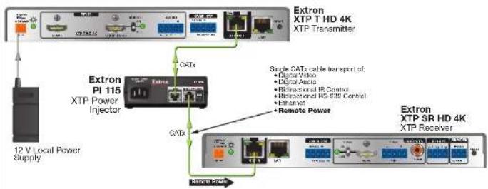
flowchart
graph TD
    A["Extron PI 115 XTP Power Injector"] --> B["CATs"]
    B --> C["Extron XTP T HD 4K XTP Transmitter"]
    B --> D["Extron XTP SR HD 4K XTP Receiver"]
    E["12 V Local Power Supply"] --> A
    F["Single CATs cable transport of: Digital Audio, Digital Audio, Bilinear IR Control, Bilinear HD-322 Control, Ethernet, Remote Power"] --> B
    G["Remote Power"] --> D
Safety Instructions • English
This symbol, when used on the product, is intended to alert the user of important operating and maintenance (servicing) instructions in the literature provided with the equipment.
This symbol, when used on the product, is intended to alert the user of the presence of uninsulated dangerous voltage within the product enclosure that may present a risk of electric shock.
Cautions and General Guidelines
Head instructions • Tisec and circetals of instructions before using the equipment.
Retain instructions • The safety instructions should be kept for future reference.
Follow warnings • Follow all warnings and instructions opened on the equipment or in the laser information.
Avoid attachments + Do not use tools or attachments that are not recommended by the equipment manufacturer because they may be hazardous.
Avoid water • Do not use this or other electrical equipment near water. Given the device with a dry cloth only.
Warnings
Power and electrical safety
CAUTION: Electrical shock that may result in injury. To reduce the risk of fire or electric shock, do not expose this approach to rain, moisture, dripping, splashing, or objects filled with liquids.
Power sources • This equipment should be operated only from the power source indicated on the product. This equipment is intended to be used with a main power system with a ground diet (practical conductor. The third (grounding) pin is a safety feature, or not else up to bypass or disable it.
ATTENTION: This apparatus is a Class I product. This product must be connected to a main socket outlet with a protective earthing connection.
Power disconnection = To remove power from the equipment solely remove all power cords from the rear of the equipment, or the desktop power module (it detachable) or from the power source receptacle (wall plug)
Power plug as a disconnection device. The main plug is used as the disconnect device and shell retain readily openable. In other words, it the power plug must be accessible and easy to ripling from the power source.
When to unplug the unit • Unplug this device during lightning storms or when it will be unused for long periods. Unplug the device before sending.
Power cord protection • Power cords should be routed so that they are not likely to be stepped on or pinched by items placed upon or against them. Protest the cord particularly at plugs, convenience receptacles, and the points where they exit the devices.
Polarized and grounding plugs • Do not detect the safety purpose of the polarized or grounding type plug. A polarized plug has two blades with one wider than the other. A grounding type plug has two blades and a third grounding progr. The wide blade or the third arang are provided for your safety. If the provided plug does not fit into your outlet, consult an electrician to replace the absolute outlet with a safer one.
Servicing + Refer all servicing to qualified service personnel. Servicing is required when the apparatus has been damaged in any way, such as when the power-supply cord or plug is damaged, liquid has soon spilled into an objects have taken into the device, or when the devices has been exposed to rain or rainwater, does not operate normally, or has been cropped. To prevent the risk of shock, do not attempt to serve this equipment yourself best as opening or removing covers may expose you to dangerous voltage or other hazards.
Ventilation, mounting, and temperature
Ventilation slots and openings • If the equipment has slots or holes in the procedure, these are pravided to prevent overheating or sensitive components inside. Do not block any ventilation opening, as this may cause the product to malfunction. Install the device in accordance with the manufacturer's instructions.
Temperature - Do not install piezette devices near any heat source such as radiators, heat registers, stoves, or other apparatus (including amplifier) that produce heat.
PI 115 Remote Power to TLP Pro, MLC Plus, or IPL Pro Device

flowchart
graph TD
    A["Extron PI 115"] --> B["TLP Pro 1025T"]
    C["Extron PI 115"] --> D["MLC Plus 100"]
    E["Extron PY 115"] --> F["IPC P Pro S 1.xl"]
    G["Network"] --> A
    H["Network"] --> C
    I["NOTE: Before using the PI 115, check the user guide for your Extron product to see if the device can be powered through a midspan power injector."] --> A
    J["Network"] --> C
| Extron USA: Headquarters1,900,633,9878 (trade USA/Canada Only) | Extron Europe(60,3687,8472 (trade Europe Only)-81,33,463,4046-81,33,453,7056 FAX | Extron India1900,3070,3777 (trade India Only)+81,80,8055,3717+81,80,8055,8737 FAX | |
| Extron USA - West: Extron USA - East | |||
| +1,714,431,1950+1,916,850,1233+1,714,431,1977 FAX - 1,916,850,1001 FAX | Extron Japan-81,3,351,1,7655-81,3,351,1,7656 FAX | Extron China+85,21,3780,1588+85,21,3780,1688 FAX | |
| Extron Asia+85,333,400 FAX+85,333,400 FAX | Extron Middle East+8714,299,1800+8714,299,1880 +FX | Extron Korea+82,2,3444,1571+82,2,3444,1675 FAX | 68-3699-01 Rev. B01 22 |
- PI 115 Power Injector • Installation Guide
- Important Safety Instructions
- CAUTION:
- ATTENTION
- ATTENTION:
- Installation
- Step 1 - Mounting
- Mounting to Rack Rails Using a ZipClip
- Mounting to a Rack Shelf
- Furniture Mounting
- Step 2 — Cabling
- LED Indicators
- Twisted Pair Recommendations
- Supported Cables
- Cable Recommendations
- Application Diagrams
- Safety Instructions • English
- Cautions and General Guidelines
- Warnings
- Power and electrical safety
- Ventilation, mounting, and temperature
Brand : Extron
Model : PI 115
Category : Injecteur de puissance PoE