
CPSPV6000ETLA - Solar panel CyberPower - Free user manual and instructions
Find the device manual for free CPSPV6000ETLA CyberPower in PDF.


| Product Type | Monocrystalline Solar Panel |
| Model | CPSPV6000ETLA |
| Brand | CyberPower |
| Rated Power | 400 W |
| Open Circuit Voltage (Voc) | 49.5 V |
| Maximum Power Voltage (Vmp) | 41.0 V |
| Short Circuit Current (Isc) | 10.4 A |
| Maximum Power Current (Imp) | 9.8 A |
| Dimensions (L x W x H) | 1722 x 1134 x 30 mm |
| Weight | 22 kg |
| Cell Type | Monocrystalline Silicon |
| Number of Cells | 120 |
| Efficiency | 20.5% |
| Frame Material | Anodized Aluminum |
| Front Cover | Low Iron Tempered Glass |
| Connector Type | MC4 Compatible |
| Operating Temperature Range | -40°C to +85°C |
| Maximum System Voltage | 1500 V DC |
| Certifications | IEC 61215, IEC 61730, UL 1703 |
| Warranty | 25 Years Linear Power Output |
| Installation Method | Roof or Ground Mount |
| Maintenance | Periodic cleaning with water and mild detergent; inspect for damage |
| Safety Features | Overcurrent Protection, Anti-corrosion coating, Secured mounting points |
Frequently Asked Questions - CPSPV6000ETLA CyberPower
User questions about CPSPV6000ETLA CyberPower
0 question about this device. Answer the ones you know or ask your own.
Ask a new question about this device
Download the instructions for your Solar panel in PDF format for free! Find your manual CPSPV6000ETLA - CyberPower and take your electronic device back in hand. On this page are published all the documents necessary for the use of your device. CPSPV6000ETLA by CyberPower.
USER MANUAL CPSPV6000ETLA CyberPower
Single Phase Grid-tied PV Inverter
Installation & User's Manual
CPSPV3000ETLA
CPSPV3600ETLA
CPSPV6000ETLA

Ver. 1.1
Contents
1 Safety....1
1.1 Intended to Use....1
1.2 Symbols on Equipment 1
1.3 Safety Information....2
2 Introduction....3
2.1 Applicability....3
2.2 Scope of Delivery....3
2.3 Equipment Description....4
3 Installation 5
3.1 Installation Area 5
3.2 PV Array Consideration 5
3.3 Mounting the PV Inverter....6
3.4 DC Wiring 8
3.5 AC Wiring 8
3.6 Communication Wiring 9
4 Start-up....10
4.1 Display, LED and Buttons....10
4.2 First Start-up....10
5 Operation....12
5.1 Display Flowchart....12
6 Troubleshooting....14
7 Decommissioning 16
8 Technical Data....17
1 Safety
1.1 Intended to Use
This product is a Grid-tied PV inverter for PV systems that converts direct current (DC) from PV array into grid alternating current (AC). It is suitable for indoor and outdoor use.
The DC input ports must only be connected to PV strings instead of battery or other kinds of DC sources.
1.2 Symbols on Equipment
The following warnings and symbols are used on the equipment (inverter)
| Symbol | Description |
 | Risk of electric shockThe inverter operates at high voltage. All work on the product must be performed by qualified persons only. |
 | Risk of electric shock after isolationAfter disconnecting the inverter from all power sources, wait the indicated time before doing work on the equipment. If not avoided, can result in injury or death. |
 | WarningInstall the equipment according to the instruction, or may result in injury or equipment damaged. |
 | Hot surfaceThe inverter surfaces can get very hot. Toughing the surface can result in injury due to heat. |
 | No isolation transformerThe inverter is not isolated between DC input and AC output. |
 | Read the instructionsIt is mandatory to read and observe the manual and instructions. |
 | Grounding conductorIndicates the position for the grounding conductor terminal. |
1.3 Safety Information
In order to prevent personal injury or property damage and to ensure long-term operation with the inverter, please observed all safety information in this section.
| Symbol | Description |
 | Risk of electric shockIndicates dangerous electrical conditions, can cause injury and/or death if not avoided. |
 | WarningIndicates a hazardous non-electrical conditions, can cause injury, death and/or damage to the property or equipment if not avoided. |
 | NoticeIndicates a hazardous non-electrical conditions, can cause damage to the equipment if not avoided. |
 | InformationIndicates important information to ensure the system work normally Not safety-relevant. |

WARNING! High voltage from PV strings
When PV modules are exposed to sunlight, dangerous high DC voltage is present in the DC connectors.
- Do not touch the DC conductors, include the uninsulated cable ends.
- Do not disconnect the DC connectors from the equipment under load. An electric arc may occur and lead to electric shock and burns.
- Before doing any work on the inverter, disconnect the inverter from all power sources and wait for 5 minutes at least.

WARNING! High voltage due to ground fault
If ground fault occurs, uninsulated components may present high voltage. Touching the live parts may cause electric shocks.
- Before touch the inverter metal parts, always disconnect the equipment from all power sources.

WARNING! Hot surface
The surfaces of the equipment may get very hot while operating and need tens minutes to
cool down after shutdown.
- Do not touch the hot surface.
- Wait half hour for the surfaces to cool down before doing work on the equipment.
- Observe the requirements of mounting.

WARNING! Heavy equipment
The inverter is heavy, can cause injury if drops to somebody
- When mounting the equipment, 2 persons to life and mount it.
- Securely mount the equipment on a solid wall.
- Observe the instructions of installation.

NOTICE! Damage to the equipment due to non-sealed connector
If moisture or dust goes into the inverter, may cause damage to the unit.
- Remember to seal the communication port after wiring
- Check all PV inputs and Grid connection are well-sealed
2 Introduction
2.1 Applicability
The manual is applicable to these products
- CPSPV3000ETLA
- CPSPV3600ETLA
- CPSPV6000ETLA
2.2 Scope of Delivery
Check the goods of delivery for completeness and any visible damage. Contact your distributor if any good of delivery is incomplete or damaged. Refer to Fig. 2-1 for unpacking the package.

| Item | Quantity | Designation |
| A | 1 | PV Inverter |
| B | 1 | AC plug |
| C | 1 | Wall-mounting plate |
| D | 1 | Manual |
Fig. 2-1 Unpacking and contents
2.3 Equipment Description
This device is a single phase Grid-tied transformerless PV inverter, converts the direct current (DC) from PV strings into a single phase alternating current (AC). The AC is fed into the utility grid.

Fig. 2-2 Inverter overview
| Position | Function |
| 1 | LCD display |
| 2 | Buttons |
| 3 | LED indicators |
| 4 | Rating label |
| 5 | DC switch |
| 6 | DC connectors |
| 7 | RS-485 Communication |
| 8 | Vent |
| 9 | AC connector |
| 10 | Auxiliary grounding terminal |
3 Installation
3.1 Installation Area

WARNING! Do not install the inverter:
- Near to a heat source. High temperature decreases the output power and service life of the inverter
- In a dusty place
- Exposed directly to sunlight
- Near flammable materials or gases
- In a place that can be touched inadvertently
You can install the inverter indoor and outdoor when the requirements are met.
Installation clearance
Inverter needs enough space to dissipate the heat, please observe the clearance requirements below.
3.2 PV Array Consideration
PV modules require,
- Not grounded to the PV+ or PV- terminals
- Have IEC61730 class A rating
- PV cables are protection class II certified (double insulated)

RNING! Check Voc of the PV strings
- Make sure the PV input voltage is always less than the max. input voltage rating of inverter at any conditions (Must consider the lowest ambient temperature condition)
PV string MPP voltage should be within the MPP voltage range of the inverter. It is
recommended that PV capacity is within 0.8-1.2 rated output power.
3.3 Mounting the PV Inverter
Unpack the delivery
- Before opening the package, check the label to make sure that the delivery is correct.
- Take out the accessories and buffer packaging materials.
- Move the inverter to the installation area (shall be performed by 2 persons).
- Check the model name on rating label on product to make sure that it is the correct unit.
- Read the instructions

Fig. 3-1 Inverter installation requirements
Mounting procedure

WARNING! Mounting surface must be solid
Make sure that the mounting surface (wall, metal support, etc.) can hold the weight of the inverter
-
Make sure the clearance around the inverter after wall-mounted meet the requirements.
-
If necessary, make holes on to the mounting surface and install anchors.
- Use the appropriate screws to fasten the wall-mounting plate to the mounting surface.
- Move the inverter so that it is slightly above and that it touches the wall-mounting plate.
- Lower the inverter on to the wall-mounting plate.
- Install and tighten M4 nuts with washers to secure the kit and inverter.

Fig. 3-2 The inverter dimensions
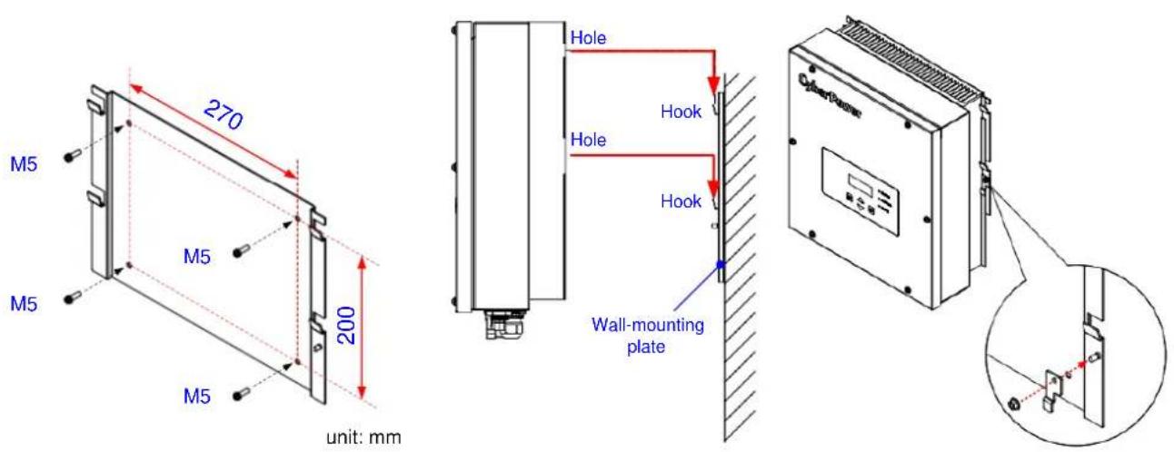
Fig. 3-3 Mounting the inverter
3.4 DC Wiring

WARNING! Check the polarities of PV strings
- Before connecting the PV strings, make sure that the polarities are correct.
-
Isolate the inverter from all power sources.
-
Set the DC switch on the inverter to OFF position.
-
Make sure all the PV strings are compatible with the inverter, and Voc is always less than the max. input voltage rating at any conditions (consider the lowest ambient temperature condition).
-
Connect the corresponding connectors of strings to the PV inputs of the inverter (make sure the +/- polarities are correctly connections). You can hear a click if connected well.

Fig. 3-4 DC wiring
3.5 AC Wiring

WARNING! Must install suitable circuit breaker for the inverter
- Installer must install a circuit breaker between inverter AC output and Grid mains.
Recommend AC breaker,
| Model | Tripping type and rating |
| CPSPV6000ETLA | Type B/C, 30A |
| CPSPV3600ETLA | Type B/C, 30A |
| CPSPV3000ETLA | Type B/C, 20-30A |
Wiring procedure,
Please be noticed, the maximum accept wire conductor size is 6.0 mm2 (10AWG), 10AWG is recommended for 30A circuit breaker.
- Isolate the inverter from all power sources.
- Remove around 20mm of the outer jacket from the AC cable.
- Remove 8-10mm of the insulation jacket of each conductor.
- Put the AC cable through the gland and shell of AC plug.
- Install and tighten the conductors in the correct L, N and PE terminals on the insert of AC plug.
- Install the insert into the shell correctly, you would hear a click if connected well.
- Tighten the gland to seal the AC cable and AC plug.
- Connect the AC plug to the receptacle on the inverter, you would hear a click if connected well.
- If necessary, connect an additional PE connector with a cable lug to the auxiliary grounding terminal.

Fig. 3-5 AC wiring
3.6 Communication Wiring

INFORMATION! Use twisted pair wires for RS-485
For reliable communication, please use twisted pair wires for the RS-485 communication
Unshielded twisted pair (UTP) cable is recommended to use for RS-485 D+/D- communication.
Procedure:
- Loosen the 4 screws and remove the cover.
-
Loosen and remove the gland nut and rubber.
-
Remove 20mm of the outer jacket of cable.
-
Remove 10mm of the insulation jacket of one twisted pair conductors (ex. Orange/white and orange).
-
Install the wires in the appropriate terminals (D+ and D-).
-
If there're multi inverters, have to connect IN and OUT terminal in JR2 except the end one, refer to Fig. 3-4 for the RS-485 communication wiring. Switch on the terminal resistor (SR1) in the end one, but keep SR1 OFF in the other units.
-
Place back the cover and tighten it.
-
Put back the rubber and tighten the gland to seal the cable.

flowchart
graph TD
    A["Data logger"] --> B["Switch OFF SR1"]
    B --> C["Switch ON SR1"]
    C --> D["Output"]
    style A fill:#f9f,stroke:#333
    style B fill:#ccf,stroke:#333
    style C fill:#cfc,stroke:#333
    style D fill:#fcc,stroke:#333
Fig. 3-4 RS-485 communication wiring
4 Start-up
4.1 Display, LED and Buttons
The inverter can automatically operate when both PV input and AC output are powered on and settings are correct. At first start up, installer must set some necessary parameters, then, inverter can start to operate. It would automatically shut down at the nighttime and back to operate during daytime.
4.2 First Start-up
Procedure:
-
Make sure the PV strings have enough voltage (>200Vdc) and power
-
Make sure the Grid power is switch OFF
-
Turn on the DC switch on the inverter
-
Wait for few seconds and the display will show some information as below, setup the
settings. Fig. 4-1 shows the display, LED indicators and buttons positions. Fig. 4-2 shows the 1st start up setting procedure, please key in the correct settings according to local grid code.


Fig. 4-1 Buttons, display and LEDs positions

flowchart
graph TD
    A["Set Date & Time: ▶2017-05-05 (Y/M/D)<br>09:33 (24H format)<br>Confirm"] --> B["Set Language ▶English<br>Français"]
    B --> C["Set Grid Code: ▶VDE0126<br>VPC<br>VDE0126-1-1"]
    C --> D["ENT twice Done"]
    A -->|→| E["ENTESC"]
    B -->|→| F["ENTESC"]
    C -->|→| G["ENTESC"]
    D -->|→| H["ENTESC"]
Fig. 4-2 Settings for 1st start-up
- If there are multi inverters connect RS-485, must setup the ID for each inverter, Display Configuration → General Settings → RS485ID.
- Display shows "No Grid" alarm since AC output is switched off, turn on the AC breaker.
- Inverter will be doing some self-tests and countdown to connect to grid when passed self-tests and the Grid condition are within the operating ranges.
5 Operation
When both AC and PV are power on and within the operating range, inverter would connect to the Grid automatically. User can check the basic operation by display, LED and/or RS-485 communication. For better DC switch life, if user wants to shut down the inverter, please switch off AC first, then, switch off DC switch.
5.1 Display Flowchart
Fig. 5-1 is home page. Display goes back to this page when user didn't press any button for 3 minutes. In this page, press any button can enter menu page, menu has "Meter", "Energy Log", "Event Log", "Device Info." and "Configuration".
Status Output power
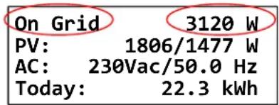
Fig. 5-1 Home page
In Configuration page, you can set
- Date, time, language, RS-485 ID and LCD contrast in General Settings page
- Grid-relevant settings in Grid Settings page (Need password). Consist of Code and Detailed pages. You can adjust the voltage and frequency protection values in "Detailed" page.

flowchart
graph TD
    A["►Meter\nEnergy Log\nEvent Log\nDevice Info."] --> B["Meter"]
    B --> C["Energy Log"]
    C --> D["Today: 22.3 kWh\n6.2 Hrs\nTotal: 1730 kWh\n432 Hrs"]
    C --> E["Event Log"]
    E --> F["Max. 30 events recorded"]
    E --> G["Device Info."]
    G --> H["CPSPV5000ETLA\nS/N: VNBXXXXXXXXX\nInstall: 2016-02-10\nDSP/Red: 1.10/1.10"]
    G --> I["Configuration"]
    I --> J["►General Settings\nGrid Settings\nInput Settings\nReturn to Default"]
    I --> K["►Return to Factory"]
    I --> L["General Settings"]
    L --> M["►Date: 2019-05-04\nTime: 14:36\nLanguage EN\nRS485ID 002"]
    L --> N["►LCD Contrast 04"]
    I --> O["Grid Settings"]
    O --> P["►Code VDE0126/TW Detailed"]
    I --> Q["Input Settings"]
    Q --> R["►Separate Parallel"]
    A --> S["►Configuration"]
Fig. 5-2 Display pages
6 Troubleshooting
If any error, warning or fault is occurring, homepage will display the occurring event on the left-top corner (Fig. 5-1). You can refer the following table to do simple troubleshooting.
Error
| Code | Error | Cause | What to do |
| E00 | No Grid | AC breaker is o or lose ulity power | Check the AC breaker is on.Check AC voltage and frequency are normal. |
| E01 | AC Freq High | AC frequency has over the seng | Check Grid condion. If okay, check the inverter Grid protecon sengs are meet the Grid condion. |
| E02 | AC Freq Low | AC frequency has under the seng | |
| E03 | AC Volt Hi | AC voltage has over the seng | |
| E04 | AC Volt Low | AC voltage has under the seng |
Warning
| Code | Warning | Cause | What to do |
| W00 | PV1 Volt Low | PV1 has under the operang range | It is normal when sunrise, sunset and rainy day. Call service same fault occurs again in sunny day. |
| W01 | PV2 Volt Low | PV1 has under the operang range | |
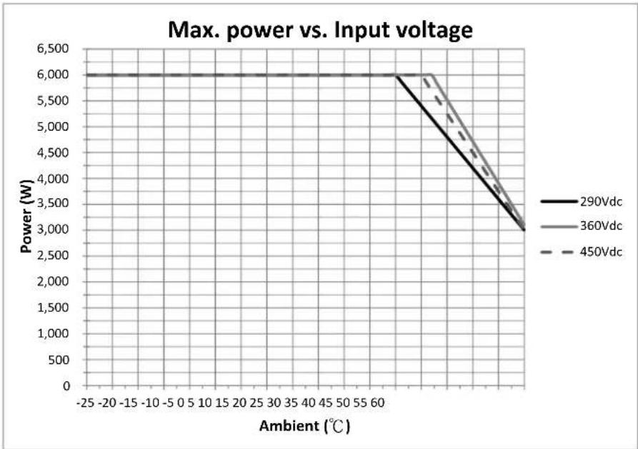
| W08 | PW De-rang | Inverter can't output rated power due to temperature or else | Refer to the de-rang curves and check the inverter condion. |
Fault
| Code | Fault | Cause | What to do |
| F01 | AC Idc | AC output current has high DC component | Shut down the inverter and re-start. Call service if same fau has occurred several mes within a short me. |
| F05 | Temp Low | Low ambient temperature | The inverter would back to operate if ambient temperature back to operang range. |
| F06 | Temp High | High ambient temperature | The inverter would back to operate if cool down. |
| F07 | Tsensor | Temperature sensor is failed | Call service. |
| F14 | FW Not Match | Firmware is not compatible to each other | Upgrade rmware to the last or compatible version. |
| F15 | DSP ADC 1 | A/D reading is abnormal | Call service. |
| F16 | DSP ADC 2 | A/D reading is abnormal | Call service. |
| F17 | DSP ADC 3 | A/D reading is abnormal | Call service. |
| F18 | DSP ADC 4 | A/D reading is abnormal | Call service. |
| F19 | Red ADC 1 | A/D reading is abnormal | Call service. |
| F20 | Eciency | Eciency is abnormal | Call service. |
| F22 | HW COM1 | Communicaton between DSP and Red. Is failed | Call service. |
| F24 | GND Curr. | Residual current has over limit | Shut down the inverter and re-start. Call service if same fau has occurred several mes within a short me. |
| F25 | HW RCMU | RCMU circuit is failed | Call service. |
| F26 | Insulaon | The equivalent resistance is under limit | May occur during rainy days. Call service if same fault occurs in sunny day. |
| F28 | Rly Short | When driver is o, the relay is sll short | Call service. |
| F29 | Rly Open | When driver is on, the relay is sll open | Call service. |
| F31 | BUS OVR | BUS has over voltage range | Check the PV voltage <550Vdc. Shut down and re-start the inverter, call service if same fault occurs again. |
| F42 | HW CT Fail | Current sensor is failed | Call service. |
| F45 | AC HW OCP | AC output has over hardware current limit | Shut down and re-start the inverter, call service if same fau occurs again. |
| F46 | Aux PWR Fail | Auxiliary power is failed | Call service. |
| F48 | Manual OFF | The inverter has received OFF command | Check the max. power seng and ON/OFF seng. |
| F60 | PV OCR | PV input1 or 2 has triggered over current protecon | Shut down and re-start the inverter, call service if same fau occurs again. |
7 Decommissioning
Procedure
- Turn off the AC breaker that connected to the inverter.
- Turn off the DC switch on the inverter.
- Disconnect all AC, PV strings and communication connectors.
- Remove the locking nuts between the inverter and the wall-mounting plate.
- Lift and remove the inverter from the wall-mounting plate.

WARNING! High voltage inside
Do not open the inverter. Even all power sources are disconnected from the inverter, dangerous voltage may still be present inside.
8 Technical Data
Specification
| Model CPSPV3000ETLA CPSPV3600ETLA CPSPV6000ETLA | |||
| PV Input | |||
| MPP voltage range (Vdc) 290-500 340-500 | 290-500 | ||
| Maximum input power (Watts) 3900 4680 7 | 800 | ||
| Maximum input voltage (Vdc) | 550 | ||
| Operating voltage range (Vdc) | 150-550 | ||
| Startup voltage (Vdc) | >200 | ||
| Number of MPPT 1 1 2 | |||
| Maximum MPPT current (Adc) 11 11 11 / 1 | 1 | ||
| Maximum short current (Adc) | 14 14 14 / 14 | ||
| Max. backfeed current (A) | 0 | ||
| Grid-Tied Output | |||
| Nominal voltage (Vac) | 1PH, 220 / 230 | ||
| Nominal frequency (Hz) | 50 / 60 | ||
| Maximum output power (W/VA) | 3000 / 3300 | 3600 / 4000 | 6000 / 6100* |
| Maximum output current (Aac) | 14.5 | 17.3 | 27.3 |
| Power factor | ≈1.0 (-0.9 to +0.9 adjustable) | ||
| Max. inrush current (Aac) | 42A peak, 0.15ms | ||
| Max. fault current (Aac) | 99A peak, 0.04ms | 106A peak, 0.04ms | 130A peak, 0.04ms |
| Max. over current protection (Aac) | 22 25 30 | ||
| Management & Communications | |||
| LCD panel | 20*4 Text LCD display | ||
| LED indicator | Green/Orange/Red | ||
| Button | ESC/UP/DOWN/ENTER | ||
| Communication port | RS-485 | ||
| General | |||
| Type | Non-isolated | ||
| Operating temperature (°C) | -25 to +60 | ||
| Humidity range (%) | 0-100 (non-condensing) | ||
| Max. Altitude (m) | 3000 | ||
| Efficiency, peak/EU (%/%) | 97.7 / 97.3 | 97.7 / 97.4 | 97.7 / 97.3 |
| Weight (kg) | 14.5 | 14.5 | 15.6 |
| Dimensions (WxHxD) (mm) | 375 x 399 x 185 | ||
| Cooling | Natural convection | ||
| IP level | IP65 | ||
| Protective class | Class I | ||
| Overvoltage category | PV: OVC II; AC: OVC III | ||
| Certificate | |||
| Safety | IEC 62109-1/-2 | ||
| EMC | IEC 61000-6-2, IEC 61000-6-3 | ||
| Grid code | VDE0126-1-1/A1, UTE C 15-712-1, VFR2019, CNS15382 | ||
| Others | Taiwan VPC | ||
* 5500W/6000VA for CNS15382
De-rating Curves
line
| Ambient (°C) | 290Vdc | 360Vdc | 450Vdc | | ------------ | ------ | ------ | ------ | | -25 | 6000 | 6000 | 6000 | | 60 | 3000 | 3000 | 3000 |Fig. 8-1 CPSPV6000ETLA de-rating curves
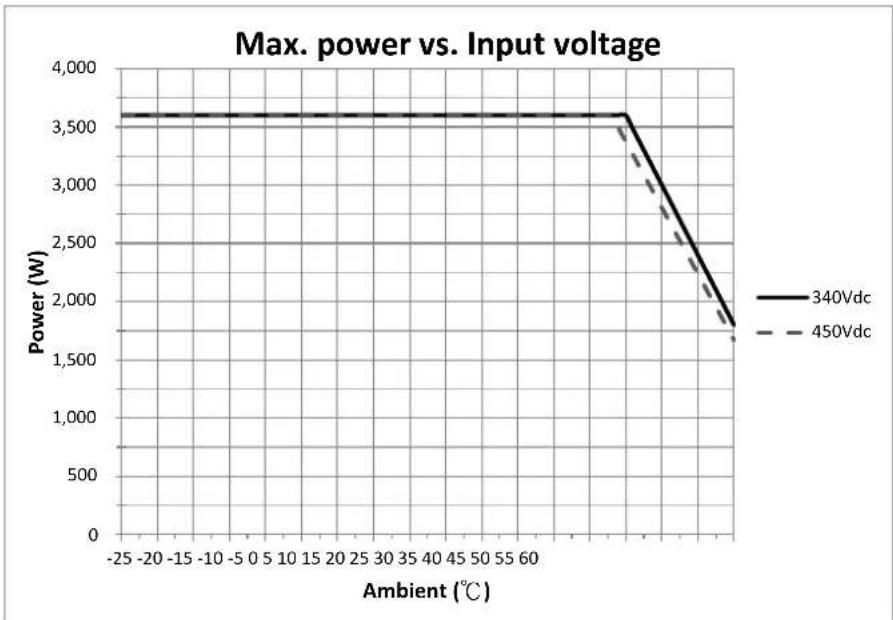
Fig. 8-2 CPSPV3600ETLA de-rating curves
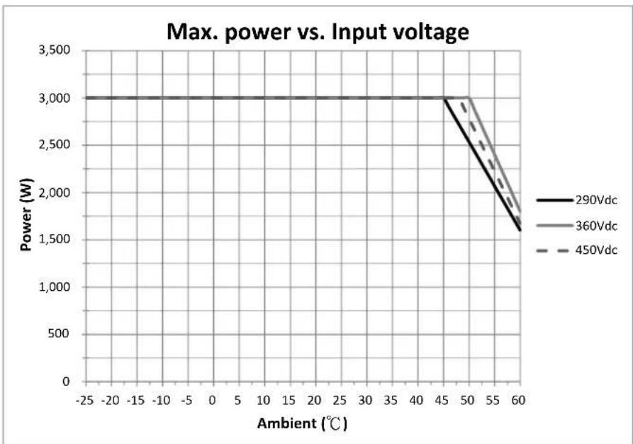
line
| Ambient (°C) | 290Vdc | 360Vdc | 450Vdc | | ------------ | ------ | ------ | ------ | | -25 | 3000 | 3000 | 3000 | | 45 | 3000 | 3000 | 3000 | | 50 | 3000 | 3000 | 3000 | | 60 | 1500 | 1750 | 1750 |Fig. 8-3 CPSPV3000ETLA de-rating curves
- Single Phase Grid-tied PV Inverter
- Contents
- Safety
- Intended to Use
- Symbols on Equipment
- Safety Information
- WARNING! High voltage from PV strings
- WARNING! High voltage due to ground fault
- WARNING! Hot surface
- WARNING! Heavy equipment
- NOTICE! Damage to the equipment due to non-sealed connector
- Introduction
- Applicability
- Scope of Delivery
- Equipment Description
- Installation
- Installation Area
- WARNING! Do not install the inverter:
- PV Array Consideration
- RNING! Check Voc of the PV strings
- Mounting the PV Inverter
- Unpack the delivery
- Mounting procedure
- WARNING! Mounting surface must be solid
- DC Wiring
- WARNING! Check the polarities of PV strings
- AC Wiring
- WARNING! Must install suitable circuit breaker for the inverter
- Wiring procedure,
- Communication Wiring
- INFORMATION! Use twisted pair wires for RS-485
- Procedure:
- Start-up
- Display, LED and Buttons
- First Start-up
- Operation
- Display Flowchart
- Troubleshooting
- Decommissioning
- Procedure
- WARNING! High voltage inside
- Technical Data
- De-rating Curves
Brand : CyberPower
Model : CPSPV6000ETLA
Category : Solar panel