
CPSPI3700EVF380 - Solar panel CyberPower - Free user manual and instructions
Find the device manual for free CPSPI3700EVF380 CyberPower in PDF.


| Product Type | Solar Pump Controller (AC Drive) |
| Brand | CyberPower |
| Model | CPSPI3700EVF380 |
| Rated Power | 3.7 kW |
| Input Voltage (PV) | Up to 750 Vdc |
| Output Voltage | 3-phase, 380-460 Vac |
| Frequency Range | 0.0 - 400.0 Hz |
| Control Method | V/F, Vector, MPPT for solar |
| Dimensions (W x H x D) | 130 x 250 x 175 mm |
| Enclosure Rating | IP20 |
| Operating Temperature | -10°C to +60°C |
| Cooling | Forced air (built-in fan) |
| Display | LED keypad with remote option |
| Communication | RS-485, Modbus, optional CANopen |
| Protection Features | Overvoltage, undervoltage, overcurrent, overheat, short-circuit |
| MPPT Efficiency | High efficiency with built-in MPPT algorithm |
| Warranty | Standard manufacturer warranty (check local distributor) |
| Maintenance | Keep clean, ensure adequate ventilation, periodic fan inspection |
| Safety Standards | EN 61800-5-1, CE, UL (check local) |
Frequently Asked Questions - CPSPI3700EVF380 CyberPower
User questions about CPSPI3700EVF380 CyberPower
0 question about this device. Answer the ones you know or ask your own.
Ask a new question about this device
Download the instructions for your Solar panel in PDF format for free! Find your manual CPSPI3700EVF380 - CyberPower and take your electronic device back in hand. On this page are published all the documents necessary for the use of your device. CPSPI3700EVF380 by CyberPower.
USER MANUAL CPSPI3700EVF380 CyberPower
Reliability. Quality. Value.
5
5
5
Solar5Controller5
CP<PI3700EVF380
CP<PI5500EVF380
User's5Manual5
5
5
5
5
Table of Contents
Chapter 1 | Safety....3
1.1 General Safety ....3
1.1.1 Usage....3
1.1.2 Receiving ....3
1.1.3 Installation .... 3
1.1.4 Wiring....4
1.1.5 Operation 4
1.1.9 Maintenance ....5
1.2 Warning Label....5
Chapter 2 | Product....7
2.1 Product Part....7
2.2 Receiving Checklist......8
2.3 Product Dimensions....9
Chapter 3 | Controller Installation....10
3.1 Installation Environment....10
3.2 Installation Direction and Spacing ....11
3.2.1 Direction....11
3.2.2 <pacing....11
3.2.3 <ide-by-<ide Installation....12
3.3 Keypad and Terminal Cover Installation....12
3.4 Wiring Protection....13
3.4.1 Controller and Input Cable....13
3.4.2 Output Cable Protection for <hort-Circuit <ituations 14
3.5 Keypad Remote Usage ....14
3.5.1 Remote Operation....15
3.5.2 External/Face-Mount 19
Chapter 4 | Wiring....17
4.1 Wiring Safety 17
4.2 Main Circuit....18
4.2.1 Main Circuit >terminal....18
4.2.2 Main Circuit Wiring 18
4.2.3 Main Circuit Cable
4.3 Control Circuit....20
4.3.1 Control Circuit >erminals....21
4.3.2 Control Circuit Wiring 23
4.3.3 Control Circuit Cable
4.3.4 Ferrule->ype >terminals....26
4.4 I/O Connections....27
4.4.1 NPN and PNP Mode
4.4.4 R<-485 Communication >ermination ON / OFF <witch 29
4.6 Wiring Checklist....31
Chapter 5 | Keypad and Parameters....32
5.1 Keypad ....32
5.1.1 %eys and Displays....32
5.1.2 %eypad Display 34
5.1.3 %eypad Programming....36
5.2 Parameter List....37
5.2.1 Parameters setting for <olar Controller 37
5.2.2 Parameters setting for the other applications 38
Chapter 6 | Troubleshooting....88
6.1 Alarm and Fault Displays 88
Chapter 1 | Safety
1.1 General Safety
<afety Information:
Warning: Indicates highly dangerous consequences such as fire, serious injury and death when failing to comply with the instructions.
Caution: Indicates dangerous consequences such as moderate injury and equipment damage when failing to comply with the instructions.
1.1.1 Usage
| Danger5 |
| >he controller is used to control the speed of 3 phase synchronous and asynchronous loads, which must not be used for single phase or other purposes. Failure to comply could cause controller damage or serious injury by fire. |
| >he controller must not be used in any medical equipment in which human life may involve. |
| >he controller is manufactured according to strict quality control standard. However, bypass the safety protection in case the controller failure causes death or serious injury. |
1.1.2 Receiving
| Warning5 |
| Do not install damaged controller or any controller without complete components inside. Failure to comply could result in accident. |
1.1.3 Installation
| Warning5 |
| Carry the controller by the bottom as carrying by the front cover may cause injury and damage from the main body of the controller falling.Attach the controller to metal or other nonflammable materials. %eep away from heat and flammable items.A control panel must have cooling fans, air vents and room for ventilation when the controller is installed inside. |
1.1.4 Wiring
| Danger5 |
| Allow only qualified electrical engineers to install the controller. Failure to comply could cause electrical shocks to personnel or damage to the controller.Ensure the power supply is off when connecting. Failure to comply could cause electrical shocks.Ensure the ground terminal PE is properly wired. Failure to comply could cause electrical shocks from the controller cover. >herefore ground the controller and for personnel safety.Do not touch the main circuit terminal. %eep the main circuit off controller cover to avoid electrical shocks.>he terminal for braking resistor is B1 and B2. Do not connect it to any other terminals. Failure to comply could cause a fire. |
| Warning5 |
| Do not connect three-phase power supply to terminals U, V and W. Failure to comply could damage the controller.An output reactor is recommended when the cable connecting between the controller and is over 100 meters. Failure to comply could result in controller damage with overcurrent caused by over-distributed capacitance.Never connect the output terminals to capacitors or unapproved LC/RC filters. Failure to comply could damage the controller components.<eparate the controller main circuit cables and control circuit cables. Failure to comply could cause interference to the control signalsEnsure the phase of power supply and rated voltage match the label on the controller. Failure to comply could controller damage. |
1.1.5 Operation
| Danger5 |
| Connect the power after completion of wiring and closing the front cover. Opening the front cover when the power is on could cause an electrical shock.%eep other personnel off the equipment when setting the controller fault restart and momentary power loss restart functions. Failure to comply could cause damage to the personnel and equipment.Once the controller is powered, the terminals are live even when controller is not in operation. >ouching the terminals could cause electrical shocks.Cancel run command before resetting the alarm and fault. Failure to comply could cause physical injury. |
| Warning5 |
| Do not start or stop the controller by connection or disconnection the power supply. Failure to comply could cause controller damage. |
| Ensure the and equipment are in proper use before operation. Failure to; comply could damage the equipment. |
| >he temperature of the braking resistor and heatsink could be very high during operation. Do not touch it or it could result in scald. |
| For lift applications, please install mechanical brakes. |
| Adjust a few parameters only if necessary as the defaults are optimum settings for most of applications. |
| Editing parameters indiscriminately could cause equipment abnormal operation. |
| Interlock the electricity supply with AC controller supply when both are available to a load. |
1.1.6 Maintenance
| Danger5 |
| Do not touch the main circuit of the controller when power is on. Failure to comply could cause electrical shocks.Disconnect the power supply before opening the front cover of the controller.Maintain the controller only when the CHARGE indicator light is off or 5 minutes after turning off power supply, so as to avoid charged capacitors causing physical injury.Allow only qualified electric engineers and electrician to maintain, repair and replace the AC controller modules. |
| Warning5 |
| >he release of breaker on the AC controller primary side could be caused by incorrect wiring, short circuit and damaged controller components. Investigate and remove the problem before reconnecting the breaker.Do not use a megger (insulation resistor) to test the controller control circuit. Failure to comply could cause controller damage. |
Notice:
All the instruction photographs and diagrams of opened controller in this manual are only for illustration. Do not attempt to operate any AC controllers with the cover opened.
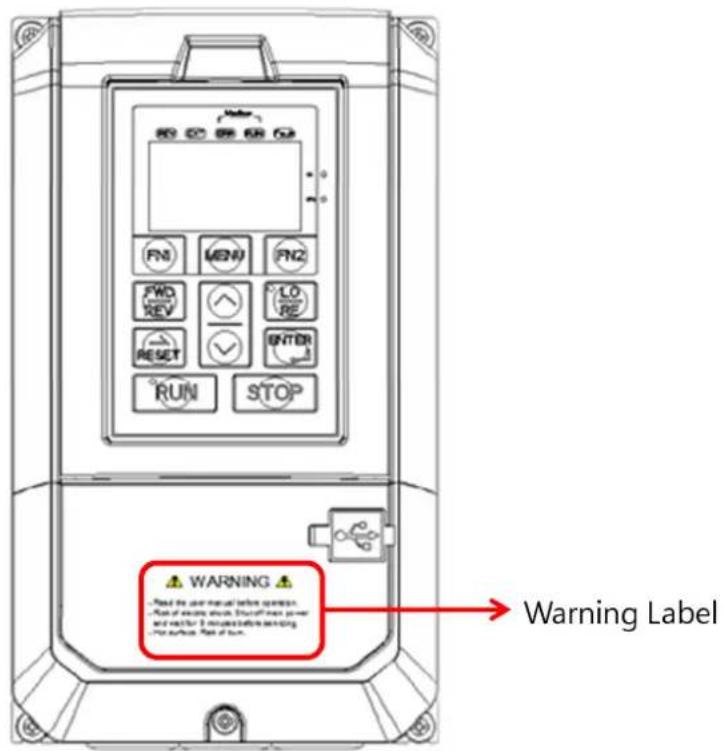
1.2 Warning Label
he warning label is on the front of the controller. Please read it carefully and follow the instructions.
- Read the user manual before operation.
Risk of electrical shock. <hut off main power and wait for 5 minutes before servicing.
■ Hot surface. Risk of burn.
Chapter 2 | Product
2.1 Product Part

A - Heatsink
B - Cooling fan
F->terminal cover screw
G - Front cover
H - U < B port
I ->erminal cover
+ - Front cover screw
% ->terminal cover screw
L-%eypad
2.2 Receiving Checklist
Check the following when receiving the controller:
| 1. Is the packaging box in good condition? Any damage or damp ?If so, contact the distributor or local CyberPower representative. |
| 2. Is the model label on the box same as what you purchased?If not, contact the distributor or local CyberPower representative. |
| 3. After opening the box, is there any damp mark inside the box? Any damage or crack on the controller enclosure?If so, contact the distributor or local CyberPower representative. |
| 4. Does the controller nameplate show the same model number as the carton label?If not, contact the distributor or local CyberPower representative. |
| 5. Are the manual and keypad in the carton?If not, contact the distributor or local CyberPower representative. |
2.3 Product Dimensions

| W W1 | H W11 D | D1 <HΦ | Φ1 Φ21 | D | 1 | ||||
| 130[5.12] | 118[4.65] | 250[9.84] | 235[9.25] | 175[6.88] | 64[2.51] | 5.2[0.20] | 5.5[0.22] | 22[0.86] | 28[1.1] |
Unit: mm/inch
Chapter 3 | Controller Installation
3.1 Installation Environment
0 ensure the optimum controller performance, install the AC controller in a proper environment specified below.
| Environment | Conditions |
| Area of Use Indoors | |
| -10°C to +60°C (IP20 enclosure)Do not install the controller in environments with wide temperature fluctuations so as to ensure the controller reliability.When the controller is installed in an enclosure cabinet, make sure the cooling works properly to keep the temperature within the specified levels.Do not allow the controller to freeze.When controllers are installed side-by-side in a cabinet, follow the instruction illustrated in Figure 3.2 to ensure the air flow. | |
| Humidity | Under 90% RHFree of condensation |
| >temperature | -20°C to +60°C |
| <urrounding Area | Free from water, oil, metal shavings or other foreign materials.Free from flammable materials (e.g., wood)Free from harmful gases and liquidsFree from direct sunlightFree from oil mist, corrosive gas, flammable gas or dust.Free from radioactive materialGreen Class 2 or above |
| Altitude | Up to 1000 m without derating. Up to 2000 meters with 1% rated current derated for every 100 m counted from 1000 m. |
| Vibration | 10 to 20 Hz at 9.8 m/s220 to 55 Hz at 5.9 m/s2 |
| Enclosure | IP20 |
3.2 Installation Direction and Spacing
3.2.1 Direction
Install the AC controller upright for better cooling.
OK

a. Upright installation
NG

b. Horizontal installation
NG
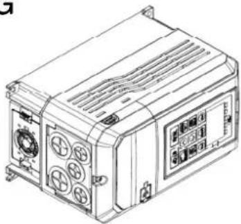
c. Transverse installation
3.2.2 Spacing
<ingle Controller Installation
Install the AC controller as illustrated below to ensure the required space for airflow and wiring.

A - Minimum 50 mm; B - Minimum 30 mm

C – Minimum 150 mm

3.2.3 Side-by-Side Installation
Install the AC controllers as illustrated below to ensure the required space for airflow and wiring.

A - Minimum 50 mm
B - Minimum 30 mm
C - Minimum 10 mm

D - Minimum 150 mm
3.3 Keypad and Terminal Cover Installation
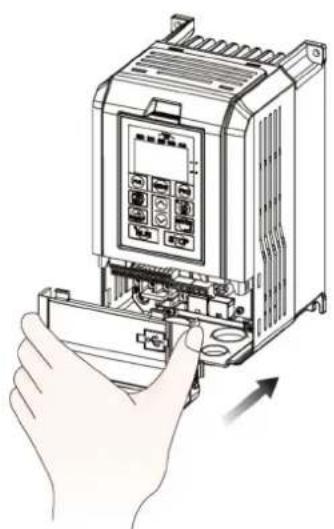
It is not necessary to remove the keypad before wiring. You just need to loosen the terminal cover screw and remove the terminal cover.
his model enclosure is non-metal. Loosen terminal cover screw and remove terminal cover for wiring. After wiring, affix the terminal cover back in position and tighten the screw. For wiring instructions and screw tightening torque please refer to Chapter 4.
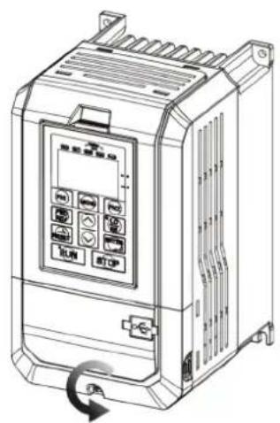
Step 1: Loosen the Screw

Step 2: Remove the Terminal Cover
Step 3: Affix the Terminal Cover After Wiring

Step 4: Tighten the Screw
3.4 Wiring Protection
3.4.1 Controller and Input Cable
Please refer to the following figure for the proper wiring, DC switch is recommended to be installed in PV input side
Note: Ensure the PV input voltage doesn't over 750Vdc at any condition, otherwise may damage the controller.

3.4.2 Output Cable Protection for Short-Circuit Situations
If the output cables are properly selected according to the controller rated current, the controller itself is fully capable of protecting the load and output cables in case of short-circuit situations.
Note: If a single controller runs more than 1 load, a separate thermal overload switch or a circuit breaker is required.5
3.5 Keypad Remote Usage
%eypad mounted on the controller can be removed and connected to the controller using an extension cable to facilitate operation when the controller is installed in a location where it cannot be easily accessed. It can also be permanently mounted remote locations such as panel doors using an extension cable and an installation support set.
3.5.1 Remote Operation
3.5.1.1 Remote Operation

3.5.2.2 Panel Cut-Out Dimensions

Chapter 4 | Wiring
4.1 Wiring Safety
| Danger5 |
| ■ >urn off all the power to the equipment before wiring. Wiring during power on could ca electrical shocks to personnel. |
| ■ Allow only qualified personnel for installation, wiring, repairing and parts replacement. |
| ■ Capacitors in the controller may still be charged for a short time after shutting off the power. Wait for the amount of time specified on the controller before any maintenance. |
| ■ Never touch input or output power cables. Do not connect any circuit to controller enclosure. |
| Warning5 |
| ■ Properly connect the loadground terminal. Contacts between the loadground terminal and loadenclosure could cause electrical shocks or a fire. |
| ■ Ensure terminal screws are all tightened. Loose connection to the main circuit could cause overheat or a fire. |
| ■ Verify if the rated voltage of the controller matches the voltage of the incoming power supply before applying power. |
| ■ Perform all wiring as specified in the wiring diagrams provided when installing braking options. Failure to comply could result in controller, braking components damage or a fire. |
| ■ Do not disconnect the loadfrom the controller while the controller is outputting voltage. |
| ■ Do not use unshielded cable for control circuit wiring. Failure to comply could cause abnormal operation of controller. |
| ■ Use shielded twisted-pair cables and connect the shield to ground terminal of the controller. |
| ■ Do not modify the controller circuits. Failure to comply could cause controller damage. |
| ■ Ensure all connections are correct after connecting the controller with other controllers. |
| ■ Rubber grommets located on conduit box shall be removed and replaced with conduit hubs in the end use installation. |
| ■ Integral solid state short circuit protection does not provide branch circuit protection. Branch circuit protection must be provided in accordance with the National Electrical Code and a additional local codes", or the equivalent |
4.2 Main Circuit
4.2.1 Main Circuit Terminal
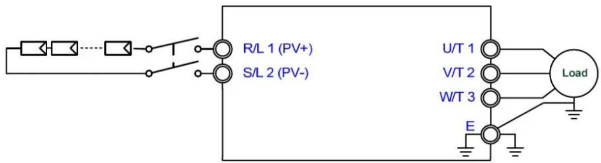
Table54.2.15Main5Circuit5Terminals5
| Terminal5Name55 | Terminal5Description5 |
| R/L1 (PV+),</L2 (PV-) | PV string input terminal |
| U/>1, V/>2, W/>3 3Ph power output terminal | |
| B1, B2, +1, +2 Do not use in solar controller application | |
| E Ground terminal | |
4.2.2 Main Circuit Wiring
4.2.2.1 PV Input Terminal
- Install a DC switch between PV string output and PV+/PV-terminal on controller. <urge protector controller is also suggested to install.
■ Connect PV input wires from string PV+/PV- to DC switch; DC switch to PV+/PV- terminal of controller.
■ Ensure the max. voltage of PV will not over 750V at any condition, or may damage the controller.
4.2.2.2 Power Output Terminal
■ Connect AC controller output terminals U/>1, V/>2 and W/>3 to loadinput terminals U, V and W respectively. Ensure the loadand controller terminals are in same phase sequence or the loadwill rotate reversely.
■ Do not connect power cable to output terminals of the controller. Failure to comply could cause controller damage and a fire.
4.2.2.4 Ground Terminal
■ Use grounding cables of dimensions regulated by electrical equipment standard.
Do not wind the grounding cable when multiple controllers are installed. Failure to comply could cause controller or equipment malfunction.
■ Ensure the neutral of the input side and controller terminal "±" are grounded according to the local electrician regulations. >N and >> system are suggested for the controller primary side.
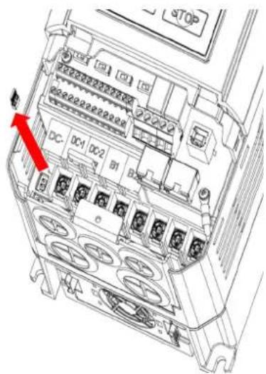
4.2.2.5 Jumper
his controller complies with the European LVD standard EN 61800-5-1 (2007) reducing the current leakage to below 10mA DC under testing condition regulated by IEC 60990 (1999).
■ Follow the instructions below to remove the jumper if an even lower current leakage to a even lower level.
■ Removing the jumper may increase the signal interference.
4.2.3 Main Circuit Cable Size and Tightening Torque
-
he recommended cables are 600 V vinyl-sheathed cables which have continuous temperature tolerance up to 75°C with ambient temperature tolerance up to 40 °C, wiring distance up to 100 meters and conditions suitable for on Normal Duty mode.
-
terminal +1, +2, B1 and B2 are only for connecting DC reactor and braking resistor options. Do not connect it to other controllers.
- Consider the amount of voltage drop when selecting cable sizes. Increase the cable size when the voltage drop exceeds 2% of the Load Rated voltage. >he amount of voltage drop can be calculated using the following formula:
Line drop voltage (V) = 3 × cable resistance (Ω/km) × cable length (m) × current (A) × 10 -3
Table54.2.25 Cable5Size5and5Tightening5Torque58Three-phase54005V)5
| Controller Rating | >terminal | Asia UApplicableApplicable>terminal>ightening CableApplicableCableApplicableCable>orque Nm (lb.in.) | >terminal>orque Nm (lb.in.) | ||||||
| ApplicableCableApplicableCableApplicable>thread | ApplicableCableApplicableCable>orque Nm (lb.in.) | ApplicableCableApplicableCable>orque Nm (lb.in.) | ApplicableCableApplicableCable>orque Nm (lb.in.) | ApplicableCableApplicableCable>orque Nm (lb.in.) | ApplicableCable>orque Nm (lb.in.) | ||||
| 3.7kW | R, <, U, V, W, PE | 5.3 | 5.3 to 8.4 | 10 10 | to 8 | 5.3 | 5.3 to 8.4 | M4 | 1.57(13.9) |
4.3 Control Circuit
■ Multi-function analog input <1 to <8 can be switched between <ink (NPN) mode and
■ +V and -V are for analog auxiliary power. Do not connect +V with -V.
■ Analog output is used to connect a frequency meter, current meter, voltage meter and power meter.
4.3.1 Control Circuit Terminals
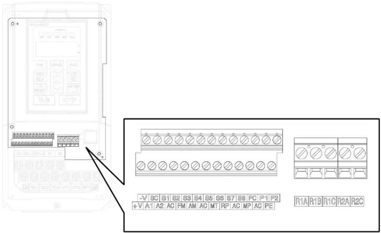
4.3.1.1 Input Terminals
Table54.6.1.15Control5Circuit5Input5Terminal555
| >terminal >ype | >terminal Code | >terminal Name >terminal Description | |
| Multi-Function Digital Inputs | <1 Digital input terminal 1 (forward/stop) | Photocoupler, 24 V, 8 mA.Use NPN/PNP switch to select multi-function digital input type.>he default is NPN mode. | |
| <2 Digital input terminal 2 (reverse/stop) | |||
| <3 Digital input terminal 3 (external fault 1) | |||
| <4 Digital input terminal 4 (fault reset) | |||
| <5 | Digital input terminal 5 (multi- step speed 1) | ||
| <9 | Digital input terminal 9 (multi- step speed 2) | ||
| <7 Digital input terminal 7 (+og command) | |||
| <8 | Digital input terminal 8 (baseblock (normal open)) | ||
| <C | Digital input common terminal for NPN/PNP mode switch. | ||
| Multi-Function Analog Inputs | +V Auxiliary power terminal +10V Analog input power+10V | ||
| -V Auxiliary power terminal -10V Analog input power-10V | |||
| A1 | Analog input terminal 1(main frequency command) | Voltage input0 to 10V / -10V to +10V | |
| A2 | Analog input terminal 2(auxiliary frequency command) | Voltage or current input(0 or 4 to 20mA, 0 to 10V, 0 to 5V | |
| PE Ground terminal | >he ground terminal for contro signals to avoid interference.Use shielded cables only. | ||
| AC Common terminal for analog signals | |||
| M> Loadtemperature signal terminal | Connects the temperature sensor of AC loadfor the controller to know the loadtemperature and trigger necessary protections. | ||
| Pulse >rain Inputs | RP | Pulse train input(frequency command) | Input frequency up to 32KHz |
| PC Common terminal for pulse train signals | |||
4.3.1.2 Output Terminals
Table54.6.1.25Control5Circuit5Output5Terminals555
| >terminal >ype | >terminal Code | >terminal Name | >terminal Description |
| Multi-Function Relay Output | R1A | Relay 1 normal open | Relay outputDC 30 V, 3 AAC 250 V, 5 A |
| R1B | Relay 1 normal closed | ||
| R1C | Relay 1 common | ||
| R2A | Relay 2 normal open | ||
| R2C | Relay 2 normal closed | ||
| Multi-Function Photocoupler Output | D1 | Photocoupler Output terminal 1 (zero speed) | Photocoupler Output48 V, 2 to 50 mA |
| D2 | Photocoupler Output terminal 2 (speed agree) | ||
| DC Photocoupler Output terminal | |||
| Multi-Function Analog Output | FM | Programmable analog output terminal (output frequency) | Voltage Output0 to 10V, -10 to +10V |
| AM | Multi-function analog output terminal (output current ) | Voltage or current output (Selectable) 0 or 4 to 20mA, 0 to 10V | |
| AC Analog common terminal | |||
| Multi-Function Pulse Train Output | MP | Multi-function pulse train output ( output frequency) | 32KHz Max |
| PC Pulse train common terminal | |||
<1> Do not assign frequent switching functions such as ON/OFF to terminals R1 and R2, which may shorten the relay terminal life.
4.3.2 Control Circuit Wiring
The applicable functions in parameter Group E can be assigned to multi-function digital inputs (S1 to S8), multi-function relay outputs (R1, R2), multi-function digital outputs (D1, D2), multi-function analog input (A1, A2) and multi-function analog output (FM, AM). The default settings are listed in Figure 4.3.1.1 and Figure 4.3.1.2.
For safety, always check the emergency stop operation after wiring. Emergency stop circuit is necessary to stop the controller immediately in a safe manner to prevent any injuries.
■ Do not remove the controller covers or touch the circuit boards when the power is on. Failure to comply could cause electrical shocks to personnel.
Separate control circuit wiring from main circuit wiring and other power lines. Failure to comply could cause controller malfunction.
■ Insulate shielded cable with tape to avoid contact with equipment and other signal lines. Improper insulation could cause controller or equipment malfunction.
■ Always use shielded twisted-pair cables to prevent controller and equipment malfunction cause by electrical interference.
■ Ground the shield to the ground terminal of controller. Failure to comply could cause erroneous operation or damage to the controller and equipment. Wire ground terminal and main circuit terminals before wiring control circuit terminals.
4.3.2.1 Digi Input Connection for PLC
![graph TD A["Digi Input Connecting 1"] --> B["PLC (High Active/Source/PNP)"] A --> C["External Power Supply"] B --> D["LOAD"] C --> D D --> E["SC (24V)"] F["Source(PNP)"] --> G["NPN/PNPS Switch"] H["Sink(NPN)"] --> I["SC (24V)"] J["Y0-Y7"] --> K["COM0/V0-Y5-Y6-Y7"] L["DC24V-DC0V"] --> M["Load"] style…](/content/2026/05/942306/images/5848d431b785df991feaa65152738b673f8e669c794f7f4ff6796990b75375bc.jpg)
![graph TD A["Digi Input Connecting 2"] --> B["Source(PNP)"] B --> C["NPN/PNPS Switch"] C --> D["SC(0V)"] D --> E["EVO8000"] F["External Power Supply"] --> G["LOAD"] G --> H["PLC (Low Active/Sink/NPN)"] H --> I["DC24V"] H --> J["DC0V"] K["Y0"] --> L["S1"] M["Y1"] --> N["S2"] O["Y2"] --> P["S3"] Q["Y3"…](/content/2026/05/942306/images/9c2ee7609009729adeccbcae54176efdd1335aac8577fc95f80640f80589aead.jpg)
4.3.2.2 Digi Input Connection for Water Tower and/or Well
When user wants to use float switch in water tower and/or well to control on/off, please connect the digi inputs to switches and set the parameters as below.
Note: >he switch type for tower and well application is A type (NO) and B type (NC) respectively.
| Parameter5 | Value55 | Application58with5tower5and5well)5 |
| b1-01 4 |   | |
| E1-00 197 | ||
| E1-01 198 | ||
| E1-02 194 | ||
| E1-03~07 20 | ||
| Parameter5 | Value55 | Application58with5either5tower5or5well)5 |
| b1-01 4 | 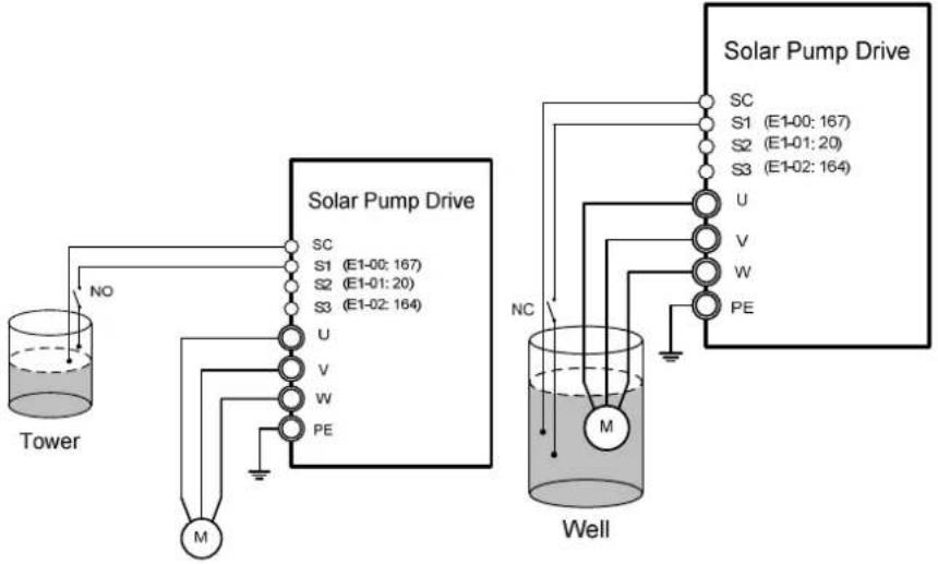 | |
| E1-00 197 | ||
| E1-01 198 | ||
| E1-02 194 | ||
| E1-03~07 20 |
4.3.3 Control Circuit Cable Size and Tightening Torque
Table54.6.6.15 Cable5Size5and5Tightening5Torque5
| >terminal | >ightening >orque Nm (lb.in.) | Bare Cable Ferrule->ype>terminal | Cable >ype | ||||
| ApplicableApplicable | ApplicableApplicable | Applicable | Cable >ype | ||||
| <1, <2, <3, <4, <5, <6, <7, <8,, RP, PE, DC, D1,D2 | M2 | 0.23(2.0) | 0.13 to 1.31(26 to 16) | 0.13(26) | 0.13 to 0.33(26 to 22) | 0.13(26) | |
| R1A, R1B, R1C, R2A, R2C | M2.6 | 0.59(5.2) | 0.13 to 2.08(26 to 14) | 0.13(26) | 0.13 to 0.33(26 to 22) | 0.13(26) | |
4.3.4 Ferrule-Type Terminals
Always use ferrule-type terminals with insulated sleeves. Refer to >able 4.3.3.2. for dimensions. In addition, crimping tool CRIMPFOX ZA-3 manufactured by Phoenix Contact is recommended.
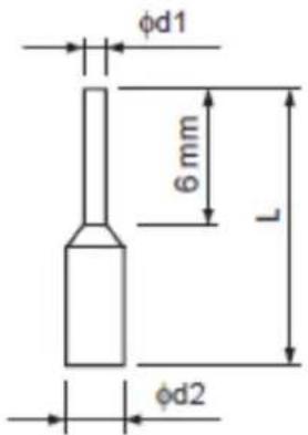
Table54.6.6.25Ferrule-Type5Terminal5Models5and5Sizes5
| Cable <ize mm2 ( AWG) | >ype | L ( mm) | d1 ( mm) | d2 ( mm) | Manufacturer |
| 0.25 ( 24) AI 0. | 25-6YE 10.5 0.8 | 2 Phoenix Contact | |||
| 0.34 ( 22) AI 0. | 34-6>= 10.5 0.8 | 2 Phoenix Contact | |||
| 0.5 ( 20) | AI 0.56-WH | 14 | 1.1 | 2.5 | Phoenix Contact |
4.4 I/O Connections
4.4.1 NPN and PNP Mode Selection
Use <ink/<source DIP switch on the control board to set NPN/PNP mode for multi-function digital inputs <1 to <8. (Default: NPN mode)

Figure 4.4.1 Sink/Source DIP Switch
4.4.2 Terminal A2 Voltage/Current Input Selection
<elect voltage or current input at terminal A2
-
o select current as the input type, set DIP switch A2 to I and set parameter E3-09 to 0 (0 to 20 mA) or 1 (4 to 20 mA).
-
o select voltage as the input type, set DIP switch A2 to V and set parameter E3-09 to 2 (0 to 10 V) or 3 (0 to 5 V).

Figure 4.4.2 DIP Switch A2
Table 4.4.1 DIP Switch A2 Settings 8Terminal A2)
| V Voltage input (0 to 10 V or 0 to 5 V) | |
| I Current input (4 to 20 mA or 0 to 20 mA) (default) | |
Table 4.4.2 Parameter E3-06
| No. | Parameter Name Description | Default | |
| E3-09 | >terminal A2 <signal Level<election | <elects the signal level for terminal A2.0: 0~20 mA1: 4~20 mA2: 0~10 V3: 0~5 V | 0, 1, 2, 3 1 |
4.4.3 Terminal AM Voltage/Current Output Selection
<elect voltage or current output type for terminal AM
-
o select voltage as the output type, set DIP switch AM to V and set parameter E4-04 to 0 (0 to 10 V).
-
o select current as the output type, set DIP switch AM to I and set parameter E4-04 to 1 (0 to 20 mA) or 2 (4 to 20 mA).

Figure 4.4.3 DIP Switch AM
Table344436BD1B56WchtoA5AM5Setting58Terminal5AM)555
| V Voltage output (0 to 10 V) | |
| I Current output (4 to 20 mA or 0 to 20 mA) | (default) |
5
Table54.4.45Parameter54-045
| No Parameter Name Description | Default | |||
| E4-04 | >terminal AM <signal Level<election | 0, 1, 2 2 | ||
4.4.4 RS-485 Communication Termination ON / OFF Switch
he default of termination resistor for R<-485 communication is OFF. <witch it to ON when the controller is the last in a series of slave controllers. <et this termination resistor on DIP switch R<485 illustrated in Figure 4.4.4.

Figure 4.4.4 DIP Switch RS-485 Termination Resistor
4.6 Wiring Checklist
Table 4.6 Wiring Checklist
| ☐ | No. | Item | Page |
| Power Supply Voltage and Output Voltage | |||
| ☐ | 1 | Power supply voltage is within the voltage range of specified controller input. | |
| ☐ | 2 | >he loadvoltage matches the controller output specifications. | |
| ☐ | 3 | >he controller rating matches the loadrating. | |
| Main Circuit Wiring | |||
| ☐ | 4 | An MCCB of proper specifications is connected between the controller and load. | |
| ☐ | 5 | Power cables are correctly connected to controller input terminals R/L1,,/L3. | |
| ☐ | 6 | Loadterminals and controller terminals U/>1, V/>2 and W/>3 are in same phase sequence. (Otherwise the loadwill rotate reversely) | |
| ☐ | 7 | Power supply and loadpower cable complies with electrician regulations. | |
| ☐ | 8 | >he controller is properly grounded. | |
| ☐ | 9 | Controller terminal screws of the main circuit and ground are tightened. | |
| ☐ | 10 | An MC is installed for each loadif a single controller runs more than one load Note: Note: | |
| ☐ | 11 | When using a braking resistor or braking unit, an MC is installed on the controller input side and able to shut off the power to controller when overloaded. | |
| Control Circuit Wiring | |||
| ☐ | 12 | >wisted-pair cables are used for all controller control circuit wiring. | |
| ☐ | 13 | ||
| ☐ | 14 | Options (if any) are properly installed. | |
| ☐ | 15 | No wiring mistakes. | |
| ☐ | 16 | Do not use a buzzer to check wiring. | |
| ☐ | 17 | >he control circuit terminal screws are tightened. | |
| ☐ | 18 | No cable clippings or screws are left inside the controller enclosure. | |
| ☐ | 19 | Control circuit wiring and main circuit wiring are separated. | |
Chapter 5 | Keypad and Parameters
5.1 Keypad
Use the keypad to enter RUN and <>OP commands, display data, fault, alarm and set parameters. >he keypad of EVO 8000 series can be removed and connected to the controller using an extension cable. >he remote keypad can be mounted on control panels with screws thread M4 X P0.7 and the screw length longer than the thickness of panel door.
5.1.1 Keys and Displays

Figure 5.1.1 Keypad
Table 5.1.1 Keypad Keys and Displays
| No | Display | Name | Function |
| 1 |  | FN1 Key | User-defined function key for Quick Setting Mode |
| 2 |  | FWD/REV Key | Forward/reverse selection |
| 3 |  | RESET Key | Moves the cursor to the right Resets the controller to clear a fault situation |
| 4 |  | RUN Key | Runs the controller |
| 5 |  | MENU Key | Enters or exits the parameter group Switches the displayed menu |
| 6 |   | UP/DOWN Key | Selects parameter numbers, increments and decrements setting value and frequency |
| 7 |  | STOP Key | Stops the controller |
| 8 |  | ENTER Key | Enters parameter value, parameter and setting Enters parameter setting menu. |
| 9 |  | LO/RE Selection Key | Switches controller control between the keypad (LOCAL) and an external source (REMOTE) |
| 10 |  | FN2 Key | Retain |
| 11 |  | RUN Light | Refer to Table 5.1.2.2 |
| 12 |  | LO/RE Light | Refer to Table 5.1.2.2 |
| 13 |  | RPM Light | Refer to Table 5.1.2.2 |
| 14 |  | Hz Light | Refer to Table 5.1.2.2 |
| 15 |  | Fault Light | Refer to Table 5.1.2.2 |
| 16 |  | Modbus RUN Light Refer to >able 5.1.2.2 |
| 17 |  | Modbus ERR Light Refer to >able 5.1.2.2 |
| 18 |  | EX> Light Refer to >able 5.1.2.2 |
| 19 |  | REV Light Refer to >able 5.1.2.2 |
5.1.2 Keypad Display
5.1.2.1 LED Display
Table 5.1.2.1 LED Display
| Number /Letter | LED Display | Number /Letter | LED Display | Number /Letter | LED Display | Number /Letter | LED Display |
| 0 |  | 9 |  | i | r |  | |
| 1 | A |  | + |  | < |  | |
| 2 |  | b |  | % | t | ||
| 3 |  | c |  | L |  | U |  |
| 4 | d |  | M | v | |||
| 5 |  | E | n | W | Nil | ||
| 6 | F | o | X | Nil | |||
| 7 |  | G |  | P |  | y | Nil |
| 8 |  | H |  | q | Nil | Z | Nil |
5.1.2.2 LED Indication
Table 5.1.2.2 LED Indication
| Indicator Light | Lit Blinking Off | ||
 | Controller in operation | Controller in decelerationOutput frequency below the minimum frequency | Controller not in operation |
 | Control from Local Nil | Control from Remote | |
 | Displaying output speed | Nil Nil | |
 | Displaying output frequency | Nil Nil | |
 | During fault Nil Normal operation | ||
 | Communication connected | Nil Nil | |
 | Communication error Nil Nil | ||
 | Allows Run commands only from a remote source | Nil | Allows Run commands only from keypad |
 | Rotating reversely Nil | Nil | |
5.1.3 Keypad Programming
%eypad Display Menu <tructure
![graph TD A["060.00"] -->|MENU| B["R1"] B -->|ENTER| C["R1-00"] C -->|ENTER| D["00000"] D -->|ENTER| E["End"] B -->|MENU| F["R1-01"] F -->|UP/DOWN/RESET| G["b1"] G -->|UP/DOWN/RESET| H["R1-01"] H -->|UP/DOWN/RESET| I["00001"] I -->|UP/DOWN/RESET| J["(1sec)"]](/content/2026/05/942306/images/98581165fbd91ea99cc5c6adee3fe3c8dce44fde3e7b4a2b18e1a2f2053f7e4b.jpg)
=quick setting mode: User must assign the function to the FN1 key in advance so as to quickly set the parameter by pressing FN1 key.
![graph TD A["06000"] -->|FN1| B["b"] B -->|FN1| C["0"] B -->|ENTER| D["00000"] D -->|ENTER| E["End"] E -->|(1 sec)| B B -->|MENU| F["00001"] F -->|UP/DOWN/RESET| G["0606"] G -->|UP/DOWN/RESET| H["00001"]](/content/2026/05/942306/images/202ecd8523e206a40fc2796da99e85d1772e98e8b3663a1b58e4e15f7f4e21f9.jpg)
=quick monitor mode: Press FN2 key to quickly monitor part of the parameters and press UP and Down key to switch the parameter.
![graph TD A["060.00"] --> B["FN2"] B --> C["800.32"] C --> D["U1-03 (Output Current)"] D --> E["FN2"] E --> F["800.0"] F --> G["U1-06 (Main Circuit DC Voltage)"] G --> H["FN2"] H --> I["800.0"] I --> J["U1-05 (Output Voltage)"] J --> K["FN2"] K --> L["444.0"] L --> M["U1-04 (Motor Speed)"] M --> N["F…](/content/2026/05/942306/images/db9913bcf7eb7df2c42cf32802586a788f1bc9f6c262b89d59f691d142f636bf.jpg)
During-operation setting mode: Controller frequency is adjustable during operation in Local mode

5.2 Parameter List
5.2.1 Parameters setting for Solar Controller
| Parameter | Name Description | Option Default | |
| A1-03 Initialization 2838: 2-Wire | |||
| <9-00 M PP> Mode Enable 1:E | Enable/ 0: Disable 1 | ||
| <9-01 | Controller Min.Operating Voltage | Controller starts when input voltage(DC) higher than this value. | 350 |
| <9-02 <tarting Frequency <tart to operate from this frequency 20 | |||
| <9-04 M PP> Voltage <tep Delta output voltage per MPP> step 4 | |||
| <9-05 | Min. Operating Frequency | Controller min. operating frequency, shutdown if operating frequency is lower this this vale | 15 |
| <9-09 M | > | >he regular duration between MPP> commandsUnit: 20ms | 30 (0.9s) |
| b1-00 | Frequency Command source | 0: %eypad1: Control Circuit >erminal (Analog Input)2: >erminal Up/Down3: Modbus Communication4: Pulse >rain Input (Including PWM signal5: MPP> | 5 |
| b1-01 | Operating Command | 4: >erminal5: Auto | 5 |
| b1-02 | Stopping Method Selection | 0: Ramp to Stop1: Coast toimer | 1 |
| C1-00 Acceleration >ime Controller acceleration >ime. Unit: s 3 | |||
| C1-01 Deceleration >ime Controller deceleration >ime. Unit: s 0.1 | |||
| P2-03 UV protection Under voltage protection level. Unit: s 300 | |||
| E1-00 >terminal <1 Function | Digi input <1,197: Controller stop when water gage(sensor) open | 197 | |
| E1-01 >terminal <2 Function | Digi input <2, default is disable (no function) 20 | ||
| E1-02 >terminal < Function 3 | Digi input <3, Digi input <3,194: Operation pause when terminal close | 194 | |
| E1-03~07 | >terminal <4~<8 Function | Digi input <4~<8 default is disable (no function) | 20 |
5.2.2 Parameters setting for the other applications
| Parameter | Name | Description | Setting Range | ||||||||
| Group A, Initialization | |||||||||||
| A1: Basic Settings | |||||||||||
| A1-01<4> | Access LevelSelection | Selects access level (edit /view)0: View OnlyAccess to only parameter A1-011: User-Defined Parameter AccessAccess to only parameter A1-01 and A2-00 to A2-312: All Parameter AccessAll parameters can be edited and viewed | Default: 2Range: 0, 1, 2 | ||||||||
| A1-02 | Control Method Selection | 0: Open-Loop V/F Control1: Closed-Loop V/F Control2: Open-Loop Vector Control3: Closed-Loop Vector Control4: PM Open-Loop Vector Control5: PM Closed-Loop Vector Control6: Closed-Loop Torque Control7: Position Control | Default: 0Min.: 0Max.: 7 | ||||||||
| A1-03 | Reset | Resets parameter settings to defaults. After resetting parameters, the value will become 0.2538: Resets 2-Wire Sequence/ 50Hz / 380V2541: Resets 2-Wire Sequence / 50Hz / 415V2544: Resets 2-Wire Sequence / 50Hz / 440V2546: Resets 2-Wire Sequence / 50Hz / 460V2638: Resets 2-Wire Sequence / 60Hz / 380V2641: Resets 2-Wire Sequence / 60Hz / 415V2644: Resets 2-Wire Sequence / 60Hz / 440V2646: Resets 2-Wire Sequence / 60Hz / 460V3538: Resets 3-Wire Sequence / 50Hz / 380V3541: Resets 3-Wire Sequence / 50Hz / 415V3544: Resets 3-Wire Sequence / 50Hz / 440V3546: Resets 3-Wire Sequence / 50Hz / 460V3638: Resets 3-Wire Sequence / 60Hz / 380V3641: Resets 3-Wire Sequence / 60Hz / 415V3644: Resets 3-Wire Sequence / 60Hz / 440V3646: Resets 3-Wire Sequence / 60Hz / 460V | Default: 0Range: 0 to 3646 | ||||||||
| A1-04 | Password | Set password to parameter A1-05 and enter the password to parameter A1-04 to unlock it.Parameters A1-01 to A1-03, A1-06, A2-01 to A2-32 cannot be edited until correct password is entered to A1-04 | Default: 0000Min.: 0000Max.: 9999 | ||||||||
| A1-05 | Password Setting | ||||||||||
| A1-06 | ND/HD Selection | 0: Heavy Duty (HD)1: Normal Duty (ND) | Default: 0Range: 0, 1 | ||||||||
| A2: User-Defined Parameters | |||||||||||
| A2-00 to A2-31 | User-Defined Parameters 1 to 32 | Selects up to 32 parameters and assigns them to parameter A2-00 to A2-31. Saved parameters | Range: A1-00 to F1-18 | ||||||||
| can be viewed in User-Defined Parameter Access. To assign specific parameters to A2-00 to A2-31, set parameter A1-01 to 2. The saved parameters A2-00 to A2-31 can only be viewed if A1-01 is set to 1 | |||||||||||
| Parameter Default | Name | Parameter | Default | Name | |||||||
| A2-00 b1-00 | Frequency Command Selection | A2-16 | E3-07 | Terminal A2 Function Selection | |||||||
| A2-01 b1-01 | Run Command Selection | A2-17 | |||||||||
| A2-02 C1-00 | Acceleration Times | A2-18 | |||||||||
| A2-03 C1-01 | Deceleration Times | A2-19 | |||||||||
| A2-04 C3-00 | Torque Compensation Gain | A2-20 | |||||||||
| A2-05 d1-02 | Maximum Output Frequency | A2-21 | |||||||||
| A2-06 d1-03 | Maximum Voltage | A2-22 | |||||||||
| A2-07 d1-04 | Base Frequency | A2-23 | |||||||||
| A2-08 d1-05 | Base Voltage | A2-24 | |||||||||
| A2-09 a2-06 | Operation Direction at Power Up when Using Keypad | A2-25 | |||||||||
| A2-10 b1-10 | Run Command at Power up | A2-26 | |||||||||
| A2-11 E2-00 | Relay 1 Function Selection | A2-27 | |||||||||
| A2-12 E2-01 | Relay 2 Function Selection | A2-28 | |||||||||
| A2-13 E3-00 | Terminal A1 Signal Level Selection | A2-29 | |||||||||
| A2-14 E3-01 | Terminal A1 Function Selection | A2-30 | |||||||||
| A2-15 E3-06 | Terminal A2 Signal Level Selection | A2-31 | |||||||||
| A2-32 | User-Defined Parameter Automatic Save | Saves the most recently edited parameters. 0: Do not save list of recently edited parameters 1: Save list of recently edited parameters | Default: 1Range: 0, 1 | ||||||||
| Group b, Application | |||||||||||
| b1: Operation Mode Selection | |||||||||||
| b1-00 | Frequency Command Selection 1 | 0: Keypad1: Control Circuit Terminal (Analog Input)2: Terminal Up/Down3: Modbus Communication4: Pulse Train Input (Including PWM signal | Default: 1Min.: 0Max.: 5 | ||||||||
| input)5: Option Card | |||||||||||
| b1-01 | Run Command Selection 1 | 0: Keypad1: Control Circuit Terminal (Sequence Control Input)2: Modbus Communication3: Option Card | Default: 1Range: 0, 1, 2, 3 | ||||||||
| b1-02 | Stopping Method Selection | 0: Ramp to Stop1: Coast to Stop2: DC Braking to Stop3: Coast to Stop with Timer | Default: 0Min.: 0Max.: 3 | ||||||||
| b1-03 | Reverse Rotation Selection | 0: Reverse Rotation EnabledController accepts a run command of both forward and reverse directions1: Reverse Rotation disabledController can accept only run command of forward direction | Default: 0Range: 0, 1 | ||||||||
| b1-04<9> | Zero-speed mode function | When the frequency command lower than the set value of the d1-08, and the operation command also exists when the load deceleration and lower than d1-08 setting value, the zero-speed operation | Default: 0Range: 0, 1 | ||||||||
| b1-05 | Run Command Action after Switch | 0: Ignore Active Run Command at the New SourceIf a Run command at the new source is active, the controller will not start or the controller will stop operation if it was running when switching from the old source to the new source. The controller can start only when the Run command is removed and given again.1: Accept Active Run Command at the New SourceIf a run command at the new source is active, the controller will accept it and run the load immediately right after switching from the old source to the new source. | Default: 0Range: 0, 1 | ||||||||
| b1-06 | Run Command Selection during Programming | 0: Run command disabled during Programming1: Run command enabled during Programming2: Prohibit programming during runThe programming mode cannot be displayed during run except for monitoringparameter Group U. | Default: 0Range: 0, 1, 2 | ||||||||
| b1-07 | FrequencyCommandSelection 2 | Enabled while E1-00 to E1-07 is set to 4 and the DIP switch is set to OFF0: Keypad1: Control Circuit Terminal (Analog Input)2: Terminal Up/Down3: Modbus Communication4: Pulse Train Input (Including PWM signal input)5: Option card | Default: 0Min.: 0Max.: 5 | ||||||||
| b1-08 | Run CommandSelection 2 | Enabled while E1-00 to E1-07 is set to 4 and the DIP switch is set to OFF0: Keypad1: Control Circuit Terminal (Sequence Control Input)2: Modbus Communication3: Option card | Default: 0Range: 0, 1, 2, 3 | ||||||||
| b1-09<7> | FrequencysuperpositionSelection | 0: Disabled1: Enabled | Default: 0Range: 0, 1 | ||||||||
| b1-10 | Run Command atPower up | Determines to accept or ignore an active Run command from Remote during power up.0: IgnoreController ignores an active run command during power up1: AcceptController accepts an active run command at power up and runs the load immediately. | Default: 0Range: 0, 1 | ||||||||
| b1-12<7> | Local/ Remoteswitching Enableduring Operating | 0 :Disabled1 :Enabled | Default: 0Range: 0, 1 | ||||||||
| b2: DC Braking | |||||||||||
| b2-00 | Zero SpeedHolding (DCBraking) Start Level | Sets the start frequency for Zero Speed Holding (DC braking). Enabled when b1-02 (Stopping Method Selection) is set to 0 (Ramp to Stop) | Default: 0.5HzMin.: 0.0 HzMax.: 10.0 Hz | ||||||||
| b2-01 | DC Braking Current | Sets the DC braking current as a percentage of the controller rated current | Default: 30%Min.: 0%Max.: 100% | ||||||||
| b2-02 | DC Braking Time atStart | Sets the DC braking time at start to stop a coasting load before restarting it or to applybraking torque at start when high starting torque is needed. Disabled when set to 0.00. | Default: 0.00 sMin.: 0.00 sMax.: 99.99 s | ||||||||
| b2-03 | DC Braking Time at Stop | Sets the DC braking time at stop to stop a load rotating with high inertia. Disabled when set to 0.00. | Default: 0.50s Min.: 0.00s Max.: 99.99s | ||||||||
| b3: Speed Search | |||||||||||
| b3-00 | Speed Search Setting | 0 :Disabled1 :Enabled and searched from the highest frequency2 : Enabled and searched from the frequency command3 :Retain4 :Retain | Default: 0 Range: 0, 1, 2 | ||||||||
| b3-01 | Speed Search Operating Current | Sets the current level as a percentage of the controller rated current below which Speed Search is deactivated. | Default: 80% Min.: 0 % Max.: 100% | ||||||||
| b3-02 <9> | Voltage Rocevery Time | Sets the search speed in the output voltage restoring to the time set v / f voltage curve required | Default: 0.6s Min.: 0.3s Max.: 5.0s | ||||||||
| b3-03 | Retain | ||||||||||
| b3-04 <9> | Speed search deceleration time | Sets the search speed in the deceleration time (The maximum output frequency to the minimum output frequency deceleration time) | Default: 2.0s Min.: 0.1s Max.: 10.0s | ||||||||
| b3-05 <9> | Search speed in V / f | In order to reduce the speed of search output current by the V / f curve calculated by multiplying the voltage set value b3-05 by adjusting the setting, the speed can be suppressed search output current. | Default: 100% Min.: 10 % Max.: 100% | ||||||||
| b4: Timer Function | |||||||||||
| b4-00 | Timer Function On-Delay Time | Sets the on-delay and off-delay time to switch on/off the timer output. | Default: 0.1 s Min.: 0.1 s Max.: 3000.0 s | ||||||||
| b4-01 | Timer Function Off-Delay Time | Default: 0.0 s Min.: 0.0 s Max.: 3000.0 s | |||||||||
| b5: PID Control | |||||||||||
| b5-00 | PID Control Setting | 0 : PID Control Disabled1 : PID Control Enabled (D Control for DeviationSignal U4-01)2 : PID Control Enabled (D Control for Feedback Signal U4-05)3 : PID Control Enabled (Frequency Command + PID Output from D Controlled Deviation)4 : PID Control Enabled (Frequency Command + PID Output from D Controlled Feedback)5 : PID Control Disabled · but b5-14/b5-15 (PID Sleep) and b5-29/b5-30(PID Wake-up)Enabled | Default: 0 Min.: 0Max.: 5 | ||||||||
| b5-01<4> | Proportional Gain Setting (P) | Sets the P gain for PID input. | Default: 1.00Min.: 0.00Max.: 25.00 | ||||||||
| b5-02<4> | Integral Time Setting (I) | Deviation appears between PID target value and feedback value when using only proportional control. To reduce the deviation, set integral time (I). | Default: 1.0 sMin.: 0.0 sMax.: 360.0 s | ||||||||
| b5-03<4> | Integral Time (I)Limit Setting | Sets the maximum output from the I (integral) control as a percentage of the maximum frequency (d1-02) | Default: 100.0%Min.: 0.0%Max.: 100.0% | ||||||||
| b5-04<4> | Derivative Time (D) | Sets derivative time for D control. | Default: 0.00 sMin.: 0.00 sMax.: 10.00 s | ||||||||
| b5-05<4> | PID Output Limit | Sets the maximum output from PID control as a percentage of the maximum frequency. | Default: 100.0%Min.: 0.0%Max.: 100.0% | ||||||||
| b5-06<4> | PID Bias Voltage Adjustment | Sets the PID bias voltage adjustment as a percentage of the maximum frequency to add to the PID control output. | Default: 0.0%Min.: -100.0%Max.: 100.0% | ||||||||
| b5-07<4> | PID Primary Delay Time | Sets the delay time for the PID output filter. | Default: 0.00 sMin.: 0.00 sMax.: 10.00 s | ||||||||
| b5-08 | PID Output Selection | 0 : Normal PID Output1 : Reverse PID OutputReverses the +/- sign of the PID output | Default: 0Range: 0, 1 | ||||||||
| b5-09 | PID Output Gain | Sets a PID output gain | Default: 1.00Min.: 0.00Max.: 25.00 | ||||||||
| b5-10 | PID Output Reverse Selection | Determines whether or not a negative PID output reverses the controller rotating direction.0: Reverse Disabled1: Reverse Enabled | Default: 0Range: 0, 1 | ||||||||
| b5-11 | PID Feedback Low /High Detection Selection | 0: Multi-Function Output Only1: Feedback Low /High AlarmThe controller continues operation when an alarm is displayed)2: Feedback Low /High FaultA fault will cause the controller to stop the load.3: Multi-Function Output only when PID is DisabledSame action as b5-11=0.4: Feedback Low /High Alarm (detection disabled when PID is disabled)5: Feedback Low /High Fault (detection disabled when PID is disabled)6: Multi-Function Output (Keep running without an alarm displayed)7: Multi-Function Output Only (detection working when controller running or not) | Default: 0Min.: 0Max.: 7 | ||||||||
| b5-12 | PID Feedback Low Detection Level | Sets the PID feedback level used for detection.When the PID feedback falls below this level for longer than the time set to b5-13, PID feedback loss will be detected. | Default: 0%Min.: 0%Max.: 100% | ||||||||
| b5-13 | PID Feedback Low Detection Time | Sets the PID feedback time used for detection.When the PID feedback falls below the level set to b5-12 for longer than this time, PID feedback loss will be detected. | Default: 1.0 sMin.: 0.0 sMax.: 25.5 s | ||||||||
| b5-14 | PID Sleep Start Level | Sets the PID level to trigger the controller to sleep. | Default: 0.0HzMin.: 0.0 HzMax.: <5> | ||||||||
| b5-15 | PID Sleep Delay Time | Sets the delay time used to activate/deactivate the PID Sleep function. When this parameter is set to 0.0, PID Sleep function will be stopped. | Default: 0.0 sMin.: 0.0 sMax.: 25.5 s | ||||||||
| b5-16 | PID Command Acc./Dec. Time | Sets the PID command acceleration/deceleration time used for PID target soft-start function. | Default: 0.0 sMin.: 0.0 sMax.: 200.0 s | ||||||||
| b5-17 | PID Target Selection | 0:PID Target Disabled1:PID Target Enabled | Default: 0Range: 0, 1 | ||||||||
| b5-18 | PID Target Value | Sets the PID target value as a percentage of the maximum output frequency when b5-17=1 andno other ananlog input sets the PID Target. | Default: 0.00%Min.: 0.00%Max.: 100.00% | ||||||||
| b5-19 | PID Target Value Units | 0 : 0.01Hz1 : 0.01% (Maximum Frequency is 100%)2 : r/min. (Number of Poles must be set)3 : User Defined (Defined by b5-24 and b5-25) | Default: 1Range: 0, 1, 2, 3 | ||||||||
| b5-20<7> | PID Output Lower Limit | Sets the lower limit as a percentage of the maximum output frequency set in d1-02 for PID output. | Default: 0.0%Min.: -100.0%Max.: 100.0% | ||||||||
| b5-21<7> | PID Input Limit | The higher PID Input value is, the higher PID output value will be. Sets this parameter to limit the PID input value. | Default: 1000.0%Min.: 0.0%Max.: 1000.0% | ||||||||
| b5-22 | PID Feedback High Detection Level | Sets the level for PID feedback high detection as a percentage of the maximum output frequency.PID feedback high will be detected when the feedback exceeds the level set in b5-22 for longer than the time set in b5-23. | Default: 100%Min.: 0%Max.: 100% | ||||||||
| b5-23 | PID Feedback High Detection Time | Sets the time for PID feedback high detection.PID feedback high will be detected when the feedback exceeds the level set in b5-22 for longer than the time set in b5-23. | Default: 1.0 sMin.: 0.0 sMax.: 25.5 s | ||||||||
| b5-24 | PID Target Display Value | Sets a value to display to U4-00 and U4-03 when the controller runs at the maximum output frequency | Determined by b5-19Min.: 1Max.: 60000 | ||||||||
| b5-25 | PID Target Display Digits | Sets the number of decimal places to display.0 : No Decimal Places1 : 1 Decimal Place2 : 2 Decimal Places3 : 3 Decimal Places | Determined by b5-19Min.: 0Max.: 3 | ||||||||
| b5-26<7> | Frequency Command Display During PID | 0 : Displays frequency command after the PID compensation.1 : Displays frequency command before the PID compensation. | Default: 0Range: 0, 1 | ||||||||
| b5-27<7> | PID Output Direction 2 | Sets the direction when PID output value is minus.0 : Reverse is not allowed.1 : Reverse is allowed. | Default: 1Range: 0, 1 | ||||||||
| b5-28 | PID Disconnection Output Frequency | When a PID feedback disconnection alarm occurs, the controller will run at the frequency set to b5-28, and return to PID control when disconnection alarm is reset. | Default: 30.0 HzMin.:0.0HzMax.: Determined by d1-02, L2-00, d1-13 | ||||||||
| b5-29<9> | PID Wake-up Level | Sets the PID Wake-up level | Default:0.0 HzMin.:0.0 HzMax.:<5> | ||||||||
| b5-30<9> | PID Wake-up deley time | Sets the PID Wake-up delay time | Default: 0.0 sMin.: 0.0 sMax.: 25.5 s | ||||||||
| b6: Dwell Function | |||||||||||
| b6-00 | Dwell Frequency at Start | Sets the frequency to b6-00 used to be held for the time set in b6-01 during acceleration. | Default: Determined by A1-02Min.: 0.0 HzMax.: Determined by d1-02, L2-00, d1-13 | ||||||||
| b6-01 | Dwell Time at Start | Default: 0.0 sMin.: 0.0 sMax.: 10.0 s | |||||||||
| b6-02 | Dwell Frequency at Stop | Sets the frequency to b6-02 used to be held for the time set in b6-03 during deceleration. | Default: 0.0HzMin.: 0.0 HzMax.: Determined by d1-02, L2-00, d1-13 | ||||||||
| b6-03 | Dwell Time at Stop | Default: 0.0 sMin.: 0.0 sMax.: 10.0 s | |||||||||
| b7: Droop Function | |||||||||||
| b7-00 | Droop Control Gain | Sets the amount of speed reduction when the torque reference is 100%. The gain is set as a percentage of the maximum output frequency. A setting of 0.0% disables the Droop control function. | Default: 100%Min.: 0%Max.: 100% | ||||||||
| b7-01 | Droop Control Delay Time | Adjusts the responsiveness of Droop control. Reduce the setting if the reaction time is too long, and increase the setting if hunting occurs. | Default: 0.05 sMin.: 0.03 sMax.: 2.00 s | ||||||||
| b7-02 | Droop Control Limit Selection | 0 : Droop Control Limit Disabled1 : Droop Control Limit Enabled | Default: 1Min.: 0Max.: 1 | ||||||||
| b9 : Position Control / Zero Speed Holding <7> | |||||||||||
| b9-00 | Position Control/Zero Speed Holding Gain | Sets the response of Zero Speed Holding in FOC with PG control method or response of Position Control in Position Control control method. | Default: 5%Min.: 0%Max.: 100% | ||||||||
| b9-01 | Zero SpeedHolding Stop Width | Sets the signal output width in which the ZeroSpeed Holding function will stop. | Default: 12 pulseMin.: 0 pulseMax.: 4096 pulse | ||||||||
| b9-02 | Zero Speed Holding On/ Off | 0: Zero Speed Holding Disabled.Controller coasts to stop when the frequency is zero.1: Zero Speed Holding Enabled.Zero Speed Holding starts when the frequency is zero. The holding current is set in b2-01 and it will be limited to below 20% of the controller rated current. | Default: 0Min.: 0Max.: 1 | ||||||||
| b9-03 | Zero Speed Holding Time | Sets the Zero Speed Holding time. Controller will coast to stop when the Zero Speed Holding time is longer than this setting. Set 00.00 to disable Zero Speed Holding or set 99.99 to enable this function continuously. | Default: 0.10secMin.: 00.00secMax.: 99.99sec | ||||||||
| b9-04 | Position Control Input Command Direction | 0: Forward1: Reverse | Default: 0Min.: 0Max.: 1 | ||||||||
| Group C, Tuning | |||||||||||
| C1: Acc./Dec. Time | |||||||||||
| C1-00<4> | Acceleration Time1 | Sets the time that the controller accelerates from 0Hz to the maximum output. | Default: 10.0 sMin.: 0.0 sMax.: 6000.0 s | ||||||||
| C1-01<4> | Deceleration Time1 | Sets the time that the controller decelerates from the maximum output to 0Hz. | |||||||||
| C1-02<4> | Acceleration Time2 | Sets the time that the controller accelerates from 0Hz to the maximum output. | |||||||||
| C1-03<4> | Deceleration Time2 | Sets the time that the controller decelerates from the maximum output to 0Hz. | |||||||||
| C1-04<4> | Acceleration Time3 | Sets the time that the controller accelerates from 0Hz to the maximum output. | |||||||||
| C1-05<4> | Deceleration Time3 | Sets the time that the controller decelerates from the maximum output to 0Hz. | |||||||||
| C1-06<4> | Acceleration Time4 | Sets the time that the controller accelerates from 0Hz to the maximum output. | |||||||||
| C1-07<4> | Deceleration Time4 | Sets the time that the controller decelerates from the maximum output to 0Hz. | |||||||||
| C1-08 | Fast Stop Time | Sets the time to stop the controller faster. | |||||||||
| C1-09 | Acc./Dec. Time Unit Selection | Set the units of time for C1-00 to C1-08. 0 : 0.01 s (0.00 to 600.00 s) 1 : 0.1 s (0.00 to 6000.0 s) | Default: 1 Range: 0, 1 | ||||||||
| C1-10 | Acc./Dec. Time Switch Frequency | Sets the frequency level. The controller will switch the acceleration and deceleration time at this level. | Default: 0.0 Hz Min.: 0.0 Hz Max.: Determined by d1-02, L2-00 | ||||||||
| C1-11 | Jog Acc. Time | Sets the time to accelerate from 0 Hz to Jog Frequency Command (L1-16). | Default: 10.0 s Min.: 0.0 s Max.: 6000.0 s | ||||||||
| C1-12 | Jog Dec. Time | Sets the time to decelerate from Jog Frequency Command (L1-16) to 0 Hz. | Default: 10.0 s Min.: 0.0 s Max.: 6000.0 s | ||||||||
| C2: S-Curve Characteristics | |||||||||||
| C2-00 | S-Curve Characteristic at Acc. Start | Sets S-curve times for each acceleration or deceleration. Actual Acceleration Time= Determined Acc. Time+(C2-00+C2-01)/2 Actual Deceleration Time= Determined Dec. Time+(C2-02+C2-03) / 2 | Default: 0.20 s Min.: 0.00 s Max.: 10.00 s | ||||||||
| C2-01 | S-Curve Characteristic at Acc. End | Default: 0.20 s Min.: 0.00 s Max.: 10.00 s | |||||||||
| C2-02 | S-Curve Characteristic at Dec. Start | Default: 0.20 s Min.: 0.00 s Max.: 10.00 s | |||||||||
| C2-03 | S-Curve Characteristic at Dec. End | Default: 0.20 s Min.: 0.00 s Max.: 10.00 s | |||||||||
| C3: Torque Compensation | |||||||||||
| C3-00 <4> | Torque Compensation Gain | Sets the gain for the #1 Torque compensation | Default: Determined by A1-02 Min.:0.00 Max.:2.50 | ||||||||
| C3-01 | # 2 Torque Compensation Gain | Sets the gain for the #2 Torque compensation | Default: Determined by A1-02 Min.: 0.00 Max.: 2.50 | ||||||||
| C3-02 <4> | Torque Compensation Primary Delay Time | Sets the Torque compensation primary delay time. | Default: Determined by A1-02 Min.: 0 ms Max.:10000 ms | ||||||||
| C3-03 | TorqueCompensationPrimary Delay Time2 | Sets the delay time used during regeneration or Speed Search. | Default: 150msMin.: 0 msMax.: 10000 ms | ||||||||
| C3-04 | TorqueCompensation at Start (Forward) | Sets the torque compensation at start with forward rotation as a percentage of the rated torque | Default: 0.0%Min.: 0.0%Max.: 200.0% | ||||||||
| C3-05 | TorqueCompensation at Start (Reverse) | Sets the torque compensation at start with reverse rotation as a percentage of the rated torque | Default: 0.0%Min.: -200.0%Max.: 0.0% | ||||||||
| C3-06 | TorqueCompensationTime at Start | Sets the time to apply the torque compensation at start determined by C3-04, C3-05. | Default: 10 msMin.: 0 msMax.: 200 ms | ||||||||
| C4: ASR (Automatic Speed Regulator) | |||||||||||
| C4-00<4> | ASR Proportional Gain 1 (P) | Sets the ASR proportional gain 1. | Default: Determined by A1-02Min.: 0.00Max.: 300.00 | ||||||||
| C4-01<4> | ASR Integral Time 1 (I) | Sets the ASR integral time 1. | Default: Determined by A1-02Min.: 0.000 sMax.: 10.000 s | ||||||||
| C4-02<4> | ASR Proportional Gain 2 (P) | Sets the ASR proportional gain 2. | Default: Determined by A1-02Min.: 0.00Max.: 300.00 | ||||||||
| C4-03<4> | ASR Integral Time 2 (I) | Sets the ASR integral time 2. | Default: Determined by A1-02Min.: 0.000 sMax.: 10.000 s | ||||||||
| C4-04<9> | ASR Filter Gain | In severe cases of noise interference, the estimated value of the ASR for filtering, has reduced the effect of noise; the greater the gain, the higher the degree of filtering, but the response speed will be slow | Default:0.0Min.: 0.0 sMax.: 100.0 s | ||||||||
| C4-05 | ASR Primary Delay Time | Sets the primary delay time when the torque command is given by ASR. | Default: Determined by A1-02Min.: 0.000 sMax.: 0.500 s | ||||||||
| C4-06 | ASR Gain Switching Frequency | Sets the frequency to switch between C4-00 and C4-02 (ASR proportional gain), and between C4-01 and C4-03 (ASR integral time 1, 2). | Default: 0.0 HzMin.: 0.0 HzMax.: Determined by d1-02, L2-00 | ||||||||
| C4-11<4> | #2 ASRProportional Gain 1 (P) | Sets the #2 ASR proportional gain. | Default: Determined by d1-12Min.: 0.00Max.: 300.00 | ||||||||
| C4-12<4> | #2 ASR Integral Time 1 | Sets the #2 ASR integral time. | Default: Determined by d1-12Min.: 0.000 sMax.: 10.000 s | ||||||||
| C4-13<4> | #2 ASRProportional Gain 2 (P) | Sets the #2 ASR proportional gain 2. | Default: Determined by d1-12Min.: 0.00Max.: 300.00 | ||||||||
| C4-14<4> | #2 ASR Integral Time 2 | Sets the #2 ASR integral time 2. | Default: Determined by d1-12Min.:0.000 sMax.:10.000 s | ||||||||
| C4-16 | #2 ASR Primary Delay Time | Sets the #2 primary delay time when the torque command is given by ASR | Default: Determined by d1-12Min.:0.000 sMax.:0.500 s | ||||||||
| C4-17 | #2 ASR GainSwitching Frequency | Sets the frequency to switch between C4-00 and C4-02 (ASR proportional gain), and between C4-01 and C4-03 (ASR integral time 1, 2). | Default: 0.0 HzMin.:0.0 HzMax.: Determined by d1-02, L2-00 | ||||||||
| C5: Slip Compensation | |||||||||||
| C5-00<4> | Slip Compensation Gain | Sets the slip compensation gain to improve the speed accuracy for heavy loads. | Default: Determined by A1-02Min.: 0.0Max.: 2.5 | ||||||||
| C5-01<4> | Slip Compensation Primary Delay Time | Sets the slip compensation primary delay time to stabilize the speed or to improve the speed response. | Default: Determined by A1-02Min.: 0 msMax.:10000ms | ||||||||
| C5-02 | Slip Compensation Limit | Sets the maximum slip compensation as percentage of the rated slip for #1. | Default: 200%Min.: 0 %Max.: 250 % | ||||||||
| C5-08<4> | #2 SlipCompensationGain | Sets the slip compensation gain to improve the speed accuracy for heavy loads at #2. | Default: Determined by d1-12Min.: 0.0Max.: 2.5 | ||||||||
| C5-09<4> | #2 SlipCompensationPrimary Delay Time | Sets the slip compensation primary delay time to stabilize the #2 speed or to improve the speed response. | Default: Determined by d1-12Min.: 0 msMax.:10000ms | ||||||||
| C5-10 | #2 SlipCompensationLimit | Sets the #2 maximum slip compensation as percentage of the rated slip for #1. | Default: 200%Min.: 0 %Max.: 250 % | ||||||||
| C6: Carrier Frequency | |||||||||||
| C6-00 | Carrier FrequencySelection | Sets the switching frequency of the controller output transistors. Adjust this setting to reduce audible noise and leakage current.0: Determined by C6-01 to C6-031: Retain2: 2.0 kHz3: 3.0 kHz4: 4.0 kHz5: 5.0 kHz6: 6.0 kHz7: 7.0 kHz8: 8.0 kHz9: 9.0 kHz10: 10.0 kHz11: 11.0 kHz12: 12.0 kHz13: 13.0 kHz14: 14.0 kHz15: 15.0 kHz16: 16.0 kHz | Default: Determined by A1-02 and o2-03.Once A1-06 is redefined, the default will be changed accordinglyMin.: 0Max.: 16 | ||||||||
| C6-01 | Maximum Carrier Frequency | Set 0 to parameter C6-00 to enable this setting. Sets the maximum and minimum carrier frequency in V/F Control that the controller will adjust carrier frequency according to the output frequency. | Default: Determined by C6-00Min.: 2.0 kHzMax.: 16.0 kHz | ||||||||
| C6-02 | Minimum Carrier Frequency | Default: Determined by C6-00Min.: 2.0 kHzMax.: 16.0 kHz | |||||||||
| C6-03 | Carrier Frequency Proportional Gain | Default: Determined by C6-00Min.: 0Max.: 99 | |||||||||
| C7-00 | Proportional Gain | Applications by setting this gain, if the load is heavy increase the value, and vice versa to reduce this value | Default:50%Min.: 1%Max.: 100% | ||||||||
| Group L, Frequency Command | |||||||||||
| L1: Frequency Command | |||||||||||
| L1-00<4> | FrequencyCommand 1 | To use speed commands for each multi-step speed, set E1-□□ to 5, 6, 7 and 8 (multi-step speed command 1, 2, 3, 4). Sets E1-□□ to 9 for Jog frequency command.The upper limit is determined by d1-02 and L2-00.In PM Closed-Loop Vector Control, o1-00 will be automatically set to 1 with the unit set to %.When L2-00 (Frequency Upper Limit) is adjusted, the exceeded frequency in L1-00 to L1-15 will be automatically set to the upper limit determined in L2-00. | Default:5.00HzMin.: 0.00HzMax.: Determined by d1-02, L2-00 | ||||||||
| L1-01<4> | FrequencyCommand 2 | Default: 8.00 HzMin.: 0.00 HzMax.: Determined by d1-02, L2-00 | |||||||||
| L1-02<4> | FrequencyCommand 3 | Default: 10.00HzMin.: 0.00 HzMax.: Determined by d1-02, L2-00 | |||||||||
| L1-03<4> | FrequencyCommand 4 | Default: 12.00HzMin.: 0.00HzMax.: Determined by d1-02, L2-00 | |||||||||
| L1-04<4> | FrequencyCommand 5 | Default: 15.00HzMin.: 0.00HzMax.: Determined by d1-02, L2-00 | |||||||||
| L1-05<4> | FrequencyCommand 6 | Default: 20.00HzMin.: 0.00HzMax.: Determined by d1-02, L2-00 | |||||||||
| L1-06<4> | FrequencyCommand 7 | Default: 25.00HzMin.: 0.00HzMax.: Determined by d1-02, L2-00 | |||||||||
| L1-07<4> | FrequencyCommand 8 | Default: 30.00HzMin.: 0.00Hz | |||||||||
| Parameter | Name | Description | Setting Range | |
| To use speed commands for each multi-step speed, set E1-□□ to 5, 6, 7 and 8 (multi-step speed command 1, 2, 3, 4). Sets E1-□□ to 9 for Jog frequency command.The upper limit is determined by d1-02 and L2-00.In PM Closed-Loop Vector Control, o1-00 will be automatically set to 1 with the unit set to %.When L2-00 (Frequency Upper Limit) is adjusted, the exceeded frequency in L1-00 to L1-15 will be automatically set to the upper limit determined in L2-00. | Max.: Determined by d1-02, L2-00Default: 35.00HzMin.: 0.00HzMax.: Determined by d1-02, L2-00Default: 40.00HzMin.: 0.00HzMax.: Determined by d1-02, L2-00Default: 42.00HzMin.: 0.00HzMax.: Determined by d1-02, L2-00Default: 45.00HzMin.: 0.00HzMax.: Determined by d1-02, L2-00Default: 50.00HzMin.: 0.00HzMax.: Determined by d1-02, L2-00Default: 50.00HzMin.: 0.00HzMax.: Determined by d1-02, L2-00Default: 50.00HzMin.: 0.00HzMax.: Determined by d1-02, L2-00Default: 50,00HzMin.: 0.00HzMax.: Determined by d1-02, L2-00Default: 50.00HzMin.: 0.00HzMax.: Determined by d1-02, L2-00Default: 50.00HzMin.: 0.00HzMax.: Determined by d1-02, L2-00Default: 50.15HzMin.: 0.00HzMax.: Determined by d1-02, L2-00Default: 50.00HzMin.: 0.00HzMax.: Determined by d1-02, L2-00Default: 6.00 HzMin.: 0.00HzMax.: 400.00 Hz | Max.: Determined by d1-02, L2-00Default: 35.00HzMin.: 0.00HzMax.: Determined by d1-02, L2-00Default: 40.00HzMin.: 0.00HzMax.: Determined by d1-02, L2-00Default: 42.00HzMin.: 0.00 HzMax.: Determined by d1-02, L2-00Default: 45.00HzMin.: 0.00HzMax.: Determined by d1-02, L2-00Default: 50.00HzMin.: 0.00HzMax.: Determined by d1-02, L2-00Default: 50.00HzMin.: 0.00Hz Max.: Determined by d1-02, L2-00Default: 50.00HzMin.: 0.00HzMax.: Determined by d1-02, L2-00Default: 50.00HzMin.: 0.00HzMax.: Determined by d1-02, L2-00Default: 50.00HzMin.: 0.00HzMax.; Determined by d1-02, L2-00Default: 50.00HzMin.: 0.00HzMax.: Determined by d1-02, L2-00Default: 6.00 HzMin.: 0.00HzMax.: 400.00 Hz | ||
| L1-08<4> | FrequencyCommand 9 | |||
| L1-09<4> | FrequencyCommand 10 | |||
| L1-10<4> | FrequencyCommand 11 | |||
| L1-11<4> | FrequencyCommand 12 | |||
| L1-12<4> | FrequencyCommand 13 | |||
| L1-13<4> | FrequencyCommand 14 | |||
| L1-14<4> | FrequencyCommand 15 | |||
| L1-15<4> | FrequencyCommand 16 | |||
| L1-16<4> | Jog FrequencyCommand | Sets the Jog frequency command. | Default: 6.00 HzMin.: 0.00 HzMax.: 400.00 Hz | |
| L2: Frequency Upper/ Lower Limit | ||||
| L2-00 | FrequencyCommand Upper | Sets the upper limit as a percentage of the maximum output frequency | Default: 100.0 %Min.: 0.0 % | |
| Parameter | Name | Description | Setting Range |
| Limit | Max.: 110.0 % | ||
| L2-01 | FrequencyCommand LowerLimit | Sets the lower limit as a percentage of the maximum output frequency | Default: 0.0%Min.: 0.0%Max.: 110.0 % |
| L3: Jump Frequency | |||
| L3-00 | Jump Frequency 1 | Sets the Jump frequency range to avoid operation at the speed causing resonance in the machinery.Set L3-00 to L3-03 to 0.0 Hz to disable Jump frequency.When setting more than 1 Jump frequency, follow the condition below.L3-00 ≤ L3-01 ≤ L3-02 | Default: 1.0 HzMin.: 0.0 HzMax.: 20.0 Hz |
| L3-01 | Jump Frequency 2 | ||
| L3-02 | Jump Frequency 3 | ||
| L3-03 | Jump FrequencyRange | Sets the Jump frequency range to avoid. | Default: 1.0 HzMin.: 0.0 HzMax.: 20.0 Hz |
| L4: Frequency Command Hold and Up/Down 2 Command | |||
| L4-00 | Up/ DownFrequencyCommand Hold | Determines whether or not to save the frequency command or the frequency bias (Up/Down 2) value when the Stop command is entered or the power supply is shut off.0 : Clear the Up/Down frequency at stop1 : Save the Up/Down frequency at stop2 : Accept the Up/Down frequency at stop | Default: 0Range: 0, 1, 2 |
| L4-01<4> | FrequencyCommand Bias(Up/Down 2) | Sets the bias used to add to or subtract from the frequency command by Up/Down 2. | Default:0.00 HzMin.: 0.00 HzMax.: 99.99 Hz |
| L4-02<4> | FrequencyCommandAcc./Dec Setting(Up/Down 2 ) | Sets the acceleration/deceleration times to increase or decrease the frequency command bias for Up/Down 2.0 : Current Acc./Dec. Time1 : Acc./Dec. Time 4 set in C1-06 and C1-07 | Default: 0Range: 0, 1 |
| L4-03<4> | Up/DownFrequencyCommand Save | Saves the frequency command from Up/Down 1 or Up/Down 2 | Default: 0.00HzMin.: 0.00 HzMax.: Determined by d1-02, d1-13 and L2-00 |
| L4-04 | FrequencyCommand Hold | 0: Disabled1: Enabled | Default: 0Range 0, 1 |
| L5 : Torque Control | |||
| L5-00 | Torque Command Delay Time | Apply a filter with the time constant set to parameter d5-02 to the torque reference signal to eliminate oscillation resulting from an unstable torque reference signal. Increase the setting when oscillation occurs during torque control. | Default: 0 msMin.: 0 msMax.: 1000 ms |
| L5-01 | Speed Limit Selection | Selects the speed limit for Torque Control.1 : Frequency Command (b1-00 or b1-07)2 : L5-02 and L5-03 | Default: 1Min.: 1Max.: 2 |
| L5-02 | Forward Speed Limit | Sets the forward speed limit during Torque Control as a percentage of highest speed when L5-01 = 2. | Default: 10 %Min.: 0 %Max.: 120 % |
| L5-03 | Reverse Speed Limit | Sets the reverse speed limit during Torque Control as a percentage of highest speed when L5-01 = 2. | Default: 10 %Min.: 0 %Max.: 120 % |
| L5-04 | Speed/Torque Control Switch Delay Time | Sets the delay time for switching between Speed Control and Torque Control. | Default: 0 msMin.: 0 msMax.: 1000 ms |
| L5-06<7> | Torque Command Delay Time 2 | Apply a filter with the time constant set to parameter d5-02 to the torque reference signal to eliminate oscillation resulting from an unstable torque reference signal. Increase the setting when oscillation occurs during torque control. | Default: 10 msMin.: 0 msMax.: 1000 ms |
| L6: Offset Frequency | |||
| L6-00<4> | Offset Frequency 1 | Sets the offset value as a percentage of the maximum output frequency to add to or subtract from the frequency command.Select the offset frequency in E1-□□= 53, 54 and 55 (Offset Frequency 1 to 3). | Default: 0.0%Min.: -100.0%Max.: 100.0% |
| L6-01<4> | Offset Frequency 2 | Sets the offset value as a percentage of the maximum output frequency to add to or subtract from the frequency command.Select the offset frequency in E1-□□= 53, 54 and 55 (Offset Frequency 1 to 3). | Default: 0.0%Min.: -100.0%Max.: 100.0% |
| L6-02<4> | Offset Frequency 3 | Sets the offset value as a percentage of the maximum output frequency to add to or subtract from the frequency command.Select the offset frequency in E1-□□= 53, 54 and55 (Offset Frequency 1 to 3). | Default: 0.0%Min.: -100.0%Max.: 100.0% |
| Group d, Load Parameters | |||
| d1: V/F Characteristics | |||
| d1-00 | Input Voltage Setting | Sets the input voltage of the controller. Always set the input voltage of the controller to this parameter. | Default: Determined by A1-03Min.: 155 VMax.: 255V <3> |
| d1-01 | V/F Pattern Selection | 0 : 50 Hz (Constant Torque Characteristic 1)1 : 60 Hz (Constant Torque Characteristic 2)2 : 60 Hz (Constant Torque Characteristic 3), 50 Hz base3 : 72 Hz (Constant Torque Characteristic 4), 60 Hz base4 : 50 Hz (Derated Torque Characteristic 1)5 : 50 Hz (Derated Torque Characteristic 2)6 : 60 Hz (Derated Torque Characteristic 3)7 : 60 Hz (Derated Torque Characteristic 4)8 : 50 Hz (High Starting Torque Characteristic 1)9 : 50 Hz (High Starting Torque Characteristic 2)A : 60 Hz(High Starting Torque Characteristic 3)B : 60 Hz(High Starting Torque Characteristic 4)C : 90 Hz, 60 Hz baseD : 120 Hz, 60 Hz baseE : 180 Hz, 60 Hz baseF : 60Hz (Constant Torque Characteristic) (Default) | Default: FRange: 0 to 9; A to F |
| d1-02 | Maximum Output Frequency | When d1-01 ≤ E, parameters d1-02 to d1-11 can be used to monitor the V/F pattern.When d1-01 = F, parameters d1-02 to d1-11 can be used to create a V/F pattern. | Default: <1>Min.: 25.0 HzMax.: 400.0 Hz |
| d1-03 | Maximum Voltage | Default: <1>Min.: 0.0 VMax.: 255.0 V <3> | |
| d1-04 | Base Frequency | Default: <1>Min.: 0.0 HzMax.: Defined by d1-02 | |
| d1-05 | Base Voltage | Default: <1>Min.: 0.0 VMax.: 255.0 V <3> | |
| d1-06 | Middle Output Frequency | When d1-01 ≤ E, parameters d1-02 to d1-11 can be used to monitor the V/F pattern.When d1-01 = F, parameters d1-02 to d1-11 can be used to create a V/F pattern. | Default: <1>Min.: 0.0 HzMax.: Defined by d1-02 |
| d1-07 | Middle Output Frequency Voltage | Default: <1>Min.: 0.0 VMax.: 255.0 V <3> | |
| d1-08 | Minimum Output Frequency | Default: <1>Min.: 0.0 HzMax.: Defined by d1-02 | |
| d1-09 | Minimum Output Frequency Voltage | Default: <1>Min.: 0.0 VMax.: 255.0 V <3> | |
| d1-10 | Middle Output Frequency 2 | Default: 0.0 HzMin.: 0.0 HzMax.: Defined by d1-02 | |
| d1-11 | Middle Output Frequency Voltage 2 | Default: 0.0 VMin.: 0.0 VMax.: 255.0 V <3> | |
| d1-12 | #2 Control Method Selection | 0 : Open-Loop V/F Control1 : Retain2 : Open-Loop Vector Control3 : RetainA permanent cannot be #2. | Default: 0Min.: 0Max.: 3 |
| d1-13 | #2 Maximum Output Frequency | Sets the #2 V/F pattern in d1-13 to d1-22. | Default: <1>Min.: 25.0 HzMax.: 400.0 Hz |
| d1-14 | #2 Maximum Voltage | Default: <1>Min.: 0.0 VMax.: 255.0 V <3> | |
| d1-15 | #2 Base Frequency | Default: <1>Min.: 0.0 HzMax.: Defined by d1-13 | |
| d1-16 | #2 Base Voltage | Default: <1>Min.: 0.0 VMax.: 255.0 V <3> | |
| d1-17 | #2 Middle Output Frequency | Default: <1>Min.: 0.0 Hz | |
| Parameter | Name | Description | Setting Range |
| Max.: Defined by d1-13 | |||
| d1-18 | #2 Middle Output Frequency Voltage | Default: <1>Min.: 0.0 VMax.: 255.0 V <3> | |
| d1-19 | #2 Minimum Output Frequency | Default: <1>Min.: 0.0 HzMax.: Defined by d1-13 | |
| d1-20 | #2 Minimum Output Frequency Voltage | Default: <1>Min.: 0.0 VMax.: 255.0 V <3> | |
| d1-21 | #2 Middle Output Frequency 2 | Default: 0.0Min.: 0.0 HzMax.: Defined by d1-13 | |
| d1-22 | #2 Middle Output Frequency Voltage 2 | Default: 0.0 VMin.: 0.0 VMax.: 255.0 V <3> | |
| d1-23<9> | Mode setting for V/F separation | 0 : V/F1 : V/F complete separation2 : V/F half separation | Default: 0Min.: 0Max.: 2 |
| d1-24<9> | Voltage source for V/F separation | 0 : Setting by d1-251 : Analog setting corresponds to the E3-01 or E3-07 = 20 | Default: 0Min.: 0Max.: 1 |
| d1-25<9> | Voltage digital setting for V/F separation | Setting voltage digital for V/F separation | Default: A1-03Min.: 0VMax.: Defined to the rated voltage |
| d1-26<9> | Voltage rise time of V/F separation | Setting voltage rise time for V/F separation | Default:10.0 sMin.: 0.1 sMax.: 1000.0 s |
| d1-27<9> | Voltage decline time of V/F separation | Setting voltage decline time for V/F separation | Default: 10.0 sMin.: 0.1 sMax.: 1000.0 s |
| d1-28<9> | Stop mode selection upon V/F separation | 0 : Frequency and voltage declining to 0 independently1 : Frequency declining to 0 after voltage declines to 0 | Default: 0Min.: 0Max.: 1 |
| d2: Load Parameters | |||
| d2-00 | Load Rated Current | Sets the Load Rated current. This will be set automatically during Auto-Tuning. | Default: o2-03, A1-06Min.: 10% of controller rated currentMax.: 200% of controller rated current |
| d2-01 | Load Rated Speed | Sets the Load Rated speed used for slip compensation. This will be set automatically during Auto-Tuning. Alarm OPE17 will be detected when this value is set incorrectly. | Default: A1-03Min.: 0 rpmMax.: 60000 rpm |
| d2-02 | No-Load Current | Sets the loadno-load current. This will be set automatically during Auto-Tuning. | Default: o2-03, A1-06Min.: 0.0 AMax.: d2-00(excluding d2-00) |
| d2-03 | Number of Poles | Sets the number of loadpoles. This will be set automatically during Auto-Tuning. | Default: 4Min.: 2Max.: 48 |
| d2-04 | Line-to-Line Resistance | Sets the line-to-line resistance. This will be set automatically during Auto-Tuning. | Default: o2-03, A1-06Min.: 0.000 ΩMax.:65.000 Ω |
| d2-05 | Leakage Inductance | Sets the voltage drop caused by the loadleakage inductance relative to the Load Rated frequency and current. This will be set automatically during Auto-Tuning. | Default: o2-03, A1-06Min.: 0.00 mHMax.:650.00 mH |
| d2-06 | Rotor Resistance | Sets the rotor resistance. This will be set automatically during Auto-Tuning. | Default: o2-03, A1-06Min.: 0.000 ΩMax.:65.000 Ω |
| d2-07 | Mutual Inductance | Sets the mutual inductance. This will be set automatically during Auto-Tuning. | Default: o2-03, A1-06Min.: 0.0 mHMax.:6500.0 mH |
| d2-10 | Load Rated Capacity | Sets the Load Rated capacity. This will be set automatically during Auto-Tuning. (1HP = 0.746 kW) | Default: o2-03Min.: 0.00 kWMax.: 650.00kW |
| d2-11 | #2 Rated Current | Sets #2 rated current. This will be set automatically during Auto-Tuning. | Default: o2-03, A1-06Min.: 10% of controller rated currentMax.: 200% of controller rated current |
| d2-12 | #2 Rated Slip | Sets #2 rated slip. This will be set automatically during Auto-Tuning. | Default: o2-03, A1-06Min.: 0.00 HzMax.: 20.00 Hz |
| d2-13 | #2 No-Load Current | Sets #2 no-load current. This will be set automatically during Auto-Tuning. | Default: o2-03, A1-06Min.: 0 AMax.: d2-11 |
| d2-14 | Number of #2 Poles | Sets the number of #2 poles. This will be set automatically during Auto-Tuning. | Default: 4Min.: 2Max.: 48 |
| d2-15 | #2 Line-to-Line Resistance | Sets the #2 line-to-line resistance. This will be set automatically during Auto-Tuning. | Default: o2-03, A1-06Min.: 0.000 ΩMax.: 65.000 Ω |
| d2-16 | #2 Leakage Inductance | Sets the #2 voltage drop caused by the leakage inductance relative to the Load Rated frequency and current. This will be set automatically during Auto-Tuning. | Default: o2-03, A1-06Min.: 0.00 mHMax.:650.00 mH |
| d2-17 | #2 Rotor Resistance | Sets the #2 rotor resistance. This will be set automatically during Auto-Tuning. | Default: o2-03, A1-06Min.: 0.000 ΩMax.: 65.000 Ω |
| d2-18 | #2 Mutual Inductance | Sets the #2 mutual inductance. This will be set automatically during Auto-Tuning. | Default: o2-03, A1-06Min.: 0.00 mHMax.:6500.0 mH |
| d2-21 | #2 Rated Capacity | Sets the #2 rated capacitor. This will be set automatically during Auto-Tuning. | Default: o2-03Min.: 0.00 kWMax.: 650.00kW |
| d3: PM Parameters | |||
| d3-00<7> | PM Type Selection | 0 : IPM series1 : SPM series | Default: 1Range: 0, 1 |
| d3-01 | PM Load Rated Capacity | Sets the Load Rated capacity. | Default: Determined by o2-03Min.: 0.00 kWMax.: 650.00kW |
| d3-02 | PM Load Rated Current | Sets the Load Rated current. | Default: Determined by o2-03Min.: 10% of controller rated currentMax.: 200% of controller rated current |
| d3-03 | Number of PM Poles | Sets the number of poles. | Default: Determined by o2-03Min.: 2Max.: 48 |
| d3-04 | PM Rotor Resistance (r 1) | Sets the resistance per phase in units of 0.001 Ω. Refrain from change once this parameter is set. | Default: Determined by o2-03Min.: 0.000 ΩMax.: 65.000 Ω |
| d3-05 | PM d-Axis Inductance (Ld) | Sets the d-axis inductance in units of 0.01 mH. Refrain from change once this parameter is set. | Default: Determined by o2-03Min.: 0.00 mHMax.: 600.00 mH |
| d3-06 | PM q-Axis Inductance (Lq) | Sets the q-axis inductance in units of 0.01mH. Refrain from change once this parameter is set. | Default: Determined by o2-03Min.: 0.00 mHMax.: 600.00 mH |
| d3-07 | PM Induction Voltage Constant 1 (Ke) | Sets the induced peak voltage per phase in units of 0.1 mV/(rad/s) (electrical angle). Set this parameter when driving an IPM (SSR1 or SST4 series).Set 0 to d3-09 before setting. | Default: Determined by o2-03Min.: 0.0 mV/(rad/s)Max.: 2000.0 mV/(rad/s) |
| d3-09 | PM Induction Voltage Constant 2 (Ke) | Sets the induced line-to-line voltage in units of 0.1 mV/ (r/min) (mechanical angle). Set this parameter when driving an SPM.Set 0 to d3-07 before setting. | Default: Determined by o2-03Min.: 0.0 mV/(r/min)Max.: 2000.0 mV/(r/min) |
| d3-10 <7> | PM Load Rated Voltage | Sets the PM Load Rated voltage according to the nameplate. | Default: 200.0 VMin.: 0.0 VMax.: 255.0 V <3> |
| d3-11 <7> | PM Base Frequency | Sets the PM base frequency according to the nameplate. | Default: 87.5 HzMin.: 0.0 HzMax.: 400.0 Hz |
| d3-12 <7> | PM Base Speed | Sets the PM base speed according to the nameplate. | Default:1750 rpmMin.: 0 rpmMax.: 24000 rpm |
| Group E, Multi-Function Terminals | |||
| E1: Multi-Function Digital Inputs | |||
| E1-00 | Terminal S1Function Selection | 0: 2-Wire Sequence Control (Forward/Stop) /3-Wire Sequence Control (Stop)1: 2-Wire Sequence Control (Reverse/Stop) /3-Wire Sequence Control (Stop)2: 3-Wire Sequence3: Local/Remote Selection | Default: 0Range: 0 to 73 / 100 to 173 |
| E1-01 | Terminal S2Function Selection | Default: 1Range: 0 to 73 / 100 to 173 | |
| E1-02 | Terminal S3Function Selection | 4: Command Source 1/2 Selection5 to 8: Multi-Step Speed Command 1 to 49: Jog Frequency | Default: 23Range: 0 to 73 / 100 to 173 |
| E1-03 | Terminal S4Function Selection | 10: Up Command11: Down Command12: Up 2 Command | Default: 39Range: 0 to 73 / 100 to 173 |
| E1-04 | Terminal S5Function Selection | 13: Down 2 Command14, 15: FJOG/RJOG Command16: Acc./Dec. Time Selection 1 | Default: 5Range: 0 to 73 / 100 to 173 |
| E1-05 | Terminal S6Function Selection | 17: Acc./Dec. Time Selection 218: Acc./Dec. Ramp Hold19: Base Block | Default: 6Range: 0 to 73 / 100 to 173 |
| E1-06 | Terminal S7Function Selection | 20: No function21: Fast Stop (Normal Open)23 to 38: External Fault39: Fault Reset40: oH2 (AC controller Overheat Alarm)41: Multi-Function Analog Input Selection45: Communication Mode46: PID Disable47: PID Integral Reset48: PID Integral Hold49: PID Soft-Start On/Off50: PID Input Characteristics Switch51: #1/2 Switch52: Timer Input53, 54, 55: Offset Frequency 1/2/357: KEB Command 1 (Normal Open)60: Program Lockout61: Analog Frequency Command Hold63: External Speed Search Command65: DC Braking69: Controller Enabled70: Speed / torque control switch71: Zero Speed Holding | Default: 9Range: 0 to 73 / 100 to 173 |
| E1-07 | Terminal S8Function Selection | Default: 19Range: 0 to 73 / 100 to 173 | |
| E1-08 | Terminal command | 0: Two-line / Three-line mode 1 | Default: 0 |
| <9> | mode | 1: Two-line / Three-line mode 2 | Min.: 0Max.: 1 |
| E2: Multi-Function Digital Output | |||
| E2-00 | Relay 1 Function Selection | 0 : During Run1 : Zero Speed Holding2 : Frequency (Speed) Agree | Default: 11Range: 0 to 49 / 100 to 149 |
| E2-01 | Relay 2 Function Selection | 3 :User-Defined Frequency (Speed ) Agree4 : Controller Ready5 : Uv (Undervoltage) Detection | Default: 0Range: 0 to 49 / 100 to 149 |
| E2-02 | D1-DC Function Selection (Open Collector) | 6 : During Baseblock7 : Retain8 : Frequency Command Source | Default: 1Range: 0 to 49 / 100 to 149 |
| E2-03 | D2-DC Function Selection (Open Collector) | 9 : Frequency Command Loss10: Run Command Source11 : Fault12 : Communication Mode13 : Alarm14 : Fault Restart15 : Timer Output16 : Frequency (FOUT) Detection 117 : Frequency (FOUT) Detection 218: Overvoltage/ Undervoltage Detection 1 (normal open)20: Overvoltage/ Undervoltage Detection 2 (normal open)22 : During Reverse23: #1/ 2 Selection24: During Regeneration25 : During Restart26 : Overload Pre-Alarm (oL1)27 : Controller Overheat Pre-Alarm (oH)28 : Retain29 : Mechanical Weakening Detection (Normal Open)31 : During Torque Limit (Currently Control)32 : During Speed Limit33 : During Speed Limit Circuit Operation (For Torque Control)34 : Zero Speed Holding Stop35: During Frequency Output36: Controller Enabled | Default: 2Range: 0 to 49 / 100 to 149 |
| 37: Watt Hour Pulse Output38: Local/Remote Mode39: During Speed Search40: PID Feedback Low41: PID Feedback High42: During KEB Operation43: Retain44: During Fast Stop45: Internal Cooling Fan Alarm49: Brake control (Desired frequency attained)100 to 149: 0 to 49 with Inverse Output | |||
| E2-05 | Watt Hour Output Unit | Selects the output unit for the terminal assigned to E2-00 or E2-03=37 for one pulse signal.0: 0.1 kWh units1: 1 kWh units2: 10 kWh units3: 100 kWh units4: 1000 kWh units | Default: 0Min.: 0Max.: 4 |
| E2-06<7> | Relay 1 On Delay | The definition of a relay1 on delay time. | Default: 0.0sMin.: 0.0sMax.: 3600.0s |
| E2-07<7> | Relay 1 Off Delay | The definition of a relay1 off delay time. | Default: 0.0sMin.: 0.0sMax.: 3600.0s |
| E2-08<7> | Relay 2 On Delay | The definition of a relay2 on delay time. | Default: 0.0sMin.: 0.0sMax.: 3600.0s |
| E2-09<7> | Relay 2 Off Delay | The definition of a relay2 off delay time. | Default: 0.0sMin.: 0.0sMax.: 3600.0s |
| E3: Multi-Function Analog Input | |||
| E3-00 | Terminal A1 Signal Level Selection | 0: 0 to 10 V1:-10 to 10 V | Default: 0Range: 0, 1 |
| E3-01 | Terminal A1 Function Selection | 0: Main Frequency Command1: Frequency Gain2: Output Frequency Lower Limit3: Auxiliary Frequency Command4: Output Voltage Bias5: Acc./Dec. Time Gain (Decrease Only)6: DC Braking (DB) Current7: Stall Prevention Level During Run8: PID Feedback9: PID Target10: Differential PID Feedback11: Overtorque/ Undertorque Detection12, 13, 14, 17: Forward/Reverse/RegenerationRange/Forward and Reverse Torque Limit15: Toque Command / Torque Limit During Speed Control16: Torque Compensation18: Communication Mode 119: Communication Mode 220: V/F separation voltage21: No function | Default: 0Range: 0 to 21 |
| E3-02<4> | Terminal A1 Input Gain | Sets the terminal A1 input gain as a percentage when inputting 10V | Default: 100.0 %Min.: -999.9 %Max.: 999.9 % |
| E3-03<4> | Terminal A1 Input Voltage Bias | Sets the terminal A1 input voltage bias as a percentage when inputting 0V | Default: 0.0 %Min.: -999.9 %Max.: 999.9 % |
| E3-05 | Terminal A1 Input Filter Time | Sets the terminal A1 primary delay filter time, which can eliminate the interference | Default: 0.05 sMin.: 0.00 sMax.: 2.00 s |
| E3-06 | Terminal A2 Signal Level Selection | 0: 0 to 20 mA1: 4 to 20 mA2: 0 to 10 V3: 0 to 5 V | Default: 1Range: 0, 1, 2, 3 |
| E3-07 | Terminal A2 Function Selection | 0: Main Frequency Command1: Frequency Gain2: Output Frequency Lower Limit3: Auxiliary Frequency Command4: Output Voltage Bias5: Acc./Dec. Time Gain (Decrease Only)6: DC Braking (DB) Current7: Stall Prevention Level During Run8: PID Feedback 9: PID Target Value10: Differential PID Feedback11: Overtorque/Undertorque Detection12, 13, 14, 17: Forward/Reverse /Regeneration Range/ Forward and Reverse Torque Limit15: Torque Limit Using Torque Command/Speed Limit16: Slip Compensation18, 19 :Communication Mode20: V/F separation voltage21: No function | Default: 3Range: 0 to 21 |
| E3-08<4> | Terminal A2 Input Gain | Sets the terminal A2 input gain as a percentage when inputting 10V | Default: 100.0 %Min.: -999.9 %Max.: 999.9 % |
| E3-09<4> | Terminal A2 Input Voltage Bias | Sets the terminal A2 input voltage bias as a percentage when inputting 0V. | Default: 0.0%Min.: -999.9 %Max.: 999.9 % |
| E3-10<7> | Terminal A2 (4-20mA) Loss Action Selection | 0: Disabled1: Run According to P4-03 Setting and Display ANL2: Disacceleration to 0Hz and Display ANL3: Controller Stop and Display ACE | Default: 0Range: 0 to 3 |
| E3-11 | Terminal A2 Input Filter Time | Sets the terminal A2 primary delay filter time, which can eliminate the interference. | Default: 0.05 sMin.: 0.00 sMax.: 2.00 s |
| E3-12 | Analog Input Terminal Enable/Disable Selection | Enables the analog inputs when Multi-Function Terminal Input E1-□□ = 41 (Multi-Function Analog Input Selection).0: Both Terminal A1 and A2 Disabled1: Only Analog Input Terminal A1 Enabled2: Only Analog Input Terminal A2 Enabled3: Both Terminal A1 and A2 Enabled | Default: 3Range: 0, 1, 2, 3 |
| E4: Multi-Function Analog Output | |||
| E4-00 | Terminal FM Signal Level Selection | 0 : 0 to 10 V1 : -10 to 10 V | Default: 0Range: 0, 1 |
| E4-01 | Terminal FM Monitor Selection | Selects the terminal FM monitor.0 : Frequency Command1 : Output Frequency2 : Output Current3 : Speed4 : Output Voltage5 : DC Voltage6 : Output Power7 : Torque Command8 : AI1 Input9 : AI2 Input10 : Soft Starter Output Frequency11 : Pulse Train Input12 : No function | Default: 1Range: 0 to 12 |
| E4-02<4> | Terminal FM Monitor Gain | Sets the terminal FM monitor gain. | Default: 100.0 %Min.: -999.9 %Max.: 999.9 % |
| E4-03<4> | Terminal FM Monitor Voltage Bias | Sets the terminal FM voltage bias. | Default: 0.0 %Min.: -999.9 %Max.: 999.9 % |
| E4-04 | Terminal AM Signal Level Selection | 0: 0 to 10 V1: 0 to 20 mA2: 4 to 20 mA | Default: 0Range: 0, 1, 2 |
| E4-05 | Terminal AM Monitor Selection | Selects the terminal AM monitor.0 : Frequency Command1 : Output Frequency2 : Output Current3 : Speed4 : Output Voltage5 : DC Voltage6 : Output Power7 : Torque Command8 : AI1Input9 : AI2Input10: Soft Starter Output Frequency11 : Pulse Train Input12 : No function | Default: 2Range: 0 to 12 |
| E4-06<4> | Terminal AM Monitor Gain | Sets the terminal AM gain. | Default: 100.0 %Min.: -999.9 %Max.: 999.9 % |
| E4-07<4> | Terminal AMMonitor VoltageBias | Sets the terminal AM voltage bias. | Default: 0.0 %Min.: -999.9 %Max.: 999.9 % |
| E5:Pulse Train Input/ Output | |||
| E5-00 | Pulse Train InputFunction Selection | Selects the function for terminal RP.0 :Frequency Command1 : PID Feedback2 : PID Target3 : Speed Detection (Closed-Loop V/F Control)(Only enabled when #1 is selected in V/F control method) | Default: 0Range: 0, 1, 2, 3 |
| E5-01<4> | Pulse Train InputScaling | Sets the frequency equal to 100% frequency in Hz. | Default: 1440 HzMin.: 100 HzMax.: 32000 Hz |
| E5-02<4> | Pulse Train InputGain | Sets the level of the input gain to terminal RP. | Default: 100.0%Min.: 0.0 %Max.: 1000.0 % |
| E5-03<4> | Pulse Train InputVoltage Bias | Sets the level of the input voltage bias when no signal (0Hz) is input to terminal RP. | Default: 0.0%Min.: -100.0Max.: 100.0 |
| E5-04<4> | Pulse Train InputFilter Time | Sets the pulse train input primary filter time in seconds. | Default: 0.10 sMin.: 0.00 sMax.: 2.00 s |
| E5-05 | Pulse Train InputMinimumFrequency | Sets the minimum frequency detected by the pulse train input. Enabled when E5-00 = 0, 1, 2. | Default: 0.5 HzMin.: 0.1 HzMax.: 1000.0 Hz |
| E5-06<4> | Pulse TrainMonitor Selection | Sets the function of pulse train output terminal MP0 : Frequency Command1 : Output Frequency2 : Soft Starter Output Frequency3 : PID Feedback Value4 : PID Target Value | Default: 0Range: 0 to 4 |
| E5-07<4> | Pulse TrainMonitor Scaling | Sets the pulse train output frequency when the specified monitor item is at 100%. | Default: 1440 HzMin.: 100 HzMax.: 32000 Hz |
| E5-08 | Terminal RPFunction Selection | 0 : Pulse train input1 : PWM signal input | Default: 0Min.: 0Max.: 1 |
| E5-09 | Average PWM | 1 to 100 times | Default: 1 |
| <4> | Signal Times | Min.: 1Max.: 100 | |
| E5-10 | PWM Signal Cycle | 1 to 999 ms | Default: 100 msMin.: 1 msMax.: 999 ms |
| E6: Optional Communication Card Settings | |||
| E6-04<7> | Torque Command Source Selection | 0 : Torque Command Given by AI1 : Torque Command Given by Communication | Default: 0Min.: 0Max.: 1 |
| E6-06 | Controller Station Address | Sets the controller station address. | Default: 1Range: 1 to 31 |
| E6-07 | RS-485CommunicationBaud Rate Setting | Sets the baud rate for terminals SG(+) and SG(-) of RS-485 communication.0: 1200 bps (bit/sec)1: 2400 bps2: 4800 bps3: 9600 bps4: 19200 bps5: 38400 bps6 : 57600 bps7 : 76800 bps8 : 115200 bps | Default: 3Range: 0 to 8 |
| E6-08 | RS-485CommunicationParity Selection | Selects the communication parity for terminals SG(+) and SG(-) of RS-485 communication.0: 8, N, 2 (Modbus RTU)1: 8, N, 1 (Modbus RTU)2: 8, E, 1 (Modbus RTU)3: 8, O, 1 (Modbus RTU)4: 8, N, 2 (Modbus ASCII)5: 8, N, 1 (Modbus ASCII)6: 8, E, 1 (Modbus ASCII)7: 8, O, 1 (Modbus ASCII)8: 7, N, 2 (Modbus ASCII)9: 7, N, 1 (Modbus ASCII)10: 7, E, 1 (Modbus ASCII)11: 7, O, 1 (Modbus ASCII) | Default: 1Range: 0 to 11 |
| E6-09 | CommunicationError DetectionTime | Determines the detection time to trigger the communication error. (This function is disabled when set to 0) | Default: 0.0 sRange: 0.0 to 10.0 s |
| E6-10 | Transmit Wait Time | Sets the wait time between sending and receiving data. | Default: 5msRange: 0 to 65 ms |
| E6-11 | Controller Operation During Communication Error | 0 : Display CE Alarm Only. Controller continues operation.1 : Display CE Fault. Controller coasts to stop. | Default: 0Range: 0 to 1 |
| Group P, Protections | |||
| P1: Protection Function | |||
| P1-00 | Protection Function Selection | 0 : Disabled(Overload Protection Disabled)1 : General-Purpose (Standard)2 : Controller Dedicated(Constant Torque Range 1 : 10)3 : Vector (Constant Torque Range 1 : 100)4 : Derated Torque PM5 : Constant Torque PM(Constant Torque Range 1 : 500)Sets 0 (disabled) when using one controller to run more than one. Install an overload relay between the controller and each. | Default: 0Range: 0 to 5 |
| P1-01 | Overload Protection Time | Sets the time for the controller to shut down on overload. | Default: 1.0 minuteMin.: 0.1 minutesMax.: 5.0 minutes |
| P1-03 | Overheat Fault Operation Selection (MT Input) | Selects the controller operation when the MT input signal reaches the level of overheat fault.0 : Ramp to Stop1 : Coast to Stop2 : Fast Stop (Follows the fast stop time set in C1-08) | Default: 1Range: 0 to 2 |
| P2: Momentary Power Loss | |||
| P2-00 | Momentary Power Loss Operation Selection | 0 : Disabled (Default)1 : Recover if CPU Has Power2 : KEB function if CPU Has Power3 : Ramp to Stop with KEB Deceleration | Default: 0Range: 0, 1, 2, 3 |
| P2-01 | Minimum Baseblock (bb) Time | Sets the minimum baseblock time when power is restored right after a momentary power loss.This determines the time the controller waits for the residual voltage in the to dissipate.Increase this value if overcurrent or overvoltage occurs at the beginning of Speed Search and DC Braking. | Default: Determined by o2-03, A1-06Min.: 0.1 sMax.: 5.0 s |
| P2-03 | Uv (Undervoltage) Detection Level | Sets the voltage level of undervoltage detection or KEB function activation. | Default: Determined by d1-00, o2-03Min.: 150VMax.: 210V <3> |
| P2-04 | KEB Deceleration Time | Sets the time to decelerate during KEB function. | Default: 0.0 sMin.: 0.0 sMax.: 6000.0 s |
| P2-05 | Acceleration Time after KEB | Sets the time to reaccelerate from the speed when KEB function was deactivated to the set frequency command (operation frequency before power loss).When set to 0.0 s, the controller will accelerate to the previously active frequency according to the active acceleration time set by any of C1-00, C1-02, C1-04 or C1-06. | Default: 0.30 sMin.: 0.00sMax.: 6000.0s |
| P2-06 <7> | Emergency stop level before power off | Setting P2-06 for Emergency stop. When the detected voltage is below P2-06, the controller will immediately decelerate in accordance with the emergency stop time (C1-08). | Default: 250VMin.: 150VMax.: 280V |
| P2-07 | KEB Detection Time | Sets the minimum duration of KEB operation after activation.KEB function will operate according to this detection time even if power recovers within this duration. | Default: 50 msMin.: 0 msMax.: 2000 ms |
| P2-08 | Voltage Target During KEB | Sets the target value for the main circuit DC voltage or to deactivate KEB. | Default: Determined by d1-00Min.: 150VMax.: 400V <3> |
| P2-09 | KEB Method Selection | 0 : KEB Operation Method 11 : KEB Operation Method 22 : KEB Operation Method 3 | Default: 0Range: 0, 1, 2 |
| P2-10 | Automatic voltage regulation (AVR) | 0 : AVR is disabled1 : AVR is enabled | Default: 1Range: 0, 1 |
| P2-11 <7> | Emergency stop Selection before power off | 0 : Disabled1 : Enabled | Default: 0Range: 0, 1 |
| P3: Stall Prevention | |||
| P3-00 | Stall Prevention during Acceleration | 0 : Disabled1 : Enabled the value set in P3-01.Acceleration stops when the output currentexceeds the value set in P3-01. Acceleration continues when the output current drops 15% below the value set in P3-01. | Default: 1Range: 0, 1 |
| P3-01 | Stall Prevention Level during Acceleration | Sets the output current level to activate the Stall Prevention function during acceleration. | Default: Determined by A1-06Min.: 0%Max.: 150% |
| P3-02 | Stall Prevention Limit during Acceleration | Sets the lower limit of Stall Prevention in the constant power range as a percentage of the controller rated output current. | Default: 50%Min.: 0%Max.: 100% |
| P3-03 | Stall Prevention during Deceleration | 0 : DisabledThe controller decelerates according to the set deceleration time1 : Enabled (Without Braking Resistor) | Default: 1Range: 0, 1 |
| P3-04 | Stall Prevention Level during Deceleration | Sets the voltage level to activate the Stall Prevention function during deceleration. | Default: <8>Min.: 330VMax.: 410V <3> |
| P3-05 | Stall Prevention during Run | 0 : Disabled1 : Enabled (Deceleration Time 1)2 : Enabled (Deceleration Time 2) | Default: 1Range: 0, 1, 2 |
| P3-06 | Stall Prevention Level during Run | Sets the current level to activate the Stall Prevention function during run. | Default: Determined by A1-06Min.: 30%Max.: 150% |
| P3-11 | Stall Deceleration Time during Acceleration | Sets the deceleration time for a stall during acceleration | Default: 0.0 sMin.: 0.0 sMax.: 6000 s |
| P4: Frequency Detection | |||
| P4-00 | Frequency Detection Level | Sets the detection level and width for the multi-function output terminal. | Default: 30.0 HzMin.: 0.0 HzMax.: Determined by d1-02, L2-00 |
| P4-01 | Frequency Detection Width | Default: 2.0 HzMin.: 0.1 HzMax.: 25.5 Hz | |
| P4-02 | Frequency Command Loss Detection Selection | Sets the controller operation when a frequency command loss is detected.0: Controller Stop1: Continue operation according to the setting in P4-03. | Default: 0Range: 0, 1 |
| P4-03 | FrequencyCommand at FrequencyCommand Loss | Sets the frequency command level at which the controller runs when detecting a frequency command loss and when L4-02 is set to 1. Sets the value as a percentage of the maximum output frequency set in d1-02. (Sets the value as a percentage of the #2 maximum output frequency set in d1-13.) | Default: 80%Min.: 0.0%Max.: 100.0% |
| P4-04 | FrequencyCommand LossDetection Time | When the frequency command falls below 90% of the command within this detection time, the frequency command loss will be detected. | Default: 20 msMin.: 20 msMax.: 400 ms |
| P5: Fault Restart | |||
| P5-00 | Number of Auto Restart Attempts | Sets the number of times to automatically attempt to restart the controller when detecting GF, OVA, OVD, OVC, OCA, OCD, OCC, OH, OL1, OL2, OT1, OT2, PF and LF1. | Default: 0Min.: 0Max.: 10 |
| P5-01 | Auto Restart Fault Output Operation | 0 : Fault Output Disabled1 : Fault Output Enabled | Default: 0Range: 0, 1 |
| P5-02 | Fault Restart Interval Time | Sets the amount of time between restart attempts. | Default: 10.0 sMin.: 0.5 sMax.: 600.0 s |
| P6: Over torque / Undertorque Detection | |||
| P6-00 | Over torque /UndertorqueDetectionSelection 1 | Sets the operation when the current or torque exceeds the P6-01 level for longer than the time set to P6-02.0 : Disabled1 : Over torque Alarm at Speed Agree2 : Over torque Alarm at Run3 : Over torque Fault at Speed Agree4 : Over torque Fault at Run5 : Undertorque Alarm at Speed Agree6 : Undertorque Alarm at Run7 : Undertorque Fault at Speed Agree8 : Undertorque Fault at Run | Default: 0Range: 0 to 8 |
| P6-01 | Over torque /UndertorqueDetection Level 1 | Sets the level for over torque/undertorque detection 1. | Default: 150%Min.: 0%Max.: 300% |
| P6-02 | Over torque /UndertorqueDetection Time 1 | Sets the time for over torque/undertorque detection 1. | Default: 0.1 sMin.: 0.0 sMax.: 10.0 s |
| P6-03 | Over torque /UndertorqueDetectionSelection 2 | 0 : Disabled1 : Over torque Alarm at Speed Agree2 : Over torque Alarm at Run3 : Over torque Fault at Speed Agree4 : Over torque Fault at Run5 : Undertorque Alarm at Speed Agree6 : Undertorque Alarm at Run7 : Undertorque Fault at Speed Agree8 : Undertorque Fault at Run | Default: 0Range: 0 to 8 |
| P6-04 | Over torque /UndertorqueDetection Level 2 | Sets the level for over torque/undertorquedetection 2. | Default: 150%Min.: 0%Max.: 300% |
| P6-05 | Over torque /UndertorqueDetection Time 2 | Sets the time for over torque/undertorquedetection 2. | Default: 0.1 sMin.: 0.0 sMax.: 10.0 s |
| P6-06 | MechanicalWeakeningDetectionOperation | Sets the speed range to detect mechanicalweakening and the operation when detected.0 :Disabled1 : Continue Operation if the Speed (Signed) isabove P6-072 : Continue Operation if the Speed (Unsigned)is above P6-073 : Stop Operation if the Speed (Signed) isabove P6-074 : Stop Operation if the Speed (Unsigned) isabove P6-075 : Continue Operation if the Speed (Signed) isbelow P6-076 : Continue Operation if the Speed (Unsigned)is below P6-077 : Stop Operation if the Speed (Signed) isbelow P6-078 : Stop Operation if the Speed (Unsigned) isbelow P6-07 | Default: 0Range: 0 to 8 |
| P6-07 | MechanicalWeakeningDetection SpeedLevel | Sets the speed level for Mechanical WeakeningDetection as a percentage of the maximumoutput frequency. | Default: 110.0%Min.: -110.0%Max.: 110.0% |
| P6-08 | MechanicalWeakeningDetection Time | If the condition set in P6-06 lasts the time set inthis parameter, Mechanical Weakening isdetected. | Default: 0.1 sMin.: 0.0 sMax.: 10.0 s |
| P6-09 | MechanicalWeakeningDetection StartTime | Sets the cumulative controller operation time toactivate Mechanical Weakening Detection. IfU3-00 reaches the value set in this parameter,Mechanical Weakening is detected. | Default: 0Min.: 0Max.: 65535 |
| P6-10 | Forward Torque Limit | Sets the torque limits as a percentage of the Load Rated torque. | Default: 200%Min.: 0%Max.: 300% |
| P6-11 | Reverse Torque Limit | Default: 200%Min.: 0%Max.: 300% | |
| P6-12 | Forward Regenerative Torque Limit | Default: 200%Min.: 0%Max.: 300% | |
| P6-13 | Reverse Regenerative Torque Limit | Default: 200%Min.: 0%Max.: 300% | |
| P6-14 | Torque Limit Integral Time Constant | Sets the integral time constant for the torque limit. Set shorter time for faster torque limit | Default: 200 msMin.: 5 msMax.: 10000 ms |
| P6-15 | Torque Limit Control Selection during Acc./Dec | 0 : Proportional Control (Integral Control at constant speed)1 : Integral Control | Default: 0Range: 0, 1 |
| P7: Controller Protection | |||
| P7-00 | Input Phase Loss Protection | Enables or disables the input phase loss detection.0 : Disabled1 : Enabled | Default: 1Range: 0, 1 |
| P7-01 | Output Phase Loss Protection | Sets the output phase loss detection.0 : Disabled1 : Enabled when One Phase is Lost2 : Enabled when Two Phases are Lost | Default: 0Range: 0, 1, 2 |
| P7-02 | Output Ground Fault Detection | Enables or disables the output ground fault detection.0 : Disabled1 : Enabled | Default: 0Range: 0, 1 |
| P7-03 | Heatsink Cooling Fan Operation <6> | Sets the heatsink cooling fan operation.0 : Enabled when controller is running1 : Enabled when power supply is On2 :When the fin temperature reaches 60 degrees, the fan starts running | Default: 0Range: 0, 1 |
| P7-04 | Heatsink Cooling Fan Off-Delay Time | When P7-04=0, sets the cooling fan off-delay time that the controller waits to disabled the cooling fan after run command is released. | Default: 60 sMin.: 0 sMax.: 300 s |
| P7-05 | Ambient | Sets the ambient temperature. | Default: 40 °C |
| Temperature Setting | Automatically decreases the controller rated current when the ambient temperature is higher than the temperature specified in controller specifications. | Min.: -10 °CMax.: 50 °C | |
| P7-06 | oL2 Detection Time Reduction at Low Speed | Determines whether to reduce the oL2 (Controller Overload) fault detection time at low speed (below 6 Hz) to prevent premature output transistor failures.0 : Detection time is not reduced1 : Detection time is reduced | Default: 0Range: 0, 1 |
| P7-11 | High Current Alarm Setting | Sets the High Current Alarm (HCA) when the output current is too high0 : Disabled (No Alarm)1 : Enabled (Alarm) | Default: 0Range: 0, 1 |
| P7-12 | Installation Method Selection | Selects the installation type. The controller overload detection limit will be changed according to the selection.0 : IP20 Enclosure in a Cabinet1 : Side-by-Side Mounting2 : NEMA 1 Enclosure | Default: 0Range: 0, 1, 2 |
| P7-13 | DC Braking Level Setting | Sets the DC braking transistor level. | Default: Defined by d1-00 <3><8>Range: 330 to 400V<3> |
| Group n, Special Adjustments | |||
| n1: Hunting Prevention | |||
| n1-00 | Hunting Prevention Setting | 0 : Disabled1 : Enabled | Default: 0Range: 0, 1 |
| n1-01<4> | Hunting Prevention Gain | If the oscillates during light load, gradually increase this value by units of 0.1. If the stalls, gradually decrease this value by units of 0.1. | Default: 1.00Min.: 0.00Max.: 2.50 |
| n2 : Speed Feedback Control Selection | |||
| n2-00<9> | Speed Feedback Control Selection | Select Speed Feedback inhibition of valid / invalid | Default: 0.00Min.: 0.00Max.: 200.00 |
| n4 : Feed Forward Control <7> | |||
| n4-00 | Feed Forward Control Selection | 0: Disabled1: Enabled | Default: 0Range: 0, 1 |
| n4-02 | Feed Forward Control Gain | 0.00 ~ 100.00 | Default: 0.00Min.: 0.00Max.: 100.00 |
| n4-03 | Inertia input | 0.000 ~ 0.100 | Default: 0.000Min.: 0.000Max.: 0.100 |
| n6: PM Control | |||
| n6-02 | Initial Rotor Position Detection | Selects the method used to detect the rotor position at start.0 : Pull In1 : High Frequency Injection2 : Pulse Injection | Default: 1Range: 0, 1, 2 |
| n6-03 | Speed Feedback Detection Control Gain | Increase the gain if oscillates. Decrease the gain if controller response is too slow. | Default: 0.80Min.: 0.00Range: 10.00 |
| n6-11 | Output Voltage Limit | Sets the limit for output voltage to avoid voltage saturation. Set this value lower than the actual input voltage. | Default: 200.0 VMin.: 0.0Max.: 230.0 |
| Group o, Keypad Function Settings | |||
| o1: Display Setting | |||
| o1-00 | Frequency Command Setting/Display Unit | 0 : Use units of 0.01 Hz1 : Use units of 0.01% (100% as maximum output frequency)2 : Use units of min-1 (automatically calculated by maximum output frequency and number of poles)3 : Use user-defined units (defined by o1-02 and o1-03) | Default: 0Range: 0 to 3 |
| o1-01<7> | V/f Frequency ParameterUint Setting | 0 : Hz1 : min -1(r/min) | Default: 0Range: 0 to 1 |
| o1-02 | User-Defined Frequency Command Setting/Display | 1 to 60000 | Default: Determined by o1-00Min.: 1Max.: 60000 |
| o1-03 | Frequency Command Setting/DisplayDecimal Places | 0 to 3 | Default: Determined by o1-00Min.: 0Max.: 3 |
| o2: Multi-Function Selection | |||
| o2-00 | LO/RE (LOCAL/REMOTE) Key Function Selection | Enables or disables LO/RE key on the keypad.0 : Disabled1 : EnabledSwitches between Local and Remote Operation | Default: 1Range: 0, 1 |
| o2-01 | STOP Key Function Selection | Enables or disables the STOP key on the keypad when the controller is controlled from a remote source.0 : Disabled1 : EnabledThe STOP key always stops controller operation even if the command source is not set to the keypad. | Default: 1Range: 0, 1 |
| o2-03 <2> | Controller Capacity Selection | Set this parameter after replacing the terminal block or controller modules. | Default: <2>Determined by controller capacity |
| o2-04 | ENTER Key Function During Frequency Command Setting | 0 : ENTER Key Required1 : ENTER Key Not RequiredWhen entering a frequency command, the output frequency changes immediately by UP or DOWN key without pressing ENTER. | Default: 0Range: 0, 1 |
| o2-05 <7> | Action Select When LCM Keypad Disconnection | 0 : Disabled1 : Enabled | Default: 0Range: 0, 1 |
| o2-06 | Operation Direction at Power Up when Using Keypad | 0 : Forward1 : ReverseThis parameter is enabled only when the keypad is selected as the Run command source. | Default: 0Range: 0, 1 |
| o4: Maintenance Settings | |||
| o4-00 | Cumulative Operation Time Setting | Sets the initial value by 10 hours to start keeping track of cumulative operation time. | Default: 0 hMin.: 0 hMax.: 6000 h |
| o4-01 | Cumulative Operation Time Selection | Selects the conditions in which the controller keeps track of the cumulative operation time.0 : Time of Power OnKeeps track of time from the power up to power cutoff.1 : Time of RunKeeps track of time when the output voltage is active. | Default: 0Range: 0, 1 |
| o4-02 | Cooling FanOperation TimeSetting | Sets the initial value to start keeping track of cumulative fan operation time. View the cumulative fan operation time in U3-01. | Default: 0 hMin.: 0 hMax.: 6000 h |
| o4-06 | U2 Reset Setting | Resets the data for U2-□□ (Fault Information) as these data will not be reset by A1-03 (Reset).0 : Disabled1 : Enabled | Default: 0Range: 0, 1 |
| o4-07 | kWh MonitorInitialization | 0 : U3-08 and U3-09 monitor data is not reset when the controller is initialized.1 : U3-08 and U3-09 monitor data is reset when the controller is initialized. | Default: 0Range: 0, 1 |
| Group t, Auto-Tuning | |||
| t1: IM Auto-Tuning | |||
| t1-00 | #1/2 Selection | 1 : #1Set details in d1-00 to d1-11, d2-00 to d2-10.2 : #2Set details in d1-12 to d1-22, d2-11 to d2-22. | Default: 1Range: 1, 2 |
| t1-01 | Auto-TuningMethod Selection | 0 : Rotational Auto-Tuning1 : Stationary Auto-Tuning2 : Stationary Auto-Tuning for Line-to-Line Resistance | Default: 0Range: 0, 1, 2 |
| t1-02 | Output Power | Sets the Load Rated output power in kW units.Note: 1HP (Horse Power) = 0.746kW | Default: <2>Min.: 0.00 kWMax.: 650.00 kW |
| t1-03 | Load Rated Voltage | Sets the Load Rated voltage according to the nameplate. | Default: 200.0 VMin.: 0.0 VMax.: 255.0 V <3> |
| t1-04 | Load Rated Current | Sets the Load Rated current according to the nameplate. | Default: <2>Min.: 10% of controller rated currentMax.:200% of controller rated current |
| t1-05 | Base Frequency | Sets the base frequency according to the nameplate. | Default: 50.0 HzMin.: 0.0 HzMax.: 400.0 Hz |
| t1-06 | Number of Poles | Sets the number of poles according to the nameplate. | Default: 4Min.: 2Max.: 48 |
| t1-07 | Base Speed | Sets the base speed according to the nameplate. | Default: 1450 rpmMin.: 0 rpmMax.: 24000 rpm |
| t1-08 | PG Number of Pulses Per Revolution | Sets the number of pulses per revolution for the PG (pulse generator or encoder). | Default: 1024 pprMin.: 0 pprMax.: 60000 ppr |
| t1-09 | No-Load Current (Stationary Auto-Tuning) | Sets the no-load current for the .After the output power and rated current are set in t1-02 and t1-04, this parameter will automatically display the no-load current of a standard . The no-load current must be entered according to the test report. | Default: Defined by o2-03 · A1-06Min.: 0 AMax.: t1-04 |
| t1-12 | Auto-Tuning Setting | Enables or disables Auto-Tuning when A1-02=0 to 30 : Disabled1 : Enabled | Default: 0Range: 0, 1 |
| t2: PM Auto-Tuning | |||
| t2-00 | PM Auto-Tuning Method Selection | 0 : PM Initial Position Stationary Auto-Tuning1 : PM Rotor Resistance Stationary Auto-Tuning2 : PM Synchronous Inductor Stationary Auto-Tuning3 : PM Back EMF Rotational Auto-TuningTo ensure the torque accuracy, perform one of the following before selecting.Perform Auto-Tuning.Set the correct value according to the test report or nameplate. | Default: 0Range: 0, 1, 2, 3 |
| t2-02 | PM Type Selection | 0 : IPM1 : SPM | Default: 1Range: 0, 1 |
| t2-03 | PM Output Power | Sets the PM Load Rated output power in kW units.Note: 1HP (Horse Power) = 0.746kW | Default: <2>Min.: 0.00 kWMax.: 650.00 kW |
| t2-04 | PM Load Rated Voltage | Sets the PM Load Rated voltage according to the nameplate. | Default: 200.0 VMin.: 0.0 VMax.: 255.0 V <3> |
| t2-05 | PM Load RatedCurrent | Sets the PM Load Rated current according tothe nameplate. | Default: 50% ofcontroller rated currentMin.: 10% of controller rated currentMax.: 200% of controller rated current |
| t2-06 | PM Base Frequency | Sets the PM base frequency according to the nameplate. | Default: 87.5 HzMin.: 0.0 HzMax.: 400.0 Hz |
| t2-07 | Number of PM Poles | Sets the number of PM poles according to the nameplate. | Default: 6Min.: 2Max.: 48 |
| t2-08 | PM Base Speed | Sets the PM base speed according to the nameplate. | Default:1750 rpmMin.: 0 rpmMax.: 24000 rpm |
| t2-09 | PM Rotor Resistance | Sets the PM rotor resistance per phase according to the nameplate. | Default: 0.000 ΩMin.: 0.000 ΩMax.: 65.000 Ω |
| t2-10 | PM d-Axis Inductance | Sets the PM d-axis inductance according to the nameplate. | Default: 0.00 mHMin.: 0.00 mHMax.: 600.00 mH |
| t2-11 | PM q-Axis Inductance | Sets the PM d-axis inductance according to the nameplate. | Default: 0.00 mHMin.: 0.00 mHMax.: 600.00 mH |
| t2-12 | PM Induced Voltage Constant Unit Selection | 0 : mV/(r/min)d3-09 will be used, and d3-07 will automatically be set to 0.1 : mV/ (rad/s)d3-07 will be used, and d3-09 will automatically be set to 0. | Default: 1Range: 0, 1 |
| t2-13 | PM Induced Voltage Constant (Ke) | Sets the PM induced voltage constant according to the nameplate. | Default: <2>Min.: 0.1Max.: 2000.0 |
| t2-14 | PM Auto-Tuning Current | Sets the amount of current for Auto-Tuning as a percentage of the Load Rated current. Increase this value when inertia is high. | Default: 30%Min.: 0%Max.: 120% |
| t2-15<7> | PM PG Number of Pulses PerRevolution | Sets the number of pulses per revolution for the PG (pulse generator or encoder). | Default: 1024 pprMin.: 0 pprMax.: 60000 ppr |
| t2-17 | PM Auto-Tuning Setting | 0 : Disabled1 : Enabled | Default: 0Range: 0, 1 |
| Group F, Option Settings | |||
| F1: PG Card Settings | |||
| F1-00 | PG Pulse Number | Sets the number of pulses (pulse generator and encoder) per resolution for PG. | Default: 1024 pprMin.: 1 pprMax.: 60000 ppr |
| F1-01 | PG Rotation Setting | Selects the direction indicated by the PG pulses.0 : A pulse leads with Forward fun command.1 : B pulse leads with Forward fun command. | Default: Determined by A1-02Range: 0, 1 |
| F1-02 | PG Output Division Ratio | Sets the division ratio of pulse output for a PG card. Set X for a ratio of 1/X.When only A pulse is set, monitor pulse output will be 1:1 regardless of the setting in F1-02. | Default: 1Min.: 1Max.: 255 |
| F1-03 | PG Signal Selection | 0 : Channel A Only1 : Channels A and B | Default: 1Range: 0, 1 |
| F1-04 | PG Disconnection Detection | 0 : Disabled1 : Enabled | Default: 1Range: 0, 1 |
| F1-06 | PG Open (PGo)Operation Setting | Sets the operation for a PGo fault.0: Ramp to Stop (Active Deceleration))1: Coast to Stop2: Alarm Only | Default: 1Range: 0, 1, 2 |
| F1-07 | PG Open (PGo)Detection Time | Sets the time to detect the signal before triggering PGo fault. | Default: 2.0 secMin.: 0.0 sMax.: 10.0 s |
| F1-08 | Overspeed (oS)Operation Setting | Sets the operation for an oS fault.0: Ramp to Stop (Active Deceleration)1: Coast to Stop2: Alarm Only | Default: 1Range: 0, 1, 2 |
| F1-09 | Overspeed (oS)Detection Level | Sets the Overspeed (oS) detection level as a percentage of the maximum output frequency (d1-02). An oS fault will be triggered if the speed feedback is greater than the level set in F1-09 for longer than the delay time set in F1-10.speed feedback = F1-09 *d1-02. | Default: 115%Min.: 0 %Max.: 120 % |
| F1-10 | Overspeed (oS)Detection Delay Time | Default: 0.5 secMin.: 0.0 secMax.: 2.0 sec | |
| F1-11 | Speed Deviation (dEv) OperationSetting | Sets the operation for a dEv fault.0: Ramp to Stop (Active Deceleration)1: Coast to Stop2: Alarm Only | Default: 2Range: 0, 1, 2 |
| F1-12 | Speed Deviation (dEv) Detection Level | Sets the speed deviation (dEv) detection level as a percentage of the maximum output frequency (d1-02). A dEv fault will be triggered if the difference between the speed feedback and frequency command is greater than the level set in F1-12 for longer than the delay time set in F1-13. | Default: 10%Min.: 0 %Max.: 50 % |
| F1-13 | Speed Deviation (dEv) Detection Delay Time | Default: 0.5 secMin.: 0.0 secMax.: 10.0 sec | |
| F1-14 | PG Number of Gear Teeth 1 | Sets the number of the gear teeth (ratio) on the side between the shaft and PG encoder.When 0 is set to either F1-14 or F1-15, the ratio will be 1. | Default: 0Min.: 0Max.: 60000 |
| F1-15 | PG Number of Gear Teeth 2 | Sets the number of the gear teeth (ratio) on the machinery side between the shaft and PG encoder.When 0 is set to either F1-14 or F1-15, the ratio will be 1. | Default: 0Min.: 0Max.: 60000 |
| F1-16 | PG dv3 (Inversion Detection)Detection Setting | 0 :Disabledn :Sets the number of detection times to trigger dv3. | Default: 10 timesMin.: 0 timesMax.: 10 times |
| F1-17 | PG dv4 (Inversion Prevention Detection)Detection Setting | 0 :Disabledn :Sets the number of pulses to trigger dv4 | Default: 128Min.: 0Max.: 5000 |
| F2-00 | Retain | ||
| F2-01<9> | CANopen Station Address | Setting CANopen Station Address | Default: 1Min.: 1Max.: 127 |
| F2-02<9> | CANopenrCommunicationBaud Rate Setting | Setting CANopen Communication Baud Rate0 : 1Mbps1 : 800Kbps2 : 500kbps3 : 250 kbps4 : 125 kbps5 : 100 kbps6 : 50 kbps7 : 20 kbps8 : 10 kbps | Default: 0Min.: 0Max.: 8 |
| F2-03 ~ F2-12 | Retain | ||
d2: Load Parameters
| Group U, Monitor Settings | |||
| U2:FaultB Information5 | |||
| U2-00 | Current Fault Displays the current fault. - | ||
| U2-01 | 1st Most Recent Fault | Displays the first most recent fault. - | |
| U2-02 | 2nd Most Recent Fault | Displays the second most recent fault. - | |
| U2-03 | 3rd Most Recent Fault | Displays the third most recent fault. - | |
| U2-04 | 4th Most Recent Fault | Displays the fourth most recent fault. - | |
| U2-05 | Frequency Command at 1st Most Recent Fault | Displays the frequency command at the first most recent fault. | - |
| U2-06 | Output Frequency at 1st Most Recent Fault | Displays the output frequency at the first most recent fault. | - |
| U2-07 | Output Current at 1st Most Recent Fault | Displays the output current at the first most recent fault. | 0.01A |
| U2-08 | <peed at 1st Most Recent Fault | Displays the speed at the first most recent fault. - | |
| U2-09 | Output Voltage command at 1st Most Recent Fault | Displays the output voltage command at the first most recent fault. | 0.1V |
| U2-10 | Main Circuit DC Voltage at 1st Most Recent Fault | Displays the main circuit DC voltage at the first most recent fault. | 0.1V |
| U2-13 | Input >terminal <tatus at 1st Most Recent Fault | Displays the input terminal status at the first most recent fault. (<ame status display as U1-09) | - |
| U2-14 | Output>terminal | Displays the output terminal status at the first most recent fault. ( | - |
| U2-15 | Operation | Displays the operation status at the first most recent fault. ( | - |
| U2-17 | Cumulative Operating>ime at 1st Most Recent Fault | Displays the cumulative operating time at the first most recent fault | 1h |
| U2-19 | Frequency Command at 2nd Most Recent Fault | Displays the frequency command at the second most recent fault. | - |
| U2-20 | Output Frequency at 2nd Most Recent Fault | Displays the output frequency at the second most recent fault. | - |
| U2-21 | Output Current at 2nd Most Recent Fault 2nd | Displays the output current at the second most recent fault. | 0.01A |
| U2-22 | Displays the speed at the second most recent fault. - | ||
| U2-23 | Output Voltage command at 2nd Most Recent Fault | Displays the output voltage command at the second most recent fault. | 0.1V |
| U2-24 | Main Circuit DC Voltage at 2nd Most Recent Fault | Displays the main circuit DC voltage at the second most recent fault. | 0.1V |
| U2-27 | Input>terminal | Displays the input terminal status at the second most recent fault. ( | - |
| U2-28 | Output>terminal | Displays the output terminal status at the second most recent fault. ( | - |
| U2-29 | Operation | Displays the operation status at the second most recent fault. ( | - |
| U2-31 | CumulativeOperating >ime at 2nd Most Recent Fault | Displays the cumulative operating time at the secondmost recent fault | 1h |
| U2-33 | Current Alarm Displays the current alarm. - | ||
| U2-34 | 1st Most Recent Alarm | Displays the first most recent alarm. - | |
| U2-35 | 2nd Most Recent Alarm | Displays the second most recent alarm. - | |
| U2-39 | 3rd Most Recent Alarm | Displays the third most recent alarm. - | |
| U2-37 | 4th Most Recent Alarm | Displays the fourth most recent alarm. - | |
Chapter 6 | Troubleshooting
6.1 Alarm and Fault Displays
he cause of alarm or fault have been closed out, part of alarm display code will be automatically clear
Table 6.1 Alarm and Fault Displays, Causes, and Possible Solutions
| Keypad Display | Fault Name | Cause | Possible Solution |
| EF0 | Retain | ||
| EF1 to EF8 | External Fault (Input Terminal S1 to S8) | 1. An external controller tripped an alarm2. Incorrect wiring3. Multi-function input wiring is not correct | 1. Remove the cause of the external fault then reset the multi-function input.2. Confirm if the signal lines is properly connected to the terminals assigned for external fault detection (E1-□□= 23 to 38)3. Confirm if E1-□□=23 to 38 is set to the unused terminals. |
| dEv | Speed Deviation (for Closed-Loop Control Methods)The deviation between the pulse input speed feedback and speed command is greater than then level set to F1-12 for longer than the time set to F1-13. | 1. Over loaded2. The load is locked up3. It is being braked | 1. Increase the deceleration and acceleration times (C1-00 to C1-07)2. Check if F1-12 and F1-13 are set correctly.3. Check the loadbrake and make sure it is released |
| FbH | PID Feedback HighPID feedback input is greater than the detection level set to b5-22 for longer than the detection time set tob5-23 | 1. b5-22 andb5-23 inappropriate setting2. PID feedback wiring incorrect3. Feedback sensor malfunction4. Feedback input circuitmalfunction | 1. Confirm b5-22 and b5-23 settings2. Correct the wiring3. Replace the sensor if it is damaged4. Replace the PCB or controller. Contact the local distributor. |
| FbL | PID Feedback LowWhen the PID feedback detection is enabled in b5-11, a FbL will be triggered while the PID feedback falls below the level set to b5-12 for longer than the time set to b5-13. | 1. Inappropriate setting in b5-12 and b5-132. Incorrect PID feedback wiring3. Feedback sensor malfunction4. Incorrect feedback input circuit | 1. Correct b5-12 and b5-13 settings2. Correct the wiring3. Replace the sensor if it is damaged4. Contact the local distributor to replace the board or the controller. |
| oH | Heatsink OverheatHeatsink temperature over 90 to 100°C (Overheat level is determined by rating of the controller) | 1. Ambient temperature is too high2. Internal cooling fan stopped operating3. Bad air flow due to insufficient room. | 1. Check the temperature surrounding the controllera. Improve the air flow inside the enclosure panelb. Install an air conditioner or fan to cool the environmentc. Remove any possible source of heat2. Measure the output currenta. Reduce the loadb. Lower setting in C6-00 ( Carrier Frequency Option )3. Replace the cooling fan |
| oH1 | OverheatThe temperature signal from temperature sensor via the terminal MT exceeded the overheat detection level of the controller. | 1. Incorrect temperature input (terminal MT) wiring2. Fault on the machinery (e.g., machinery is locked up)3. overheat | 1. Correct the wiring for terminal MT.2. Check the machinery status3. Check the load, acceleration / deceleration time and cycle timea. Reduce the load.b. Increase the C1-00 to C1-07 (Acc./Dec. Time) settingsc. Adjust d1-02 to d1-11 (V/F Characteristics) |
| ot1 | Overtorque Detection 1The current has exceeded the torque level set to P6-01 for longer than the time set to P6-02 | 1. Incorrect parameter settings2. Malfunction on machinery | 1. Reset P6-01 and P6-022. Check machinery and load status |
| ot2 | Over torque Detection 2The current has exceeded the torque level set to P6-04 for longer than the time set to P6-05 | 1. Incorrect parameter settings2. Malfunction on machinery | 1. Reset P6-04 and P6-052. Check machinery and load status |
| ov | Over voltageVoltage in the DC bus exceeded the over voltage detection level1.200 V class: 410 V2.400 V class: 820 V | 1. Controller input power has surge voltage entering2. Machinery output short circuit3. Ground fault in the output circuit causes the DC bus capacitor to overcharge4. Electrical signal interference causes controller malfunction5. PG cable is disconnected6. Incorrect PG cable wiring7. PG encoder wiring is interference by electrical signal | 1. Install a DC link choke Voltage surge can result from a thyristor convertor and phase advancing capacitor using the same input power supply2. Check the power cable, relay terminals and terminal box3. Correct grounding shorts and reapply power4. Check the solutions for interference suppression»Check the control circuit lines, main circuit lines and grounding wiring.»If the MC is the source of interference, connect a suppressor to it.5. Reconnect the cable6. Correct the wiring7. Separate the wiring from the source of the electrical signal interference. It is usually the output lines from the controller |
| Uv | Undervoltage1.Voltage in the DC bus fell below the undervoltage detection level (P2-03)2.200 V class: 190 V3.400 V class: 380 V | 1. Input power phase loss2. Loose wiring terminals of controller input power3. Problem with the voltage from the controller input power4. The controller main circuit capacitors are weakened.5. The contactor or relay on the soft-charge bypasscircuit is damaged | 1. Correct the controller input power wiring2. Tighten the terminals3. Check the voltagea. Adjust the voltage according to the controller input power specificationsb. Check the main circuit magnetic contactor if there is no problem with the power supply 4&5. Turn on and turn off thepower to see if any problem occursReplace either the entire controller or the control board if the problem continues to occur. Contact the local distributor for more information. |
| Ut1 | Undertorque Detection 1The current has dropped below the torque detection level set to P6-01 for longer than the time set to P6-02 | 1. Incorrect parameter settings2.Malfunction on machinery side | 1. Reset P6-01 and P6-022. Ensure there is no problem on the machinery side. |
| Ut2 | Undertorque Detection 2The current has dropped below the torque detection level set to P6-04 for longer than the time set to P6-05 | 1. Incorrect parameter settings2.Malfunction on machinery side | 1. Reset P6-04 and P6-052. Ensure there is no problem on the machinery side. |
| UL | Mechanical Weakening Detection for UndertorqueUndertorque in the conditions set to P6-06 | Undertorque in the conditions set to P6-06 | Check the condition of mechanical weakening |
| oL | Mechanical Weakening Detection for OvertorqueOvertorque in the conditions set to P6-06 | Overtorque in the conditions set to P6-06 | Check the condition of mechanical weakening |
| oS | OverspeedThe speed feedback exceeded the level setto F1-09 | 1. Overshoot occurs2. Incorrect PG pulse train settings | 1. Increase setting of C4-00 (ASR Proportional Gain 1) and C4-01(ASR Integral Time 1)2. Reset F1-09 (OverspeedDetection Level) and F1-10 (Overspeed Detection Delay Time) |
| Bb | BaseblockController output interrupted by an external baseblock signal | An external baseblock signal was input via one of the multi-function input terminals (S1 to S8) | Check baseblock signal input timing and external sequence |
| oH2 | Controller Overheat WarningController Overheat Warning input via a multi-function input terminal (S1to S8) when E1-□□=40 | An overheat warning in the controller was triggered by an external controller | 1. Search the controller which caused the overheat warning.Remove the cause of the problem.2. Reset Controller Overheat Warning input at the assigned multi-function input terminal (S1to S8) |
| HCA | Current AlarmController current exceeded the level of over current warning (150% of the rated current) | 1. The load is too heavy2. Deceleration and acceleration times are too short3.The controller is attempting to run a greater than the maximum allowable capacity, or a special-purpose is being used4.The current level went up because of Speed Search while attempting to perform a fault restart or after a momentary power loss | 1. Reduce the load or use a controller of higher rating2. Calculate the torque required during acceleration and the inertia»Take the following steps if the torque level is not right for the load· Increase the settings for acceleration and deceleration time (C1-00 to C1-07)· Use a controller of higher rating3. Check the capacity· Make sure the capacity is right for the controller rating.4. During a momentary power loss or an attempt to reset a fault, the alarm is displayed. However, there is no need to take any action because the fault display will disappear shortly |
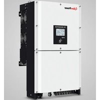
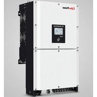
- SOLAR5CONTROLLER5
- TABLE OF CONTENTS
- CHAPTER 1 | SAFETY....3
- 1.1 GENERAL SAFETY ....3
- 1.2 WARNING LABEL....5
- CHAPTER 2 | PRODUCT....7
- CHAPTER 3 | CONTROLLER INSTALLATION....10
- 3.1 INSTALLATION ENVIRONMENT....10
- 3.2 INSTALLATION DIRECTION AND SPACING ....11
- 3.3 KEYPAD AND TERMINAL COVER INSTALLATION....12
- 3.4 WIRING PROTECTION....13
- 3.5 KEYPAD REMOTE USAGE ....14
- CHAPTER 4 | WIRING....17
- 4.1 WIRING SAFETY 17
- 4.2 MAIN CIRCUIT....18
- 4.3 CONTROL CIRCUIT....20
- 4.4 I/O CONNECTIONS....27
- 4.6 WIRING CHECKLIST....31
- CHAPTER 5 | KEYPAD AND PARAMETERS....32
- 5.1 KEYPAD ....32
- 5.2 PARAMETER LIST....37
- CHAPTER 6 | TROUBLESHOOTING....88
- 6.1 ALARM AND FAULT DISPLAYS 88
- CHAPTER 1 | SAFETY
- 1.1 GENERAL SAFETY
- 1.1.1 USAGE
- 1.1.2 RECEIVING
- 1.1.3 INSTALLATION
- 1.1.4 WIRING
- 1.1.5 OPERATION
- 1.1.6 MAINTENANCE
- 1.2 WARNING LABEL
- CHAPTER 2 | PRODUCT
- 2.1 PRODUCT PART
- 2.2 RECEIVING CHECKLIST
- 2.3 PRODUCT DIMENSIONS
- CHAPTER 3 | CONTROLLER INSTALLATION
- 3.1 INSTALLATION ENVIRONMENT
- 3.2 INSTALLATION DIRECTION AND SPACING
- 3.2.1 DIRECTION
- 3.2.2 SPACING
- 3.2.3 SIDE-BY-SIDE INSTALLATION
- 3.3 KEYPAD AND TERMINAL COVER INSTALLATION
- 3.4 WIRING PROTECTION
- 3.4.1 CONTROLLER AND INPUT CABLE
- 3.4.2 OUTPUT CABLE PROTECTION FOR SHORT-CIRCUIT SITUATIONS
- 3.5 KEYPAD REMOTE USAGE
- 3.5.1 REMOTE OPERATION
- 3.5.1.1 REMOTE OPERATION
- 3.5.2.2 PANEL CUT-OUT DIMENSIONS
- CHAPTER 4 | WIRING
- 4.1 WIRING SAFETY
- 4.2 MAIN CIRCUIT
- 4.2.1 MAIN CIRCUIT TERMINAL
- 4.2.2 MAIN CIRCUIT WIRING
- 4.2.2.1 PV INPUT TERMINAL
- 4.2.2.2 POWER OUTPUT TERMINAL
- 4.2.2.4 GROUND TERMINAL
- 4.2.2.5 JUMPER
- 4.2.3 MAIN CIRCUIT CABLE SIZE AND TIGHTENING TORQUE
- 4.3 CONTROL CIRCUIT
- 4.3.1 CONTROL CIRCUIT TERMINALS
- 4.3.1.1 INPUT TERMINALS
- 4.3.1.2 OUTPUT TERMINALS
- 4.3.2 CONTROL CIRCUIT WIRING
- 4.3.2.1 DIGI INPUT CONNECTION FOR PLC
- 4.3.2.2 DIGI INPUT CONNECTION FOR WATER TOWER AND/OR WELL
- 4.3.3 CONTROL CIRCUIT CABLE SIZE AND TIGHTENING TORQUE
- 4.3.4 FERRULE-TYPE TERMINALS
- 4.4 I/O CONNECTIONS
- 4.4.1 NPN AND PNP MODE SELECTION
- 4.4.2 TERMINAL A2 VOLTAGE/CURRENT INPUT SELECTION
- 4.4.3 TERMINAL AM VOLTAGE/CURRENT OUTPUT SELECTION
- 4.4.4 RS-485 COMMUNICATION TERMINATION ON / OFF SWITCH
- 4.6 WIRING CHECKLIST
- CHAPTER 5 | KEYPAD AND PARAMETERS
- 5.1 KEYPAD
- 5.1.1 KEYS AND DISPLAYS
- 5.1.2 KEYPAD DISPLAY
- 5.1.2.1 LED DISPLAY
- 5.1.2.2 LED INDICATION
- 5.1.3 KEYPAD PROGRAMMING
- 5.2 PARAMETER LIST
- 5.2.1 PARAMETERS SETTING FOR SOLAR CONTROLLER
- 5.2.2 PARAMETERS SETTING FOR THE OTHER APPLICATIONS
- CHAPTER 6 | TROUBLESHOOTING
- 6.1 ALARM AND FAULT DISPLAYS
Brand : CyberPower
Model : CPSPI3700EVF380
Category : Solar panel