
FF 120T - Loudspeaker Extron - Free user manual and instructions
Find the device manual for free FF 120T Extron in PDF.


| Product Type | Passive Loudspeaker |
| Model | FF 120T |
| Brand | Extron |
| Speaker Configuration | 2-Way |
| Woofer Size | 12 inches (304.8 mm) |
| Tweeter Size | 1 inch (25.4 mm) soft dome |
| Power Handling (RMS) | 120 W |
| Power Handling (Peak) | 240 W |
| Impedance | 8 ohms |
| Frequency Response | 70 Hz - 20 kHz |
| Sensitivity | 90 dB (1W/1m) |
| Dimensions (H x W x D) | 18.5 x 14.0 x 11.0 inches (470 x 356 x 279 mm) |
| Weight | 15.4 lbs (7.0 kg) |
| Enclosure Material | Medium-density fiberboard (MDF) with black textured finish |
| Mounting | Surface mount with included bracket |
| Input Connectors | Two Speakon-compatible or barrier strip (user selectable) |
| Grille | Perforated steel grille with cloth backing |
| Compliance | CE, FCC Class B, RoHS |
| Protection Features | Over-current, thermal, and RF protection |
| Operating Temperature | 32°F to 104°F (0°C to 40°C) |
| Humidity Range | 10% to 90% non-condensing |
| Included Accessories | Mounting bracket, rubber feet, user manual |
Frequently Asked Questions - FF 120T Extron
User questions about FF 120T Extron
0 question about this device. Answer the ones you know or ask your own.
Ask a new question about this device
Download the instructions for your Loudspeaker in PDF format for free! Find your manual FF 120T - Extron and take your electronic device back in hand. On this page are published all the documents necessary for the use of your device. FF 120T by Extron.
USER MANUAL FF 120T Extron
This setup guide contains installation information about the Extron FF 120T Flat Field® speaker. This speaker is designed for use in plenum rated ceiling spaces and can be dropped into a standard 2 feet by 2 feet or 2 feet by 4 feet (with supplied cross bars) false ceiling tile space on a T-bar grid.
WARNING: May result in serious injury. Installation and service must be performed by authorized personnel only.
Factors to Consider Before Installation
- All wiring and electrical connections must conform to all applicable building codes and local ordinances.
- Installation in a plenum-rated environment requires plenum rated cable or conduit.
Wire Gauge Table
| Number of Wires per Connection Point | Maximum Wire Gauge | |
| 8Ω Configuration | 1 | 12 AWG |
| 2 | 14 AWG | |
| 70 V/100 V Configuration | 1 | 14 AWG |
| 2 | 16 AWG |
- If using secondary support cables, the installer provides the cables.
Installation
- Disconnect power — Power down all attached devices before proceeding.
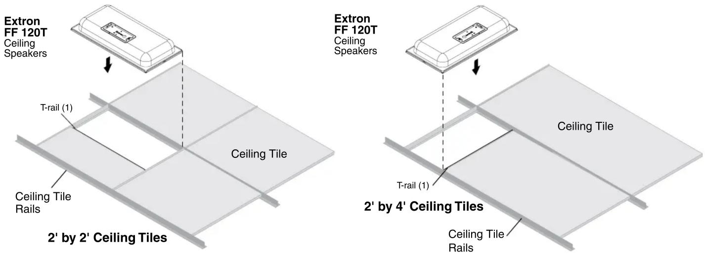
- Remove and cut ceiling tile — Remove the ceiling tile where the FF 120T will be installed. Cut out a 12-inch section from either end of the tile where the speaker will be installed, as shown below.
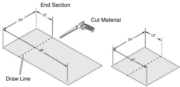
24" x 48" Ceiling Tile 24" x 24" Ceiling Tile
- Install the T-rail — Install the T-rail crosspiece into the ceiling opening up against the cut tile.
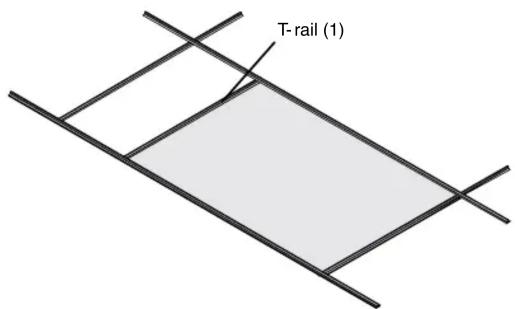
-
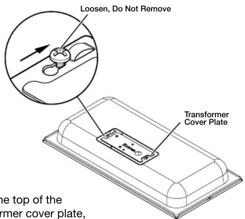
Transformer cover plate — Loosen, but do not remove, the two screws on the top of the transformer cover plate, as shown at right. Next, slide and remove the transformer cover plate, which is installed with the transformer side down.
-
Using Flexible Conduit — When using flexible conduit, insert the conduit into the cover plate opening using an appropriate conduit adapter, and secure the conduit to the plate as shown below.
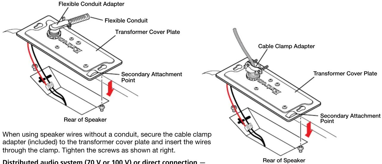
-
Distributed audio system (70 V or 100 V) or direct connection —
-
if wiring a 100 V or 70 V distributed system and using the transformer, proceed to step 7.
-
if bypassing the transformer and wiring directly from the amplifier, proceed to step 9.
-
Connect cables from the amplifier to the transformer on the FF 120T transformer cover plate.
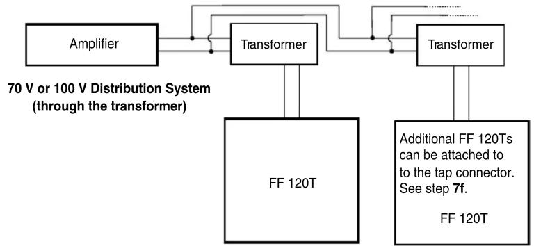
flowchart
graph TD
    A["Amplifier"] --> B["Transformer"]
    B --> C["Transformer"]
    D["FF 120T"] --> B
    E["Additional FF 120Ts can be attached to to the tap connector. See step 7f. FF 120T"] --> C
    style A fill:#f9f,stroke:#333
    style B fill:#ccf,stroke:#333
    style C fill:#cfc,stroke:#333
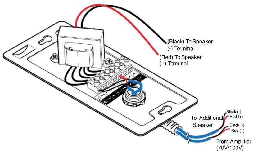
a. Pull the wires from the amplifier through and out of the conduit, if a conduit is used.
b. Route the two wires from the amplifier through the cover plate hole to the transformer side. See the wire gauge table on page 1.
c. Strip 3/16" (5 mm) from the wire ends and keep the wire end strands together by twisting them. Do not tin the wires.
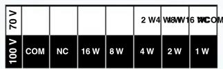
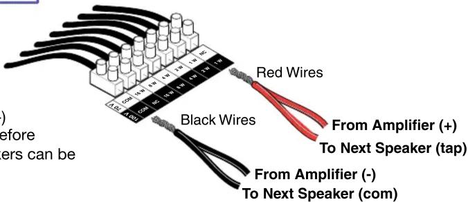
d. Secure the wires to the appropriate taps on the captive screw connectors of the 7-connector terminal block (on the transformer side of the cover plate) as indicated on the tap label (see the note below). The black negative (-) wire attaches to the "COM" terminal, and the red positive (+) wire attaches to the desired terminal tap (see the diagram at right).
NOTE: Observe the 70 V or 100 V system designation as indicated on the tap label.
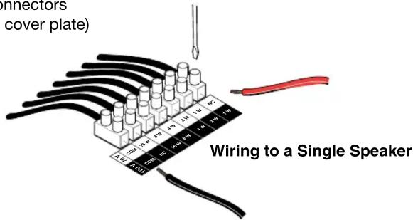
e. Use a small flat blade screwdriver to tighten the terminal block screws.
f. To wire additional speakers, route speaker wires from the second speaker through the cover plate hole to the transformer side. Twist the black negative (-) wires together and the red positive (+) wires together before inserting them into the terminal block. Additional speakers can be daisy-chained this way, as shown at right.
- Connect wires from the transformer to the speaker.
a. Keep the wire strands together by twisting them (do not tin the wires).
b. Connect the red positive (+) wire to the + speaker terminal and connect the black negative (-) wire to the - speaker terminal as shown in step 9b below.
c. Proceed to step 10.
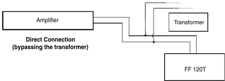
- See the following block diagram.
a. Route the wires from the amplifier to the speaker using the same procedure for routing speaker wire (and conduit if applicable) through the transformer cover plate as described in steps 4 through 7b (see the wire gauge table on page 1). Strip 3/16 inch (5 mm) from the ends of the two speaker wire leads (+ and -) coming from the amplifier. Keep the wire strands together by twisting them (do not tin the wires), and secure the wires to the input terminals of the speaker while observing the correct polarity.
flowchart
graph TD
    A["Amplifier"] --> B["Direct Connection (bypassing the transformer)"]
    B --> C["Transformer"]
    C --> D["FF 120T"]
b. Connect the red positive (+) wire to the + speaker terminal and connect the black negative (-) wire to the - speaker terminal, depending on whether one or two speakers are being connected, as shown below.
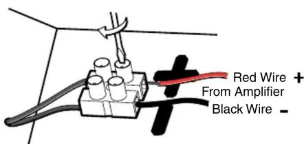
One Speaker
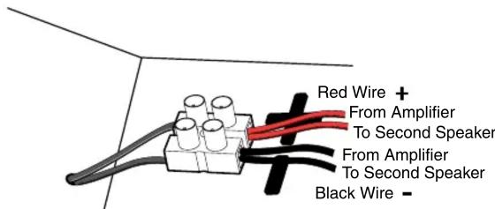
Two Speakers
-
Replace the transformer cover plate and tighten the two cover plate screws that were loosened in step 4.
-
Set the speaker on top of a T-rail making sure to hide the edges behind the grid rail.
- If secondary support cables are being used, install them (see the illustration below).
ATTENTION: DO NOT allow any slack in these support cables.
NOTE: Observe all applicable building codes and local ordinances when installing the speaker.
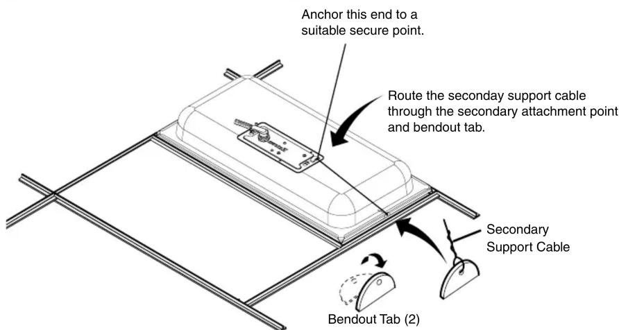
ATTENTION: Repeated bending of the tab may cause it to break off.
a. Temporarily remove a ceiling tile adjacent to the speaker and set it aside.
b. Connect a secondary support cable through the secondary attachment point, and attach it to one of the bendout tabs located on either side of the speaker.
c. Attach the other end of the cable to a sturdy part of the building (studs, roof struts, and so on).
d. For additional secondary support cables repeat as needed (see the FF 120T User Guide for further details).
e. Replace the ceiling tile removed in step 12a.
- Check all wiring before powering up the amplifier.
| Extron Headquarters+1.800.633.9876 (Inside USA/Canada Only)Extron USA - West Extron USA - East+1.714.491.1500 +1.919.850.1000+1.714.491.1517 FAX +1.919.850.1001 FAX | Extron Europe+800.3987.6673(Inside Europe Only)+31.33.453.4040+31.33.453.4050 FAX | Extron Asia+800.7339.8766(Inside Asia Only)+65.6383.4400+65.6383.4664 FAX | Extron Japan+81.3.3511.7655+81.3.3511.7656 FAX | Extron China+4000.398766Inside China Only+86.21.3760.1568+86.21.3760.1566 FAX | Extron Middle East+971.4.2991800+971.4.2991880 FAX | Extron Korea+82.2.3444.1571+82.2.3444.1575 FAX | Extron India1800.3070.3777Inside India Only+91.80.3055.3777+91.80.3055.3737 FAX |
Brand : Extron
Model : FF 120T
Category : Loudspeaker