
ShareLink Pro 2000 - Wireless Content Sharing Extron - Free user manual and instructions
Find the device manual for free ShareLink Pro 2000 Extron in PDF.


| Product Type | 4K Wireless Presentation System |
| Brand | Extron |
| Model | ShareLink Pro 2000 |
| Dimensions | 1 inch (2.5 cm) high, half-rack width metal enclosure |
| Weight | Approximately 2.5 lb (1.1 kg) |
| Power Supply | 12 V DC, 3.0 A max, or PoE+ (Power over Ethernet) |
| HDMI Input | 1x HDMI 2.0 (up to 4K @ 30 Hz in window mode, 4K @ 60 Hz in pass-through) |
| HDMI Output | 1x HDMI 2.0 with CEC (up to 4K @ 60 Hz, 4:4:4, 8-bit) |
| Audio Input/Output | Line-level stereo via captive screw connectors |
| Supported Clients | Windows, macOS, iOS, Android via app or browser (WebShare) |
| Simultaneous Presenters | Up to 4 sources including HDMI input |
| Wireless Standards | 802.11 a/b/g/n/ac (via external WAP or Miracast adapter) |
| Miracast Support | Optional WFA 100 adapter for Windows 10 devices |
| Screen Mirroring | Native AirPlay for iOS/macOS, Miracast for Windows |
| Moderator Mode | Allows moderator to approve/control content |
| Encryption | 128-bit data encryption for secure transmission |
| Front Panel | USB-C config port, HDMI mode buttons, status LEDs |
| Rear Panel | HDMI in/out, audio in/out, LAN (PoE+), reset button |
| Management | PCS (Product Configuration Software), embedded web page, SIS commands |
| Operating Temperature | 32 to 122 °F (0 to 50 °C) |
| Care and Cleaning | Wipe with a dry, lint-free cloth. Do not use liquid cleaners. |
| Safety Compliance | FCC Class A, CE, UL listed (refer to manual) |
Frequently Asked Questions - ShareLink Pro 2000 Extron
User questions about ShareLink Pro 2000 Extron
0 question about this device. Answer the ones you know or ask your own.
Ask a new question about this device
Download the instructions for your Wireless Content Sharing in PDF format for free! Find your manual ShareLink Pro 2000 - Extron and take your electronic device back in hand. On this page are published all the documents necessary for the use of your device. ShareLink Pro 2000 by Extron.
USER MANUAL ShareLink Pro 2000 Extron
4K Wireless Presentation System
User Guide
Collaboration Systems
68-3820-01, Rev. A
08 24
Safety Instructions
Safety Instructions • English

WARNING: This symbol, when used on the product, is intended to alert the user of the presence of uninsulated dangerous voltage within the product's enclosure that may present a risk of electric shock.
ATTENTION: This symbol, ⚠, when used on the product, is intended to alert the user of important operating and maintenance (servicing) instructions in the literature provided with the equipment.
For information on safety guidelines, regulatory compliances, EMI/EMF compatibility, accessibility, and related topics, see the Extron Safety and Regulatory Compliance Guide, part number 68-290-01, on the Extron website, www.extron.com.
All trademarks mentioned in this guide are the properties of their respective owners. The following registered trademarks ( ^® ), registered service marks ( ^SM ), and trademarks ( ^TM ) are the property of RGB Systems, Inc. or Extron (see the current list of trademarks on the Terms of Use page at www.extron.com):
| Registered Trademarks (®) |
| Extron, Cable Cubby, ControlScript, CrossPoint, DTP, eBUS, EDID Manager, EDID Minder, eLink, Everlast, Flat Field, FlexOS, Glitch Free, Global Configurator, Global Scripter, GlobalViewer, Hideaway, HyperLane, IP Intercom, IP Link, Key Minder, LinkLicense, LockIt, MediaLink, MediaPort, NAV, NetPA, PlenumVault, PoleVault, PowerCage, PURE3, Quantum, ShareLink, Show Me, SoundField, SpeedMount, SpeedSwitch, StudioStation, System INTEGRATOR, TeamWork, TouchLink, V-Lock, VideoLounge, VN-Matrix, VoiceLift, WallVault, WindoWall, XPA, XTP, XTP Systems, and ZipClip |
| Registered Service Mark ^(SM) : S3 Service Support Solutions |
| Trademarks ^(TM) |
| AAP, AFL (Accu-RATE Frame Lock), ADSP (Advanced Digital Sync Processing), AVEdge, CableCover, CDRS (Class D Ripple Suppression), Codec Connect, DDSP (Digital Display Sync Processing), DMI (Dynamic Motion Interpolation), Driver Configurator, DSP Configurator, DSVP (Digital Sync Validation Processing), EQIP, FastBite, Flex55, FOX, FOXBOX, InstaWake, IP Intercom HelpDesk, MAAP, MicroDigital, Opti-Torque, PendantConnect, ProDSP, QS-FPC (QuickSwitch Front Panel Controller), Room Agent, Scope-Trigger, SIS, Simple Instruction Set, Skew-Free, SpeedNav, Triple-Action Switching, True4K, True8K, Vector ^TM 4K, WebShare, XTRA, and ZipCaddy |
FCC Class A Notice
This equipment has been tested and found to comply with the limits for a Class A digital device, pursuant to part 15 of the FCC rules. The Class A limits provide reasonable protection against harmful interference when the equipment is operated in a commercial environment. This equipment generates, uses, and can radiate radio frequency energy and, if not installed and used in accordance with the instruction manual, may cause harmful interference to radio communications. Operation of this equipment in a residential area is likely to cause interference. This interference must be corrected at the expense of the user.
ATTENTION:
- This unit was tested with shielded I/O cables on the peripheral devices. Shielded cables must be used to ensure compliance with FCC emissions limits.
- For more information on safety guidelines, regulatory compliances, EMI/EMF compatibility, accessibility, and related topics, see the Extron Safety and Regulatory Compliance Guide on the Extron website.
Battery Notice
This product contains a battery. Do not open the unit to replace the battery. If the battery needs replacing, return the entire unit to Extron (for the correct address, see the Extron Warranty section on the last page of this guide).
CAUTION: Risk of explosion. Do not replace the battery with an incorrect type. Dispose of used batteries according to the instructions.
Conventions Used in this Guide
Notifications
The following notifications are used in this guide:
ATTENTION:
- Risk of property damage.
- Risque de dommages matériels.
NOTE: A note draws attention to important information.
Specifications Availability
Product specifications are available on the Extron website, www.extron.com.
Contents
Introduction......1
About the ShareLink Pro 2000 ....1
Features 2
Installation....4
Rear Panel Features and Cabling 4
Power Notifications 5
HDMI Connection....6
Reset Modes 7
Front Panel Features and Cabling....9
Using the Standby Screen....10
Operation Using a Computer....11
Connecting a Computer to the ShareLink Pro 2000....11
Connecting through an External WAP....11
Connecting through a Network Hub, Switch, or Router 11
Downloading the ShareLink Pro 2000 Software....12
Using the ShareLink Pro 2000 Software ....14
Connecting to the ShareLink Pro 14
Presenting Content 15
Moderating a Presentation....16
Using the Embedded Web Page 18
Viewing a Presentation Using WebView 19
Presenting a Desktop Using WebShare....19
Using the Admin Page....21
Mirroring a Screen Using the WFA 100 Miracast Adapter 23
About the WFA 100....23
Using the WFA 100 23
Screen sharing options 25
Disconnecting from the display 25
Operation Using a Mobile Device....26
Downloading the ShareLink Pro App....26
Connecting to a ShareLink Pro Unit....27
Presenting Content 28
App Menu....29
Using iOS Screen Mirroring....30
Discovering a ShareLink Pro Device on a Different Subnet for Apple Screen Mirroring....31
Enterprise Discovery Service.... 33
Enterprise Discovery Service - Overview 33
How EDS Works 34
Selecting and Configuring the EDS Host....36
Configuring the EDS Host in PCS 36
Configuring EDS Clients in PCS....37
Enabling EDS in Client Devices 37
Managing Login Code Settings for EDS Clients 38
Other Configuration Options.... 39
Device Discovery using ShareNext™ 39
Using ShareNext with the ShareLink Pro Software and Mobile App 40
Using ShareNext with Apple Screen Mirroring....40
Digital Signage Feature....41
Miracast Connection Using the WFA 100....43
Miracast Overview....43
Miracast Connection Methods....44
Configuring the WFA 100 Channel....47
Miracast Troubleshooting 48
SIS Configuration and Control....50
Host Device Connection 50
SIS Overview....50
Host and Device Communication....50
Error Responses 50
Command and Response Tables Overview....51
Symbol Definitions 51
Command and Response Tables for SIS Commands 55
Expo and Streaming....70
Bluetooth 76
CEC Commands....76
Reference Information 79
Mounting....79
Tabletop Mounting....79
Furniture Mounting....79
Rack Mounting 79
Firmware Download 80
Firewall Traversal 81
Toolbelt 82
Secure Sockets Layer (SSL) Certificates 83
Troubleshooting 84
Introduction
This section covers the following:
• About the ShareLink Pro 2000
- Features
About the ShareLink Pro 2000
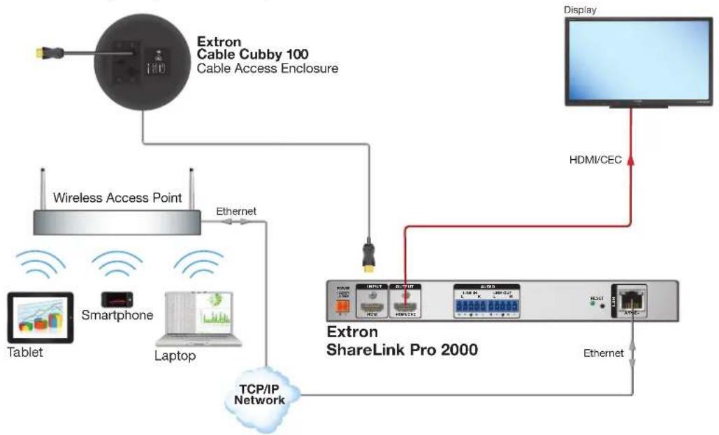
The ShareLink Pro 2000 is a 4K wireless presentation system that enables anyone to present wireless or wired content from their computers, tablets, or smartphones onto a display for easy collaboration.
It features streaming technology that supports simultaneous display of up to four content sources, including an HDMI-connected device. The HDMI input supports wired connections from any connected source in the room. To support a wide range of environments, the ShareLink Pro 2000 has collaboration and moderator modes that facilitate both open and restrictive environments.
The ShareLink Pro 2000 provides easy integration of AV and mobile devices into meeting, huddle, collaboration, and presentation spaces.
flowchart
graph TD
    A["Extron Cable Cubby 100 Cable Access Enclosure"] --> B["Wireless Access Point"]
    B --> C["TCP/IP Network"]
    C --> D["Extron ShareLink Pro 2000"]
    D --> E["Display"]
    D --> F["HDMI/CEC"]
    D --> G["Ethernet"]
    H["Tablet"] --> I["Smartphone"]
    I --> J["Laptop"]
    J --> K["Ethernet"]
    L["Radio"] --> M["Radio"]
    N["Radio"] --> O["Radio"]
    P["Radio"] --> Q["Radio"]
    R["Radio"] --> S["Radio"]
    T["Radio"] --> U["Radio"]
    V["Radio"] --> W["Radio"]
    X["Radio"] --> Y["Radio"]
    Z["Radio"] --> AA["Radio"]
    AB["Radio"] --> AC["Radio"]
    AD["Radio"] --> AE["Radio"]
    AF["Radio"] --> AG["Radio"]
    AH["Radio"] --> AI["Radio"]
    AJ["Radio"] --> AK["Radio"]
    AL["Radio"] --> AM["Radio"]
    AN["Radio"] --> AO["Radio"]
    AP["Radio"] --> AQ["Radio"]
    AR["Radio"] --> AS["Radio"]
    AT["Radio"] --> AU["Radio"]
    AV["Radio"] --> AW["Radio"]
    AX["Radio"] --> AY["Radio"]
    AZ["Radio"] --> BA["Radio"]
    BB["Radio"] --> BC["Radio"]
    BD["Radio"] --> BE["Radio"]
    BF["Radio"] --> BG["Radio"]
    BH["Radio"] --> BI["Radio"]
    BJ["Radio"] --> BK["Radio"]
    BL["Radio"] --> BM["Radio"]
    BN["Radio"] --> BO["Radio"]
    BP["Radio"] --> BQ["Radio"]
    BR["Radio"] --> BS["Radio"]
    BT["Radio"] --> BU["Radio"]
    BV["Radio"] --> BW["Radio"]
    BX["Radio"] --> BY["Radio"]
    BZ["Radio"] --> CA["Radio"]
    CB["Radio"] --> CC["Radio"]
    CD["Radio"] --> CE["Radio"]
    CF["Radio"] --> CG["Radio"]
    CH["Radio"] --> CI["Radio"]
    CJ["Radio"] --> CK["Radio"]
    CL["Radio"] --> CM["Radio"]
    CN["Radio"] --> CO["Radio"]
    CP["Radio"] --> CS["Radio"]
    CT["Radio"] --> CU["Radio"]
    CV["Radio"] --> CW["Radio"]
    CX["Radio"] --> CY["Radio"]
    CZ["Radio"] --> DA[" Radio "]
    DB["Radio"] --> DC[" Radio "]
    DD["Radio"] --> DE[" Radio "]
    DF["Radio"] --> DG[" Radio "]
    DH["Radio"] --> DI[" Radio "]
    DJ["Radio"] --> DK[" Radio "]
    DL["Radio"] --> DM[" Radio "]
    DN["Radio"] --> DE
    DO --> DU[DVI/DCI/DCI/DCI/DCI/DCI/DCI/DCI/DCI/DCI/DCI/DCI/DCI/DCI/DCI/DCI/DCI/DCI/DCI/DCI/DCI/DCI/DCI/DCI/DCI/DCI/DCI/DCI/DCI/DCI/DCI/DCI/DCI/DCI/DCI/
      |
Figure 1. ShareLink Pro 2000 Application Diagram
Features
- Provides full screen mirroring for all devices — Display the entire screen of your device through the wireless presentation system for more fluid and easy collaboration sessions.
- ConferenceShare™ enables wireless use of room cameras for UC meetings — Facilitates wireless sharing of content from USB meeting room devices, such as cameras or microphones, for use in Microsoft Teams, Zoom, or other UC meetings.
- WebShare™ shares content via a web browser — Enables content sharing via a standard web browser, without the need to download software. This is ideal for users who want to share content quickly without installing anything on their computer. Works with Chrome™ browser supported on Windows®, macOS, and Chrome operating systems.
- Wirelessly share content from mobile devices — Connects a wide variety of devices to the system wirelessly or through a wired LAN connection.
- Wireless and wired sources can collaborate simultaneously — HDMI input enables wired users or sources to collaborate simultaneously with wireless users in the same session.
- Supports Mac and Windows computers as well as Apple ^® and Android ^TM tablets and smartphones
- Dedicated app provides consistent user experience across platforms — Similar interface for all platforms makes it easy for users to assist one another or move between devices regardless of how they connect and share content.
- View up to four pieces of content simultaneously from any connected user — Fosters collaboration and discussion by comparing multiple sources concurrently and reduces or eliminates the need to switch between sources for more effective collaboration.
- HDMI output supports computer and video resolutions up to 4K — Resolutions up to 4096x2160 with 4:4:4 chroma subsampling at 8 bits of color.
- HDCP compliant — Ensures display of content-protected media on HDMI input and output for interoperability with other HDCP-compliant devices.
- EDID Minder automatically manages EDID communication between HDMI connected devices — EDID Minder ensures that all sources power up properly and reliably output content for display.
- Collaboration mode allows any attendee to display content and control the presentation — Enables content display from any connected device to enhance interactivity in brainstorming sessions, team meetings, and other collaborative environments.
- Moderator mode ensures only approved user content is displayed — Enables the moderator to select which users can access the display and how the content is displayed.
- Display codes ensure content is delivered only to the selected display devices — Randomly generated or user-defined display authentication codes prevent unintentional sharing or display of content to an adjacent space.
- WebShare technology displays slide images on attendee's personal devices via a web browser — The ShareLink Pro 2000 enables meeting content to display on a participant mobile device. This is ideal for attendees who cannot easily view the main display.
- 128-bit data encryption — A variety of security protocols ensure that all content transmitted between devices and the ShareLink Pro 2000 is fully encrypted and secure.
- Power over Ethernet (PoE+) allows the ShareLink Pro to receive power and communication over a single Ethernet cable, eliminating the need for a local power supply.
-
Fully customizable welcome screen — Multiple configuration options to show, hide, or customize information on the welcome screen, so users can quickly connect and begin sharing their content.
-
Connects to an existing wireless network — Leverages an existing wireless network infrastructure for the connection of mobile devices.
- Includes user-friendly software for screen mirroring, sharing, and advanced control — Provides both an executable that does not require administrator access rights and a version that can be deployed by IT administrators.
- Video screen saver — The ShareLink Pro 2000 can be set to automatically mute video and sync output to the display device when no active connections are detected, automatically entering the display into standby mode to conserve energy, reducing costs and promoting panel life.
- Front panel security lockout — Prevents unauthorized use in non-secure environments. Set via Extron PCS software.
- Easy setup and commissioning with Extron PCS – Product Configuration Software — Conveniently configure multiple products using a single software application.
- Display control options including CEC over HDMI connection
- Automatic input cable equalization to 50 feet (15 meters) — Actively conditions incoming HDMI signals to compensate for signal loss when using long HDMI cables, low quality HDMI cables, and source devices with poor HDMI signal output
- Compatible with Extron mounting solutions — Easy mounting with Extron low-profile and under-desk mounts, under-table kits, and rack-shelf options.
- 1" (2.5 cm) high, half rack width metal enclosure — Compact, low profile enclosure allows discreet installation within a lectern or behind a flat panel display.
- Extron Pro Series Secure Control — The ShareLink Pro 2000 is designed to work natively with Extron Pro Series control systems via dedicated Secure Platform Interface that provides encrypted communication at all times between an Extron Pro Series control processor and the ShareLink Pro 2000 4K wireless presentation system.
This section covers the following:
• Rear Panel Features and Cabling
• Front Panel Features and Cabling
• Using the Standby Screen
Rear Panel Features and Cabling
The following section covers rear panel features and cabling procedures. If mounting is necessary before connecting cables, see Mounting on page 79.

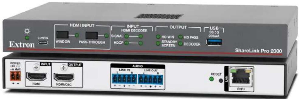
Figure 2. Rear Panel
Power input — Connect the power supply (sold separately) to this two-pole captive screw connector (see the Power Notifications on the next page for important information).
NOTES:
- Alternatively, the PoE+ port can be used to power the ShareLink Pro via a Power over Ethernet (PoE+) source device.
- If both power options are connected (12 V power supply and PoE+), 12 VDC has precedence.
B HDMI input — Connect an HDMI source device to this input.
NOTE: For HDMI connections (B and C), use an Extron LockIt Cable Lacing Bracket to secure the HDMI connector to the device (see HDMI Connection on page 6).
© HDMI output — Connect an HDMI display device to this female HDMI connector.
D Audio input — Connect a balanced or unbalanced stereo (or dual mono) line level audio source to this 5-pole 3.5 mm captive screw connector. Wire the connector as shown in figure 2:
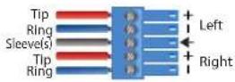
Balanced Audio Input
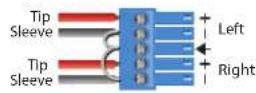
Unbalanced Audio Input
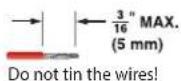
Figure 3. Audio Input Captive Screw Connector Wiring
Audio output — Connect a balanced or unbalanced stereo (or dual mono) line level audio device to this 5-pole 3.5 mm captive screw connector. Wire the connector as shown below.
ATTENTION:
- For unbalanced audio, connect the sleeves to the ground contact. DO NOT connect the sleeves to the negative (−) contacts.
- Pour l'audio asymétrique, connectez les manchons au contact au sol. Ne PAS connecter les manchons aux contacts négatifs (-).
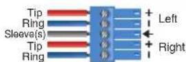
Balanced Audio Output Unbalanced Audio Output
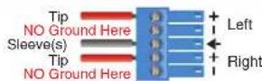
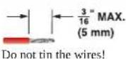
Figure 4. Audio Output Captive Screw Connector Wiring
ShareLink Pro 2000 • Installation 4
F Reset button and LED — Use this button to reset the device (see Reset Modes on page 7 for details on the various resets and LED states).
G LAN port — Use an Ethernet cable to connect a network switch, hub, router, or PC to this RJ-45 port. This port can also be used for Power over Ethernet (PoE+).
NOTE:
Default IP settings:
• IP address: 192.168.254.254
• DNS address: 0.0.0.0
• Gateway IP address: 0.0.0.0
- DHCP: Off
- Subnet mask: 255.255.255.0
- Link speed and duplex level: autodetected
LED indicators:
- Left LED (amber) indicates link speed: 1 blink per second: 10 Mbps, 2 blinks per second: 100 Mbps, 3 blinks per second: 1 Gpbs
- Right LED (green) indicates a link is active.
Power Notifications
ATTENTION:
To secure the HDMI cable to the HDMI input connector, use an Extron LockIt Cable Lacing Bracket and a tie wrap.
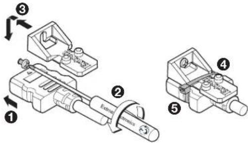
Figure 5. Installing the Locklt Cable Lacing Bracket
- Plug the HDMI cable into the panel connection (see figure 5, ①).
- Loosen the HDMI connection mounting screw from the panel (②) enough to allow the LockIt to be placed over it. The screw does not have to be removed.
- Place the LockIt on the screw and against the HDMI connector (③), and then tighten the screw to secure the bracket.
- Loosely place the included tie wrap around the HDMI connector and the LockIt (④).
- While holding the connector securely against the cable lacing bracket, use pliers or similar tools to tighten the tie wrap, then remove any excess length (⑤).
ATTENTION:
The rear panel Reset button can activate four different reset modes (see the table below for a summary of each reset mode and LED state).
NOTE: Review the reset modes carefully. Some reset modes delete all user-loaded content.
| Reset Mode Summary | ||
| Mode Activation Result | ||
| Use Factory FirmwareResets the firmware to the factory version temporarily if an incompatibility issue arises with the current firmware. | Hold down the recessed Reset button while applying power to the device.NOTE: After this reset, update the device with the latest firmware version. Do not operate the device with the firmware version that results from this reset. | The device reverts to the factory default firmware for a single power cycle. All user files and settings are maintained.NOTE: If this reset was made by mistake or is no longer desired, cycle power to the device again to restore the firmware version running prior to the reset. |
| Reset to Factory DefaultsResets all device settings to default values but retains user-loaded files and IP settings.NOTE: This reset is the equivalent of SIS command ZXXX (see page 68). | Hold down the Reset button (for about 3 seconds) until the Reset LED blinks once. Then, press the Reset button again momentarily (<1 sec-ond). | The device reverts all settings to the default values except:IP related settingsUser-loaded files and configurationsNOTE:This mode does not affect passwords.The Reset LED blinks four times in quick succession during the reset, then remains on. |
| Reset Network SettingsResets the IP settings back to factory defaults. | Hold down the Reset button for about 6 seconds until the Reset LED blinks twice (once at 3 seconds, then twice at 6 seconds). Then, within one second, press the Reset button again momentarily (for <1 second).NOTE: Nothing happens if the button is not pressed within one second. | The device reverts IP settings to the default values.ARP capability is enabled.IP address, subnet mask, gateway address, and port mapping reset to the default value.DHCP is disabled.Events are disabled.NOTE: The Reset LED blinks four times in quick succession during the reset, then remains on. |
| Mode Activation Result | ||
| Full Factory ResetResets the device to default configuration.NOTE: This reset is the equivalent of SIS command ZQQQ (see page 68). | Hold down the Reset button for about 9 seconds until the Reset LED blinks three times (once at 3 seconds, twice at 6 seconds, and thrice at 9 seconds). Then, within one second, press the Reset button again momentarily (for <1 second).NOTE: Nothing happens if the button is not pressed within one second. | The device reverts user settings to the factory default values (firmware excluded).All user modifiable configuration is reset to default values, including IP settings and real-time adjustments.All user loaded files are deleted.NOTE:Admin password resets to extron.The Reset LED blinks four times in quick succession during the reset, then remains on. |
| Toggle DHCP Client | To enable or disable the DHCP client for the LAN port:1. Press the Reset button five times (consecutively).2. Release the button. Do not press the button within 3 seconds following the fifth press. | The Reset LED blinks 6 times if the DHCP client is enabled.The Reset LED blinks 3 times if the DHCP client is disabled. |
| NOTES:By default, DHCP is off for the LAN port and the unit uses a static IP address.If DHCP has been enabled, when you disable DHCP, the unit reverts to using the previously-set static IP address. | ||
Front Panel Features and Cabling

flowchart
graph LR
    A["Extron"] --> B["CONFIG"]
    B --> C["WINDOW"]
    C --> D["PASS-THROUGH"]
    D --> E["HDMI INPUT"]
    E --> F["SIGNAL"]
    F --> G["HDCP"]
    G --> H["INPUT"]
    H --> I["HDMI DECODER"]
    I --> J["OUTPUT"]
    J --> K["HD WIN HD PASS"]
    K --> L["STANDBY SCREEN"]
    L --> M["DECODER"]
    M --> N["USB SS BG 900mA"]
    style A fill:#f9f,stroke:#333
    style B fill:#ccf,stroke:#333
    style C fill:#cfc,stroke:#333
    style D fill:#fcc,stroke:#333
    style E fill:#cff,stroke:#333
    style F fill:#ffc,stroke:#333
    style G fill:#cfc,stroke:#333
    style H fill:#fcc,stroke:#333
    style I fill:#cfc,stroke:#333
    style J fill:#cfc,stroke:#333
    style K fill:#cfc,stroke:#333
    style L fill:#cfc,stroke:#333
    style M fill:#cfc,stroke:#333
    style N fill:#fcc,stroke:#333
Figure 6. Front Panel
Power LED indicator — Lights green when the unit is powered on.
B Configuration port — Connect a PC to this front panel USB-C connector to configure the ShareLink Pro. The port uses IP over USB technology. The IP address is always 203.0.113.22 and CANNOT be changed. This port is also discoverable via Extron Toolbelt and Extron PCS software.
© HDMI input selection buttons — Use these buttons to select between HDMI window mode and pass-through mode. These modes determine how the HDMI input is presented on the output (see below for details).
NOTE: Selection of one mode deselects the other mode.
- HDMI Window button – Activates HDMI window mode, which displays the HDMI input source in addition to or alongside any content currently being shared by client devices.
NOTE: Maximum input resolution for this mode is 4K @ 30 Hz.
- HDMI Pass-Through button – Activates HDMI pass-through mode, which routes the HDMI input signal directly to the HDMI output unaltered. In this mode, neither the status bar nor decoder input streams are shown on the output.
NOTE: Maximum output resolution for this mode is 4K @ 60 Hz.
D Input LED indicators:
- HDMI Signal LED – Lights green when an HDMI signal is detected.
- Decoder Signal LED – Lights green when one stream is detected. Flashes green when more than one stream is detected at the same time.
- HDMI HDCP LED – Lights green when the HDMI input signal is encrypted. Turns off when the HDMI input signal is not encrypted or when HDCP authorization is disabled.
- Decoder HDCP LED – Lights green when the decoder source signal is encrypted. Turns off when the decoder source signal is not encrypted or when HDCP authorization is disabled.
E Output LED indicators — These LEDs light green when the source signals are present and active on the output.
- HD Win – Lights green when the HDMI source is active on the output in HDMI window mode. Lights amber if HDMI pass-through mode is activated after originally being in window mode.
- Decoder – Lights green when at least one stream is active on the output. Lights amber if HDMI pass-through mode is activated after at least one stream was active on the output.
- Standby Screen – Lights green when the standby screen is active on the output. Lights amber if HDMI pass-through mode is activated while the ShareLink Pro output displays the standby screen.
NOTE: The standby screen images are displayed only when HDMI and decoder sources are not active.
- HD Pass – Lights green when the HDMI source is active on the output in pass-through mode.
USB port – Connect the Extron WFA 100 Wi-Fi Miracast adapter to this port. This adapter enables anyone to share content from a Windows 10 device without installing any software (see Mirroring a Screen Using the WFA 100 Miracast Adapter on page 23). This port can also be used for USB peripherals when using ConferenceShare (see the ConferenceShare User Guide at www.extron.com).
Using the Standby Screen
Once the ShareLink Pro 2000 is connected and powered on, the standby screen appears on the display:
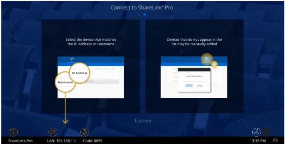
Figure 7. Standby Screen
① Hostname — Use this hostname to identify and access the ShareLink Pro 2000 during connection.
② IP address — Use this IP address to identify and access the ShareLink Pro 2000 during connection and to download the ShareLink Pro client software.
③ Login code — Use this code to connect to the ShareLink Pro 2000 using the software. This code can be customized or disabled via the Product Configuration Software (PCS).
④ Time — The time format can be adjusted via PCS.
NOTE:
- The standby screen background can be changed using PCS. For best results, make sure the desired background image matches the display output resolution.
- The status bar at the bottom of the standby screen (showing the IP addresses, hostname, and login code) is overlaid over the background image. Ensure that this portion of the background image does not contain important information as it will be covered by the status bar.
- The status bar color can also be changed using PCS.
Operation Using a Computer
Users can present from a Windows or Mac computer using the ShareLink Pro 2000 software. This section covers the following:
- Connecting a Computer to the ShareLink Pro 2000
• Downloading the ShareLink Pro 2000 Software
• Using the ShareLink Pro 2000 Software
• Using the Embedded Web Page
• Mirroring a Screen Using the WFA 100 Miracast Adapter
Connecting a Computer to the ShareLink Pro 2000
There are two ways to connect a computer to the ShareLink Pro 2000:
- Wirelessly, through an external wireless access point (WAP)
- Wired, through a network device
See the following instructions for your preferred connection method.
Connecting through an External WAP
- Ensure that the external WAP and the ShareLink Pro 2000 are wired to the same network.
- Ensure that the ShareLink Pro 2000 is powered on and that wireless network capability is enabled on your computer.
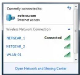
- Open the wireless networks on your PC and connect to the external WAP.
Connecting through a Network Hub, Switch, or Router
- Ensure that your computer is connected to the network through a hub, switch, or router.
- Connect the RJ-45 connector of the ShareLink Pro 2000 to the network device using an RJ-45 cable.
Downloading the ShareLink Pro 2000 Software
The ShareLink Pro 2000 software can be downloaded from the embedded web page or from the Extron website. Follow the instructions below for your preferred download method.
NOTES:
- For other details on the embedded web page, see Using the Embedded Web Page on page 18.
- For instructions on mirroring the computer screen using the optional ShareLink Pro WFA 100 Miracast™ adapter, see Mirroring a Screen Using the WFA 100 Miracast Adapter on page 23.
Downloading the software from the embedded Web pages
- Ensure that your computer is connected to the ShareLink Pro 2000, either through an external WAP or through a physical network connection. The computer and the ShareLink Pro 2000 must be on the same network.
- Open a web browser and enter the ShareLink Pro IP address into the browser.
NOTE: The IP address is shown on the standby screen (see figure 7, ② on page 10).
The ShareLink Pro 2000 landing page opens on the browser:
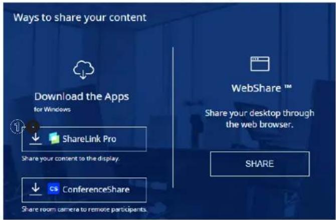
Figure 8. ShareLink Pro Landing Page
- Click the ShareLink Pro button (see figure 8, ①) to start the download.
NOTE: macOS users: The .app software file is embedded in a .zip file. Some browsers automatically extract (unzip) the .app file. However, in some cases, the user may need to extract the file.
Downloading the software from the Extron website
- On the Extron website, go to the Download tab and click Software (see figure 9, ①).
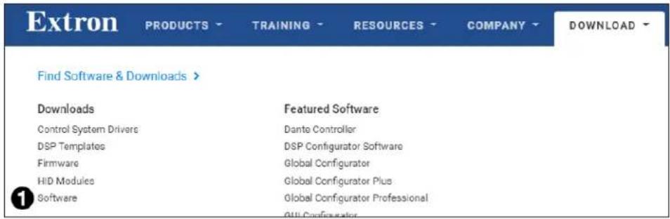
Figure 9. Download Page on the Extron Website
- Search for ShareLink Pro in the Search Software field and select the file for your operating system (see figure 10).
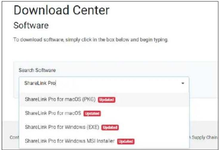
Figure 10. Software Download Link
- Click the Download link on the next page to start the download. Note where the file is saved.
- Open the saved executable (.exe) file.
- Follow the instructions that appear on the screen to install the program.
Using the ShareLink Pro 2000 Software
Connecting to the ShareLink Pro
If the software is not yet connected to the ShareLink Pro device, follow these steps:
-
Open the ShareLink Pro 2000 software. The software searches for available devices on your network and lists them.
-
Click the desired ShareLink Pro 2000 device (see the standby screen for the device name).
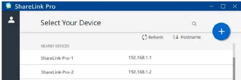
Figure 11. ShareLink Pro Devices List
NOTE:
- The ShareLink Pro software automatically discovers ShareLink Pro units in the same subnet as the client device.
- If your ShareLink Pro unit is not listed, click the refresh button.
-
If the device is still not listed, select the add (●) icon. Enter the hostname or IP address as instructed on the app screen.
-
When prompted, enter the login code and click Connect.
NOTE: The login code is shown on the standby screen (see figure 7 on page 10).
When connection is established, the Share screen appears (see figure 12 on the next page).
Presenting Content
Use the Share screen to present your computer screen on the display device. Select the ● button to see the options below.
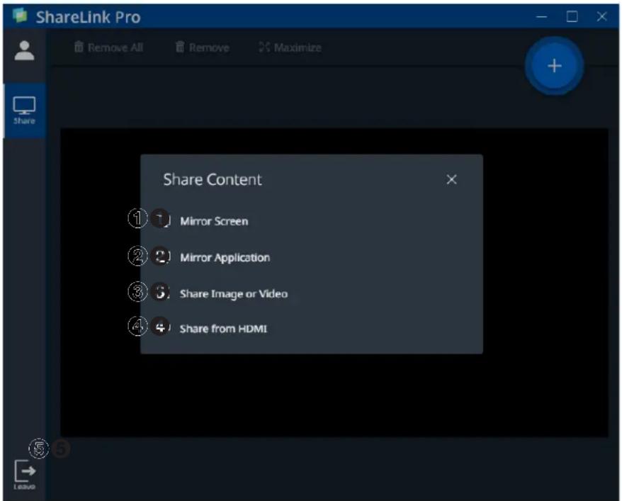
Figure 12. Share Screen
NOTE:
- This Share screen also shows the ongoing presentation.
- Up to four presenters can stream content simultaneously. The ShareLink Pro automatically arranges the incoming presentations side by side on the display.
- A moderator can control the content presented by participants during a session (see Moderating a Presentation on the next page for details).
Select from the following presentation options:
① Mirror Screen — Click this button to automatically mirror your computer screen on the display device.
② Mirror Application — Click this button to open a sub-menu, showing all the programs and applications currently running on your computer. Select a program or application to automatically mirror it on the display.
③ Share Image or Video — Click this button to navigate to a specific video or image file on your computer. Double-click the video or image file to present it on the display.
See the NOTE on the next page for a list of supported file formats.
Share from HDMI — Click this button to share the connected HDMI source as a window.
Leave — Click this button and select Leave Session to exit the presentation session.
NOTE:
The following file formats are supported:
• Image: BMP, JPG, PNG, TIFF
• Video: 264, AVI, M2T, M2TS, M4V, MKV, MOV, MP4, MPG, SDP, TS
The following codecs are supported:
- Video: MPEG-2, MPEG4/XviD (Simple Profile), H.264 (Baseline, Main, High, Stereo SEI Profile), VC1 (Simple, Main, Advanced Profile), WEBM VP8, MJPEG VP8 (Mirror Screen feature only)
- Audio: AAC-LC (MPEG-2 part 7, MPEG-4 part 3, sub part 4 and part 14, MP4 mono or stereo audio, max 384 kbps) PCM mono or stereo 16 kHz to 96 kHz, 16-bit to 32-bit OPUS (Mirror Screen feature only)
Moderating a Presentation
The ShareLink Pro 2000 default collaboration mode ("Run-Time" mode) allows a user to display content as a participant, or to control the presentation as a moderator. In this mode, everyone in the session starts as a participant, but a user may choose to take over as moderator.
A moderator can accept or decline participants, stop shared content, and remove active participants from a session. Follow the instructions below to moderate a presentation.
NOTE: The following instructions apply only when the ShareLink Pro is set to Run-Time mode (the default setting). Run-Time mode can be disabled via PCS, and changed to either of the following modes:
• Full Control - No limitations to controls or sharing
• Moderate - Moderator manages access and sharing
- Click the participant icon (see figure 13, ①), and select Moderator (②) from the menu.
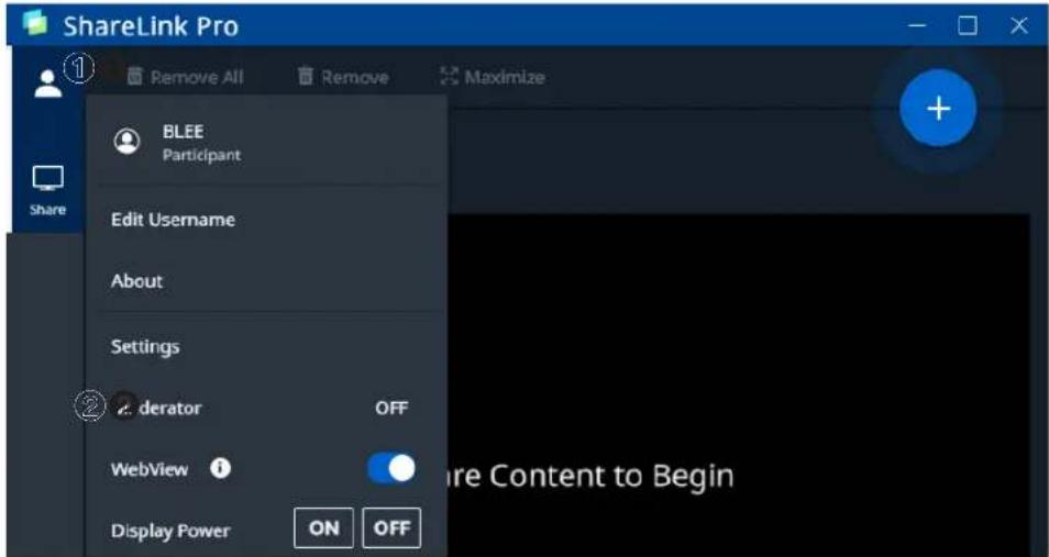
Figure 13. ShareLink Pro Software Menu
- Click Enable Moderator. The Moderate page appears on the software menu as shown below:
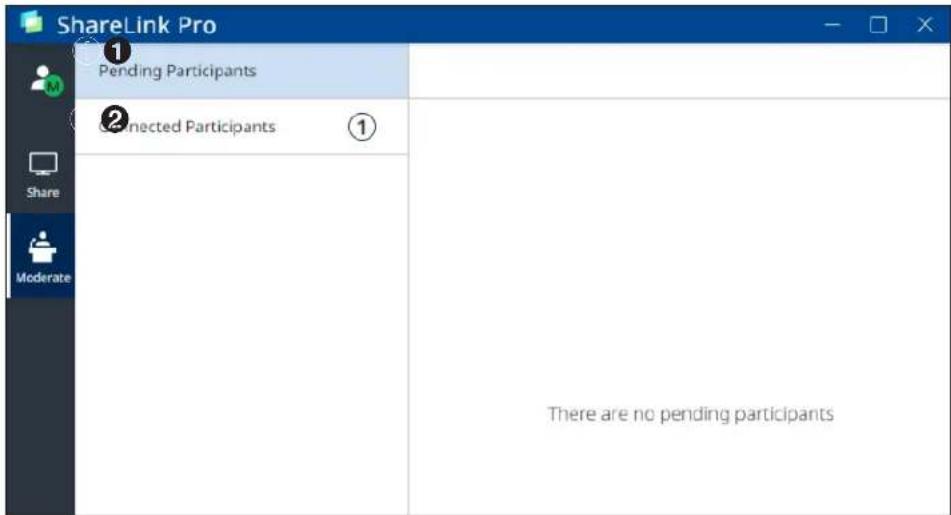
Figure 14. ShareLink Pro Software Moderate Page
① Pending Participants tab — Use this section to manage pending participants.
② Connected Participants tab — Use this section to disconnect any connected participants.
Using the Embedded Web Page
To access the embedded web page, open your web browser and enter the ShareLink Pro IP address into the browser.
NOTE: The IP address is shown on the standby screen (see figure 7, ② on page 10).
The embedded web page contains the following features:
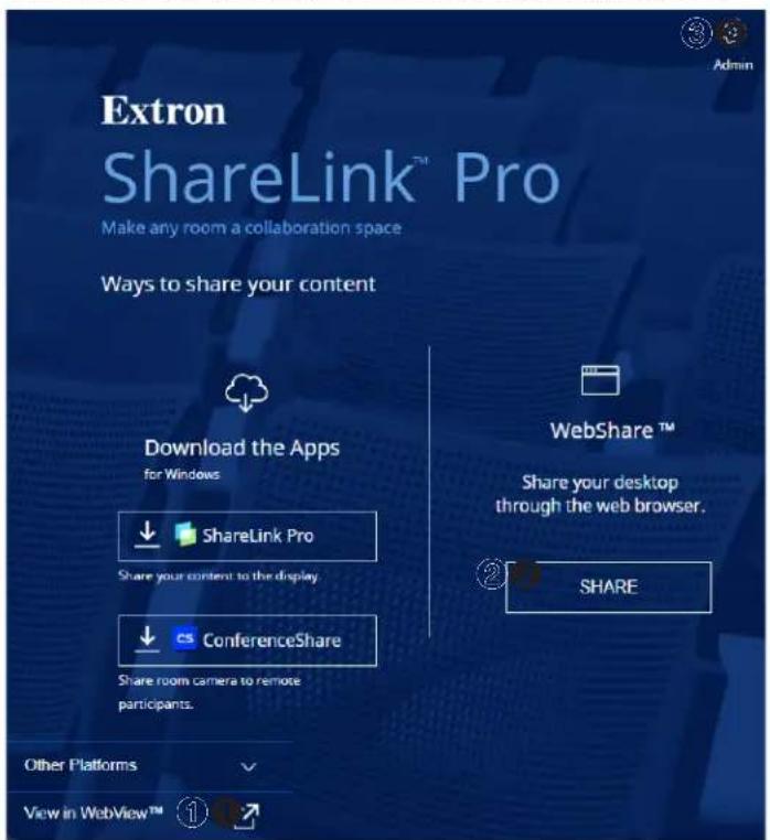
① View in WebView™ — See Viewing a Presentation Using WebView on the next page.
② WebShare — See Presenting a Desktop Using WebShare.
③ Admin — See Using the Admin Page on page 21.
Figure 15. ShareLink Pro Landing Page
NOTE: When selecting an option on the embedded web page:
- If you do not have a trusted SSL Certificate, the browser displays a privacy notification as shown at right.
Continue to the login dialog box as follows:
- Click the button that bypasses the privacy notification (for example, in Chrome, click Advanced [A]). Explanatory text and a link appear.
- Click Proceed to
(unsafe) (B) (or similar message).
Chrome on macOS may not provide an option to proceed.

Your connection is not private
Attackers might be trying to steal your information from 203.0.113.22 (for example, passwords, messages, or credit cards). Learn more
NET:ERR_CERT_AUTHORITY_INVALID

Back to safety
This server could not prove that it is 203.0.113.22, its security certificate is not trusted by your computer's operating system. This may be caused by a misconfiguration or an attacker intercepting your connection.

- Your IT department can provide an uploadable SSL Certificate (see Secure Sockets Layer (SSL) Certificates on page 83). Once the certificate is loaded, the notification does not appear.
Viewing a Presentation Using WebView
The WebView feature allows audience members to view a presentation on their computers or mobile devices through a web browser. The presenter may broadcast the presentation so that the image shown on the display can be viewed remotely.
NOTE: This feature can be disabled using PCS, or a password requirement can be set for using this feature.
Audience members must follow these steps to watch the presentation:
- Open a web browser on the computer or mobile device, and enter the IP address of the ShareLink Pro 2000. The landing page opens as shown in figure 15 on the previous page.
- Click View in WebView (see figure 15, ①). The presentation page opens in the web browser.
NOTE: If necessary, enable WebView in the ShareLink Pro app (see figure 19, 4 on page 29).
Presenting a Desktop Using WebShare
The WebShare feature allows users to present a computer desktop without installing the ShareLink Pro software. Follow these steps to present using WebShare:
NOTE: NAT is required if the ShareLink Pro and the client device are on different subnets. Ensure the client device is inside the NAT to either internet or the ShareLink Pro.
- Open a web browser on the computer or mobile device, and enter the IP address of the ShareLink Pro 2000. The landing page opens as shown in figure 15.
- Click the Share button on the landing page (see figure 15, ②). The login page opens as shown below:
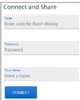
NOTE: The Code and Password fields are shown only if they are enabled in PCS.
- Enter a name in the Your name field. This name is displayed to the audience during presentation.
-
If required, enter the login code in the Code field (the login code is shown on the standby screen; see figure 7, ③ on page 10), and enter the participant password in the Password field.
-
Select what you would like to share (Your Entire Screen, Application Window, or Chrome Tab).
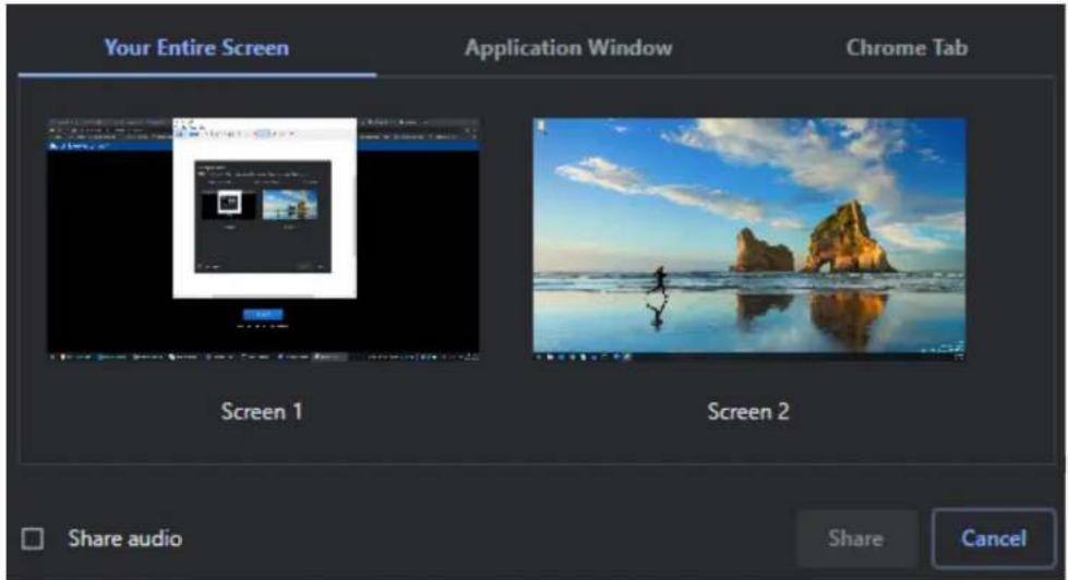
- Click the Share button to start sharing.
NOTE: To share your computer audio, check the Share audio checkbox.
Using the Admin Page
To access the ShareLink Pro admin pages:
- Click the settings icon on the top right corner (see figure 15, ③ on page 18).
-
Enter the user name and password, and click Login.
-
Default user name: admin
- Default password: extron
NOTE: The factory configured password for this device has been set to the device serial number. Passwords are case sensitive. Performing a Reset to Factory Defaults (see page 7) sets the password to extron.
The admin page contains the following panels:
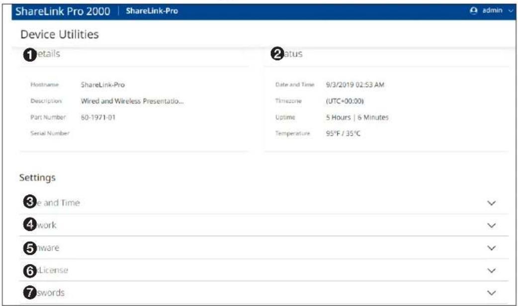
Figure 16. ShareLink Pro 2000 Admin Page
① Details (see next page)
② Status
③ Date and Time
4 Network
⑤ Firmware
6 LinkLicense
⑦ Passwords
① Details (see figure 16 on the previous page) — This panel displays the ShareLink Pro device hostname, product description, part number and serial number.
② Status — This panel displays status information, including date and time, timezone, uptime and temperature.
③ Date and Time — Click Edit to change the device time, date, and time zone. Click Sync to PC to automatically sync the device to the PC time zone.
4 Network — Click Edit to change the device hostname and the network settings (IP address, subnet, and gateway IP address) for the LAN port.
⑤ Firmware — Use this panel to update the device firmware:
- Click Select File to browse to the firmware file.
NOTE: The latest firmware file can be downloaded from the Extron website (see Firmware Download on page 80).
- Select the firmware file, and click Update.
⑥ LinkLicense — Use this panel to upload the LinkLicense file to the
ShareLink Pro 2000. If a LinkLicense has been purchased, upload the file as follows:
a. Click Select File and browse to the LinkLicense (.ell) file on your computer.
b. Select the file, and click Add to upload the file.
⑦ Passwords — Click Edit to change any of the following passwords:
NOTE: The factory configured password for all accounts have been set to the device serial number. Passwords are case sensitive. Performing a Reset to Factory Defaults (see page 7) sets the password to the defaults shown below.
- Admin password (default: extron) — This password is used for accessing the admin page.
- Moderator password (default: moderate) — This password is required to moderate a session.
- Participant password (default: no password) — This password is required to participate in a session.
Enter and confirm the new password, and click Save.
Mirroring a Screen Using the WFA 100 Miracast Adapter
About the WFA 100
The ShareLink Pro WFA 100 (sold separately) is a Wi-Fi Miracast™ adapter that enables anyone to share content from a Windows 10 device to a ShareLink Pro device without installing any software.
NOTE: Minimum requirements for Miracast:
- WFA 100 adapter
- Windows 10 client device (version 2004 or higher recommended)
- Windows Display Driver Model (WDDM) 1.3 Graphics drivers. To verify this driver version, see Miracast Graphics Support on page 48.
- Wi-Fi driver must support Network Driver Interface Specification (NDIS) 6.3 or newer. To verify, see Miracast Wi-Fi Direct Support on page 49.
There are two WFA 100 models: the WFA 100 US (available for the United States) and the WFA 100 EU (for international regions). Both models support 802.11a/b/g/n/ac wireless network standards on 2.4 and 5 GHz bands.
The WFA 100 US supports the following Wi-Fi channels:
• 2G channels: 1, 2, 3, 4, 5, 6, 7, 8, 9, 10, 11
• 5G channels: 36, 40, 44, 48, 149, 153, 157, 161, 165
The WFA 100 EU supports the following Wi-Fi channels:
• 2G channels: 1, 2, 3, 4, 5, 6, 7, 8, 9, 10, 11, 12, 13
• 5G channels: 36, 40, 44, 48
NOTE: For important considerations regarding Miracast performance quality, connection methods, configuration, and troubleshooting see Miracast Connection Using the WFA 100 on page 43.
Using the WFA 100
Follow the steps on the next page to connect and mirror a Windows 10 device using the WFA 100.
NOTES:
- For optimal performance, ensure that the Windows 10 device is on the same network as the ShareLink Pro.
-
To improve end user experience, ensure that the enterprise wireless access points serving the Wi-Fi network maintain high signal strengths and are configured to operate on Wi-Fi channels with the least interference (ideally unoccupied and non-overlapping channels).
-
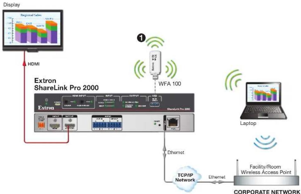
Connect the WFA 100 adapter to the ShareLink Pro front panel USB port (①).
flowchart
graph TD
    A["Display"] --> B["HDMI"]
    B --> C["Extron ShareLink Pro 2000"]
    C --> D["Extron"]
    D --> E["Network"]
    E --> F["Ethernet"]
    F --> G["TCP/IP Network"]
    G --> H["Facility/Room Wireless Access Point"]
    H --> I["Corporate Network"]
    J["Local Device"] --> K["Extron"]
    K --> L["WFA 100"]
    L --> M["Local Device"]
    N["Laptop"] --> O["Local Device"]
    P["Regional Sales"] --> Q["Regional Sales"]
    Q --> R["Regional Sales"]
    R --> S["Regional Sales"]
    T["External"] --> U["External"]
    U --> V["External"]
    V --> W["External"]
    X["Internet"] --> Y["Internet"]
    Y --> Z["Internet"]
    Z --> AA["Internet"]
    AA --> AB["Internet"]
    AC["Data Bus"] --> AD["Data Bus"]
    AD --> AE["Data Bus"]
    AE --> AF["Data Bus"]
    AG["External"] --> AH["External"]
    AH --> AI["External"]
    AI --> AJ["External"]
- Ensure that Wi-Fi is enabled on the Windows 10 client device.
- Press the
keyboard shortcut on the Windows 10 client device to open the Connect panel, which appears at the right of the screen (②).
NOTE: Alternatively, click the Connect quick settings tile in Action Center (shown below) to open this panel.
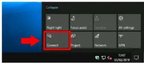
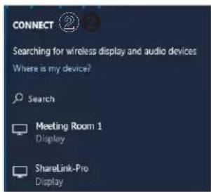
The Connect panel shows a list of Miracast capable devices.
NOTE: Wi-Fi must be enabled in order to discover ShareLink Pro devices.
- Select the desired Sharelink Pro unit from the list, and enter the display code if prompted (③) (see the Standby Screen for the ShareLink Pro hostname and code).
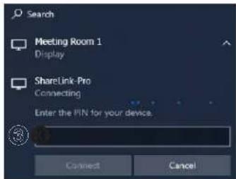
Screen sharing options
Once the ShareLink Pro is connected, the Change projection mode link is shown under the ShareLink Pro hostname.
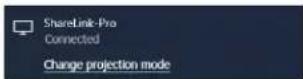
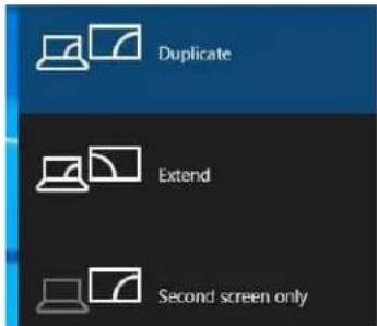
Click Change projection mode to see the following screen sharing options.
- Duplicate mode is the default setting, which mirrors the Windows 10 screen onto the SharePoint Pro output display. This mode is ideal for most projection and casting scenarios.
- Extend mode sets the ShareLink Pro output display as a second monitor.
- Second screen only mode sets the ShareLink Pro output display as the primary monitor.
Disconnecting from the display
To disconnect from the display, return to the Connect panel (using the
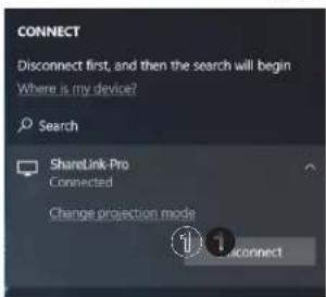
Alternatively, use the
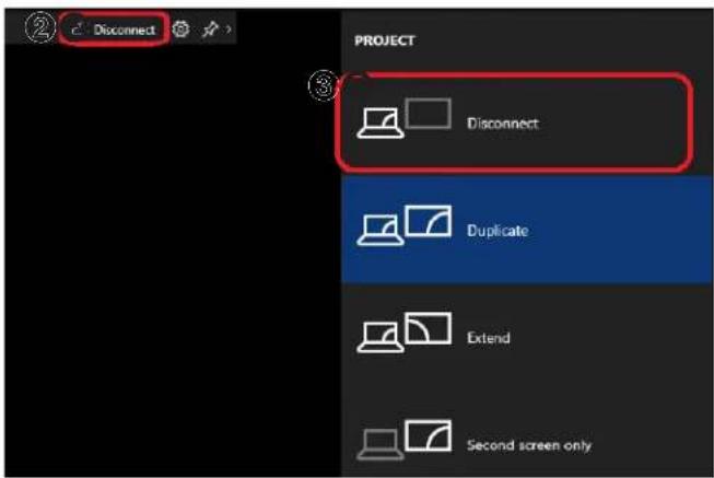
NOTE: For important considerations regarding Miracast performance quality, connection methods, configuration, and troubleshooting see Miracast Connection Using the WFA 100 on page 43.
Operation Using a Mobile Device
The ShareLink Pro Mobile App is supported by Android and Apple mobile devices, including iPad® and iPhone®. It allows users to present photos, web pages, device screenshots, and the device camera (see instructions below).
The ShareLink Pro 2000 also supports screen mirroring for Apple devices.
This section covers the following:
• Downloading the ShareLink Pro App
• Using the ShareLink Pro App
• Using iOS Screen Mirroring
Downloading the ShareLink Pro App
Follow these steps to download the ShareLink Pro mobile app:
- Ensure that the ShareLink Pro is powered and connected to the network.
- Open the Wi-Fi networks list on your device and connect to an external WAP that is on the same network as the ShareLink Pro. Ensure that the WAP and the ShareLink Pro are wired to the same network.
- Navigate to the ShareLink Pro landing page (see figure 17) by entering the device IP address into a browser on the mobile device (see the standby screen for the ShareLink Pro IP address).
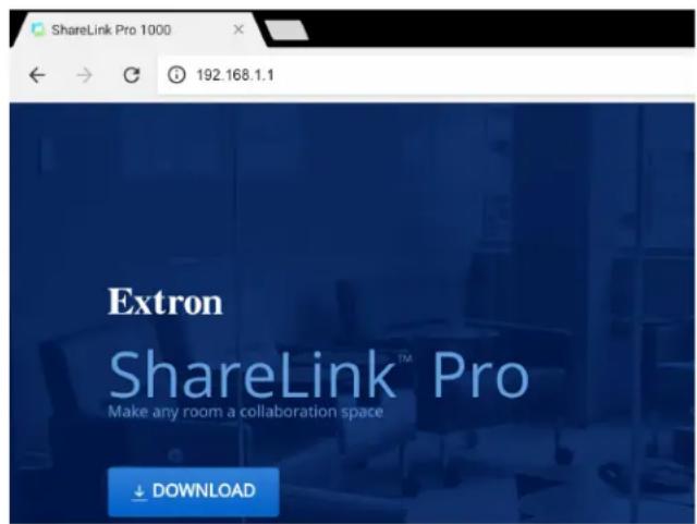
Figure 17. ShareLink Pro Landing Page
- Select Download. The ShareLink Pro app download page opens on the app store for your device.
- Install the app on your mobile device.
Using the ShareLink Pro App
Connecting to a ShareLink Pro Unit
Once the ShareLink Pro app is installed on the device, follow these steps to connect to the ShareLink Pro:
- Ensure that the ShareLink Pro is powered and connected to the network.
- Open the Wi-Fi networks list on your device and connect to an external WAP that is on the same network as the ShareLink Pro. Ensure that the WAP and the ShareLink Pro are wired to the same network.
- Open the ShareLink Pro app and select the desired unit from the list (see the standby screen to verify the device hostname and IP address).
NOTES:
- The ShareLink Pro app automatically discovers ShareLink Pro units in the same subnet as the client device.
- To refresh, drag down and release the list. If the unit is not listed, select the New Connection button at the bottom and enter the hostname or IP address as instructed on the app screen.
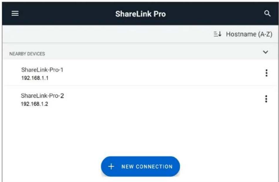
Figure 18. ShareLink Pro Devices List
- When prompted, enter the login code shown on the standby screen.
- When connection is established, the app shows the Share screen (see the next page).
Presenting Content
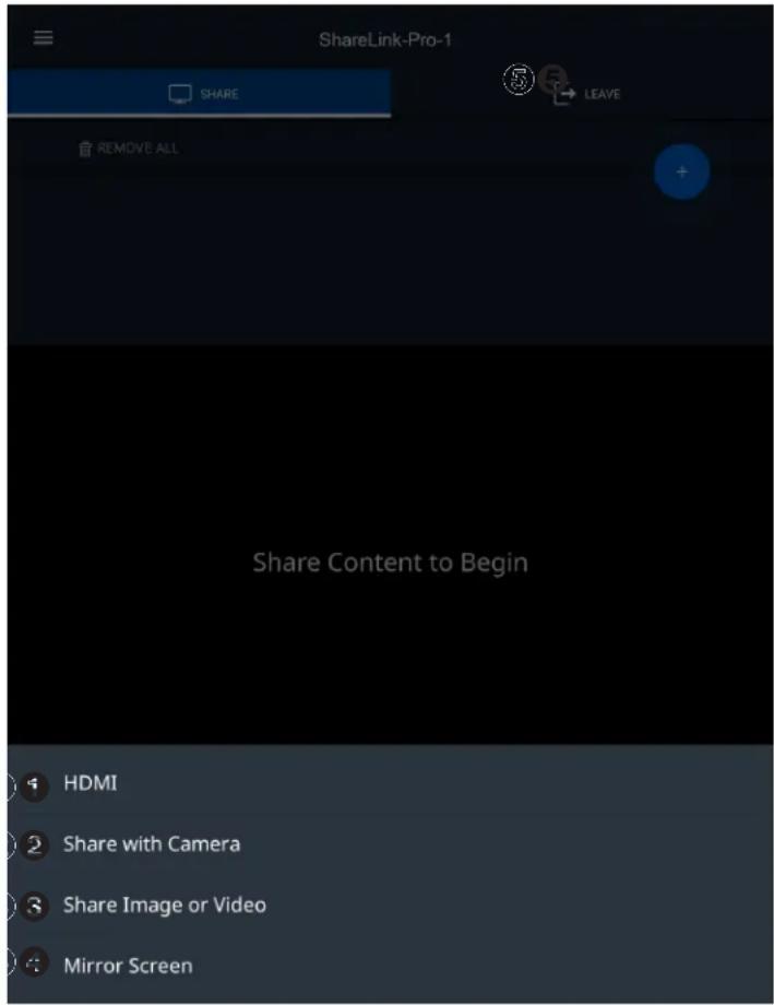
Use the Share screen to present content. Select the +button to see the options below.
NOTE:
- This Share screen also shows the ongoing presentation.
- Up to four presenters can stream content simultaneously. The ShareLink Pro automatically arranges the incoming presentations side by side on the display.
- A moderator can control the content presented by participants during a session (see Moderating a Presentation on page 16 for details).
① HDMI – Click this button to share the connected HDMI source as a window.
② Share with Camera – Click this button to share an image taken by the device camera.
NOTE: For iOS devices, a Share Website option is also available to share the device web browser.
③ Share Image or Video – Click this button to browse to a specific video or image file on your device. Select the video or image file to present it on the display.
④ Mirror Screen – Click this button to automatically mirror your device screen on the display device. Select Stop Presenting to stop the presentation.
NOTE: For iOS devices, follow the on-screen instructions for mirroring the device screen, or see Using iOS Screen Mirroring on page 30.
⑤ Leave – Click this button and select Leave Session to exit the presentation session.
App Menu
Press the menu icon on the top left corner to see the following options:
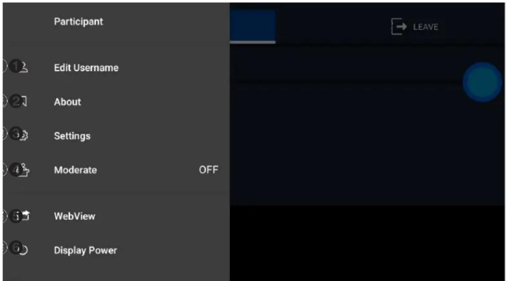
Figure 19. App Menu
① Edit Username — Select this option to edit your Username and Login Settings.
② About — Select this option to see the app version number, Licenses, Terms of Use, and Privacy Policy.
③ Settings — Select this option to view login settings and the EDS settings.
4 Moderate — Select this option to enable Moderator mode (see Moderating a Presentation on page 16 for details).
⑤ WebView — Select this option to enable or disable WebView.
⑥ Display Power — This option opens a page with two buttons (ON and OFF). If the display connected to the output of the SharePoint Pro supports CEC, the ON and OFF buttons may be used to send out unidirectional Power ON and Power OFF commands to the display via CEC.
Using iOS Screen Mirroring
This feature allows iOS device screens to be mirrored onto the display.
- Ensure that the ShareLink Pro 2000 is powered and connected to the network.
- Connect your device to the ShareLink Pro 2000 through Wi-Fi (see step 2 of Connecting to a ShareLink Pro Unit on page 27).
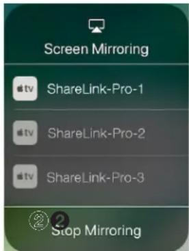
- Open the iOS device control center and select Screen Mirroring (see 1, below).
NOTE: Options may look different depending on the iOS version.
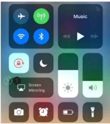
The discovered devices list appears as shown at right.
- Select your ShareLink Pro device from the discovered devices list.
NOTE: If your ShareLink Pro device is not listed because it is on a different subnet, follow the instructions on the next page.
If prompted for a code (as shown below), enter the ShareLink Pro login code (as shown on the standby screen), and press OK.
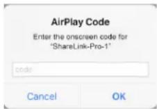

The device screen is immediately mirrored onto the display.
To stop presenting the device screen, select Stop Mirroring (see ②, below).
Discovering a ShareLink Pro Device on a Different Subnet for Apple Screen Mirroring
The ShareLink Pro for iOS mobile app automatically discovers ShareLink Pro devices that are on the same subnet as the iOS device.
If your ShareLink Pro device is not on the same subnet, follow these steps to discover the device using the app.
NOTE: The same steps apply to macOS devices using the ShareLink Pro macOS software.
- Open ShareLink Pro for iOS mobile app.
- Select the New Connection button at the bottom.
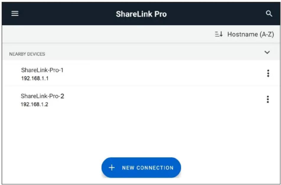
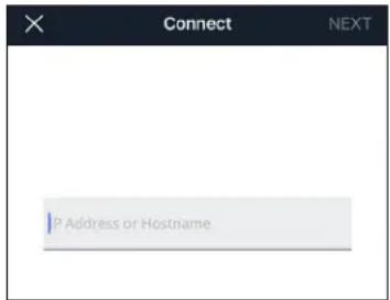
- Enter the IP address or hostname of the ShareLink Pro device that is outside the local subnet.
- Enter a password if prompted.
-
Enter confirmation if prompted.
-
Once the connection has been successfully established and the main sharing page is shown:
-
For iOS devices: Go to the Control Center and navigate to the Screen Mirroring device discovery list (see step 3 on the previous page).
- For macOS devices: Click the AirPlay button in the menu bar as shown below.
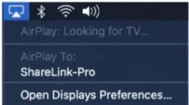
- Select the ShareLink Pro device from the device discovery list (see step 4 on the previous page).
Enterprise Discovery Service
This section covers the following topics on the ShareLink Pro Enterprise Discovery Service:
- Enterprise Discovery Service - Overview
- Selecting and Configuring the EDS Host
- Configuring EDS Clients in PCS
Enterprise Discovery Service - Overview
Enterprise Discovery Service (EDS) is useful in applications involving multiple ShareLink Pro units within a network.
EDS offers a solution for discovery of ShareLink Pro devices across subnets for the ShareLink Pro software (Windows, macOS, iOS, and Android) as well as for Apple devices (macOS and iOS) that support native screen mirroring (AirPlay). Furthermore, EDS reduces the number of steps required for connecting to a ShareLink Pro device via the ShareLink Pro software (Windows, macOS, iOS, and Android).
EDS requires a host device (called the "EDS Host") and multiple client devices (called "EDS Clients"):
- The EDS Host is a ShareLink Pro device designated to operate as the host. This can be any ShareLink Pro device on any subnet deployed on the network. EDS Host functionality is enabled via PCS.
NOTES:
- Enabling EDS Host functionality does not render the ShareLink Pro device non-operational. The ShareLink Pro operates as normal, but with an additional background service running in firmware.
- When selecting an EDS Host device, Extron recommends selecting a ShareLink Pro device where video performance is not critical. Video performance is inversely proportional to the number of EDS Client devices being managed by the EDS Host device.
- EDS Clients are ShareLink Pro devices managed by the ShareLink Pro device operating as the EDS Host. EDS Clients may also be end user mobile devices running ShareLink Pro software (Windows, macOS, iOS, and Android).
Once enabled, the EDS Host operates as a central communication hub between multiple ShareLink Pro devices deployed across multiple subnets across the entire network, as well as between end user mobile devices (phones, tablets, laptops, desktops, etc.) and ShareLink Pro devices on the network.
Configuring the EDS Host "Pointer"
Once the EDS Host device has been selected and EDS Host functionality enabled, all other ShareLink Pro devices must be configured as EDS Clients via PCS.
Once a ShareLink Pro device has been configured as an EDS Client, it begins to "look for" the EDS Host by using the "pointer" configured via PCS. The "pointer" is either the hostname or IP address of the EDS Host device.
The default hostname for the EDS Host device is ExtronEDS. When the EDS Host function is enabled for the first time on a ShareLink Pro device, PCS asks for permission to change the ShareLink Pro device hostname to ExtronEDS. The purpose is to ease and streamline configuration of EDS.
- When a ShareLink Pro device is configured as an EDS Client device, the default "pointer" is ExtronEDS. In other words, all ShareLink Pro devices "look for" the EDS Host via DNS lookup using the default hostname of the EDS Host device which is ExtronEDS by default.
- The latest ShareLink Pro software (Windows, macOS, iOS, and Android), which supports EDS, always operates as an EDS Client and always looks for the EDS Host device via DNS lookup using the default hostname of the EDS Host device (ExtronEDS).
NOTES:
- It is not mandatory to use ExtronEDS as the hostname of the EDS Host device. However, it is highly encouraged since the ShareLink Pro devices and mobile devices running ShareLink Pro software look for the EDS Host device by trying to resolve the hostname ExtronEDS via DNS lookup by default.
- The PCS admin may choose to operate the EDS Host device with any hostname they desire. However, they must configure (via PCS) all other ShareLink Pro devices operating as EDS Clients to point to the EDS Host using the desired hostname of the EDS Host. The mass configuration update feature in PCS may be useful in this case.
- For mobile devices running ShareLink Pro software (Windows, macOS, iOS, and Android), the end user must manually connect to a ShareLink Pro device that has already been configured with the correct pointer (different from ExtronEDS) to the EDS Host. Once a successful connection has been made manually the first time, the ShareLink Pro software automatically updates its pointer to match the pointer in the ShareLink Pro device to which they just connected manually. Therefore, the next time the ShareLink Pro software is opened, it will point to the correct EDS Host and present the end user with the new EDS workflow.
EDS Workflow
Once the correct pointer has been configured:
- ShareLink Pro devices operating as EDS Clients establish a secure communication channel with the EDS Host device and report their connection information to the EDS Host. The EDS Client device also periodically sends a request to the EDS Host to assign it a new Login Code based on a timer configured via PCS or at the end of every session (also configured via PCS).
-
The EDS Host device stores the connection information and associated Login Code for each EDS Client device in an internal database.
-
Mobile devices operating as EDS Clients (by running ShareLink Pro software) establish a secure communication channel with the EDS Host device.
- The client devices then present one of two different connection workflows (as instructed by the EDS Host) to the end user.
NOTE: The connection workflow is configured as a setting on the EDS Host device via PCS as shown below (1) (also see step 4 on the next page).
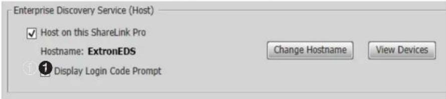
When this box is checked, connection workflow 1 is configured.
When it is un-checked, connection workflow 2 is configured.
The connection workflows are as follows:
- Connection Workflow 1 – Prompts the end user for the Login Code displayed on the output of the ShareLink Pro to which they want to connect. The EDS Client (mobile device running ShareLink Pro software) then passes the Login Code entered by the end user to the EDS Host device. The EDS Host then responds with the connection information of the ShareLink Pro device associated with the received Login Code in its internal database.
This workflow effectively reduces the connection workflow to one simple step (enter Login Code) for the end user.
- Connection Workflow 2 – Proceed directly to the main device discovery page as usual but populate the page with the list of devices stored in the EDS Host's internal database in addition to any devices discovered in the local subnet and any previously manually added devices.
In this case, the EDS Host provides a copy of its internal database to the mobile device running ShareLink Pro software.
This workflow offers a cross-subnet device discovery solution in applications where it is preferred to operate without a Login Code or for users that prefer the traditional device discovery workflow. In other words, the end user is no longer restricted to being able to discover ShareLink Pro devices only on the local subnet.
NOTE: This is a global setting, meaning that the EDS Host instructs all mobile devices operating as EDS Clients to either prompt end user for Login Code (workflow 1) or to proceed directly to the device discovery page (workflow 2).
Selecting and Configuring the EDS Host
EDS can be enabled using the Product Configuration Software (PCS).
A ShareLink Pro unit must be selected to act as the EDS Host within the network. The ShareLink Pro unit hosting the Enterprise Discovery Service acts as a central communication hub between client devices (such as phones, tablets, and laptops) and the ShareLink Pro devices on the network.
NOTE: Depending on how many client devices are connected, EDS may affect the audio and video performance of the ShareLink Pro device acting as the EDS Host. This should be taken into consideration when selecting the EDS Host device.
Configuring the EDS Host in PCS
Follow these steps to enable EDS on the host device using PCS.
- Open PCS v4.10.5 or greater.
- Connect to the ShareLink Pro unit to be assigned as the EDS Host.
-
Navigate to General Settings > Display Setup tab.
-
Click the Host on this ShareLink Pro checkbox in the Enterprise Discovery Service panel.
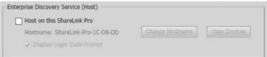
5. Click OK:
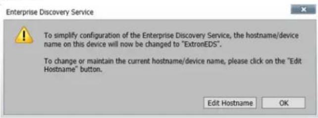
Configuring EDS Clients in PCS
Enabling EDS in Client Devices
Follow these steps to enable EDS for client devices. Repeat these steps for each
ShareLink Pro unit to be assigned as an EDS Client within the network, including the EDS Host.
NOTE: The ShareLink Pro device operating as the EDS Host can also operate as an EDS Client. In this case, it is operating as a client of itself. This is possible since the EDS Host function operates independently in firmware.
- Open PCS v4.10.5 or greater.
- Connect to the ShareLink Pro to be assigned as an EDS Client.
- Navigate to General Settings > Display Setup tab.
- Click the Enterprise Discovery Service radio button in the Confirmation Type panel.
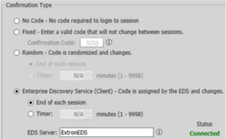
NOTE: If an EDS Client is failing to connect to the EDS Host, change the client's confirmation type to No Code for a minute before switching it back to Enterprise Discovery Service. If the connection issue persists, then power cycle the EDS Client.
The hostname (displayed in the EDS Server field) is set to ExtronEDS by default.
NOTES:
- It is highly recommended that the default hostname (ExtronEDS) not be changed. By default, ShareLink Pro units are configured to look for the ExtronEDS hostname.
-
If the hostname is changed, all other ShareLink Pro units within the network will need to be configured to look for the newly assigned hostname (see step 5).
-
Only perform this step if you chose to change the default EDS hostname: Enter the new hostname or the IP address of the EDS Host in the EDS Server field.
- Repeat steps 1 - 5 on all other ShareLink Pro units in the network to configure them as EDS Clients. If you changed the default EDS hostname, enter the new hostname.
Managing Login Code Settings for EDS Clients
Follow these steps to configure the login code settings for client devices (this configuration is done on the EDS Host via PCS).
- Open PCS v4.10.5 or greater.
- Connect to the ShareLink Pro assigned as the EDS Host.
-
Navigate to General Settings > Display Setup tab.
-
Click View Devices (①) in the Enterprise Discovery Service panel.
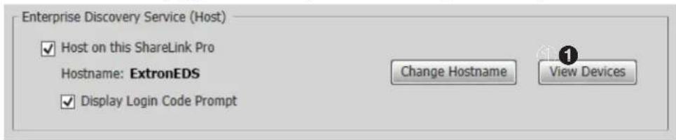
This opens a list of all ShareLink Pro devices operating as EDS Clients (reporting to the EDS Host):
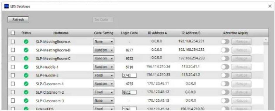
- Use the Code Setting drop-down list in each row to configure the code setting (None, Fixed, or Random) for each EDS Client as desired.
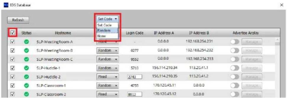
To configure all EDS Clients to operate with the same Code Setting: Check the top left checkbox to select all devices, then use the Set Code drop-down list at the top to configure the Code Setting for all EDS Clients at once.
Other Configuration Options
This section covers the following configuration options for the ShareLink Pro:
• Device Discovery using ShareNext™
• Digital Signage Feature
• Miracast Connection Using the WFA 100
Device Discovery using ShareNext™
ShareNext uses Bluetooth technology to discover nearby ShareLink Pro devices equipped with a WFA 100. This is useful in applications where client devices and ShareLink Pro devices are in separate subnets within a network. Client devices discover the ShareLink Pro via Bluetooth, but they will still connect to the ShareLink Pro over the network. It is imperative that client devices have Bluetooth enabled and have a routable network path to the ShareLink Pro.
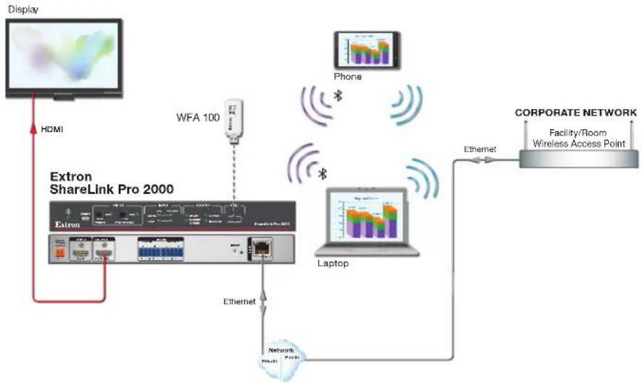
flowchart
graph TD
    A["Display"] -->|HDMI| B["Extron ShareLink Pro 2000"]
    B --> C["Extron"]
    C --> D["Network Node"]
    D --> E["Laptop"]
    E --> F["Phone"]
    F --> G["Corporate Network"]
    G --> H["Facility/Room Wireless Access Point"]
    B --> I["WFA 100"]
    I --> J["Ethernet"]
    J --> D
    style A fill:#f9f,stroke:#333
    style B fill:#ccf,stroke:#333
    style C fill:#cfc,stroke:#333
    style D fill:#fcc,stroke:#333
    style E fill:#cff,stroke:#333
    style F fill:#ffc,stroke:#333
    style G fill:#fcc,stroke:#333
    style H fill:#cfc,stroke:#333
    style I fill:#fcc,stroke:#333
ShareNext works with client devices using ShareLink Pro software (Windows, macOS, iOS, and Android) as well as Apple devices (macOS and iOS) that support native screen mirroring (AirPlay).
NOTE:
- ShareLink Pro devices must be equipped with the WFA 100 adapter in order for ShareNext to be enabled.
- The client devices must be able to access the ShareLink Pro over the network to discover it.
Using ShareNext with the ShareLink Pro Software and Mobile App
The ShareLink Pro software or mobile app scans for all nearby ShareLink Pro units equipped with a WFA 100. If one is discovered, the user is given an option to connect to the nearby ShareLink Pro. If multiple devices are discovered, the device discovery page displays all the detected ShareLink Pro devices.
Using ShareNext with Apple Screen Mirroring
Apple devices (iOS and macOS) can natively discover nearby ShareLink Pro devices. All nearby ShareLink Pro units equipped with a WFA 100 are discovered and visible in the iOS and macOS screen mirroring device discovery list.
Digital Signage Feature
The ShareLink Pro can be used as a web-based digital signage player when it is not being used for collaboration. This feature allows the ShareLink Pro to access cloud-hosted digital signage content. Follow the steps below to enable the digital signage feature using PCS.
NOTE: This feature is available only with a LinkLicense.
- Open PCS v4.10.5 or greater.
- Connect to the ShareLink Pro device.
- Navigate to Logo Config > Web Content tab.
- Within the Web URL field (①), enter the URL generated by your digital signage Software as a Service (SaaS) provider.
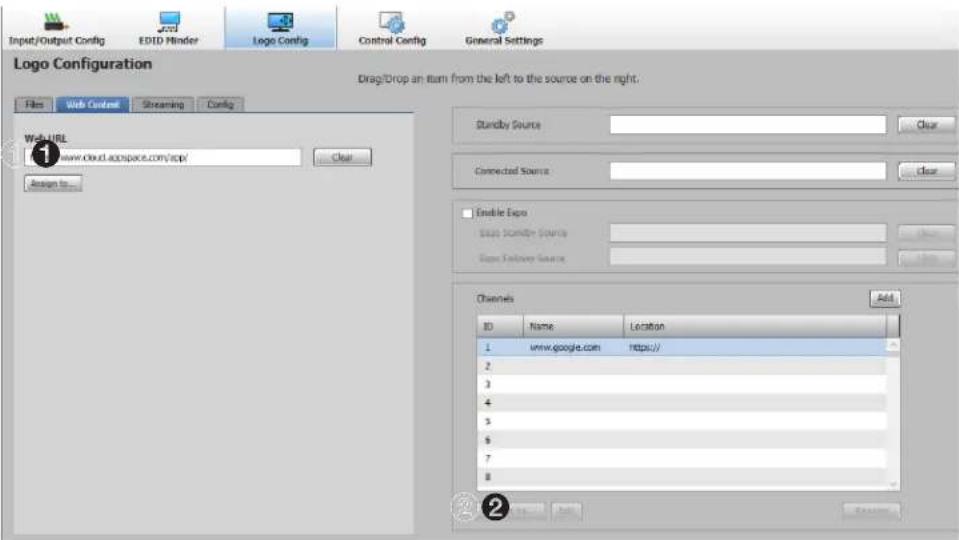
- Click the Assign To... button (②).
6. Select one of the following options:
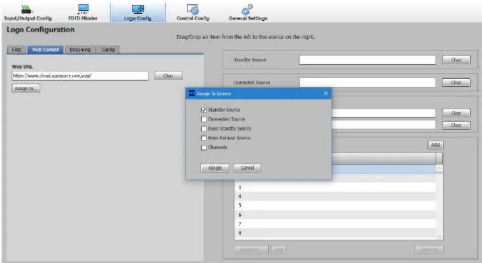
- Assign to Standby – This option assigns the web URL content as a playback source in the Standby state.
- Assign to Connected – This option assigns the web URL content as a playback source in the Connected state.
- Assign to Expo Standby – This option assigns the web URL content as a playback source in the Expo Standby state.
- Assign to Expo Failover – This option assigns the web URL content as a playback source in the Expo Failover state.
- Assign to Expo Channel – This option assigns the web URL content as a playback source for a specific channel in Expo Mode.
The web URL entered in the text field is copied as a source for the next available Expo channel. For example, if channels 1, 2, 3, and 4 have already been configured, then the web URL is configured as the source for channel 5.
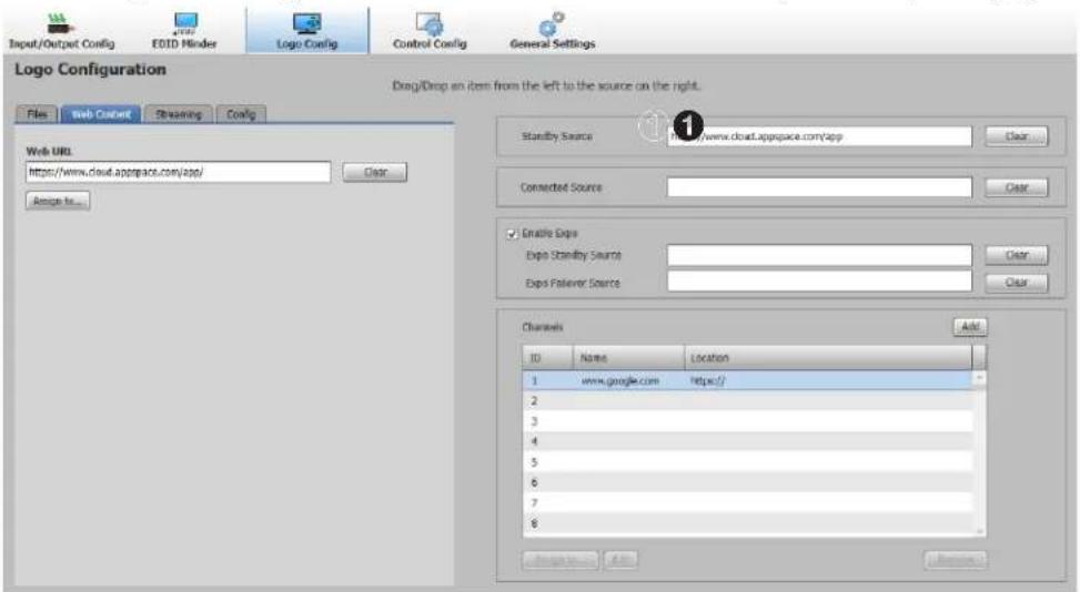
7. Click Assign. The assigned web URL is shown on the Standby Source panel (①):
Miracast Connection Using the WFA 100
Miracast Overview
Miracast is a standard for wireless connections introduced by the Wi-Fi Alliance. It enables the sharing of content wirelessly from mobile devices to displays.
The ShareLink Pro 2000 supports Miracast technology when used with the ShareLink Pro WFA 100 adapter (see About the WFA 100 on page 23).
There are two ways to connect and share content via Miracast.
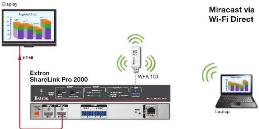
- Miracast Wi-Fi Direct - This method involves a peer-to-peer connection that relies on Wi-Fi Direct technology. In this method, both device discovery and the sharing of content is facilitated over the Wi-Fi Direct connection.
flowchart
graph TD
    A["Display"] --> B["Extron ShareLink Pro 2000"]
    B --> C["HDMI"]
    C --> D["Extron"]
    D --> E["Wi-Fi Direct"]
    E --> F["Laptop"]
    style A fill:#f9f,stroke:#333
    style B fill:#ccf,stroke:#333
    style C fill:#cfc,stroke:#333
    style D fill:#fcc,stroke:#333
    style E fill:#cff,stroke:#333
    style F fill:#ffc,stroke:#333
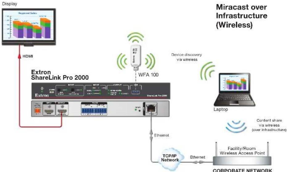
- Miracast over Infrastructure (default) - In this method, device discovery is performed initially over Wi-Fi Direct, but the content is shared over an existing wireless network connection between the Windows 10 laptop and the ShareLink Pro.
flowchart
graph TD
    A["Display"] --> B["HDMI"]
    B --> C["Extron ShareLink Pro 2000"]
    C --> D["WFA 100"]
    D --> E["Laptop"]
    E --> F["Content share via wireless (over infrastructure)"]
    F --> G["TCP/IP Network"]
    G --> H["Facility/Room Wireless Access Point"]
    H --> I["Corporate Network"]
    C --> J["Device discovery via wireless"]
    J --> K["Internet"]
    style A fill:#f9f,stroke:#333
    style B fill:#f9f,stroke:#333
    style C fill:#ccf,stroke:#333
    style D fill:#ccf,stroke:#333
    style E fill:#cfc,stroke:#333
    style F fill:#fcc,stroke:#333
    style G fill:#cff,stroke:#333
    style H fill:#ffc,stroke:#333
    style I fill:#fcc,stroke:#333
Miracast over Infrastructure is the default connection method while Wi-Fi Direct is the failover connection method. This means that, by default, Windows 10 prefers Miracast Over Infrastructure connections, and will always attempt to connect to the ShareLink Pro over the existing network connection. If Windows determines that a network connection does not exist, then it proceeds to connect over Wi-Fi Direct.
NOTES:
- For Wi-Fi Direct connections, connection quality depends on the proximity of the client device to the WFA 100 (attached to the ShareLink Pro). For optimal performance, it is highly recommended that you keep your Windows 10 device within 50 ft (\~15m) of the WFA 100/ShareLink Pro.
- For Miracast Over Infrastructure connections, connection quality depends on the proximity of the client device to the enterprise wireless access point serving the existing Wi-Fi network (to which the ShareLink Pro device is connected). For optimal performance, it is highly recommended that you keep your Windows 10 device within 50 ft (\~15m) of both the WFA 100/ShareLink Pro and enterprise wireless access point.
Miracast Connection Methods
Although Miracast always works from a connection standpoint, the performance varies depending on the connection method. Three different configuration options are possible and are listed below in order of decreasing performance from top to bottom.
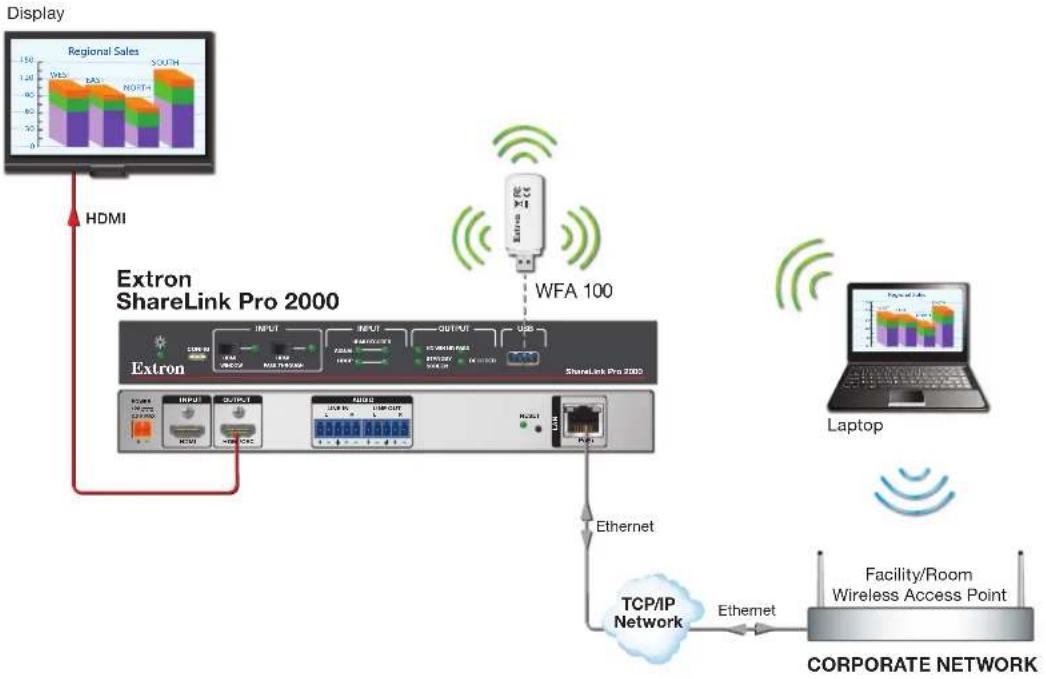
Option 1
Windows 10 device connected to the same Wi-Fi network as the ShareLink Pro devices:
flowchart
graph TD
    A["Display"] --> B["Extron ShareLink Pro 2000"]
    B --> C["Extron"]
    C --> D["Networks"]
    D --> E["WFA 100"]
    E --> F["Laptop"]
    F --> G["Facility/Room Wireless Access Point"]
    G --> H["TCP/IP Network"]
    H --> I["Ethernet"]
    I --> J["Networks"]
    J --> K["Extron"]
    K --> L["HDMI"]
    style A fill:#f9f,stroke:#333
    style B fill:#ccf,stroke:#333
    style C fill:#cfc,stroke:#333
    style D fill:#fcc,stroke:#333
    style E fill:#cff,stroke:#333
    style F fill:#ffc,stroke:#333
    style G fill:#cfc,stroke:#333
    style H fill:#fcc,stroke:#333
    style I fill:#ffc,stroke:#333
    style J fill:#fcc,stroke:#333
    style K fill:#cfc,stroke:#333
    style L fill:#fcc,stroke:#333
Option 2
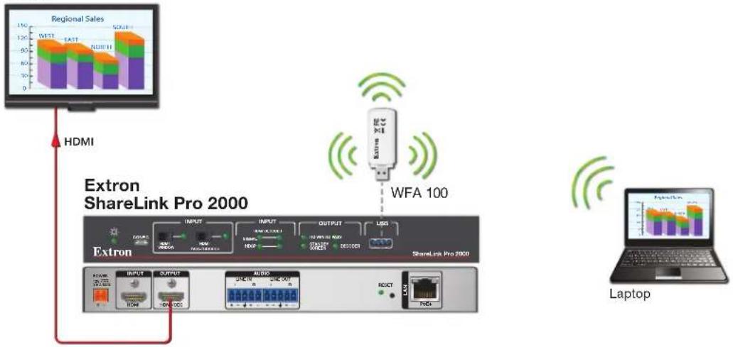
Windows 10 device not connected to any Wi-Fi network (but Wi-Fi is still enabled):
Display
flowchart
graph TD
    A["Regional Sales"] --> B["Extron ShareLink Pro 2000"]
    B --> C["Extron"]
    C --> D["Input"]
    C --> E["OUTPUT"]
    C --> F["AUDIO"]
    C --> G["LED"]
    C --> H["RS/INT"]
    C --> I["RS/OUT"]
    C --> J["RS/INT"]
    C --> K["RS/OUT"]
    C --> L["RS/INT"]
    C --> M["RS/OUT"]
    C --> N["RS/INT"]
    C --> O["RS/OUT"]
    C --> P["RS/INT"]
    C --> Q["RS/OUT"]
    C --> R["RS/INT"]
    C --> S["RS/OUT"]
    C --> T["RS/INT"]
    C --> U["RS/OUT"]
    C --> V["RS/INT"]
    C --> W["RS/OUT"]
    C --> X["RS/INT"]
    C --> Y["RS/OUT"]
    C --> Z["RS/INT"]
    C --> AA["RS/OUT"]
    C --> AB["RS/INT"]
    C --> AC["RS/OUT"]
    C --> AD["RS/INT"]
    C --> AE["RS/OUT"]
    C --> AF["RS/INT"]
    C --> AG["RS/OUT"]
    C --> AH["RS/INT"]
    C --> AI["RS/OUT"]
    C --> AJ["RS/INT"]
    C --> AK["RS/OUT"]
    C --> AL["RS/INT"]
    C --> AM["RS/OUT"]
    C --> AN["RS/INT"]
    C --> AO["RS/OUT"]
    C --> AP["RS/INT"]
    C --> AQ["RS/OUT"]
    C --> AR["RS/INT"]
    C --> AS["RS/OUT"]
    C --> AT["RS/INT"]
    C --> AU["RS/OUT"]
    C --> AV["RS/INT"]
    C --> AW["RS/OUT"]
    C --> AX["RS/INT"]
    C --> AY["RS/OUT"]
Option 3
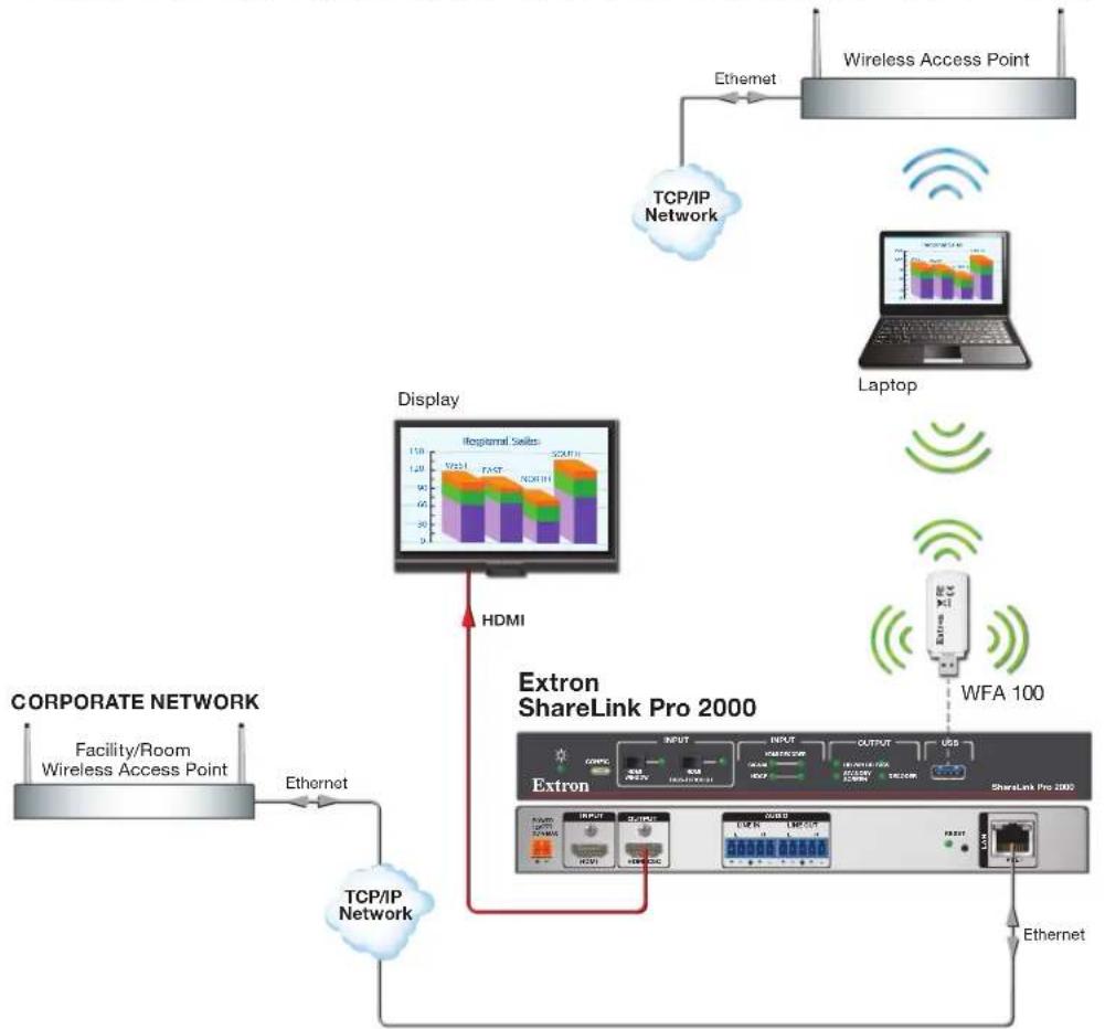
Windows 10 device is not connected to the same Wi-Fi network as the ShareLink Pro devices:
flowchart
graph TD
    A["Corporate Network"] -->|Ethernet| B["TCP/IP Network"]
    B --> C["Extron ShareLink Pro 2000"]
    C -->|HDMI| D["Display"]
    D --> E["Laptop"]
    E --> F["WFA 100"]
    F --> G["Wireless Access Point"]
    C --> H["Extron"]
    H --> I["Internet"]
    I --> J["USB"]
    J --> K["Wi-Fi"]
    K --> L["Network"]
    style A fill:#f9f,stroke:#333
    style B fill:#ccf,stroke:#333
    style C fill:#cfc,stroke:#333
    style D fill:#fcc,stroke:#333
    style E fill:#cff,stroke:#333
    style F fill:#ffc,stroke:#333
    style G fill:#fcc,stroke:#333
    style H fill:#ffc,stroke:#333
    style I fill:#cfc,stroke:#333
    style J fill:#fcc,stroke:#333
    style K fill:#ffc,stroke:#333
    style L fill:#fcc,stroke:#333
NOTES:
- Performance also depends on the quality of the Windows 10 hardware, the wireless environment, and the overall performance of the Wi-Fi network. The strength of the wireless signal could have an adverse impact on connection quality and potentially cause considerable packet loss. Low signal strengths may prevent connections between Windows 10 client devices and the ShareLink Pro. Even if a connection is established, low signal strengths may cause low frame rate, high latency, poor audio and/or video quality, and dropped connections.
-
To improve end user experience, the following is recommended:
-
Ensure that the enterprise wireless access points serving the Wi-Fi network maintain high signal strengths and are configured to operate on Wi-Fi channels with the least interference (ideally unoccupied and non-overlapping channels).
- Ensure that the WFA 100 attached to ShareLink Pro devices are also configured (via PCS) to operate on Wi-Fi channels with the least interference (ideally unoccupied and non-overlapping channels). For WFA 100 channel configuration instructions, see the next page.
- Perform a scan of the environment using wireless survey equipment that is regularly calibrated, and make note of areas with low or no wireless coverage on a map. Introduce wireless coverage where needed as necessary by adjusting physical access point locations, channel selections, and channel bandwidths. Access point power levels may also require tweaking for optimal performance.
- Configure quality-of-service on networking equipment (switches, routers, wireless LAN controllers, etc.) to prioritize Miracast traffic. Miracast packets are marked as CS5 with DSCP Value = 101 000 and Decimal Value = 40.
- Minimize the number of network hops between the wireless access point and the ShareLink Pro device.
- Refer to the Miracast Setup Guide available on the Extron website for more network design considerations.
Configuring the WFA 100 Channel
The ShareLink Pro supports Miracast Wi-Fi Direct on both the 2.4 GHz band and 5 GHz band. You may configure the channel and other Miracast settings in PCS as shown below.
NOTE: It is highly recommended that you configure the Miracast Wi-Fi Direct channel such that it does not conflict with the enterprise wireless access point channels (for Miracast Over Infrastructure Wi-Fi network). Operating wireless devices on the same or overlapping channels may result in a poor end user experience.
- Open PCS v4.10.5 or greater.
- Connect to the ShareLink Pro device.
- Navigate to General Settings > Access/Role Setup tab:
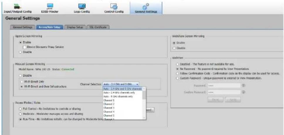
-
Configure the following settings within the Miracast Screen Mirroring panel:
-
Disable – Select this option to disable Miracast screen mirroring.
- Wi-Fi Direct Only – Select this option to always share Miracast content via Wi-Fi Direct (see Miracast Connection Using the WFA 100 on page 43 for details).
- Wi-Fi Direct and Over Infrastructure – Select this option to share Miracast content via the Over Infrastructure method (as priority), with Wi-Fi Direct as the failover method (see Miracast Connection Using the WFA 100 on page 43 for details).
-
Channel Selection – Select the desired channel from this drop-down menu. Miracast will operate in the specified channel. Alternatively, the following auto selection options are available:
-
Auto - 2.4 GHz and 5 GHz channels – On this option, the ShareLink Pro auto selects the channel. It searches for unused channels in the 2.4 and 5 GHz bands (prioritizing 5 GHz channels, then 2.4 GHz)
- Auto - 2.4 GHz channels only – The ShareLink Pro searches for unused channels in the 2.4 GHz band only.
- Auto - 5 GHz channels only – The ShareLink Pro searches for unused channels in the 5 GHz band only.
NOTE: Auto channel selection is initiated at power up, and once every 24 hours when the ShareLink Pro and Miracast is not in use.
Miracast Troubleshooting
Use the following information to troubleshoot Miracast connection issues.
Supported platforms
The ShareLink Pro only supports Windows 10 version 1903 and later. For best experience, Extron recommends version 2004 or later.
Network ports
Miracast requires the following ports to be open on the client device as well as on the overall network: 5353, 7236, 7250 (see the Firewall Traversal table on page 81 for details on these ports).
Miracast Graphics Support
Follow these steps to verify Miracast graphics support on your Windows 10 device.
- Open Start menu.
- Enter "Run" to execute the Run app.
- Type in "dxdiag" and hit the
key.
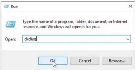
- Click the Display tab (④).
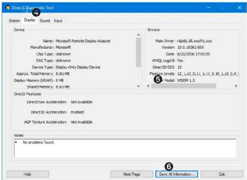
-
Verify that WDDM (Windows Display Driver Model) is version 1.3 or later (⑤). If the WDDM version is lower than 1.3, update the graphics driver.
-
Click the Save all information button (⑥) and save the text (.txt) file.
-
Open the saved text file.
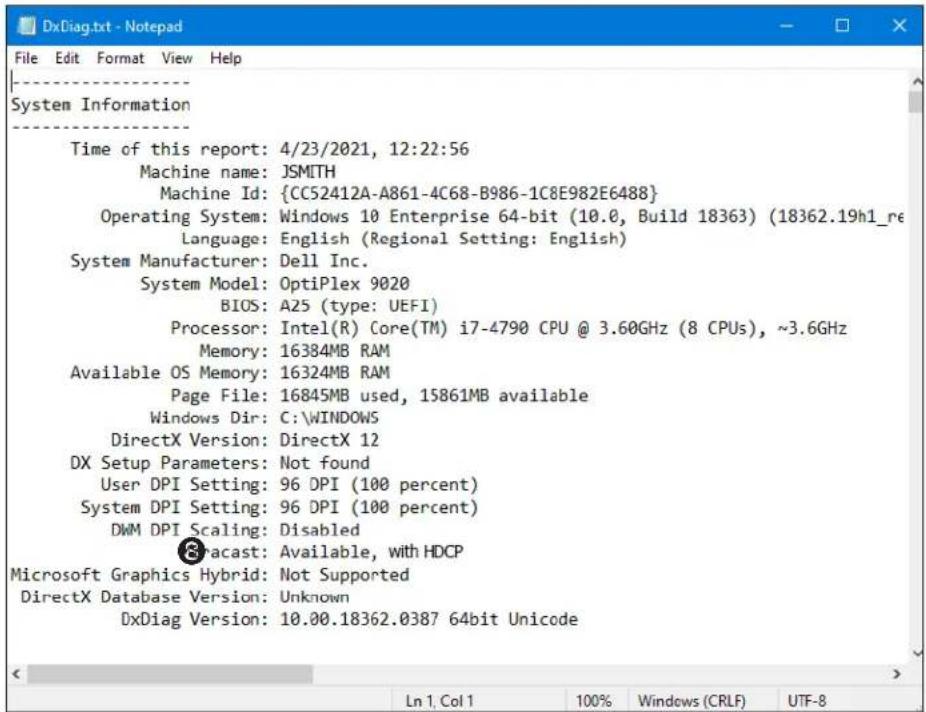
- Check the Miracast (⑧) line to verify that Miracast is available.
Miracast Wi-Fi Direct Support
Follow these steps to verify Miracast Wi-Fi direct support on your Windows 10 device.
- Open the Start menu.
- Enter "cmd" to execute the Command Prompt app.
- Type in "powershell" then hit the
key. - Type in "Get-netadapter|select Name, ndisversion" then hit the
key. - Verify that the NDIS (Network Driver Interface Specification) version for the Wi-Fi interface is version 6.30 or greater (⑤).
![Command Prompt - powershell Microsoft Windows [Version 10.0.18363.1621] (c) 2019 Microsoft Corporation. All rights reserved. H:\>powershell Windows PowerShell Copyright (C) Microsoft Corporation. All rights reserved. Try the new cross-platform PowerShell https://aka.ms/pscore6 PS H:\> Get-netadapter|select Name, ndisversion Name NdisVersion ---- Bluetooth Network Connection 6.30 Local Area Connection 6.30 Wireless Network Connection 6.30 ⑤⑤ PS H:\>](/content/2026/05/942280/images/3345e2eae85630259f3f7acb594dc5b933595ae095512383fb6f272f6a8dddca.jpg)
- If the NDIS version is lower than 6.30, update the Wi-Fi adapter driver.
SIS Configuration and Control
This section contains SIS communication details and SIS commands and responses for the ShareLink Pro 2000. Topics in this section include:
- Host Device Connection
• SIS Overview
• Command and Response Tables for SIS Commands
Host Device Connection
Use a connected computer running an SSH client such as PuTTY to send and receive SIS commands and responses.
Use port 22023 for connection to the ShareLink Pro when using a control system. Enter the admin username and password when prompted.
NOTE: The factory configured password for all accounts have been set to the device serial number (passwords are case sensitive). Performing a Reset to Factory Defaults (see page 7) sets the password to extron.
SIS Overview
Host and Device Communication
SIS commands consist of one or more characters per field. No special characters are required to begin or end a command sequence. When the ShareLink Pro determines that a command is valid, it executes the command and sends a response to the host device. All responses from the device to the host end with a carriage return and a line feed
(CR/LF = ←), which signals the end of the response character string. A string is one or more characters.
Error Responses
When the ShareLink Pro receives an SIS command and determines that it is valid, it performs the command and sends the corresponding response to the host device. If the command is determined invalid or contains invalid parameters, the device returns an error response to the host. The error response codes are:
E10 = Invalid command
E11 = Invalid preset number
E13 = Invalid parameter
E14 = Not valid for this configuration
E17 = Invalid command for signal type
E22 = Busy
E24 = Privilege violation
E35 = Account does not exist
Command and Response Tables Overview
The command and response tables for SIS commands list the commands the device recognizes as valid, the responses returned to the host, a description of the command function or results of executing the command, and some examples of commands in ASCII.
NOTE: Upper and lowercase text can be used interchangeably unless otherwise stated.
Symbol Definitions
The table below shows the hexadecimal equivalent of ASCII characters used in the command and response tables. Hexadecimal values include two digits. The following symbols are commonly used throughout the command and response tables.
| ASCII and Hexadecimal Conversion Table | |||||||||||||||||
| Second Hexadecimal Digit | |||||||||||||||||
| 0 1 | 2 3 | 4 5 | 6 | 7 8 | 9 | A B | C D | E F | |||||||||
| First Hexadecimal Digit | 0 | LF | ← | ||||||||||||||
| 1 | Esc | ||||||||||||||||
| 2 | ● | ! | “ | # | $ | % & | ‘ | ( ) | * | + , | - . | / | |||||
| 3 | ∅ 1 | 2 3 | 4 5 | 6 | 7 | 8 | 9 | : ; | < = | > ? | |||||||
| 4 | @ A | B C | D E | F G | H I | J K | L M | N O | |||||||||
| 5 | P Q | R S | T U | V W | X Y | Z [ | \ ] | ^ _ | |||||||||
| 6 | ` a b c | d e | f g | h i | j k | l m | n o | ||||||||||
| 7 | p q | r s | t u | v w | z y | z { | | } | ~ | |||||||||
← = Carriage return and line feed (LF)
← = Carriage return with no line feed
| = Pipe (can be used interchangeably with the ← character).
- = Space
Esc = Escape key
W = Can be used interchangeably with the Esc character.
x1 = Input window status θ = HDMI window not displayed 1 = HDMI window displayed
x2 = Input signal θ = No input signal detected 1 = Input signal detected
X3 = HDMI Input Signal Detected Rate (Ex: 1920x1080@60.00Hz); no signal = 0000x0000@00.00Hz
x4 = Video format θ = No signal, 1 = DVI, 2 = HDMI
x5 = EDID table slot
x6 = Native resolution & refresh rate Ex: 1920x1080@60.00Hz
x7 = EDID data in Hex
x8 = Output rate (see table on page 64)
X9 = Output sync mode θ = Sync always active (default)
1 = No signal present timer, disable output
2 = Inactivity timer, disable output
x10 = Time out duration θ-999999 (1 second increments)
1000000 = Never times out
Default = 30 seconds
| X11 = Output sync mode status | θ = Active input detected; timer not running1 = No active input; timer is running; output sync still active2 = No active input; timer has expired; output sync disabled |
| X12 = Color bit depth | θ = Auto mode (default) 1 = Force 8-bit |
| X13 = Output video format | θ = Auto (default) 1 = DVI RGB 4:4:4 Full2 = HDMI RGB 4:4:4 Full 3 = HDMI RGB 4:4:4 Limited4 = HDMI YUV 4:4:4 Limited 5 = HDMI YUV 4:2:2 Limited6 = HDMI YUV 4:2:0 Limited |
| X14 = HDCP status | θ = Not connected 1 = Not HDCP Encrypted2 = HDCP Encrypted |
| X15 = HDCP authorized status | θ = HDCP authorize off 1 = HDCP authorize on (default) |
| X16 = HDCP mode | θ = Follow input (default)1 = Always encrypt2 = Follow input with continuous DVI trials3 = Always encrypt with continuous DVI trials4 = Disable authentication |
| X17 = HDCP notification | θ = Black screen1 = Green screen (default) |
| X18 = Video mute status | θ = Unmute (default)1 = Mute video2 = Mute sync |
| X19 = Audio mute status | θ = Unmute (default) 1 = mute |
| X21 = Input type | 1 = HDMI 2 = Decoder (for all decoder streams)3 = Airplay streams 4 = Uploaded image/video content |
| X22 = Input aspect ratio setting | 1 = Fill 2 = Follow (default) |
| X23 = Volume adjustment range | -100 to θ = (default is -30 dB) |
| X28 = Executive mode | θ = Off (default)1 = On |
| X30 = Unit name | Alpha-numeric up to 63 characters. No blanks, spaces, or special characters except hyphen (-). |
| X31 = Default unit name | Alpha-numeric name. ShareLink-Pro-xx-xx-xx(where xx-xx-xx is the last six digits of the unique MAC address). |
| X32 = Firmware version (Ex: 1.00) | |
| X33 = Firmware version and build version (Ex: 1.00.0010) | |
| X34 = Internal temperature (2 digits, °C) | |
| X35 = Verbose response mode | θ = Clear (none) (default), 1 = Verbose mode,2 = Tagged responses, 3 = Verbose + tagged responses |
| X36 = Layout mode | 1 = Layout group #1 (default) 2 = Layout group #23 = Layout group #3 4 = Layout group #45 = Layout group #5 |
| X37 = Current layout number (1-15) | |
| X38 = HDMI input mode | θ = Disabled 1 = Enabled (default) |
| X39 = Apple screen mirroring mode | θ = Disabled 1 = Enabled (default) |
| X391 = Device discovery proxy service | θ = Disabled (default) 1 = Enabled |
| X40 = HDMI controls setting | θ = Disabled 1 = Enabled (default) |
| X41 = Client app controls label | UTF-8 characters permitted, maximum of 16 characters |
| X401 = HDMI client app controls | θ = Hide 1 = Show (default) |
| X42 = Access mode | 1 = Full control 2 = Moderated 3 = Run-time (default) |
| X402 = WebShare mode | θ = Disabled 1 = Enabled (default) |
| X43 = Run time access mode | 1 = Full control 2 = Moderated |
| X403 = IP address visibility setting | θ = Visible (default) 1 = Masked |
| X44 = Confirmation code mode | θ = None 1 = Fixed 2 = Random (default) |
| X45 = Login key code | Four digit value (default = 0000) |
| X46 = Random code interval | Four digit value (1 to 9998) in minutes |
| Default = 9999 = random code generated after every collaboration session (after the last user disconnects) | |
| X47 = WebView password option | θ = No access (disabled) |
| 1 = No prompt for password (default) | |
| 2 = Custom password | |
| 3 = Follow confirmation code | |
| X48 = Status bar mode | θ = Never shown 1 = Always shown (default) |
| 2 = Not shown only when one content is shared | |
| 3 = Not shown when one or more content is shared | |
| X49 = Label | 1 = Hostname 2 = IP address A 3 = IP address B |
| 4 = Login code 5 = Custom message | |
| 6 = Dynamic notifications/messages 7 = Clock | |
| X50 = Label value (max 128 characters) | |
| X51 = Label visibility setting | θ = Hide 1 = Show (default) |
| X52 = Language | 1 = English (default) 2 = French 3 = German |
| 4 = Spanish 5 = Chinese 6 = Japanese | |
| X53 = Still image transition effect | θ = Cut (default) 1 = Fade |
| X54 = Still image transition time | 500 to 3000 ms increments (default = 1000 ms) |
| X55 = Time between still image sequences | 1000 to 60000 ms in 1 ms increments (default = 10000 ms) |
| X56 = Gallery setting | 1 = Standby image gallery 2 = Connected image gallery |
| X64 = Connection ID (10 digits) | |
| X65 = User name (apha-numeric text) | |
| X66 = Stream ID (10 digits) (if connection is not streaming, this will be empty) | |
| X67 = Content type (example: HDMI, App Window, AirPlay, etc) | |
| X68 = Connection approved (θ = pending, 1 = approved) | |
| X69 = X: x position of the window as a percentage of the screen width times 100 | |
| X70 = Y: y position of the window as a percentage of the screen height times 100 | |
| X71 = W: width of the window as a percentage of the screen width times 100 | |
| X72 = H: height of the window as a percentage of the screen height times 100 | |
| X73 = Connection age (in seconds) | |
| X74 = Total number of users connected (integer - maximum 64) | |
| X75 = Video port ID (7 digits) | |
| X76 = Echo status | θ = Disabled 1 = Enabled (default) |
| X77 = Color described as RGB Hex triplets (RRGGBB) | |
| X78 = mDNS hostname (alpha-numeric up to 63 characters; no blanks, spaces, or special characters ex hyphen (-). | |
| NOTE: The first character must be an alphabetical character, and the last character must not be a hyphen. | |
| X79 = Status bar pop-up | θ = Disabled 1 = Enabled (default) |
[X791] = Status bar pop-up timer 1 s - 300 s in 1 s increments (default = 20 s)
X106 = Service (network path of server) CIFS: "(myServer\myShare\myDir"
NFS: "myServer:/myDir"
X107 = Mount point
X108 = Username
x109 = Password
X110 = Options
x111 = Boolean for reconnect
x112 = Boolean for extron_share
113 = Recursion (optional) = Disabled 1 = Enabled (default)
x114 = Directory path (optional)
X118 = IP address
Format nnn.nnn.nnn.nnn
Default = 192.168.254.254
Leading zeros in each of the four octets are optional in setting values, and are suppressed in returned values.
Prefix representing subnet mask bits (subnet mask value in CISG commands).
Default = /24, which represents the default subnet mask, 255.255.255.0.
X119 = Subnet mask in CISG commands
X120 = Gateway IP address Format nnn.nnn.nnn.nnn
Default = 0.0.0.0
[X121] = Active Learning Mode = Disable (default)
1 = Encode only
2 = Decode only
3 = Encode and decode
x122 = Receiver display options θ = Add as a quadrant (Default)
1 = Overlay
X123 = Hostname or IP address of sender
x124 = Hostname or IP address of receiver
X125 = Multicast IP address
X126 = Encoder multicast interface setting 1 = LAN A (Default)
127 = Secure streaming setting = Disable 1 = Enable (Default)
X128 = Port number (must be between 1024 - 65435), Default = 50000
X129 = Stream type θ = Unicast
1 = Multicast
130 = Player state (stopped, paused, playing, unknown)
x131 = Status Text (for example: OK, cannot access media, unavailable, error)
X132 = Device name (alpha-numeric client friendly name for an active learning connection)
133 = Bluetooth discovery setting = ShareLink Pro App 1=Apple Screen Mirroring (AirPlay for iOS/macOS)
134 = Bluetooth mode = Disabled 1 = Enabled (Default)
X135 = NIC (Network Interface Card) 1 = eth0/LAN A (Default) Number
Command and Response Tables for SIS Commands
| Command ASCII Command | (Host to Device) | Response (Device to Host) | Additional Description |
| Video input selection | |||
| Select HDMI window input | Esc1PIPS← Pips1← | ||
| De-select HDMI window input | Esc0PIPS← Pips0← | ||
| View HDMI window input | EscPIPS← X1← | ||
| Select HDMI pass-through input | 1! | In1← | |
| De-select HDMI pass-through input | ∅! | In∅← | |
| View HDMI pass-through input | ! | X1← | |
| InX1← | (Verbose mode 2/3) | ||
| Query HDMI input signal presence | Esc0LS← X2← | In∅0•X2← | (Verbose mode 2/3) |
| Query HDMI input signal detected rate | Esc1LS← X3← | In∅1•X3← | (Verbose mode 2/3) |
| View detected format | 1* \ | X4←Vtyp1*X4← | View video format on HDMI input (Verbose mode 2/3) |
| Input EDID (HDMI) | |||
| Import EDID (.bin) to input (store) slot | EscI X5,EDID← | EdidI X5← | Import EDID fromto input slot X5 |
| Export EDID (.bin) to PC | EscE X5,EDID← | EdidE X5← | Export EDID from EDID table slotX5to |
| View EDID native resolution | EscN X5 EDID← X6← | EdidN X5* X6← | View native resolution and refresh rate of EDID from EDID table slot X5. (Ex: 1920x1080@60.00Hz) |
| (Verbose mode 2/3) | |||
| View/read EDID of input in Hex format | EscR1 EDID← X7← | EdidR1* X7← | (Verbose mode 2/3) |
KEY:
| 1 = Input window status | = HDMI window not displayed 1 = HDMI window displayed |
| 2 = Input signal | = No input signal detected 1 = Input signal detected |
| 3 = HDMI input signal detected rate | (Ex: 1920x1080@60.00Hz); no signal = 0x0@0Hz |
| 4 = Video format | = No signal, 1 = DVI, 2 = HDMI |
| 5 = EDID table slot | |
| 6 = Native resolution & refresh rate | Ex: 1920x1080@60.00Hz |
| 7 = EDID data in Hex |
| Command ASCII Command | (Host to Device) | Response (Device to Host) | Additional Description |
| Output Rate | |||
| Set output rate | Esc1*X8RATE← Rate1*X8← | Set output rate | |
| View output rate | Esc1RATE← X8← | View output rate (Verbose mode 2/3) | |
KEY:
x8 = Output rate (see the table below; default = 45).
| Resolution 23.9 | 8 Hz 24 Hz | 25 Hz 29.9 | 7 Hz 30 Hz | 50 Hz 59. | 94 Hz 60 Hz | |||
| 640x480 | 10 | |||||||
| 800x600 | 11 | |||||||
| 1024x768 | 12 | |||||||
| 1280x768 | 13 | |||||||
| 1280x800 | 14 | |||||||
| 1280x1024 | 15 | |||||||
| 1360x768 | 16 | |||||||
| 1366x768 | 17 | |||||||
| 1440x900 | 18 | |||||||
| 1400x1050 | 19 | |||||||
| 1600x900 | 20 | |||||||
| 1680x1050 | 21 | |||||||
| 1600x1200 | 22 | |||||||
| 1920x1200 | 23 | |||||||
| 480p | 24 25 | |||||||
| 576p | 26 | |||||||
| 720p | 29 30 | 31 32 33 | 34 | |||||
| 1080i | 35 36 | 37 | ||||||
| 1080p | 38 39 | 40 41 42 | 43 44 45* | |||||
| 2048x1080 (2K) | 46 47 | 48 49 50 | 51 52 53 | |||||
| 2048x1200 | 54 | |||||||
| 2048x1536 | 55 | |||||||
| 2560x1080 | 56 | |||||||
| 2560x1440 | 57 | |||||||
| 2560x1600 | 58 | |||||||
| 3840x2160 | 59 60 | 61 62 63 | 64 65 66 | |||||
| 4096x2160 | 69 70 | 71 72 73 | 74 75 76 |
* = Default
| Command ASCII Command (Host to Device) | Response (Device to Host) | Additional Description | |
| Screen saver | |||
| Set output sync mode | EscM1*X9SSAV← | SsavM1*X9← | |
| View output sync mode | EscM1SSAV←X9← | SsavM1*X9← | (Verbose mode 2/3) |
| Set time out duration | EscT1*X10SSAV← | SsavT1*X10← | Set the time out duration to X10 seconds |
| View time out duration | EscT1SSAV←X10← | SsavT1*X10← | View current time out duration X10 (Verbose mode 2/3) |
| View screen saver status | EscS1SSAV←X11← | SsavS1*X11← | View the current screen saver sta- tus status X11 (Verbose mode 2/3) |
| Color bit depth | |||
| Set video bit depth | EscV1*X12BITD← | BitdV1*X12← | |
| Query video bit depth | EscV1BITD←X12← | BitdV1*X12← | View color bit depth (Verbose mode 2/3) |
| Video output format | |||
| Set format | Esc1*X13VTP0← | Vtpo1*X13← | Set output video format |
| View setting | Esc1VTP0←X13← | Vtpo1*X13← | View output video format (Verbose mode 2/3) |
KEY:
| 9 = Output sync mode | = Sync always active (default)1 = No signal present timer, disable output2 = Inactivity timer, disable output |
| 10 = Time out duration | -999999 (1 second increments)1000000 = Never times outDefault = 30 seconds |
| 11 = Screen saver status | = Active input detected; timer not running1 = No active input; timer is running; output sync still active2 = No active input; timer has expired; output sync disabled |
| 12 = Color bit depth | = Auto mode (default) 1 = Force 8-bit |
| 13 = Output video format | = Auto (default) 1 = DVI RGB 4:4:4 Full2 = HDMI RGB 4:4:4 Full 3 = HDMI RGB 4:4:4 Limited4 = HDMI YUV 4:4:4 Limited 5 = HDMI YUV 4:2:2 Limited6 = HDMI YUV 4:2:0 Limited |
| Command ASCII Command | (Host to Device) | Response (Device to Host) | Additional Description |
| HDCP | |||
| Set HDCP mode | EscS1*X16HDCP← | HdcpS1*X16← | |
| Query HDCP mode | EscS1HDCP←X16← | HdcpS1*X16← | (Verbose mode 2/3) |
| HDCP Authorized Device On | EscE1*1HDCP←HdcpE1*1← | HDMI input reports as an HDCP Authorized Device | |
| HDCP Authorized Device Off | EscE1*∅HDCP←HdcpE1*∅← | HDMI input reports as a non-HDCP Authorized Device | |
| Query HDCP Authorized Device Status | EscE1HDCP←X15← | HdcpE1*X15← | View HDCP authorized setting (Verbose mode 2/3) |
| View input HDCP status | EscI1HDCP←X14← | HdcpI1*X14← | View HDCP status on HDMI input (Verbose mode 2/3) |
| View output HDCP status | Esc01HDCP←X14← | Hdcp01*X14← | View HDCP status on HDMI output (Verbose mode 2/3) |
| HDCP notification | |||
| Enable HDCP notification | EscN1*1HDCP←HdcpN1*1← | ||
| Disable HDCP notification | EscN1*∅HDCP←HdcpN1*∅← | ||
| Query HDCP notification setting | EscN1HDCP←X17← | HdcpN1*X17← | View current HDCP notification setting (Verbose mode 2/3) |
| Video Mute | |||
| Mute video to black | 1*1B/b | Vmt1*1← | Mute video on HDMI output |
| Mute sync and video | 1*2B/b | Vmt1*2← | Mute sync and video on HDMI output |
| Video unmute | 1*∅B/b | Vmt1*∅← | Unmute video on HDMI output |
| View video mute | 1B/b | X18← | View current video mute status (Verbose mode 2/3) |
| Vmt1*X18← | |||
KEY:
| 14 = HDCP status | = Not connected |
| 1 = Not HDCP encrypted | |
| 2 = HDCP encrypted | |
| 15 = HDCP authorized status | = HDCP authorize off |
| 1 = HDCP authorize on (default) | |
| 16 = HDCP mode | = Follow input (default) |
| 1 = Always encrypt | |
| 2 = Follow input with continuous DVI trials | |
| 3 = Always encrypt with continuous DVI trials | |
| 4 = Disable authentication | |
| 17 = HDCP notification | = Black screen |
| 1 = Green screen (default) | |
| 18 = Video mute status | = Unmute (default) |
| 1 = Mute video | |
| 2 = Mute sync |
| Command ASCII Command (Host to Device) | Response (Device to Host) | Additional Description | |
| Output Audio Mute | |||
| Mute audio output | 1*1Z/z | Amt1*1← | Mute audio outputs (mutes both HDMI and Analog audio) |
| Unmute audio output | 1*∅Z/z | Amt1*∅← | Unmute audio outputs (unmutes both HDMI & Analog audio) |
| View audio output mute | 1Z/z | X19←Amt1*X19← | View current audio mute status (Verbose mode 2/3) |
| Input aspect ratio (per input) | |||
| Set to Fill | Esc X21*1ASPR← | Aspr X21*1← | Set input aspect ratio to Fill |
| Set to Follow | Esc X21*2ASPR← | Aspr X21*2← | Set input aspect ratio to Follow |
| View aspect ratio setting | Esc X21ASPR← X22← | Aspr X21*X22← | View input aspect ratio setting (Verbose mode 2/3) |
| Analog Audio Output Volume | |||
| Specify volume | X23V/v Vol X23← | Set volume level. Response is 3 digits.Ex: Vol -∅50 | |
| Increment volume | +V | Vol X23← | Volume level is X23 |
| Decrement volume | -V | Vol X23← | Volume level is X23 |
| View volume | V | X23← | View volume level |
| KEY:X19= Mute status ∅ = Unmute (default) 1 = muteX21= Input type 1 = HDMIX22= Input aspect ratio setting 1 = Fill 2 = Follow (default)X23= Volume adjustment range -1∅ to ∅ = (default is -3∅ dB) | |||
| Command ASCII Command (Host to Device) | Response (Device to Host) | Additional Description | |
| Front Panel Lockout | |||
| Front panel executive mode | X28X ExeX28← | Lock/unlock front panel | |
| View lockout status | X/x | X28← | |
| ExeX28← | (Verbose mode 2/3) | ||
| KEY: | |
| × 28 = Executive mode | = Off (default) |
| 1 = On | |
| Command ASCII | Command (Host to Device) | Response (Device to Host) | Additional Description |
| Unit name | |||
| Set unit name/hostname | EscX30CN← Ipn | ●X30← | |
| Set unit name/hostname to default | Esc●CN← Ipn | ●X31← | Default = ShareLink-Pro-xx-xx-xx (where xx-xx-xx is the last six digits of the unique MAC address). |
| View unit name/hostname | EscCN← X30← | View unit name/hostname (Verbose mode 2/3) | |
| Ipn●X30← | |||
| Information | |||
| Information request (View unit information) | I/i | FrqX2●HdcpI X14●HdcpO X14●Vmt X18●Amt X19●Vol X23← | |
| Verbose mode 2/3: Inf00*FrqX2●HdcpI X14●HdcpO X14●Vmt X18●Amt X19●Vol X23← | |||
| Query firmware version | Q/q | X32← | View firmware version |
| Query firmware and build version | *Q/q | X33← | View firmware version and build version |
| Query internal temperature | Esc20STAT← | X34← | Query internal temperature (Verbose mode 2/3) |
| 20Stat X34← | |||
| Query model name | 1I/i | <model name>←Inf01*<model name>← | View model name (Verbose mode 2/3) |
| Query model description | 2I/i | <model description>←Inf02*<model desc.>← | View model description (Verbose mode 2/3) |
| Query part number | N/n | <part number>←Pno<part number>← | View part number (Verbose mode 2/3) |
KEY:
| 2 = Input signal | = No input signal detected 1 = Input signal detected |
| 14 = HDCP status | = Not connected, 1 = Not HDCP Encrypted, 2 = HDCP Encrypted |
| 18 = Video mute status | = Unmute (default), 1 = Mute video, 2 = Mute sync |
| 19 = Audio mute status | = Unmute (default), 1 = Mute |
| 23 = Volume adjustment range | - 100 to (default is -30dB) |
| 30 = Unit name | Alpha-numeric up to 63 characters. No blanks, spaces, or special characters except hyphen (-). |
| 31 = Default unit name | Alpha-numeric name. ShareLink-Pro-xx-xx-xx (where xx-xx-xx is the last six digits of the unique MAC address). |
| 32 = Firmware version (Ex: 1.00) | |
| 33 = Firmware version and build version (Ex: 1.00.0010) | |
| 34 = Internal temperature (2 digits, °C) |
| Command ASCII Command | (Host to Device) | Response (Device to Host) | Additional Description |
| Verbose mode | |||
| Set verbose mode | EscX35CV← VrbX35← | ||
| View verbose mode | EscCV← X35← | ||
| Output display layout | |||
| Set display layout mode | EscX36OMOD← | OmodX36*X37← | |
| View display layout mode | EscOMOD← X36*X37← | OmodX36*X37← | (Verbose mode 2/3) |
| Auto-default to HDMI input | |||
| Set auto-default to HDMI input mode | EscX38AUSW← AuswX38← | ||
| View auto-default to HDMI input mode | EscAUSW← X38← | AuswX38← | (Verbose mode 2/3) |
| Apple Screen Mirroring | |||
| Set Apple Screen Mirroring | EscA1*X39SHAR← | SharA1*X39← | |
| View Apple Screen Mirroring | EscA1SHAR← X39← | SharA1*X39← | (Verbose mode 2/3) |
| Set Apple Screen Mirroring Device Discovery Proxy Service | EscA1*X391DVRY← | DvryA1*X391← | |
| View Apple Screen Mirroring Device Discovery Proxy Service | EscA1DVRY← X391← | DvryA1*X391← | (Verbose mode 2/3) |
| mDNS Hostname | |||
| Set mDNS hostname | EscH X78ZCON← | ZconH●X78← | |
| Clear mDNS hostname | EscH●ZCON← ZconH | ●← | |
| View mDNS hostname | EscHZCON← X78← | ZconH●X78← | (Verbose mode 2/3) |
KEY:
| 35 = Verbose response mode | = Clear (none) (default) |
| 1 = Verbose mode | |
| 2 = Tagged responses | |
| 3 = Verbose + tagged responses | |
| 36 = Layout mode | 1 = Layout group #1 (default) 2 = Layout group #2 |
| 3 = Layout group #3 4 = Layout group #4 | |
| 5 = Layout group #5 | |
| 37 = Current layout number (1-15) | |
| 38 = HDMI input mode | = Disabled |
| 1 = Enabled (default) | |
| 39 = Apple screen mirroring mode | = Disabled |
| 1 = Enabled (default) | |
| 391 = Device discovery proxy service | = Disabled (default) |
| 1 = Enabled | |
| 78 = mDNS hostname (alpha-numeric up to 63 characters; no blanks, spaces, or special characters | |
| Command ASCII Command | (Host to Device) | Response (Device to Host) | Additional Description |
| Enable/disable HDMI input | |||
| Enable HDMI input | EscH1MODE← ModeHX40← | ||
| Disable HDMI input | EscH0MODE← ModeHX40← | ||
| View HDMI input setting | EscHMODE← X40← | ||
| ModeHX40← | (Verbose mode 2/3) | ||
| Show/hide HDMI client app controls | |||
| Show HDMI client app controls | EscV1APPC← AppcVX401← | ||
| Hide HDMI client app controls | EscV0APPC← AppcVX401← | ||
| View HDMI client app controls setting | EscVAPPC← X401← | ||
| AppcVX401← | (Verbose mode 2/3) | ||
| HDMI client app controls label | |||
| Set client app HDMI controls label | Esc1,X41NI← Nmi1,X41← | ||
| Set label back to default (HDMI) | Esc1,●NI← Nmi1,HDMI← | ||
| View client app HDMI controls label | Esc1NI← X41← | ||
| Nmi1,X41← | (Verbose mode 2/3) | ||
| WebShare | |||
| Set WebShare | EscX402SHAR← | SharX402← | |
| View WebShare setting | EscXSHAR← X402← | ||
| SharX402← | (Verbose mode 2/3) | ||
| Hide/show IP address in client apps | |||
| Hide IP address | EscI1APPC← AppcI1← | Mask IP address | |
| Show IP address | EscI0APPC← AppcI0← | No IP address mask | |
| Query IP address visibility setting | EscIAPPC← X403← | ||
| AppcI X403← | (Verbose mode 2/3) | ||
KEY:
| 40 = HDMI controls setting | = Disabled1 = Enabled (default) |
| 41 = Client app controls label | UTF-8 characters permitted, maximum of 16 characters |
| 401 = HDMI client app controls | = Hide1 = Show (default) |
| 402 = WebShare mode | = Disabled1 = Enabled (default) |
| 403 = IP address visibility setting | = Visible (default)1 = Masked |
| Command ASCII Command | (Host to Device) | Response (Device to Host) | Additional Description |
| Access modes | |||
| Set access mode | EscM X42SHAR← | SharM X42* X43← | |
| View access mode | EscMSHAR← X42* X43← | ||
| SharM X42* X43← | (Verbose mode 2/3) | ||
| Set confirmation-code mode | EscM X44PINC← | PincM X44← | |
| View confirmation-code mode | EscMPINC← X44← | ||
| PincM X44← | (Verbose mode 2/3) | ||
| Set fixed login key code | EscV X45PINC← | PincV●X45← | |
| View current login key code | EscVPINC← X45← | ||
| PincV●X45← | (Verbose mode 2/3) | ||
| Set random code interval | EscI X46PINC← PincI X46← | ||
| View random code interval | EscIPINC← X46← | ||
| PincI X46← | (Verbose mode 2/3) | ||
| Set WebView password option | EscM X47WBSH← | WbshM X47← | |
| View WebView password option | EscMWBSH← X47← | ||
| WbshM X47← | (Verbose mode 2/3) | ||
| Set WebView password | EscP<password>WBSH← | WbshP← | |
| Set WebView password back to default | EscP●WBSH← WbshP****← | Default = WebView | |
| View WebView password | EscPWBSH← ****← | If password is not set to default | |
| ← | If password is set to default | ||
| WbshP****← | (Verbose mode 2/3) | ||
| Set password | Esc+PSWD*<username>← | Pswd*<username>← | |
NOTES:
- The PSWD command must use the carriage return character (hex 0D) and not the pipe character (|) as delimiters. This allows the pipe character to be part of a password, if desired.
- Password can be up to 128 characters. All human-readable characters are permitted. The password cannot be a single space. Passwords are case-sensitive.
- The PSWD command will return E35 if the account
does not exist.
KEY:
x42 = Access mode
1 = Full control 2 = Moderated 3 = Run-time (default)
x43 = Run time access mode
1 = Full control 2 = Moderated
x44 = Confirmation code mode
= None 1 = Fixed 2 = Random (default)
X45 = Login key code
Four digit value (default = 0000)
x46 = Random code interval
Four digit value (1 to 9998) in minutes
X47 = WebView password option
Default = 9999 = random code generated after every collaboration session (after the last user disconnects)
= No access (disabled) 1 = No prompt for password (default)
2 = Custom password 3 = Follow confirmation code
| Command ASCII Command (Host to Device) | Response (Device to Host) | Additional Description | |
| Standby screen/status bar configuration | |||
| Set status bar mode | EscM X48OSDL← Osd1M | X48← | |
| View status bar mode | EscMOSDL← X48← | Osd1M X48← | (Verbose mode 2/3) |
| Set enable/disable status bar pop-up | EscP X79OSDL← Osd1P | X79← | |
| View status bar pop-up | EscPOSDL← X79← | Osd1P X79← | (Verbose mode 2/3) |
| Set status bar pop-up timer | EscT X791OSDL← Osd1T | X791← | |
| View status bar pop-up timer | EscTOSDL← X791← | Osd1T X791← | (Verbose mode 2/3) |
| Set label | EscL X49* X50OSDL← | Osd1L X49* X50← | |
| View label | EscL X49OSDL← X50← | Osd1L X49* X50← | (Verbose mode 2/3) |
| Show label and value | EscV X49*1OSDL← | Osd1V X49* X51← | |
| Hide label and value | EscV X49*0OSDL← | Osd1V X49* X51← | |
| Query label visibility | EscV X49OSDL← X51← | Osd1V X49* X51← | (Verbose mode 2/3) |
| Set background color | EscK X77OSDL← | Osd1K X77← | |
| View background color | EscKOSDL← X77← | Osd1K X77← | (Verbose mode 2/3) |
| Set font color | EscC X77OSDL← | Osd1C X77← | |
| View font color | EscCOSDL← X77← | Osd1C X77← | (Verbose mode 2/3) |
| Set still image transition effect | EscE X53SSHW← SshwE X53← | ||
| View still image transition effect | EscESSHW← X53← | SshwE X53← | (Verbose mode 2/3) |
KEY:
| 48 = Status bar mode | = Hide whenever content is shared1 = Always shown (default)2 = Hide when one content is shared3 = Always hidden |
| 49 = Label | 1 = Hostname 2 = IP address A 3 = IP address B,4 = Login code 5 = Custom message6 = Dynamic notifications/messages 7 = Clock |
| 50 = Label value (max 128 characters) | |
| 51 = Label visibility setting | = Hide 1 = Show (default) |
| 53 = Still image transition effect | = Cut (default) 1 = Fade |
| 77 = Color described as RGB Hex triplets (RRGGBB) | |
| 79 = Status bar pop-up | = Disabled 1 = Enabled (default) |
| 791 = Status bar pop-up timer | 1 s - 300 s in 1 s increments (default = 20 s) |
| Command ASCII Command | (Host to Device) | Response (Device to Host) | Additional Description |
| Set still image transition time | EscTX54SSHW← SshwTX54← | ||
| View still image transition time | EscTSSHW← X54← | (Verbose mode 2/3) | |
| SshwTX54← | |||
| Set duration between still image sequences | EscDX55SSHW← SshwDX55← | ||
| View duration between still image sequences | EscDSSHW← X55← | (Verbose mode 2/3) | |
| SshwDX55← | |||
| Set file path for Standby/ Connected Image Gallery | EscPXX6,,SSHW← | SshwPXX6,,← | |
| Set file path back to default | EscPXX6, ●SSHW← SshwPXX6, ●← | ||
| View file path for Standby/ Connected Image Gallery | EscPXX6SSHW← | (Verbose mode 2/3) | |
| SshwPXX6,,← |
KEY:
| x54 = Still image transition time | 500 to 3000 ms increments (default = 1000 ms) |
| x55 = Time between still image sequences | 1000 to 60000 ms in 1 ms increments (default = 10000 ms) |
| x56 = Gallery setting | 1 = Standby image gallery,2 = Connected image gallery |
| Command ASCII Command Response Additional Description | ||
| Connections | ||
| Query list of connected user information(up to 64 entries) | Esc L0SHAR← | X64*X65*X66*X67*X68*X69*X70*X71*X72*X73*X75*X132←...X64*X65*X66*X67*X68*X69*X70*X71*X72*X73*X75*X132←X64*X65*X66*X67*X68*X69*X70*X71*X72*X73*X75*X132←(Verbose mode 2/3):SharL X64*X65*X66*X67*X68*X69*X70*X71*X72*X73*X75*X132←...X64*X65*X66*X67*X68*X69*X70*X71*X72*X73*X75*X132←X64*X65*X66*X67*X68*X69*X70*X72*X73*X75*X132←Response example:1358418984*Nexus*1320581533*android,extron,screen*1*5000*0*5000*10000*7190*1057377*←1406210687*user*1588900067*windows,miracast,screen*1*0*0*5000*10000*7307*1215302*←1592446298*Rick's iPhone**ios,extron,none*1****4448**←1842397516*192.168.2.100*1982175197*,sharelink,stream*1*0*0*5000*10000*7307*4777368*BlueTeam← |
| Query specific connected user information | Esc L X64 SHAR← | X64*X65*X66*X67*X68*X69*X70*X71*X72*X73*X75*X132←...X64*X65*X66*X67*X68*X69*X70*X71*X72*X73*X75*X132←(Verbose mode 2/3):SharL X64*X65*X66*X67*X68*X69*X70*X71*X72*X73*X75*X132←...X64*X65*X66*X67[X68*X69*X70*X71*X72*X73*X75*X132← |
| Query total number of users connected | Esc KSHAR← X74← | View total number of users connected(max 64)SharK X74← (Verbose mode 2/3) |
| KEY: | X64 = Connection ID (10 digits) | X65 = User name (apha-numeric text) |
| X66 = Stream ID (10 digits) (if connection is not streaming, is be empty) | ||
| X67 = platform,client,type (example: windows,miracast, screen) | ||
| Platform = android, iOS, iPadOS, macOS, windows, chrome, linuxClient = airplay, extron, miracast, miracast-infra, webshareType = none, app, audio, casting, image, screen, video | ||
| X68 = Connection approved (0 = pending, 1 = approved) | ||
| X69 = X: x position of the window as a percentage of the screen width times 100 | ||
| X70 = Y: y position of the window as a percentage of the screen height times 100 | ||
| X71 = W: width of the window as a percentage of the screen width times 100 | ||
| X72 = H: height of the window as a percentage of the screen height times 100 | ||
| X73 = Connection age (in seconds) | X74 = Total number of users connected (integer - maximum 64) | |
| X75 = Video port ID (7 digits) | ||
| X132 = Device name (alpha-numeric client friendly name for an active learning connection) | ||
| Command ASCII Command | (Host to Device) | Response (Device to Host) | Additional Description |
| Force user to stop sharing | EscS 64 SHAR← | SharS 64 ← | Force user 64 to stop sharing content. If 64 = , stop sharing all. |
| Force disconnect user | EscD 64 SHAR← | SharD 64 ← | Force disconnection of user 64 . If 64 = , disconnect all |
| Swap positions of two streams | EscW 64 * 64 SHAR← | SharW 64 * 64 ← | |
| Show a shared content in full screen | EscF 64 *1SHAR← | SharF 64 *1← | |
| Revert full screen content | EscF0SHAR← SharF0← | Revert full screen content back to quadrant view | |
| Query full screen state | EscFSHAR← 64 * 76 ← | SharF 64 * 76 ← | View full screen state (Verbose mode 2/3)If 76 = , return response is 76 ← |
| Approve user connection request (moderator mode only) | EscC 64 *1SHAR← | SharC 64 *1← | Approve user request to connect |
| Reject user connection request (moderator mode only) | EscC 64 *0SHAR← | SharC 64 *0← | Reject user request to connect |
| Approve user share request (moderator mode only) | EscR 64 *1SHAR← | SharR 64 *1← | Approve user request to share content |
| Reject user share request (moderator mode only) | EscR 64 *0SHAR← | SharR 64 *0← | Reject user request to share content |
SIS-over-SSH
NOTES:
- The echo setting must match the type of SSH client used. With echo enabled (default), characters that are typed into the client window (such as PuTTY) are echoed in the window along with the SIS response, and are also sent to the server.
- With echo disabled, the characters are not echoed but are simply sent to the server.
- The echo setting applies only to current (not global) connection.
- Control systems should turn echo off after connecting.
Enable echo (default)
Esc1ECHO← Echo1←
Echo on: All data sent is echoed back to the sender, followed by the response.
Extra carriage returns may also be received when echo is on.
Disable echo
Esc0ECHO← Echo0←
Echo off: only the response is sent to the sender.
View echo status
Esc ECHO← X75←
View the echo setting
Set current port timeout
Esc0*X62TC← Pti0*X62
View current port timeout
Esc0TC←X62
Pti0*X62
(Verbose mode 2/3)
Set global port timeout
Esc1*X62TC← Pti1*X62
View global port timeout
Esc1TC←X62
KEY:
X62 = Port
1 (= 10 seconds) to 65000 (650,000 seconds)
X64 = Connection ID (10 digits)
timeout:
(Default is 30 = 300 seconds = 5 minutes)
[x75] = Echo status: θ = disabled, 1 = enabled (default)
X76 = Full screen state: θ = disabled, 1 = enabled
| Command ASCII Command (Host to Device) | Response (Device to Host) | Additional Description | |
| Reboot | |||
| Reboot device | Esc1B00T← Boot1← | ||
| Restart the network | Esc2B00T← Boot2← | ||
| Reset | |||
| Reset to factory defaults | EscZXXX← Zpx← | Reset all device settings to default values, but retain user-loaded files and IP settings. | |
| NOTE: This reset mode does not affect passwords and IP related settings such as IP address, subnet mask, gateway address, DHCP setting, and port mapping. | |||
| Erase all files from flash memory | EscZFFF← Zpf← | Erase all files from flash (user) memory. | |
| NOTE: This reset only removes files created in the user space, which includes those created by the backup and restore functions, software configuration tools, image captures, user logo files, and other user-supplied HTML files. Files used by firmware for internal operations such as saving non-volatile settings are not removed. | |||
| Absolute reset, retaining IP settings | EscZY← Zpy← | Reset all device settings to default values and delete user-loaded files, but retain IP settings. | |
| NOTE:This reset removes all device settings, including the file system and passwords, but retains IP settings such as IP address, subnet mask, gateway address, DHCP setting, and port mapping (Telnet, Web, and direct access) in order to preserve communication with the device. This reset is recommended after a firmware update.Admin password resets to extron. | |||
| Reset network settings | Esc1ZQQQ← Zpq1← | Reset IP settings only. | |
| Full factory reset | EscZQQQ← Zpq← | Reset all device and IP settings to default values and delete user-loaded files. | |
| NOTE: Admin password resets to extron. | |||
Unsolicited Responses
| Response (Device to Host) | Description | |
| Input selection and status | Pips1← | HDMI window input is selected |
| Pips0← | HDMI window input is de-selected | |
| In1← | HDMI pass-through input is selected | |
| In0← | HDMI pass-through input is de-selected | |
| In00●X2← | HDMI input signal presence changed | |
| Reconfig← | Change of the input frequency | |
| Detected format changed | Vtyp1*X4← | Detected video format changed. |
| HDCP status | HdcpI X14← | Change in the HDCP status of the HDMI input. |
| HdcpO X14← | Change in the HDCP status of the HDMI output. | |
| Hot plug | Hplg0← | Hot plug occurs on the local HDMI output. |
| Total number of users connected | SharK X74← | Unsolicited response sent upon detection of the following: A new user has connected to the ShareLink Pro. A connected user has disconnected from the ShareLink Pro. |
| User changes | UserChg← | Unsolicited response sent upon detection of the following: A connected user has started sharing content. A connected user has stopped sharing content. A user is requesting to connect to the ShareLink Pro (in moderator mode only). A connected user is requesting to share content (in moderator mode only). |
KEY:
| 2 = Input signal | = No input signal detected 1 = Input signal detected |
| 4 = Video format | = No signal 1 = DVI 2 = HDMI |
| 14 = HDCP status | = Not connected 1 = Not HDCP Encrypted 2 = HDCP Encrypted |
| 74 = Total number of users connected (integer - maximum 64) | |
Expo and Streaming
NOTE: The following SIS commands for the Expo streaming feature require a LinkLicense.
| Command ASCII Command | (Host to Device) | Response (Device to Host) | Additional Description |
| Expo Feature | |||
| Enable/Disable Expo feature | EscP X104SHAR← SharP X104← | ||
| View Expo feature | EscPSHAR← X104← | ||
| SharP X104← | (Verbose mode 2/3) | ||
| View player state | EscQSHAR← X105← | ||
| SharQ X105← | (Verbose mode 2/3) | ||
| Streaming Input | |||
| View current stream statistics | EscJBITR←<report in JSON format>← | ||
| Example:{"audio_bitrate_kbps":0,"video_bitrate_kbps":0,"peak_video_bitrate_kbps":0,"stream_bitrate_kbps":0,"received_packets":0,"misordered_packets":0,"duplicated_packets":0,"lost_packets":0,"dropped_packets":0,"jitter_ms":0,"jitter_audio_ms":0,"jitter_video_ms":0}← | |||
| View current stream mode | EscSMOD← X80← | ||
| Smod X80← | (Verbose mode 2/3) | ||
| View current source audio sample rate | EscAUSR← X81← | ||
| Ausr X81← | (Verbose mode 2/3) | ||
KEY:
| 104 = Expo feature | = Disabled (default) |
| 1 = Continuous | |
| 2 = Temporary | |
| 105 = Player state | 1 = Standby 2 = Connected 3 = Expo |
| 4 = Expo Standby 5 = Sharing | |
| 80 = Stream mode | 1 = Audio |
| 2 = Video | |
| 3 = Audio and video (default) | |
| 81 = Source audio sample rate | = Reserved |
| 1 = Reserved | |
| 2 = 44.1 kHz | |
| 3 = 48 kHz |
| Command ASCII Command | (Host to Device) | Response (Device to Host) | Additional Description |
| Streaming Input Playback | |||
| Start playback | EscS1*X83PLYR← | PlyrS1*X83← | Play channel 1 at speed X83. |
| Pause playback | EscE1PLYR← PlyrE1*X83← | ||
| Stop playback | EscO1PLYR← PlyrO1← | ||
| View playback state | EscY1PLYR← X84← | ||
| PlyrY1*X84← | (Verbose mode 2/3) | ||
| Set loop play on | EscR1*1PLYR← PlyrR1*1← | ||
| Set loop play off | EscR1*0PLYR← PlyrR1*0← | ||
| View loop play status | EscR1PLYR← X85← | ||
| PlyrR1*X85← | (Verbose mode 2/3) | ||
| Enable subtitles | EscE1*1SUBT← SubtE1*1← | ||
| Disable subtitles | EscE1*0SUBT← SubtE1*0← | ||
| View subtitle status | EscE1SUBT← X85← | ||
| SubtE1*X85← | (Verbose mode 2/3) | ||
| Select next channel | EscN1PLYR← PlyrN1*X86← | Response returns the current channel number (T) and the current playback speed (s). | |
| PlyrT1*X86← | |||
| PlyrS1*X83← | |||
| Select previous channel | EscP1PLYR← PlyrP1*X86← | Response returns the current channel number (T) and the current playback speed (s). | |
| PlyrT1*X86← | |||
| PlyrS1*X83← | |||
| View current timecode | EscK1PLYR← X87← | ||
| PlyrK1*X87← | (Verbose mode 2/3) | ||
| View current clip length | EscZ1PLYR← X87← | X87 = Timecode in HH:MM:SS:DD format | |
| PlyrZ1*X87← | (Verbose mode 2/3) | ||
| Seek by offset | EscJ1*X88PLYR← | PlyrJ1*X88← | |
| Seek to timecode | EscK1*X87PLYR← | PlyrK1*X87← | Set playback position |
| View current timecode | EscK1PLYR← X87← | ||
| PlyrK1*X87← | (Verbose mode 2/3) | ||
| Load media item path | EscU1*X89PLYR← | PlyrU1*X89← | |
| View current media path | EscU1PLYR← X89← | ||
| PlyrU1*X89← | (Verbose mode 2/3) | ||
KEY:
[X83] = Playback speed 1 = normal speed
84=Player state =Stop,1=Play,2=Pause
[X85] = Loop play status = Off/disable, 1 = On/enable
X86 = Track number (1 to maximum tracks currently defined)
X87 = Timecode (HH:MM:SS:DD, where DD is decimal seconds up to nine digits)
x88 = Time (in seconds)
x89 = File path
| Command ASCII Command (Host to Device) | Response (Device to Host) | Additional Description | |
| Streaming Input Channel (Preset)Short Form | |||
| View current preset | T | X93← | Get current channel number. Response is 00 if no valid channel preset is loaded. |
| Recall preset by reference | X93T TvprT1*X93← Load channel X93 | ||
| Next preset | +T | TvprT1*X93← | Channel up |
| Previous preset | -T | TvprT1*X93← | Channel down |
| Long Form | |||
| View current preset | EscT1TVPR← X93← | Get current channel number. Response is 00 if no valid channel preset is loaded. | |
| Recall preset by reference | EscT1*X93TVPR← | TvprT1*X93← | Load channel X93 |
| Next preset | EscT1+TVPR← TvprT1*X93← | Channel up | |
| Previous preset | EscT1-TVPR← TvprT1*X93← | Channel down | |
| View all presets | EscGTVPR← | [...},{...},...]← | Get channel list |
| Example:[“preset”:1, “uri”:file://clips/clip1.mp4,“name”:“Chan1”},{...},...] | |||
| Save URI to preset | EscU X93*X90TVPR← TvprU X93* X91← Save URI to channel X93 | ||
| Save current URI to preset | EscS1*X93TVPR← | TvprS1*X93← | Save current URI to channel X93 |
| Import channel preset | EscI*X89TVPR← TvprI*X89← | ||
| Export channel preset | EscE*X89TVPR← TvprE*X89← | ||
| Delete preset | EscX X93TVPR← TvprX X93← | ||
| Delete all presets | EscX*0TVPR← TvprX← | ||
KEY:
x89 = File path (file:///folder/filename, network path, network port path or RTSP stream URI)
X90 = Media URI (Uniform Resource Identifier). The prefix "file:///” is optional.
[X91] = Preset number, and Media URI Example: [{"preset":1, "uri":file://clips/clip1.mp4,"name":"Chan1"}, ...]
X93 = Channel number 1 - 999
| Command ASCII Command | (Host to Device) | Response (Device to Host) | Additional Description |
| Network shares | |||
| Add a network share | EscA{"service":"X106", "mountpoint":"X107", "username":"X108", "password":"X109", "options":"X110", "reconnect":"X111", "extron_share":"X112"} XNAS← | XnasA<parameters & status in JSON format>← | Add or mount a network shareExample:XnasA{"username":"user1", "password":"*****", "options":"ro", ...}← |
| Unmount (remove) a share | EscX*X107XNAS← XnasX* | X107← | |
| Unmount (remove) all shares | EscX*0XNAS← XnasX*0← | ||
| View all mounted shares | EscGXNAS← [list of shares in JSON format]← | ||
| Example:[{"options":"","username":"","password":"","type":"nfs","service":"10.0.0.0://home/bob/Videos","mountpoint":"10.0.0.0", "extron_share": false, "status":"unavailable", "reconnect": true}, {...}] ← | |||
| (Verbose mode 2/3): XnasG[list of shares in JSON format]← | |||
| IP control port commands (IP setup) | |||
| NOTE: Setting any values with the CISG command will change DHCP from on to off. | |||
| Set IP address, subnet mask, and gateway address | Esc1*X118/X119*X120 CISG← | Cisg●1*X118/X119*X120← | |
| View all IP Settings | Esc1CISG← | X118/X119*X120← | |
KEY:
X106 = Service (network path of server) CIFS: "\\myServer\myShare\myDir" NFS: "myServer:/myDir"
x107 = Mountpoint
X108 = Username
X109 = Password
X110 = Options
x111 = Boolean for reconnect
x112 = Boolean for extron_share
NOTE: The boolean value should be "true" or "false." It does not require quotes and must be all lowercase.
| 118 = IP address | Format nnn.nnn.nnn.nnnDefault = 192.168.254.254 |
| Leading zeros in each of the four octets are optional in setting values, and are suppressed in returned values. | |
| 119 = Subnet mask in CISG commands | Prefix representing subnet mask bits (subnet mask value in CISG commands).Default = /24, which represents the default subnet mask, 255.255.255.0. |
| 120 = Gateway IP address | Format nnn.nnn.nnn.nnnDefault = . . . |
| Command ASCII Command (Host to Device) | Response (Device to Host) | Additional Description | |
| View file-system directory structure | |||
| View file-system directory structure | EscX113*X114TREE← | ||
| EscTREE← | /a← | ||
| /a/b← | |||
| /a/b/c← | |||
| /Connected← | |||
| /Connected/ Thumbnails← | |||
| /media← | |||
| /nortxe-backup← | |||
| /shares← | |||
| /Standby← | |||
| /Standby/ Thumbnails← | |||
| /tmp← | |||
| Esc0TREE← | /a← | ||
| /Connected← | |||
| /media← | |||
| /nortxe-backup← | |||
| /shares← | |||
| /Standby← | |||
| /tmp← | |||
| Esc1*/aTREE← | /b← | ||
| /b/c← | |||
| Tree1*/a*/b← | (Verbose mode 2/3) | ||
| /b/c/← | |||
KEY:
X113 = Recursion (optional)
θ = Disabled
1 = Enabled (default)
x114 = Directory path (optional)
| Command ASCII Command (Host to Device) | Response (Device to Host) | Additional Description | |
| SAP (Session Announcement Protocol) | |||
| View list of discovered streams | EscXSAP← | [list of discovered streams in JSON format]← | Example:[{"sdp":"", "source":"",...}, {"sdp":"", "source":"", ...]}← |
| Xsap[{}, {}, ...]← | (Verbose mode 2/3) | ||
| Network Status and Statistics | |||
| View network status | EscX115NWKS← | Example:{"collisions": 0,"rx_bytes": 104222342,"rx_dropped": 2197,"rx_errors": 0,"rx_packets": 98850,"tx_bytes": 20497039,"tx_dropped": 0,"tx_errors": 0,"tx_packets": 42050}← | |
| NwksX115*← | (Verbose mode 2/3) | ||
| Buffering | |||
| Set player buffering | EscE1*X85PBUF← | PbufE1*X85← | |
| View player buffering status | EscE1PBUF← X85← | PbufE1*X85← | (Verbose mode 2/3) |
| Set initial play threshold | EscI1*X116PBUF← | PbufI1*X116← | |
| View initial play threshold | EscI1PBUF← X116← | PbufI1*X116← | (Verbose mode 2/3) |
| Set rebuffering play threshold | EscR1*X117PBUF← | PbufR1*X117← | |
| View rebuffering play threshold | EscR1PBUF← X117← | PbufR1*X117← | (Verbose mode 2/3) |
| Prefer RTSP Multicast | |||
| Prefer RTSP Multicast | EscQ1*X85PLYR← | PlyrQ1*X85← | Request multicast stream first and revert to requesting a unicast stream if necessary. |
| View RTSP Multicast preference | EscQ1PLYR← X85← | PlyrQ1*X85← | (Verbose mode 2/3) |
KEY:
X85 = Buffering and RTSP Multicast setting θ = Off/Disabled 1 = On/Enabled
X115 = Network interface 1 = LAN A
X116 = Initial play threshold (sec)
x117 = Rebuffering play threshold (sec)
Bluetooth
| Command ASCII Command | (Host to Device) | Response (Device to Host) | Additional Description |
| Enable/Disable Bluetooth | Esc E X134 BLUE← | BlueE X134← | |
| Query Bluetooth | Esc EBLUE← X134← | ||
| BlueE X134← | (Verbose mode 2/3) | ||
| Set Bluetooth mode | Esc M X133 * X134 BLUE← | BlueM X133 * X134← | |
| Query Bluetooth mode | Esc M X133 BLUE← X134← | ||
| BlueM X133 * X134← | (Verbose mode 2/3) | ||
| Set Airplay Bluetooth | Esc W X135 BLUE← | BlueW X135← | |
| Query Airplay Bluetooth | Esc WBLUE← X135← | ||
| BlueW X135← | (Verbose mode 2/3) |
KEY:
| x133 = Bluetooth discovery setting | θ = ShareLink Pro App |
| 1 = Apple Screen Mirroring (AirPlay for iOS/macOS) | |
| x134 = Bluetooth mode | θ = Disabled 1 = Enabled (Default) |
| x135 = NIC (Network Interface Card) Number | 1 = ethθ/LAN A (Default) |
CEC Commands
| Command ASCII Command | (Host to Device) | Response (Device to Host) | Additional Description |
| CEC Enable/Disable | |||
| Enable/disable input CEC | Esc I1* X16 CCEC← | CcecI1* X16← | |
| View input CEC status | Esc I1CCEC←Verbose mode 2/3 | X17* X18* X19←CcecI1* X17* X18* X19← | |
| Enable/disable one output CEC | Esc O X1* X16 CCEC← | CcecO X1* X16← | |
| Enable/disable all outputs CEC | Esc O X16* CCEC← | CcecO X16← | |
| View output CEC status | Esc O X1 CCEC←Verbose mode 2/3 | X17* X18* X19←CcecO X1* X17* X18* X19← | |
| KEY: X1 = Output X16 = CEC mode | 10 = Disable CEC operations for this IO port (default);1 = Reserved - currently returns E132 = Enable insertion (unidirectional)4 = Enable insertion and publish received CEC messages (bidirectional)8 = Enable insertion and publish all received CEC messages (bidirectional)20 = Manual mode, similar to mode 8, but less automatic (for 3rd- party software) | ||
| X17 = CEC status | 0 = CEC mode 0 disabled1 = CEC mode 1 (reserved for possible future use)2 = CEC mode 2 enabled but no device detected (unidirectional)3 = CEC mode 2 enabled and device detected (unidirectional)4 = CEC mode 4 enabled but no device detected (bidirectional)5 = CEC mode 4 enabled and device detected (bidirectional)8 = CEC mode 8 enabled but no CEC device present/detected (bidirectional)9 = CEC mode 8 enabled and CEC device present/detected (bidirectional)20 = CEC mode 20 enabled but no CEC device present/detected (bidirectional)21 = CEC mode 20 enabled and CEC device present/detected | ||
| X18 = Source logical address (our pseudo) X19 = Destination logical address (theirs) | 0 through 15 (-1 = not found or port not enabled)0 through 15 (-1 = not found or port not enabled) | ||
| Command ASCII Command (Host to Device) | Response (Device to Host) | Additional Description | |
| Send CEC Commands Default discovered target logical address | |||
| Send CEC data to Input (upstream source) | Esc I1*X20DCEC←or Esc I1*X24DCEC← | DcecI1*X25X24*X21← | For Send CEC Commands, X20and X24can be used interchangeably. However, the response is always a hex representation (X24). For example: %2A%07%FF. |
| Send CEC data to Output (downstream sink) | Esc O X1*X20DCEC←or Esc O X1*X24DCEC← | DcecO X1*X25X24*X21← | |
| Send Specified Logical Address to Specified Target Logical Address | |||
| Send CEC data to Input (upstream source) | Esc I1*X18*X19*X20DCEC← | DcecI1*X20*X21← | |
| Send CEC data to Output (downstream sink) | Esc O X1*X18*X19*X20DCEC← | DcecO X1*X20*X21← | |
| Broadcast to all devices | |||
| Send CEC data to Input (upstream source) | Esc I1*15*X20DCEC←or Esc I1*15*X24DCEC← | DcecI1*X25X24*X21← | |
| Send CEC data to Output (downstream sink) | Esc O X1*15*X20DCEC←or Esc O X1*15*X24DCEC← | DcecO X1*X25X24*X21← | |
| NOTE: Attempting to send a CEC command to an input or output that is disabled returns an E14 error. | |||
| KEY: X1= Output X16= CEC mode | 10 = Disable CEC operations for this IO port (default);1 = Reserved - currently returns E132 = Enable insertion (unidirectional)4 = Enable insertion and publish received CEC messages (bidirectional)8 = Enable insertion and publish all received CEC messages (bidirectional)20 = Manual mode, similar to mode 8, but less automatic (for 3rd- party software)0 = CEC mode 0 disabled1 = CEC mode 1 (reserved for possible future use)2 = CEC mode 2 enabled but no device detected (unidirectional)3 = CEC mode 2 enabled and device detected (unidirectional)4 = CEC mode 4 enabled but no device detected (bidirectional)5 = CEC mode 4 enabled and device detected (bidirectional)8 = CEC mode 8 enabled but no CEC device present/detected (bidirectional)9 = CEC mode 8 enabled and CEC device present/detected (bidirectional)20 = CEC mode 20 enabled but no CEC device present/detected (bidirectional)21 = CEC mode 20 enabled and CEC device present/detected | ||
| X17= CEC status | 0 = CEC mode 0 disabled1 = CEC mode 1 (reserved for possible future use)2 = CEC mode 2 enabled but no device detected (unidirectional)3 = CEC mode 2 enabled and device detected (unidirectional)4 = CEC mode 4 enabled but no device detected (bidirectional)5 = CEC mode 4 enabled and device detected (bidirectional)8 = CEC mode 8 enabled but no CEC device absent/detected (bidirectional)9 = CEC mode 8 enabled and CEC device absent/detected (bidirectional)20 = CEC mode 20 enabled but no CEC device absent/detected (bidirectional)21 = CEC mode 20 enabled and CEC device absent/detected | ||
| X18= Source logical address (our pseudo) X19= Destination logical address (theirs) X20= CEC command | 0 through 15 (-1 = not found or port not enabled)0 through 15 (-1 = not found or port not enabled)Predefined actions as strings within double quotes:“PwrOn”, “PwrOff”, or “ShowMe” | ||
| X21= Send result 0 = Failed (NAK) device not detected1 = Success (ACK) device detected2 = Unable to send | |||
| X24= CEC data | User selected elements (0 to 15) in the form of percent sign followed by 2 hex digits (Example: %2A%07%FF) | ||
| X25= CEC address byte | In the form of percent sign followed by 2 hex digits (Example: %E0 = Extron output [14] to TV [0]) | ||
| Command ASCII Command (Host to Device) | Response (Device to Host) | Additional Description |
| NOTE: CEC Usage Examples | ||
| Unidirectional Mode — No CEC received data messages (including answers to queries) desired | ||
| Set mode | Esc02*2CCEC← Ccec02*2← | Power on TV on output 2. |
| Send data | Esc02*"PwrOn"DCEC←or | Dcec02*%E0%04*1← |
| Esc02*%04DCEC← | ||
| Bidirectional Mode — CEC received data messages desired | ||
| Set mode | Esc03*4CCEC← Ccec03*4← | Switch TV on output 3 to our signal (HDMI 2 on TV). |
| Send data | Esc03*"ShowMe"DCEC←or | Dcec03*%EF%82%20%00*1← |
| Esc03*15*82%20%00DCEC← | ||
| Examples of possible unsolicited messages | Ceco 3*%0F%32%65%6E%67*1← | TV broadcast command to set the menu language to English ("eng"). |
| Ceco 3*%0E*1← | TV pings us to confirm we are still there. | |
| NOTE: Asynchronous received data messages from CEC in bidirectional mode (4) format: | Ceci1*X25X24*X21← | |
| Ceco X1*X25X24*X21← | ||
| Set Logical Address | |||
| Set input logical address | Esc I1* X18 LCEC← | LcecI1* X18← | |
| View input logical address | Esc I1LCEC← | X18← | |
| Verbose mode 2/3 | LcecI1* X18← | ||
| Set output logical address | Esc O X1* X18 LCEC← | LcecO X1* X18← | |
| View output logical address | Esc O X1 LCEC← | X18← | |
| Verbose mode 2/3 | LcecO X1* X18← | ||
| KEY: X1 = Output 1X18 = Source logical address (our pseudo) θ through 15 (-1 = not found or port not enabled) | |||
| Other CEC Commands | |||
| List CEC device presence | Esc LQCEC← | X23* X23...X23← | Input*output 1 ... output x |
| Verbose mode 2/3 | QcecL* X23* X23...X23← | ||
| Rediscover device on input | Esc I1 QCEC← | QcecI1*1← | |
| QcecI1*1* X21← | |||
| ... | |||
| QcecI1*14* X21← | |||
| Rediscover device on output | Esc O X1 QCEC← | QcecO X1*1← | |
| QcecO X1*0* X21← | |||
| ... | |||
| QcecO X1*13* X21← | |||
| Report physical address of output port | Esc O X1 PCEC← | X22← | |
| Verbose mode 2/3 | PcecO X1* X22← | ||
| Example | %10%00 | For 1000 (usually first HDMI input on TV). | |
| View Extron CEC engine version | 39Q | <version number>← | |
| Verbose mode 2/3 | Ver39*<version number>← | ||
| KEY: X1 = Output 1X21 = Send result θ = Failed (NAK) device not detected, 1 = Success (ACK) device detected, 2 = Unable to sendX22 = CEC physical address 4 hexadecimal digits (Example: %10%00 for 1000)X23 = CEC device presence θ-F = Device address, X = Missing, - = CEC port is off | |||
Reference Information
This section covers the following:
- Mounting
- Firmware Download
- Firewall Traversal
- Secure Sockets Layer (SSL) Certificates
- Troubleshooting
Mounting
The ShareLink Pro 2000 can be placed on a tabletop, or mounted in a rack or underneath a desk.
NOTE: Do not block or restrict air ventilation holes on the top and sides of the ShareLink Pro 2000.
Tabletop Mounting
Attach the provided rubber feet to the bottom four corners of the enclosure.
Furniture Mounting
Go to www.extron.com for a list of available furniture mounting kits. To install this device to furniture, follow the mounting kit instructions.
Rack Mounting
UL Guidelines for Rack Mounting
The following Underwriters Laboratories (UL) guidelines are relevant to the safe installation of this product in a rack:
- Elevated operating ambient temperature — If the unit is installed in a closed or multi-unit rack assembly, the operating ambient temperature of the rack environment may be greater than room ambient temperature. Therefore, install the equipment in an environment compatible with the maximum ambient temperature (TMA = +122 °F, +40 °C) specified by Extron.
- Reduced air flow — Install the equipment in the rack so that safe operation and adequate air flow is provided to the unit.
- Mechanical loading — Mount the equipment in the rack so that a hazardous condition is not achieved due to uneven mechanical loading.
- Circuit overloading — Connect the equipment to the supply circuit and consider the effect that circuit overloading might have on overcurrent protection and supply wiring. Consider the equipment nameplate ratings when addressing this concern.
- Reliable earthing (grounding) — Maintain reliable grounding of rack-mounted equipment. Pay particular attention to supply connections other than direct connections.
Rack Mounting Procedure
The ShareLink Pro 2000 can be mounted in a rack, using an optional Extron rack mounting kit (see www.extron.com for part numbers). Follow the instructions provided with the kit.
Firmware Download
To download the latest firmware for the ShareLink Pro 2000:
- On the Extron website, www.extron.com, go to the Download tab and click Firmware (see figure 20, ①).
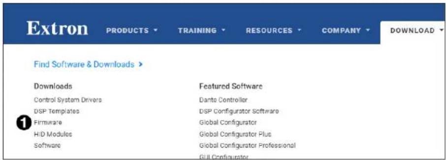
Figure 20. Firmware Link on the Download Tab
- On the Download Center page, navigate to ShareLink Pro (see figure 21, ①).

Figure 21. Firmware Download Center
- Ensure the available firmware version is a later version than the current one on the device, and click the Download link (2).
NOTE: The firmware release notes provide details about the changes between different firmware versions. The file can be downloaded from the same page as the firmware.
- Submit any required information to start the download. Note where the file is saved.
NOTE: For instructions on loading new firmware to the device, see Figure 16, ③ on page 21.
Firewall Traversal
In order for the ShareLink Pro 2000 to function correctly with the ShareLink Pro applications, it is recommended that the following firewall rules be used to allow traffic to pass. The table below details the ports and their functions.
| Port Type | Direction Function Open Notes | ||||
| 53 | UDP/TCP | Both DNS Required | This port is used for communication with a DNS server. | ||
| 67 UDP | Both DHCP Required | This port is used for communication with a DHCP server. | |||
| 68 UDP | Both DHCP Required | This port is used for communication with a DHCP server. | |||
| 80 TCP | Both | HTTP Required | This port is used to access the default web page. | ||
| 123 UDP | Both | NTP | Required | This port is used for communication with an NTP server. | |
| 161 UDP | Both | SNMP | Optional | This port is used for SNMP management. | |
| 443 | TCP | Both | HTTPS | Required This port is used for accessing the admin configuration web page. | |
| 1041 | UDP Both | GVE discovery | Optional | This port is used for discovery of ShareLink Pro devices by GVE software. | |
| 1230 | UDP | Outbound | Discovery | Required This port is used for discovery of ShareLink Pro devices by software client applications. | |
| 1231 | UDP | Inbound | Discovery | Required This port is used for discovery of ShareLink Pro devices by software client applications. | |
| 4502 | TCP | Both GVE | Optional | ||
| 4503 | TCP | Both GVE | Optional | ||
| 4522 | TCP | Both | PCS file transfer | Required This port is used for configuration. | |
| 4523 | TCP | Both | PCS config. | Required This port is used for configuration. | |
| 4534 | TCP | Both | ID messaging service | Optional This port is used for Extron Control System messaging. | |
| 5353 | UDP Both | Apple/Miracast Screen Mirroring discovery | Required This port is used by Bonjour/ Avahi network discovery for Apple Screen Mirroring discovery, as well as mDNS for Miracast device discovery. | ||
| 7000 | TCP | Both | Apple Screen Mirroring | Required This port is used for Apple Screen Mirroring. | |
| 7100 | TCP | Both | Apple Screen Mirroring | Required This port is used for Apple Screen Mirroring. | |
NOTE: mDNS/Multicast must be enabled on the network in order for Apple Screen Mirroring and Miracast to function properly.
| Port Type | Direction Function | Open Notes | ||
| 7236 TCP | Both Miracast Required | This port is used for Wi-Fi Direct control in order to establish and manage Miracast sessions between the client device and the ShareLink Pro | ||
| 7250 TCP | Both Miracast Required | This is the port on which the ShareLink Pro listens for Miracast packets when Miracast over Infrastructure is enabled. | ||
| 8554 RT | SPP Both ConferenceShare | Required | This port is used for ConferenceShare. | |
| 60000 RTP | Both ConferenceShare | Required | This port is used for ConferenceShare | |
| 1000-65384 | UDP Outbound | Video streaming | Required | These ports are used for streaming video data to the ShareLink Pro. Port is negotiated at run-time in the range 1000 to 65384 (randomly). |
| 1000-65384 | UDP Outbound | Audio streaming | Required | These ports are used for streaming audio data to the ShareLink Pro. Port is negotiated at run-time in the range 1000 to 65384 (randomly). |
| 22023 TCP | Inbound | Control | Required | This port is used for controlling the ShareLink Pro via SIS-over-SSH. |
| 29053 TCP | Both | Apple Screen Mirroring | Required This port is used for Apple Screen Mirroring |
Toolbelt
The Extron Toolbelt utility is available on the Extron website. Toolbelt is a stand-alone Windows application for the management of control systems. Toolbelt can automatically discover SharePoint Pro devices on a network (see the Toolbelt Help file). You also can manually add devices, using the known IP addresses. Once you log in to a SharePoint Pro device, you can perform tasks such as:
• View the device and system information.
• View and edit network information.
• View and set SSL certifications.
• Use utilities such as Ping, Reset, and Reboot.
- Configure 802.1X security settings.
• View 802.1X status logs.
- Update the firmware to a selected device or group of devices.
Secure Sockets Layer (SSL) Certificates
The ShareLink Pro 2000 ships with factory-installed SSL certificates created by Extron. If you want or are required to use a different SSL certificate at your installation site, then you can use PCS to change the SSL certificate at any time. The PCS Help File provides instructions on how to apply an SSL certificate.
NOTE: Some certificates require a passphrase that is created when the certificate is created. If a passphrase is required, you must enter that passphrase before uploading and applying the certificate.
IP Link Pro controllers and devices such as the ShareLink Pro 2000 support standard OpenSSL certificate encodings such as .pem (Privacy-enhanced Electronic Mail) and .der file types. PEM file types are ASCII encoded and are the required format for uploading to the ShareLink Pro 2000 receiver. DER (Distinguished Encoding Rules) file types are binary encoded and can typically have several file extension variations, such as .crt and .cer. There are many standard tools that can convert from DER to PEM file encodings if needed.
NOTE: A DER format file must be converted to PEM encoding before uploading it to the unit.
To properly create the certificate for uploading to Extron devices, ensure that the certificate file meets the following requirements:
- Contains X.509 certificate information
- Contains public and private keys
- Uses PEM encoding
NOTE: ITU-T standard X.509 covers aspects of public key encryption, digital cryptography, certificates, and validation.
Contact your IT administrator for more information on what tools and policies are required to obtain or create the SSL certificate and, if necessary, the corresponding passphrase.
Troubleshooting
The following table gives recommended actions to solve problems that may occur during setup or operation. If the problem persists after performing the recommended action, contact Extron Technical Support.
| Problem Actions | |
| (Windows only)Audio level lowers while using the Mirror Screen or Mirror Application features | Open theSoundsettings on your PC, and check the following:Check that Dolby Digital Audio is disabled in your PC's Sounds settings as follows:1. Select thePlaybacktab on theSoundssettings window.2. Right-clickSpeakers/Headphonesand clickProperties.3. Select theEnhancementstab.4. Make sure Dolby Digital Audio is disabled.In theCommunicationstab, make sure the setting for “When Windows detects communication activity” is set toDonothing. |
| (Windows only)No audio for the Mirror Screen or Mirror Application features | Make sure that the ShareLink Pro application is not muted in the PC’s volume mixer.In theRecordingtab (within the PC’sSoundssettings), make sure thatStereoMixis enabled and set as the default device.In thePlaybacktab, check thatSpeakeris enabled and set as default device.In theRecordingandPlaybacktabs, check that the ShareLink Pro Audio Driver is enabled.Download and install the ShareLink Pro 2000 software from the Extron website (seepage 12for instructions). |
| (Windows only)Extron Audio Driver has no audio support after being installed | In theRecordingandPlaybacktabs, check that the ShareLink Pro Audio Driver is enabled and set as default device when the ShareLink Pro application is running.Download and install the ShareLink Pro 2000 software from the Extron website. |
| (iOS only)The ShareLink Pro device is not listed in the Screen Mirroring list of devices | Make sure the iOS device is on the same network as the ShareLink Pro device.In PCS, go toGeneral Settings, then select theAccess/Role Setuptab and make sure IOS Airplay is enabled.Make sure the specific network ports required for Apple Screen Mirroring are open (seeFirewall Traversalon page 81 for port requirements). |
| 4K/60 is not outputting on a 4K/60 capable display | Test the connection using a shorter HDMI cable.In PCS, go toEDID Minder. In the EDID Assignment panel, make sure HDMI Pass-Through is set to 4K @ 60 Hz.In PCS, go toInput/Output Config. In the Output Configuration panel, set the Format to the appropriate color space for the display. |
| (Windows only)Mirror Screen and Mirror Application features are slow or not working | Make sure that the graphics drivers are up to date.Download and reinstall graphics drivers directly from the driver website (such as Intel®, NVIDIA® GeForce®, or AMD® RadeonTM). |
| (iOS only)The Share Website feature on the iOS app shows a blank page | Make sure the device is connected to the internet. |
| Unable to install NET 4.6.2 on a Windows 8.1 system | Install Windows update KB2919355. |
Extron Warranty

Extron warrants its powered products against defects in materials and workmanship for a period of three years from the date of invoice. In the event of malfunction during the warranty period, Extron will repair or replace a products to whatever extent it shall deem necessary to restore the product to proper operating condition.
This Limited Warranty does not apply if the fault has been caused by misuse, improper handling care, electrical or mechanical abuse, abnormal operating conditions or non-Extron authorized modification to the product. Extron Electronics makes no further warranties either expressed or implied with respect to the product and its quality, performance, merchantability, or fitness for any particular use. In no event will Extron Electronics be liable for direct, indirect, or consequential damages resulting from any defect in this product even if Extron Electronics has been advised of such damage. Please note that laws vary from state to state and country to country, and that some provisions of this warranty may not apply to you.
Powered Warranty Exception
Everlast™ Power Supplies — Extron warrants Everlast power supplies against any defects in materials and workmanship for a period of seven years from the date of invoice. In the event of a malfunction during the warranty period, Extron will repair or replace the power supply to its original operating condition. Extron engineers will examine the returned product and determine whether the Everlast Power Supply Warranty or Powered Product Warranty applies.
Speakers — Extron warrants Flat Field®, SoundField®, SpeedMount®, Column Array, and System INTEGRATOR® speakers against any defects in materials and workmanship for a period of five years from the date of invoice.
Touchscreens — Extron warrants touchscreen display and overlay components against any defects in materials and workmanship for a period of one year from the date of invoice.
Annotator 300 — Extron warrants the Annotator 300 against any defects in materials and workmanship for a period of five years from the date of invoice.
Non-Powered Warranty Exception
Cable Cubby, Hideaway Surface Access Enclosures and Retractors — Extron warrants Cable Cubby cable access enclosures, HSA Hideaway Surface Access enclosures, and Retractor cable retraction modules for a period of three years from the date of invoice.
Active Cables and Active Adapters — Extron warrants active cables and active adapter cables for a period of three years from the date of invoice.
Cable Termination Tools and Dies — Extron warrants cable termination tools for a period of three years from the date of invoice, excluding the die.
Return Information
Units must be returned insured, with shipping charges prepaid. If not insured, you assume the risk of loss or damage during shipment. Returned units must include the serial number and a description of the problem, as well as the name of the person to contact in case there are any questions.
NOTE: To assure the highest level of service, a return authorization number must be obtained from Extron before products are returned for service. Products must be shipped to Extron, prepaid along with proof of purchase only after obtaining a Return Authorization (RA) number from the Extron Customer Support department.
Please contact Extron to receive an RA (Return Authorization) number:
USA: 714.491.1500 or 800.633.9876
Asia: 65.6383.4400
Europe: 31.33.453.4040 or 800.3987.6673
Japan: 81.3.3511.7655
Africa and Middle East: 971.4.299.1800
- User Guide
- Collaboration Systems
- Safety Instructions
- Safety Instructions • English
- FCC Class A Notice
- ATTENTION:
- Battery Notice
- Conventions Used in this Guide
- Notifications
- Specifications Availability
- Contents
- Introduction......1
- Installation....4
- Operation Using a Computer....11
- Operation Using a Mobile Device....26
- Enterprise Discovery Service.... 33
- Other Configuration Options.... 39
- SIS Configuration and Control....50
- Reference Information 79
- Introduction
- About the ShareLink Pro 2000
- Features
- Rear Panel Features and Cabling
- NOTES:
- NOTE:
- Default IP settings:
- LED indicators:
- Power Notifications
- Front Panel Features and Cabling
- Using the Standby Screen
- Operation Using a Computer
- Connecting a Computer to the ShareLink Pro 2000
- Connecting through an External WAP
- Connecting through a Network Hub, Switch, or Router
- Downloading the ShareLink Pro 2000 Software
- Downloading the software from the embedded Web pages
- Downloading the software from the Extron website
- Using the ShareLink Pro 2000 Software
- Connecting to the ShareLink Pro
- Presenting Content
- Moderating a Presentation
- Using the Embedded Web Page
- NOTE: When selecting an option on the embedded web page:
- Viewing a Presentation Using WebView
- Presenting a Desktop Using WebShare
- Using the Admin Page
- Mirroring a Screen Using the WFA 100 Miracast Adapter
- About the WFA 100
- NOTE: Minimum requirements for Miracast:
- Using the WFA 100
- Screen sharing options
- Disconnecting from the display
- Operation Using a Mobile Device
- Downloading the ShareLink Pro App
- Using the ShareLink Pro App
- Connecting to a ShareLink Pro Unit
- App Menu
- Using iOS Screen Mirroring
- Discovering a ShareLink Pro Device on a Different Subnet for Apple Screen Mirroring
- Enterprise Discovery Service
- Enterprise Discovery Service - Overview
- Configuring the EDS Host "Pointer"
- EDS Workflow
- Selecting and Configuring the EDS Host
- Configuring the EDS Host in PCS
- Click OK:
- Configuring EDS Clients in PCS
- Enabling EDS in Client Devices
- Managing Login Code Settings for EDS Clients
- Other Configuration Options
- Device Discovery using ShareNext™
- Using ShareNext with the ShareLink Pro Software and Mobile App
- Using ShareNext with Apple Screen Mirroring
- Digital Signage Feature
- NOTE: This feature is available only with a LinkLicense.
- Select one of the following options:
- Click Assign. The assigned web URL is shown on the Standby Source panel (①):
- Miracast Connection Using the WFA 100
- Miracast Overview
- Miracast Connection Methods
- Option 1
- Option 2
- Option 3
- Configuring the WFA 100 Channel
- Miracast Troubleshooting
- Supported platforms
- Network ports
- Miracast Graphics Support
- Miracast Wi-Fi Direct Support
- SIS Configuration and Control
- Host Device Connection
- SIS Overview
- Host and Device Communication
- Error Responses
- Command and Response Tables Overview
- Symbol Definitions
- KEY:
- SIS-over-SSH
- Expo and Streaming
- Reference Information
- Mounting
- Tabletop Mounting
- Furniture Mounting
- Rack Mounting
- UL Guidelines for Rack Mounting
- Rack Mounting Procedure
- Firmware Download
- Firewall Traversal
- Toolbelt
- Secure Sockets Layer (SSL) Certificates
- Troubleshooting
- Extron Warranty
- Powered Warranty Exception
- Non-Powered Warranty Exception
- Return Information
Brand : Extron
Model : ShareLink Pro 2000
Category : Wireless Content Sharing