
K-8423A-0 - Toilets KOHLER - Free user manual and instructions
Find the device manual for free K-8423A-0 KOHLER in PDF.


| Product Type | Wall-Faced Intelligent Toilet |
| Model | K-8423A-0 |
| Brand | Kohler |
| Overall Dimensions (W x D x H) | 675 mm x 438 mm x 533 mm |
| Weight (excluding in-wall tank) | Approx. 48.5 kg |
| Power Supply | 220-240V AC, 50Hz, 10A dedicated circuit with GFCI/RCD |
| Rated Power | 1000W |
| Max Instantaneous Power | 1600W |
| Flush Volume | 4.5L (full) / 3L (eco) |
| Water Supply Pressure (dynamic recommended) | 70 kPa (min) - 740 kPa (max static) |
| Water Supply Connection | Bidet water supply and Dual Check Valve included |
| Ambient Temperature Range | 1°C to 40°C |
| Functions | Hands-free flushing, manual dual-flush, bidet washing, blow-dry, deodorizer, night light, UV sterilization, heated seat, remote control |
| Seat Material | Antibacterial resin |
| Waste Connection | S-trap or P-trap (DN80 connector) |
| Safety Features | GFCI/RCD protection, grounding required, backflow prevention |
| Maintenance | Clean seat and nozzle weekly; clean filter periodically; do not use corrosive cleaners |
| Included Components | Pan with faceplate, remote assembly, Hydro-Tower 500 in-wall tank, faceplate |
| WaterMark Certification | ATS 5200.051 |
| WELS Rating | 4-star (when auto-flush is off) |
Frequently Asked Questions - K-8423A-0 KOHLER
User questions about K-8423A-0 KOHLER
0 question about this device. Answer the ones you know or ask your own.
Ask a new question about this device
Download the instructions for your Toilets in PDF format for free! Find your manual K-8423A-0 - KOHLER and take your electronic device back in hand. On this page are published all the documents necessary for the use of your device. K-8423A-0 by KOHLER.
USER MANUAL K-8423A-0 KOHLER
- We appreciate your commitment to Kohler quality. Please take a few minutes before you begin installation to review this manual to become familiar with tools, materials and installation methods. If you encounter any installation or performance problems, please don't hesitate to contact us. Thanks again for choosing Kohler Co.
- Please follow instructions closely to avoid costly mistakes caused by improper installation. Cover and protect the components and fittings at all times during installation. Flush the plumbing lines before initial use.
- All information in this manual is based upon the latest product information available at the time of publication. Kohler Co. reserves the rights to make changes in product characteristics, packaging or availability at any time without notice.
- Before continuing, please ensure there is no existing damage to the toilet and that there is suitable space for installation with no interference with other bathroom fixtures such as shower door openings. Before proceeding with installation, ensure there is ample room (approx 600mm) down each side of the pan to allow for servicing.
- To prevent serious damage, do not use corrosive solutions (see back page for care and cleaning information). Any use of non-recommended products could void the Kohler warranty.
- This manual includes important care and cleaning information - please save these instructions.
COMPLIANCE: Ensure installation adheres to local building code & applicable plumbing/electrical standards.
- The Kohler Veil Intelligent Toilet - Wall Faced (K-8423A-0) is WaterMark certified according to ATS 5200.051 Technical Specification for Plumbing and Drainage Products - Bidet Douche Seats.
- Installation must comply with AS/NZS 3500.1 Plumbing and Drainage - Water Services and AS/NZS 6400 Water Efficient Products - Rating and Labelling.
Backflow Prevention
- The supplied Dual Check Valve is WaterMark certified according to AS 2845.1 Water Supply - Backflow Prevention Devices - Materials, Design and Performance Requirements.
• Each site must have High Hazard Backflow Prevention installed upstream of the installation. - For domestic installations, consult with a Licensed Practitioner (Plumber) before installation.
- For commercial applications, refer to a Hydraulic Consultant before specification or installation.

WARNING: Risk of electric shock. Disconnect power before servicing.

WARNING: Risk of electric shock. Connect only to a properly-grounded, grounding-type receptacle which is tested by a Ground-Fault Circuit-Interrupter (GFCI) or Residual Current Device (RCD)

WARNING: Risk of electric shock. This product must be grounded. Connect only to a dedicated 220\~240V AC, 60Hz circuit protected with grounded circuit-breaker or grounded electric leak circuit breaker

WARNING: 10A power supply is required.
Product Functions
- Hands-free flushing
- Manual dual-flush option
- Backflow prevention
• Pre-set water inlet level & flush volume
- Suitable for either S-trap or P-trap installations
Advantages for the In-wall Water Tank
- Anti-impact, rust-proof, macromolecule water tank reduces the possibility of leakages.
- Advanced water tank system is able to adjust 4.5/3 litre water discharge. To maintain the 4-star WELS rating, switch off the Auto-flush option.
- No influence on wall structure, superb sound-proof effectiveness.
- Easy and quick installation saves time and labour.
- Easy servicing, wall reconstruction is not required.
• Sanitary system with no residual waste. - Super thin tank body saves installation space and is applicable for all thin mounting walls.
The concept of in-wall tank design & installation
- Compared to traditional setups, the in-wall tank provides an easier and faster installation method, which gives a more artistic and complete finish.
- The greatest advantage of the in-wall tank is that the toilet installation is not limited to certain locations. It can be hung almost anywhere which affords a far greater use of bathroom space.
Component information
- Pan with faceplate ...... 20313A-0
- Remote assembly ...... 1235953
• Hydro-Tower 500 in-wall tank .. 18647A-NA
- Faceplate 1268687
Required tools and materials
• 19mm spanner or adjustable wrench
- Blade
- File
- Hacksaw
- Hex key
- Impact drill
- Level
- Screwdriver
- Rulers/measuring tape
• Electrical tape + thread sealing tape
- Plug for bidet water supply
- Screws/bolts to affix in-wall tank to wall frame and bottom plate (not supplied). Recommended to use M6x40 coach screws with appropriate washers.
Dimension Drawing
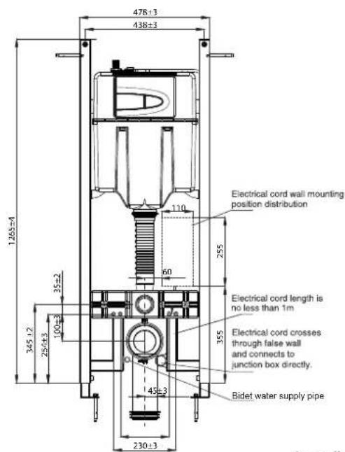
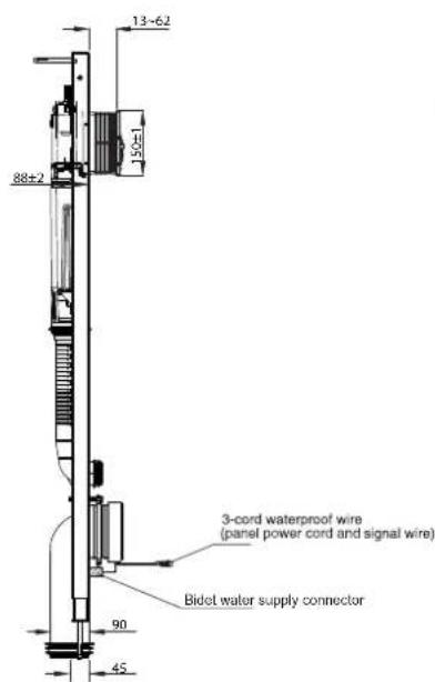
1mm - 2.5mm hard cord should be reserved as power input during the wall construction. In the circuit, a 220V, 50Hz, 10A minimum Ground-Fault Circuit Interrupter (GFCI) or Earth Leakage Circuit-Breaker (ELCB) is required. For detailed positioning of the hard cord, see diagram below.
natural_image
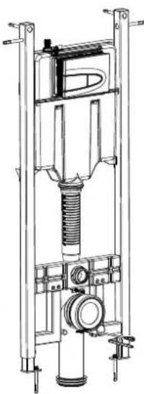
Technical line drawing of a mechanical lifting device with no visible text or symbolsIn-wall tank dimension drawing
Fig #1
Kohler reserves the right to change marked dimensions without prior notice.
NOTE: S-trap installation shown as default. P-trap configuration is achievable by using a DN80 waste pipe connector.
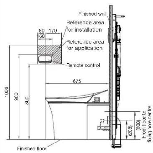
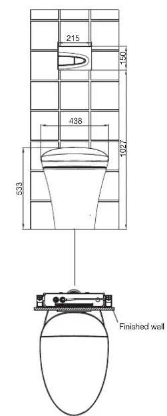
Toilet dimension drawing
Fig.#2
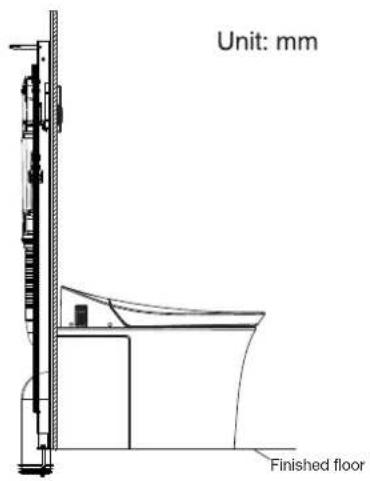
Kohler reserves the right to change marked dimensions without prior notice.
SPECIFICATION(8423A-0)
| The amount of flush | 4.5L/3L |
| Min water supply (recommend) | 70kPa (Dynamic pressure) |
| Max water supply | 740kPa (Static pressure) |
| Specification | 220V~, 50Hz |
| Rated power | 1000W |
| Max. instant power | 1600W |
| Product overall dimension | 675mm x 438mm x 533mm (Height shall be calculated from floor to the top of the product) |
| Product weight (exclude in-wall tank) | About 48.5Kg. |
| Ambient temp | 1- 40 °C |
Note: Refer to the User Guide for intelligent bidet specification.
Overall Diagram
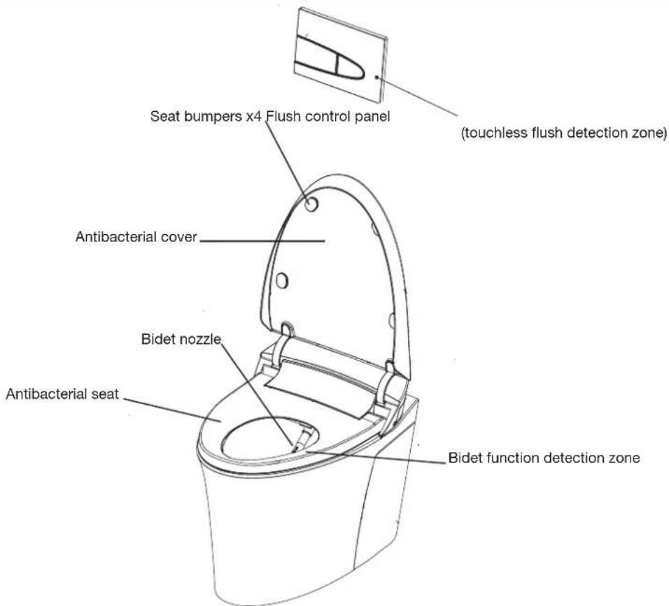
Fig.#3
Before Installation
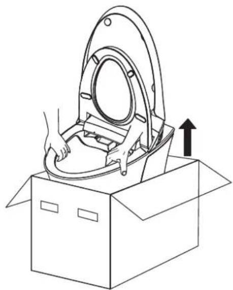
A. Hold the edge of toilet bowl and slide out from packaging box.
WARNING: Risk of product damage or personal injury. When lifting up the toilet, please hold it by the rim. Product is heavy, please employ a two-person lift.
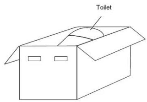
Fig.#4
natural_image
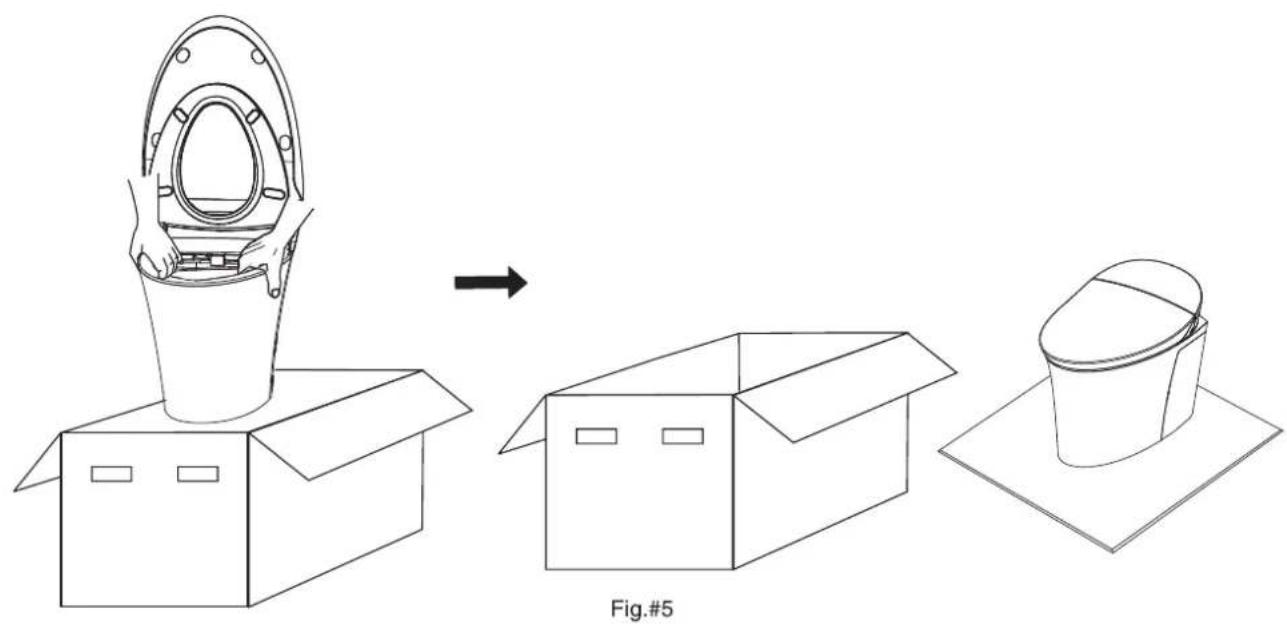
Line drawing of a hand placing a circular component into an open cardboard box with an upward arrow (no text or symbols)B. Place an 800mmX800mm soft protective material on the floor, slide toilet out from the packing box and sit on protective material.
natural_image
Line drawing showing a container being placed into a box, then moving to a cup on a tray (no text or symbols)Installation
A. Where applicable, remove the old toilet
B. Warning for installation

WARNING: Risk of electric shock. Disconnect power before servicing.
Note: The power supply and water pipe of this product is designed for wall face style. Installation method is marked in dimension drawing.

WARNING: Risk of electric shock. For plug-in installation/wall-mounted electrical supply: Connect only to a properly-grounded, grounding-type circuit which is protected by a Ground-Fault Circuit-Interrupter (GFCI) or Earth Leakage Circuit Breaker (ELCB).

WARNING: Bathtub and sprinkler head shall be far away from electrical parts (e.g. remote controller, power receptacle etc.) if it is wall-hung style, water proof or splash proof receptacle is required. If wall-mounting power supply is adopted, require anti-water and anti-splash power receptacle.
C. In-Wall tank installation
- Remove the in-wall tank from packing box. Remove paper board from cistern access opening. Then remove the support paper board under the motor assembly.
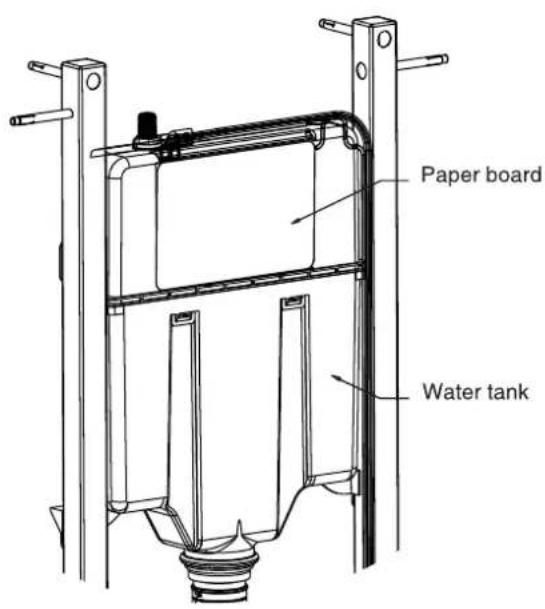
Fig.#6
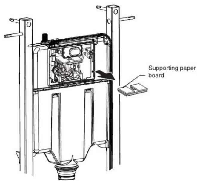
- Adjust the supporting feet height by loosening the bolts with hex key. Slide the feet up or down to attain the ideal measurement of 308mm from the floor to the centre of the bowl fixing holes. The frame should be installed on top of the bottom plate (usually 45mm high). Please allow for this height when adjusting the feet. Ensure the adjustment is even by using a level, and tighten the bolts to set the height.
IMPORTANT: Protect electronic connection point and wires from accidental damage.
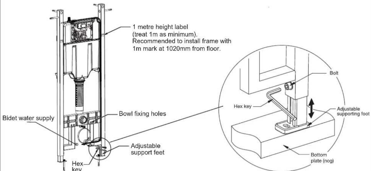
Fig.#7
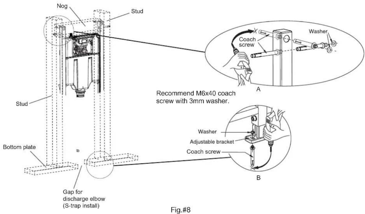
- Construct a mounting frame to surround the in-wall tank. This should consist of vertical studs and a horizontal nog, adjacent to the steel supports. If installation is an S-trap configuration, ensure the bottom plate has at least a 100mm cut-out in the centre for the discharge elbow.
If required, drill pilot holes with a drill as shown in Fig A and B.
Insert coach screws with washers into the installation holes in the framework, then tighten.
Repeat for all screws.
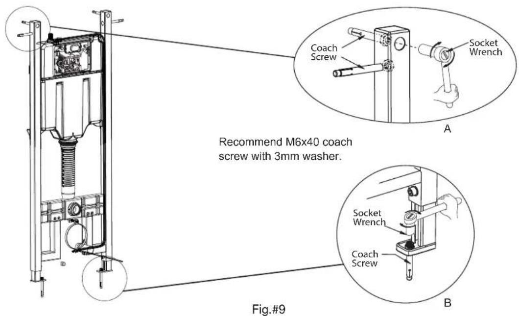
- Tighten screw by wrench as shown in Fig A. Tighten screw by wrench as shown in Fig B.
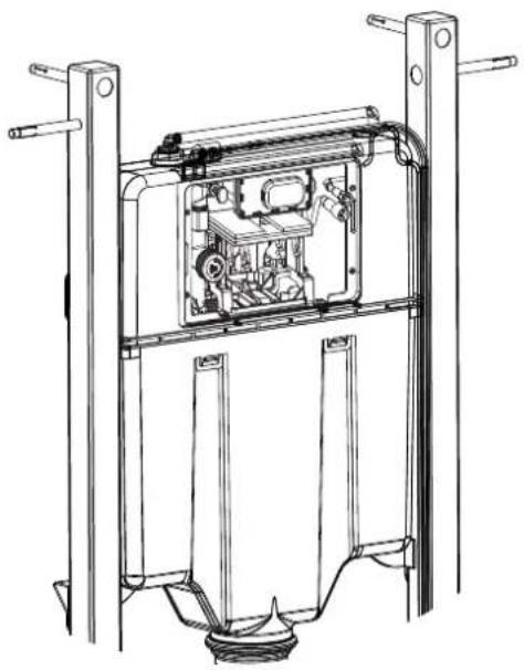
- Ensure water tank internal valve is OFF.
- Connect a temporary rubber or plastic hose onto valve and flush the water supply line. Ensure water is clean with no residual debris fouling the inside of the pipeline.
natural_image
Technical line drawing of a mechanical lifting device with internal components and mounting brackets (no text or symbols)Fig.#10
- Place square cover within protection cover of water tank. Snap the buckle into the slot and tighten square cover bolts on tank.
NOTE: Square cover has the word TOP on it indicating which surface should face upwards when installed.
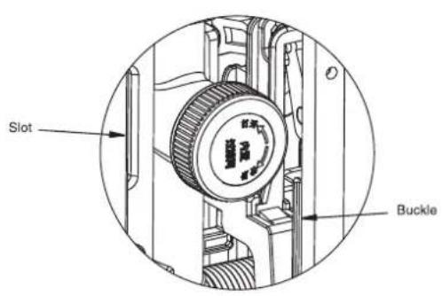
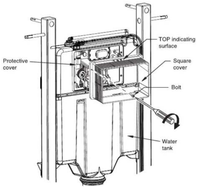
Fig.#11
D1. S-trap installation method
(skip to Step D2 on pg10 for P-trap installation)
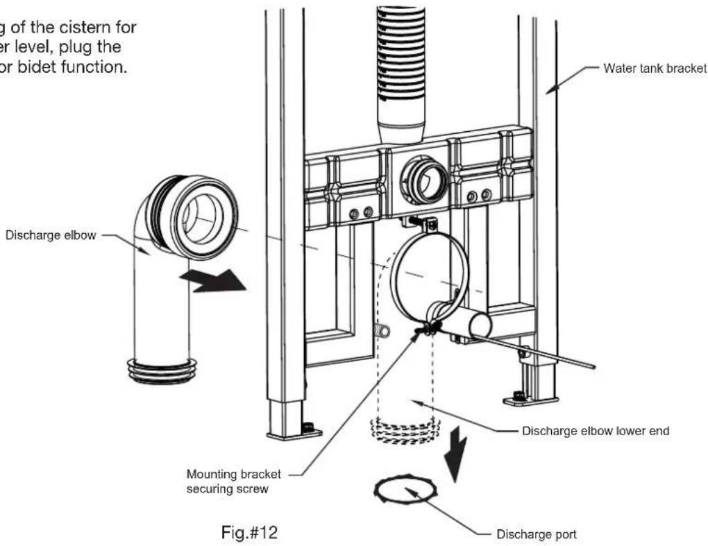
- Loosen the screw on mounting bracket, then insert discharge elbow into the mounting bracket. Adjust the pipe position and tighten the mounting bracket screw to secure the discharge elbow. Lastly, insert the discharge elbow lower end into discharge port.
Note: To allow testing of the cistern for leaks and water level, plug the water supply for bidet function.
- Place the bung into the discharge elbow.
Note: Do not lubricate the connection between pan and waste connector. Lubricate connection between waste connector and discharge elbow.
Proceed to Step E on pg10.
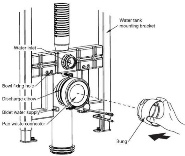
Fig.#13
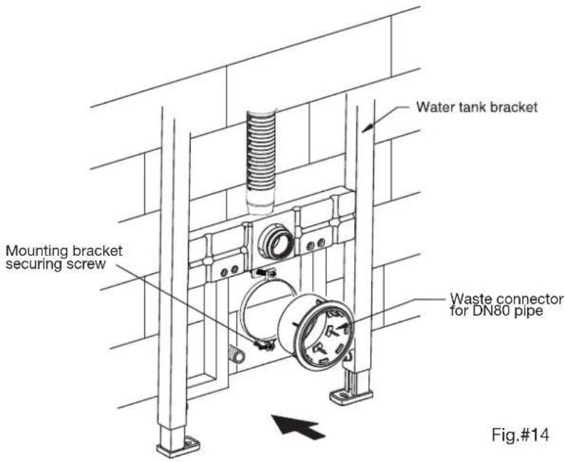
D2. P-trap installation method
(refer to Step D1 on pg9 for S-trap installation)
- Loosen screw on mounting bracket and insert the waste connector. Adjust waste connector position and tighten the mounting bracket to secure.
E. Prepare and finish the wall
IMPORTANT: 1. When preparing the wall, the wallboard/tiling cut-out must fit very neatly around the square cover of flush panel. No large gaps are permitted (tolerance of approx 1mm).
2. There may be significant amounts of dust when preparing the wall - be sure to fit dust cover over cistern opening and protect the electrical fittings and pipework.
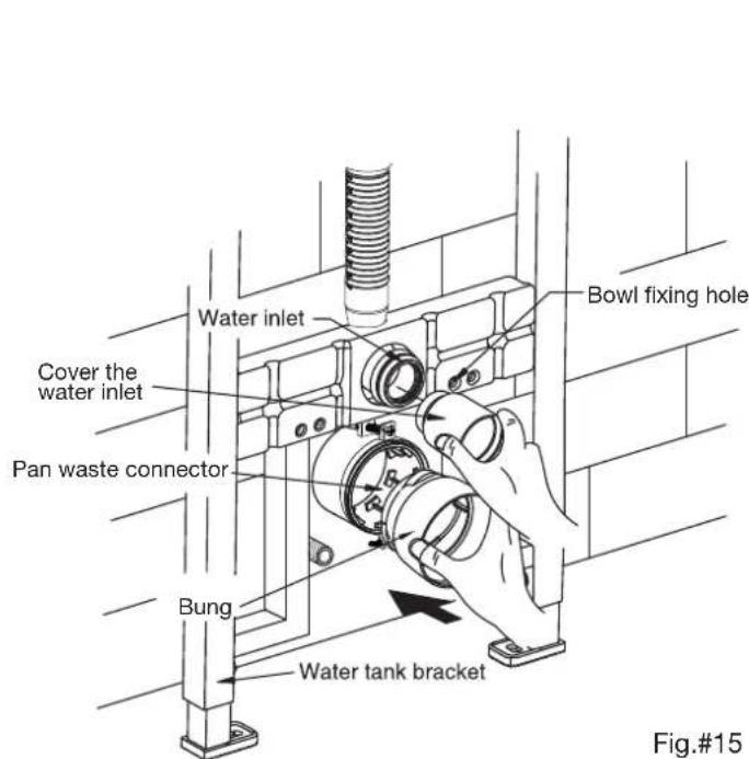
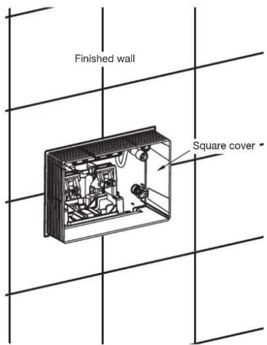
- Remove the bung from discharge port after finishing the wall preparation, then cut off the excess of square cover and concealed conduit with a blade.
- Insert the pan fixing bolts so the washer is hard against the finished wall, notched end outwards for tightening.
NOTE: 1. Ensure the bolt can rotate freely when preparing the wall. The washer should be located outside the wall.
2. When preparing the wall, cross the water inlet hose, control panel signal wire and power cord through the wall and under the tank.
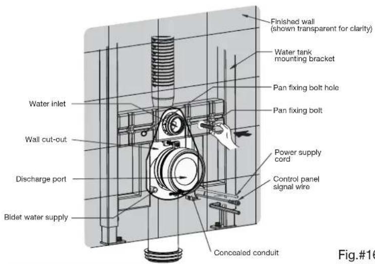
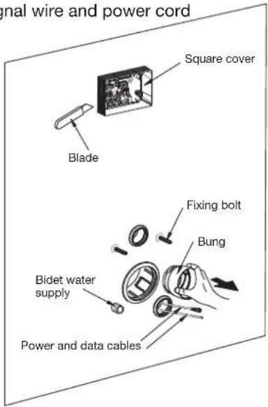
Fig.#16
F. Bowl installation
- Remove the side panels.
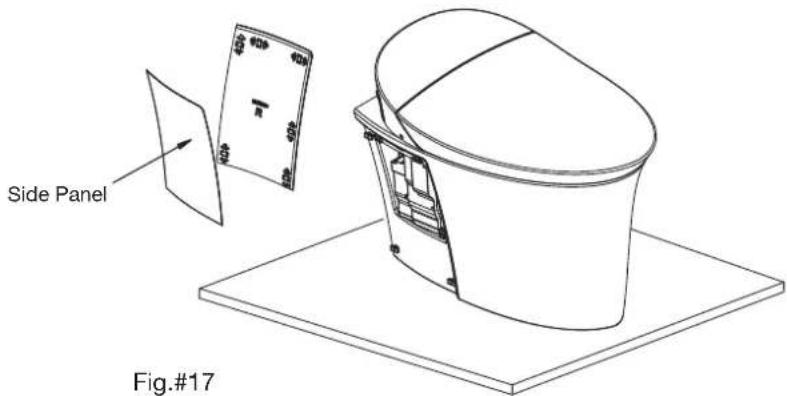
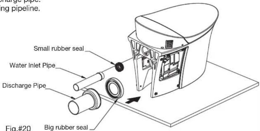
- Install the discharge pipe and water inlet pipe as shown. Place a ruler on the rear of the discharge pipe and water inlet, and use a pencil to mark the position. Adjust the space based on the rear of the toilet to wall discharge port.
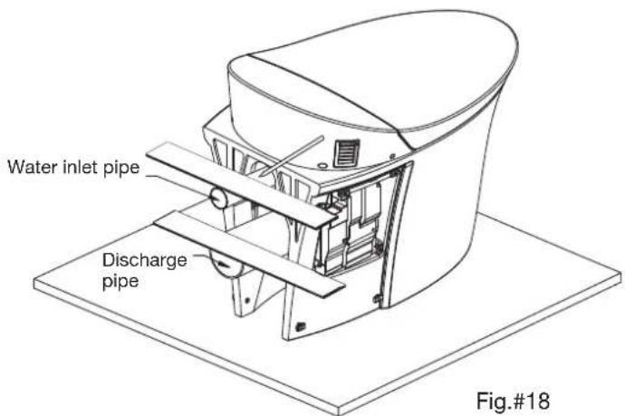
- Mark the reserved space on the rear end of the discharge and water inlet pipes. Cut off the excess and use a file to clean up the edges.
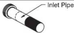
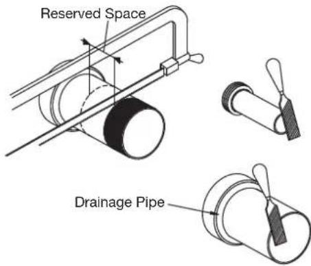
Fig.#19
- Place the small rubber seal on the water inlet pipe. Place the big rubber seal on the discharge pipe. Insert the pipes into the corresponding pipeline.
- Connect bidet water supply hose (straight end onto the water supply fitting on tank frame). Feed hose under the pan connector (discharge pipe) and attach the MF fitting onto the 90° bend. Attach this end to the pan inlet.
Ensure the pan fixing bolts are tight against the wall, as shown. Apply grease to the discharge port to ease installation.

CAUTION: Toilet is heavy, use a two person lift.
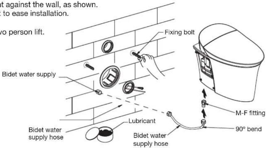
Fig.#21
- Place lag washer, rubber bush, washer onto the lag bolts, as shown. Thread on the hex nuts and tighten with a 19mm spanner or wrench. Place a level across the rim to ensure the toilet is flat.

Fig.#22
- Remove the two screws on the right-hand side of the toilet and remove the side panel. Remove the 3 remaining screws and remove the junction box cover.
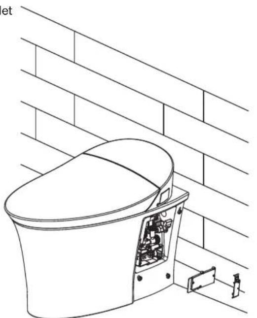
natural_image
Technical line drawing of a toilet with internal components, mounted on a brick wall (no text or symbols)Fig.#23
- Feed the power cord through the rubber gasket from the wall and connect to the junction box. Note: Wiring order shall be L, N, Ground from top to bottom.
L - Live wire N - Neutral wire Grounding wire
Power switch is OFF Green light OFF ____
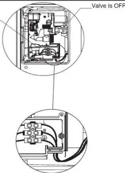
Fig.#24
- After completing the wiring work, adjust power input and lock the junction box cover.
- Ensure the in-wall tank water outlet hose connection is tightened and does not leak.
- Turn power switch to ON and open water inlet valve.
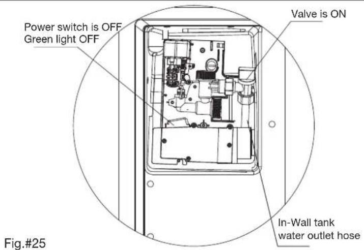
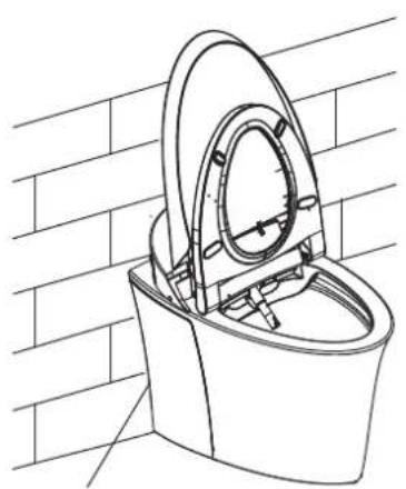
- Apply silicone sealant around the back edge of the pan to ensure a clean adhesion to the wall. Install the left and right side panels.
natural_image
Line drawing of a toilet with lid and vent, mounted on a brick wall (no text or symbols)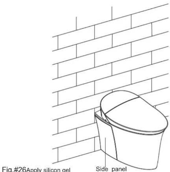
Fig.#26Apply silicon gel
G. Water Level adjustment
- Follow the steps 6 to 11 on page 19 and 20 of this document to remove the water inlet valve.
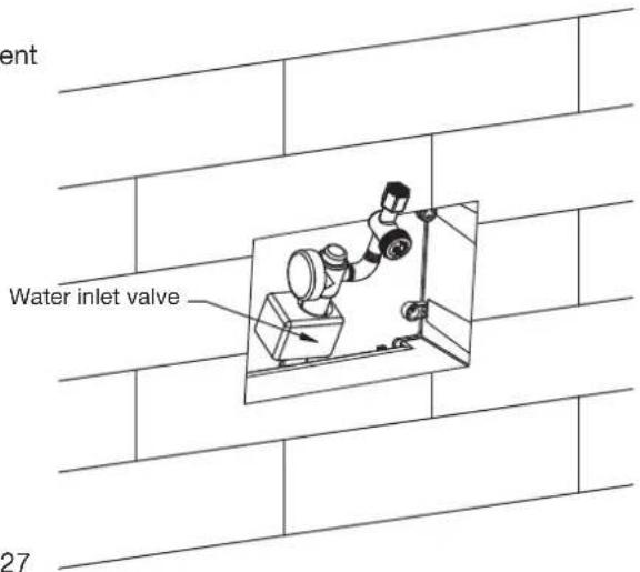
Fig.#27
- Turn the screw clockwise to increase the water level by +5mm. Place the water inlet vavle in its original position.
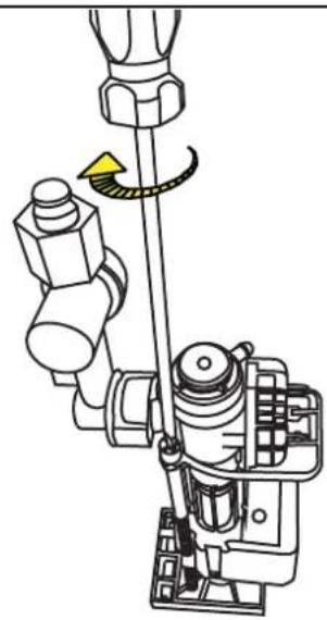
natural_image
Mechanical assembly diagram showing a rotating shaft and housing components (no text or labels)Fig.#28
H. Control panel installation
- Slide water splash plate into Slot A and B in square cover.
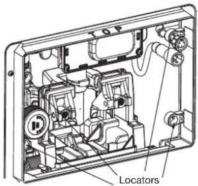
NOTE: After the splash plate is installed, the locators should be under the surface.
Snap in position
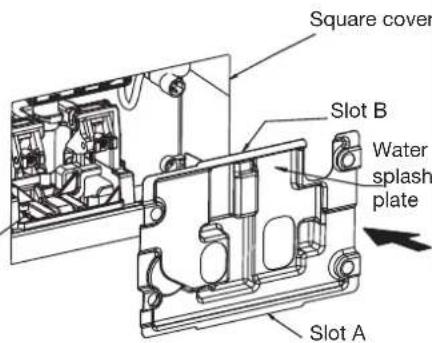
Fig.#29
I. Top Button installation
- When locating the four locknuts on supporting board, adjust to OPEN mark, as shown.
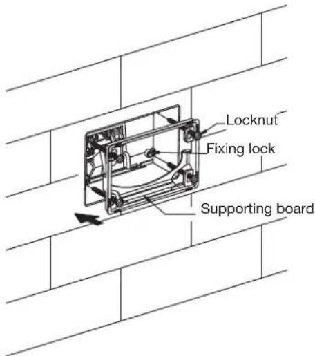
Fig.#30
- Tighten the four screws to LOCK mark after installing the supporting board.
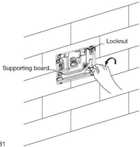
Fig.#31
- Screw two lag bolts into the bracket, as shown. Ensure the bolts are perpendicular to the wall.
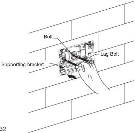
Fig.#32
- Align control panel in position, the push forward and fasten. Install motor assembly signal wire and control panel signal Wire into U type hole of splash plate, as shown below.
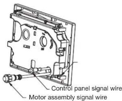
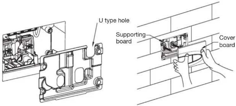
Fig.#33
- Once connected to the power and water supply, the toilet is ready for use.
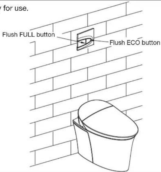
Fig.#34
Dismantle and service discharge valve
- Dismantle the control panel, as shown.
Hold control panel bottom with both hands and push upward to open the panel. Ope from the bottom up. Dismantle motor assembly signal wire and control panel signal wire.
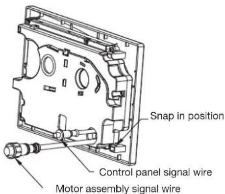
Fig.#35
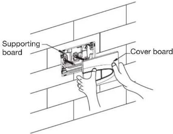
- Unscrew two lag bolts as shown
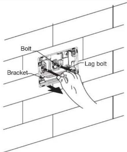
Fig.#36
- Pay special attention when dismantling supporting board.
All 4 lock nuts should align with the OPEN mark.
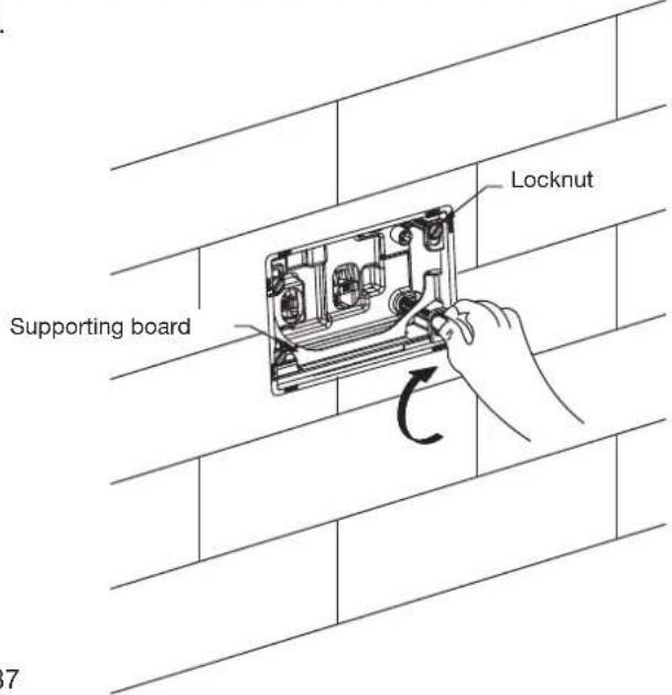
Fig.#37
- Dismantle supporting board as shown.
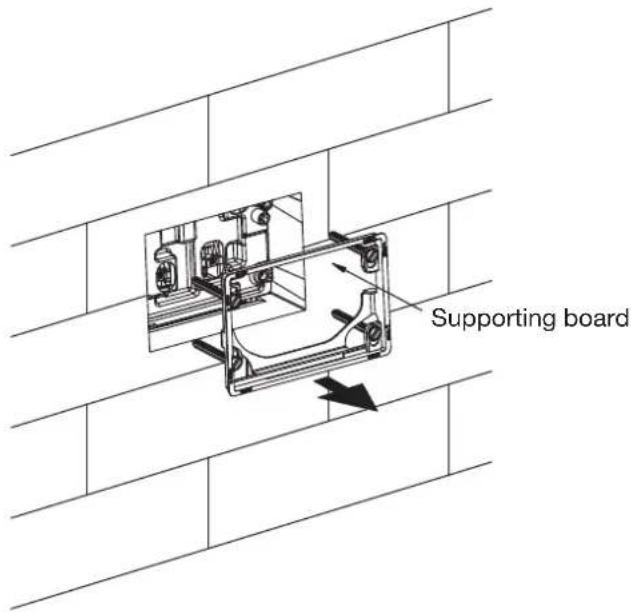
Fig.#38
- Pull water splash plate out
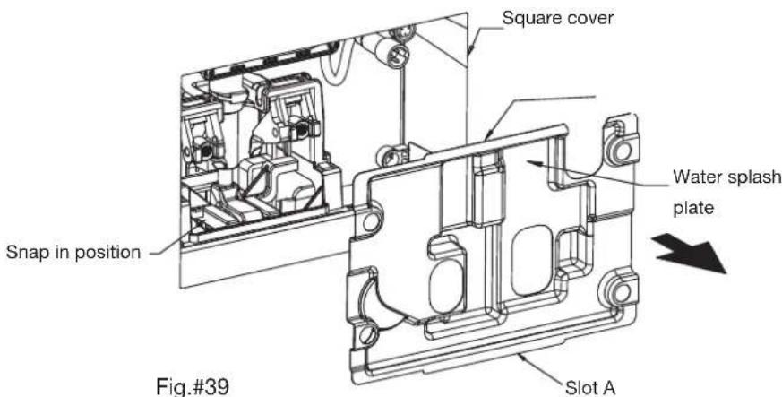
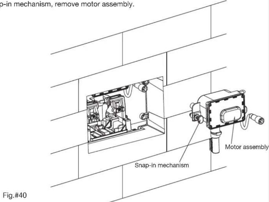
- Dismantle motor assembly snap-in mechanism, remove motor assembly.
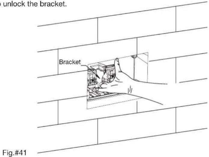
- Hold bracket top by hand as shown, then lift up to unlock the bracket.
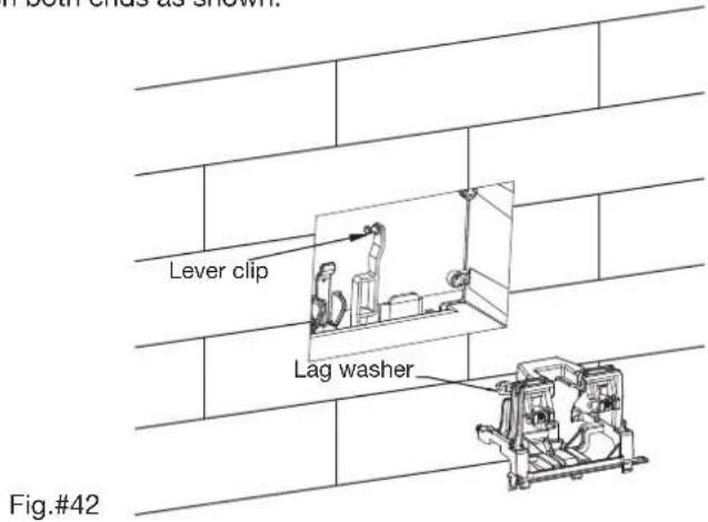
- Take discharge valve lever out from lag washers on both ends as shown.
9. Open/close water supply.
Rotate valve switch to open/close water supply as shown.
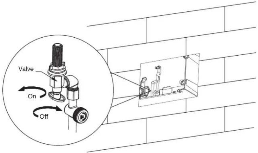
Fig.#43
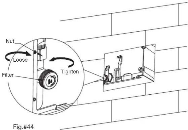
10. Loosen filter nut, as shown.
11. Remove the water inlet valve for cleaning or adjusting.
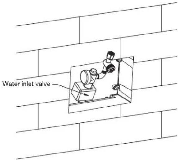
Fig.#45
12. Hold fastener by hand as shown, pull the top of fastener along with the direction of arrow. Then remove fastener.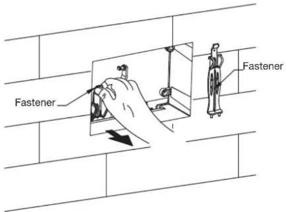 Fig.#46 Fig.#46 |
13. To remove the discharge valve, rotate valve along the arrow direction, as shown. It should make a “click” sound when installing or removing.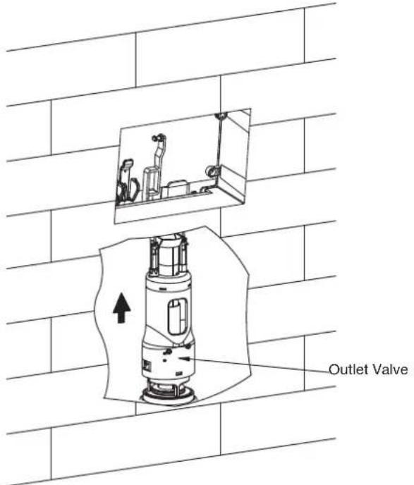 Fig.#47 Fig.#47 |
14. Loosen discharge valve as shown and then take valve out for cleaning or adjusting.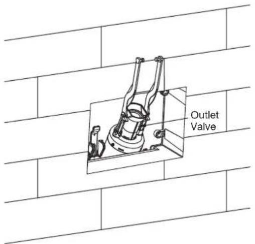 Fig.#48 Fig.#48 |
I. Clean Filter
Loosen filter locknut, as shown. Clean filter dirt with water and tighten locknut back in original position.
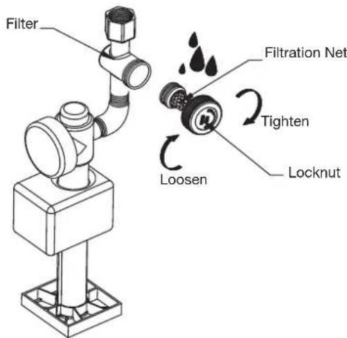
Fig.#49
J. Discharge valve adjustment
Adjust water tank flush volumes as shown:
Full Flush: 1. Open adjustment switch
2. Open small hole
Half Flush: 1. Adjust float box position (water level should be on the bottom of float box)
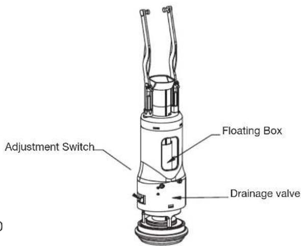
Fig.#50
K. Water inlet valve adjustment
Adjusting the control pole will cause the water level to change within the water tank. Turn the pole clockwise to increase the water level and anti-clockwise to reduce it.
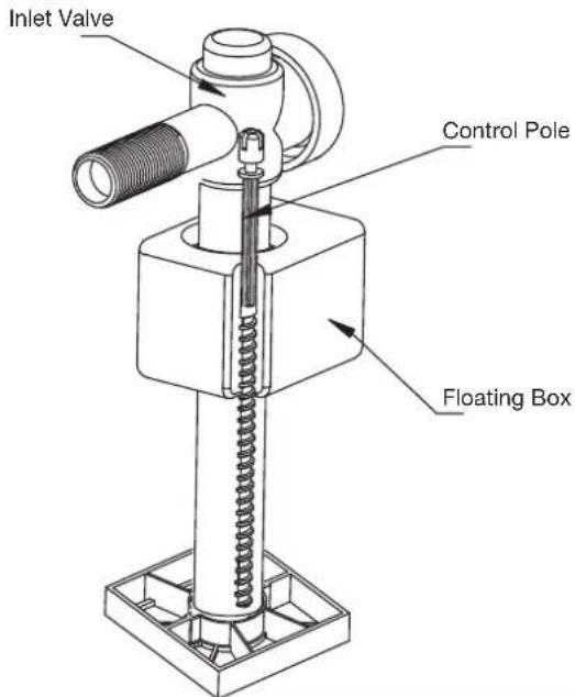
Fig.#51
Install Remote Control Docking Station
NOTE: Use suitable mounting methods for the wall construction material. Special fixings may be required for walls made of plasterboard.
NOTE: Do not install this appliance in positions where it might come in contact with water.
- Select a proper position for the control docking station to be installed. The position shall be easily operated by the user when seated on the toilet.
- Based on the docking station hole positions, drill two 6mm diameter holes, 45mm deep.
- Insert lag bolt anchors into the holes.
- Remove the double-sided tape and place docking station over the fixing holes.
- Fasten docking station with screws and place bushing on the bolts.
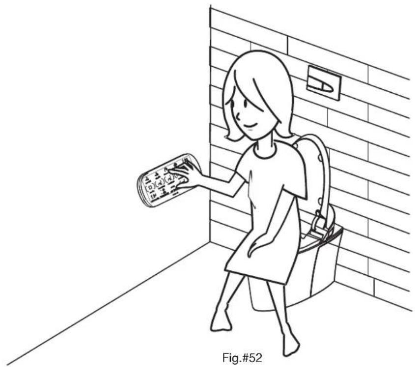
natural_image
Line drawing of a girl sitting in a bathroom near a brick wall, holding a book (no text or symbols visible)Steps of installation
Public anti-loss installation
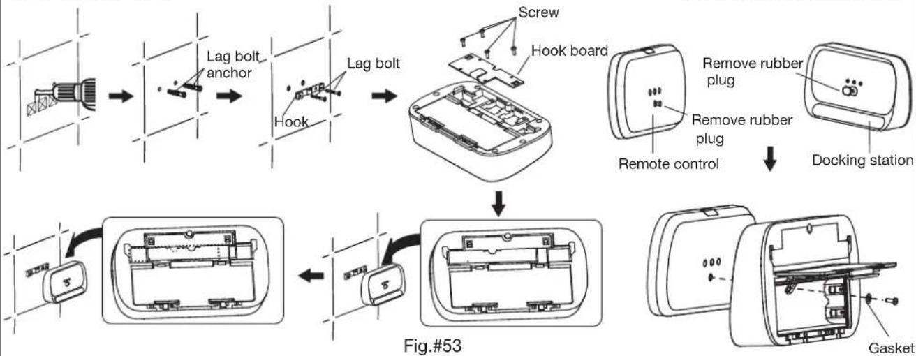
flowchart
graph TD
    A["Lag bolt anchor"] --> B["Hook"]
    B --> C["Lag bolt"]
    C --> D["Screw"]
    D --> E["Hook board"]
    E --> F["Remote control"]
    F --> G["Remove rubber plug"]
    G --> H["Docking station"]
    I["Figure #53"] --> J["Internal component with 5s mark"]
    J --> K["Gasket"]
| TROUBLE SHOOTING | ||
| This troubleshooting guide is for general aid only. A Kohler Authorised Service Representative should correct any electrical problems. For warranty service, contact your dealer or wholesale distributor. | ||
| Symptoms | Probable Causes | Recommended Action |
| 1. Toilet does not work. | A. A power failure occurred.B. Product is under protected status.C. Toilet is OFF. | A. Wait until the power is restored.B. Turn power off at switchbox and then turn back on.C. Turn on switch on terminal box. |
| 2. Toilet does not flush. | A. No water supply.B. The water supply stop is closed.C. A power failure occurred.D. Product is under protected status. | A. Wait for restoration of water supply.B. Open the water supply stop.C. Wait until the power is restored or check “manual flush” section.D. Turn on switch on terminal box. |
| 3. Toilet does not flush completely. | A. Filter screen is clogged.B. Insufficient manual button travel. | A. Refer to “Clean filter screen” sectionB. Dismantle water outlet control panel, adjust manual flush adjustment rod. |
| 4. Clean function does not operate properly. | A. No water supply.B. Water supply valve is not fully open.C. Toilet is on OFF mode.D. Unseated or current sitting position is unable to detect.E. Filter screen is clogged.F. Insufficient water supply pressure. bending. Adjust hose if required. | A. Wait for restoration of water supply.B. Fully open water supply valve.C. Turn on switch on terminal boxD. Sit again or adjust sitting position.E. Refer to “Clean and Replace Filter Screen” section.F. Inspect water inlet hose for any sharp |
| 5. Flush function stops during operation. | A. Auto stops flush function after continuous 5 min flushing.B. The seat does not detect any user. | A. If needed, press flush button again.B. Adjust sitting position and sit again. |
| 6. Spray function starts even when unseated. | A. The seat is covered by an object or the seat is wet. | A. Remove object and wipe the seat. |
| 7. Dryer stops working during operation. | A. Dryer auto stops after continuous 4 min.B. The seat does not detect any user. | A. If needed, press dryer button again.B. Adjust sitting position and sit on again. |
| 8. Deodoriser fan stops working | A. The seat sensor is not detecting the user.B. Accidental pressing of STOP button.C. Auto deodorising function is disabled. | A. Remove object or wipe seat.B. If needed, sit on again after 2 seconds.C. Refer to “Remote setting guide” section. |
| 9. Unable to open or close cover. | A. The seat sensor is not detecting the user.B. Customer interference during previous cover swing process. | A. Remove object or wipe seat.B. Use the remote or manually open/close cover back to normal position.*Do not block switch during swing process* |
| 10. Unable to auto open/close cover. | A. User does not enter/leave detecting zone.B. Remote “auto swing” function is OFF.C. Toilet is flushing. | A. Enter or leave detecting zone.B. Refer to “Remote setting guide” section.C. Wait until toilet flush process completes. |
| 11. Night light is not | A. Night light function is OFF. | A. Refer to “Auxiliary side panel function” |
| TROUBLE SHOOTING (continued) | ||
| This troubleshooting guide is for general aid only. A Kohler Authorised Service Representative should correct any electrical problems. For warranty service, contact your dealer or wholesale distributor. | ||
| Symptoms | Probable Causes | Recommended Action |
| 12. UV sterilisation stops. | A. Customer sits on seat.B. The seat is wet or covered by an object. | A. Please close cover and reactivate UV sterilisation and close toilet cover.B. Remove objects or wipe seat. |
| 13. No display on remote. | A. Battery runs out.B. Wrong battery installation.C. Remote has not been awakened yet. | A. Install new battery.B. Re-install battery correctly.C. Touch remote screen.Approach or sit on toilet.Press awaken button on remote. |
| 14. Remote unable to control toilet. | A. Battery runs out.B. Remote to toilet distance is too far.C. Toilet power is not ON.D. Toilet is under OFF mode.E. Toilet and remote are not connected. | A. Refer to “Remote battery use and replace” section to replace battery.B. Refer to “Remote - toilet communication” section and move remote closer to toilet.C. Connect toilet power supply.D. Turn on switch to terminal box.E. Refer to “Remote - toilet communication” section, connect toilet to remote. |
| 15. Seat temp is low when seated. | A. Seat temp is OFF.B. Energy saving mode. | A. Refer to “Remote guide” section for temperature settings.B. Refer to “Remote guide” section to exit energy saving mode. |
| 16. No water supply from inlet valve. | A. Water inlet valve is not OPEN.B. Water inlet float is covered by other parts.C. Water inlet valve float blocked by debris. | A. Open water inlet valve.B. Adjust other parts to avoid anycontact with float during operation.C. Clean float with water. |
| 17. No water when pressing FLUSH FULL or FLUSH ECO button. | A. Wrong adjusting board and screw rod installation.B. Discharge valve lever and barb are not connected. and snap in. | A. Re-install screw rod.B. Re-install barb on discharge valve lever |
| 18. Water level is high or too low. | A. Water inlet valve float is not set properly. | A. Adjust water level again. |
| 19. Toilet leaks. | A. Foreign objects are blocking water inlet valve float when water enters the tank.B. Foreign objects on water sealing piece. | A. Adjust other parts to avoid any contact float during process.B. Remove foreign objects on water sealing piece. |
 NOTE: To service the toilet, please observe the following rules:Turn off switch on terminal box.If necessary, open the water supply valve.Please cut off power supply before servicing terminal box. NOTE: To service the toilet, please observe the following rules:Turn off switch on terminal box.If necessary, open the water supply valve.Please cut off power supply before servicing terminal box. | ||
Customer Obligations
If you live where the water quality is hard, you must keep your discharge hole clean to ensure proper toilet operation.
Clean your toilet at least once a week, and use a long handle brush to clean discharge hole. Insert the brush in as much as possibly to prevent mineral matter accumulation.
Most toilet cleaners are not harmful to eh vitreous china surface of the toilet pan. Kohler Co. does not recommend the use of any cleaning products which are submerged in the cistern as the acids contained within the cleaner will prematurely deteriorate gaskets and valve parts. Please follow the pan cleaner manufacturer's instructions carefully.
Please follow manufacturer instructions when using toilet cleaning products. Do not use harsh abrasive cleaners. Do not use corrosive detergents or solutions on or near the seat.

WARNING: Any damage caused by chlorine (Lime Hypochlorite) shall void the KOHLER warranty.

WARNING: Do not use cement to install toilet. The cement thermal expansion may cause toilet feet to be damaged and/or burst. KOHLER will not be responsible for any toilet damage caused by unsuitable installation products or methods.

WARNING: Prevent toilet damage. Do not toss unusual products into toilet which may cause clogging. Do not apply impact forces to bowl as it may cause damage and water leakages. Do not use toilet when ambient temperature is lower than 1°C.
Note: Refer to the homeowner's guide (document #1274372-A05) for bidet cleaning and service information.
Note: Completely flush water supply pipe to eliminate debris and impurities from pipeline before connection. Use potable tap water for water supply.
CONTACT AND WARRANTY INFORMATION
For warranty information, please visit our website
Australia
www.kohler.com.au
New Zealand
www.kohler.co.nz
KOHLER®
CALL US FOR HELP
NEW ZEALAND
KOHLER NZ LTD
AUSTRALIA
KOHLER CO.
Free Ph: 0800 564 537 (0800 KOHLER)
Free Fax: 0800 664 488
www.kohler.co.nz
Free Ph: 1 800 KOHLER
(1 800 564 537)
www.kohler.com.au
- COMPLIANCE: Ensure installation adheres to local building code & applicable plumbing/electrical standards.
- Backflow Prevention
- Product Functions
- Advantages for the In-wall Water Tank
- The concept of in-wall tank design & installation
- Component information
- Required tools and materials
- Dimension Drawing
- Overall Diagram
- Before Installation
- Installation
- In-Wall tank installation
- D1. S-trap installation method
- D2. P-trap installation method
- Prepare and finish the wall
- Bowl installation
- Water Level adjustment
- Control panel installation
- Top Button installation
- Dismantle and service discharge valve
- Open/close water supply.
- Loosen filter nut, as shown.
- Remove the water inlet valve for cleaning or adjusting.
- Clean Filter
- Discharge valve adjustment
- Water inlet valve adjustment
- Install Remote Control Docking Station
- Customer Obligations
- CONTACT AND WARRANTY INFORMATION
- KOHLER®
Brand : KOHLER
Model : K-8423A-0
Category : Toilets