XOUIM1565SP - Ice Maker XO - Free user manual and instructions
Find the device manual for free XOUIM1565SP XO in PDF.


| Product Type | Undercounter Gourmet Ice Maker |
| Model Number | XOUIM1565SP |
| Ice Production Capacity | Up to 65 lbs per day |
| Cubes per Cycle | 24 cubes |
| Cycle Time | 20 – 35 minutes |
| Cube Shape | Rectangular Bell Shape (slow melting, minimal dilution) |
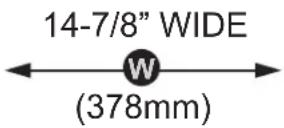
| Dimensions (W x D x H) | 14 7/8" x 23 3/8" x 33 3/4" (includes 3/4" panel, hinges, legs) |
| Net Weight | 104 lbs empty |
| Electrical Requirements | 115 V, 60 Hz, 3.5 A, 340 Watts, dedicated 15 A circuit |
| Refrigerant | R-513a |
| Water Supply Connection | 1/4" O.D. copper, cold water, 20 – 80 psi, 50° – 90°F |
| Drain Type | Built-in drain pump (3/8" ID hose) capable of discharging up to 8' above unit |
| Ambient Operating Temperature | 50° – 90°F (indoor / outdoor rated) |
| Door Reversibility | Yes, hinge side can be reversed (both stainless steel and panel ready models) |
| Venting | Front venting for undercounter installation |
| Bin Full Shutoff | Automatic – ice production pauses when bin is full |
| Materials | Stainless steel exterior (model SP), panel ready available |
| Maintenance Interval | Clean every 3–6 months; sanitize monthly |
| Warranty | 1 year parts & labor; 5 year limited compressor warranty |
| Safety Features | Grounded 3-prong plug, GFI required for outdoor, child entrapment prevention |
Frequently Asked Questions - XOUIM1565SP XO
User questions about XOUIM1565SP XO
0 question about this device. Answer the ones you know or ask your own.
Ask a new question about this device
Download the instructions for your Ice Maker in PDF format for free! Find your manual XOUIM1565SP - XO and take your electronic device back in hand. On this page are published all the documents necessary for the use of your device. XOUIM1565SP by XO.
USER MANUAL XOUIM1565SP XO
EVERY THING YOU NEED TO KNOW ABOUT YOUR
Xo
XOUIM1565S & XOUIM1565SP XOUIM1565O & XOUIM1565OP
UNDERCOUNTER GOURMET ICE MAKER
I worked really hard on this manual - so please read it...
XO

UNDERCOUNTER
When buying any XO appliance you can be confident you have chosen a high quality, innovative and stylish product from a company that cares about you! If you require service or have questions, Help is only a phone call away -
call: 973-403-8900
Talk to one of our undercounter experts.
CONGRATULATIONS
on purchasing your XO. Before you proceed, take just a moment to register your XO at:
www.xoappliance.com/register-your-product/
Ensuring warranty coverage should you need service Providing ownership verification for insurance purposes Let's XO notify you in the event of product changes or recalls.
WHERE THINGS ARE
Before You Get Started
4 - 7
Installer Checklist
Find Your Model
Safety Instructions
Electrical and Grounding Instructions
Installation Instructions
8 - 23
Sizes and Installation Dimensions
Plumbing
With & Without Drain Pump
Reversing the Door
Door panel Installation
Outdoor Use
Operating Instructions
24 - 26
Features & Specifications
Operating Instructions
Care and Cleaning
27 - 35
Stainless Steel
Interior Washing
Cleaning
Sanitization
Maintenance Schedule
Winterizing
Trouble Shooting
36 - 38
Before You Call For Service
Warranty
PLEASE READ AND FOLLOW ALL SAFETY INSTRUCTIONS
It's for your
own good...
Honest.
DEAR INSTALLER
HERES'S TEN STEPS FOR A QUICK & EASY INSTALL
① Inspect cabinet opening for water, drain and electrical connections.
The 1/4" O.D. water supply line must include isolation valve and should include an inline water filter (consult manual). Do NOT use a self-piecing valve for the supply connection. Water supply must have a minimum pressure of 20 psi and a maximum of 80 psi. Cold water should be between 50^ and 90^ - NOTE: warmer water will slow ice production. Water quality directly affects performance and product life - use of an inline water filter is strongly recommended.
Drain tubing will be 5/8" ID gravity fed or 3/8" ID for a pump model. All horizontal drain runs must drop 1/4" per foot. The drain should include an air gap device to prevent siphoning and a sanitary trap. A restricted or inadequate drain can result in poor ice production and possible flooding.
④ Electrical requirement is 15a dedicated, grounded circuit - outdoor installs must use a GFI.
Route water supply tubing to the water inlet located at the rear of the unit. Connect the drain tubing to either the pump discharge or the barbed gravity fed elbow. Be sure nothing is kinked, and excess slack is removed. Be sure the electrical connection is secure into the wall outlet.
⑥ Slide the machine into location or cavity being careful not to allow for any kinks to occur in the water inlet and drain tubing.
⑦ Adjust the Ice Maker to level using the leg levelers.
⑧ Add approximately 2-3 quarts of water to the bin and make certain it is draining properly and check for leaks. If water does not drain, stop and verify tubing is not restricted.
⑨ Wash down the interior of the machine with a mild detergent solution (consult manual)
Turn the machine on and allow it to make ice for approximately 30-35 minutes to verify ice is being produced and water is draining freely. Be sure to check the cube size, shape and clarity. Discard the first batch of ice.
adjust if needed.
Always do one last check to be sure all water and drain connections are leak free.
DANGER
RISK OF CHILD ENTRAPMENT!
An empty refrigerator is a very dangerous attraction to children.
Remove door gaskets, latches, lids, lock and/or doors from unused or discarded appliances, or take other actions to guarantee them harmless.
Always dispose of old appliances in accordance with local laws and regulations.
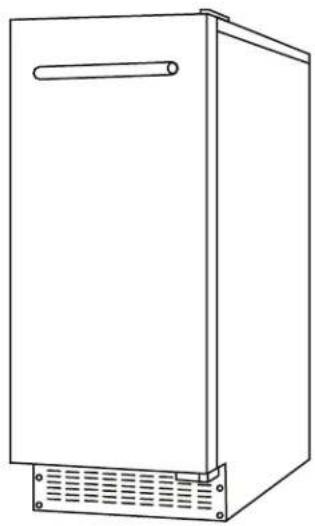
THESE ARE THE MODELS COVERED IN THIS BOOK
INDOOR / OUTDOOR
GOURMET ICE MAKER
natural_image
Line drawing of a rectangular cabinet with a handle and ventilation grilles (no text or symbols)STAINLESS STEEL
XOUIM1565S & XOUIM1565SP
PANEL READY
XOUIM1565O & XOUIM156OP
TAKE A MINUTE TO CIRCLE YOUR MODEL ABOVE
AND RECORD YOUR SERIAL NUMBER
HERE IN CASE YOU NEED IT LATER

YOUR SAFETY MATTERS
Please read through completely before using your XO Unit
Periodic maintenance is essential for safe operation - the unit must be easily pulled out for full access.
The appliance must be positioned so that the plug and water shutoff are readily accessible.
Empty your XO unit before attempting to move the appliance. Moving while loaded may damage or distort the frame.
The compressor will get HOT during operation / touching it may cause injury.
During installation follow all safety tips provided in this manual / appropriate safety equipment such as safety glasses and work gloves should be worn.
Two people should move or lift your XO unit to prevent injury or damage.
Remove all interior and exterior packing materials prior to installation and dispose of properly.
Always use only approved cleaning and descaling products to maintain your XO Ice Maker.
For maximum efficiency, keep the door tightly shut unless removing ice.
Before installing, allow your XO unit to sit upright for 2 hours at the install site. This will allow the cooling system to stabilize after transportation. Failure to follow this step may cause problems.
Never store bottles, cans or perishable food products such as meat or cheese in your XO Ice Maker.
Location
Your XO unit should be located away from direct sunlight and heat sources (stove, heaters, etc.) which may increase electrical consumption. High or low ambient temperature may cause units to work improperly. Optimal operation occurs in the ambient temperatures of 50^ - 68^ F and water temperature below 50^ .
The floor must be strong enough to support your XO unit fully loaded.
Your XO unit must not be installed in areas of where water or excessive moisture are present.
Your XO unit must not be installed near where flammable, corrosive or hazardous materials are present.
Your XO unit's final installation must observe the correct minimum air clearances around and behind the unit to ensure adequate ventilation. In addition, all ventilation openings must be kept clear and free of obstructions, failure to do so will result in damage to the unit.
WARNING
NEVER use external heat sources to accelerate defrosting
NEVER permit unauthorized service or modifications to your XO unit
NEVER tamper with the sealed refrigerant system - this unit uses R-513a Refrigerant.
It should never be used in the vicinity of any flammable or explosive ignition sources.
ALWAYS FOLLOW THE ELECTRICAL SAFETY INSTRUCTIONS OUTLINED IN THIS MANUAL.
ELECTRICITY - THIS IS SERIOUS
Failure To Follow All Electrical Safety Measures May Result in Serious Injury, Fire Or Death
All electrical work should only be performed by an experienced, licensed electrician.
All XO units MUST be grounded for safe operation and come equipped with a 3 Prong molded cord/plug for that purpose.
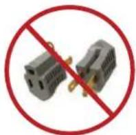
NEVER remove or disable the 3rd prong with an adapter.
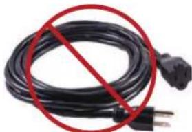
NEVER use an extension cord to operate your XO unit.
natural_image
Black cable with a red prohibition symbol crossed out, no text or symbols presentYour XO unit is built to operate on 115V 60Hz and should be plugged directly into a dedicated 15 amp 3 prong outlet. If you are uncertain as to the voltage, amperage capacity or if the 3rd prong is properly grounded - consult a licensed electrician.
To maximize the depth of the installation recess - your outlet should be mounted flush with the wall.
Your XO unit should not share the circuit with any other electrical devices as this may cause overloading, overheating, blown fuses or tripping circuit breakers. In a worst case this can pose a fire hazard.
NEVER handle your XO unit in wet conditions as this can pose a severe danger of electric shock.
Exercise care when moving your XO unit to avoid damage to the electrical cord. If the electrical cord of your XO unit becomes worn or damaged it must be replaced immediately by a qualified technician.
NEVER unplug your unit by pulling on the cord. Unplug by gripping the plug firmly and pull out straight from the outlet.
FOR INDOOR OR OUTDOOR USE:
XO Ice Makers shown in this manual are rated for Indoor and Outdoor use.
These units are designed to operate in ambient temperatures between 50° and 90°F.
Avoid installing the unit where it may be exposed to heat or direct sun, dusty or damp conditions or in a location where it may be rained on or splashed by water.
Never install the unit where flammable or corrosive chemicals (such as pool chemicals) are present.
Installation in seaside environments where high concentrations of salt are present will require more frequent cleaning to avoid corrosion.
Use in any uncontrolled area or otherwise exposed to the elements is hazardous and voids the warranty.
In regions where high humidity exists (greater than 70%) condensation may appear on the door and/or door gaskets. This is normal and will disappear as humidity drops.
SERVICE 115V - 60 Hz - 1 phase
AMPS 15 Amp Circuit Breaker
Requires a Dedicated Outlet
GFI required for Outdoor Installations
All electrical work must be performed by
a licensed electrician
State of California Proposition 65 Warning (US only) ⚠ WARNING
This product contains chemicals known to the State of California to cause cancer
and birth defects or other reproductive harm
For more information go to www.P65Warnings.ca.gov

Serious injury, fire or death... Okay -
You've got my attention!
A PERFECT FIT
INSTALL UNDER COUNTER
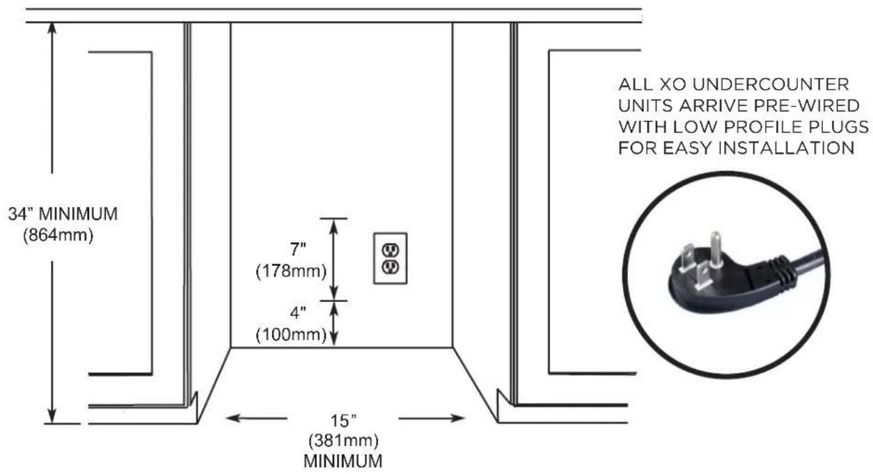
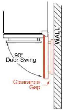
WHEN INSTALLING WITH THE HINGE SIDE NEXT TO A WALL - LEAVE ADEQUATE SPACE FOR YOUR DOOR HANDLE
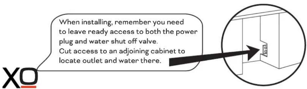
A PERFECT FIT
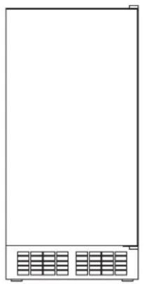
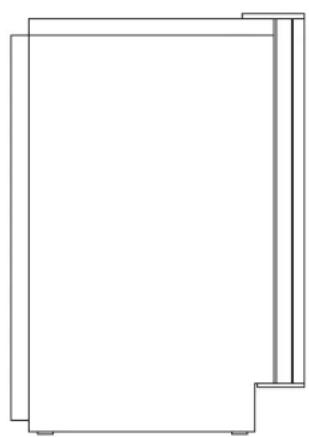
YOUR XO IS THIS BIG ( OR SMALL, AS THE CASE WOULD BE )
HEIGHT & WIDTH
XOUIM1565G & XOUIM1565GP ICE MAKER
natural_image
Front view of a rectangular electronic device with two side panels and a grid base (no text or symbols)
33-3/4" HIGH (857mm)
DEPTH
natural_image
Pure architectural line drawing of a rectangular frame with no text, numbers, or symbols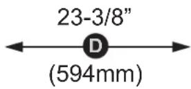
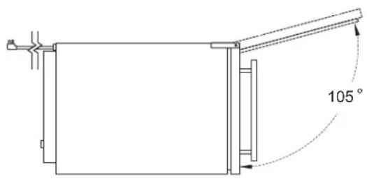
TOP VIEW
THE OVERALL DEPTH SHOWN (22-5/8") INCLUDES THE DOOR WITH 3/4" PANEL.
THE DEPTH OF THE ICE MAKER CABINET ONLY IS 21-3/16"
BEFORE YOU INSTALL
CHECK A FEW THINGS
Is the installation location COOL, DRY, LEVEL and away from direct sun.
The water supply valve must provide positive shut off capability and be readily accessible.
Does the unit have a dedicated 115V three prong grounded outlet? (use GFI outdoors)
The Cold Water supply is 1/4" O.D. tube, it should be 50° to 90°F and be between 20 and 80 psi. (NOTE: as the inlet water temperature increases - production efficiency goes down.)
YOU WILL NEED -
A few simple hand tools:
Pump pliers, adjustable wrench, #2 Phillips head screwdriver, level, razor knife
AND a few hardware items:
Teflon tape or Pipe dope
5/8" I.D. drain hose and hose clamps (if installing a gravity drain model)
1/4" O.D. water supply hose
Air Gap Device and/or Sanitary Trap (depending on your installation).
Water filter with isolation valve
Depending on your installation you will probably require additional site specific plumbing fittings
WATER QUALITY
All water contains some impurities and minerals.
Your XO Ice Maker is designed to produce crystal clear, gourmet ice. It does this by reducing the mineral content in the water as the ice is forming.
PURER WATER YIELDS PURER ICE.
Cubes are formed by cold water spraying against a chilled mold. Pure water freezes faster than water containing impurities. The spraying action causes the cubes to be built up in layers as the pure water freezes more quickly and the water containing impurities is washed away by the spray and falls into the water bin to be diluted and drained away.
When the ice maker senses the cubes are fully formed and ready, the ice cube molds are heated slightly causing them to drop out of the mold and into the ice holding bin.
Periodic maintenance is required to ensure that your ice maker is performing at its best. See the maintenance section of this book and the Maintenance Schedule.
FILTERS AND WATER TREAMENT
The correct filter is always recommended. It has the ability to remove odors as well as particulate from water prior to reaching the ice maker.
(consult www.xoappliance.com for more information on which filter is right for you)
Water softeners exchange one mineral for another (salt) which can cause inferior ice quality such as soft, mushy ice that clumps together. If you are using a water softener, you should install a bypass to supply untreated water to the ice maker.
Water produced by Reverse Osmosis and deionized water are not recommended. It is more corrosive than tap water and can cause harm to the equipment over time.
THE PLUMBING
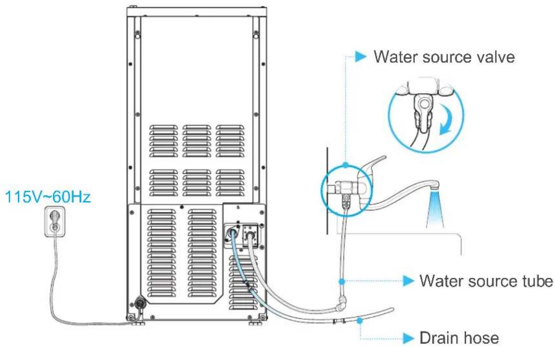
Plan the arrangement of the water supply pipes. You will need both a water supply line and a drain (see section on installing a gravity drain unit or pump drain unit)
Connect a 1/4" O.D. copper tube to the COLD tap water pipe and install a shutoff valve. Do not install the shutoff valve at the back of the product. Do not use a self-piercing valve. If the tap water has a high level of minerals, an inline filter will be required.
Attach the water supply line to the rear of the unit with flexible tube to the fitting indicated here. The tubing must be long enough to permit the unit to be pulled out for service.
Water supply should be between 20psi and 80psi.
Attach the drain to the connection indicated here If you are installing an XOUIM1565S unit with a gravity drain, the line must be pitched down 1/4" per ft to ensure correct drainage.
If the drain is positioned at a higher elevation than the connection on the rear of the unit, a pump will be required. Use model XOUIM1565GP. This unit comes with a pre-installed drain pump capable on discharging to a drain up to 8' above the unit.
IMPORTANT: The keep drains as short and straight as possible for optimal performance.
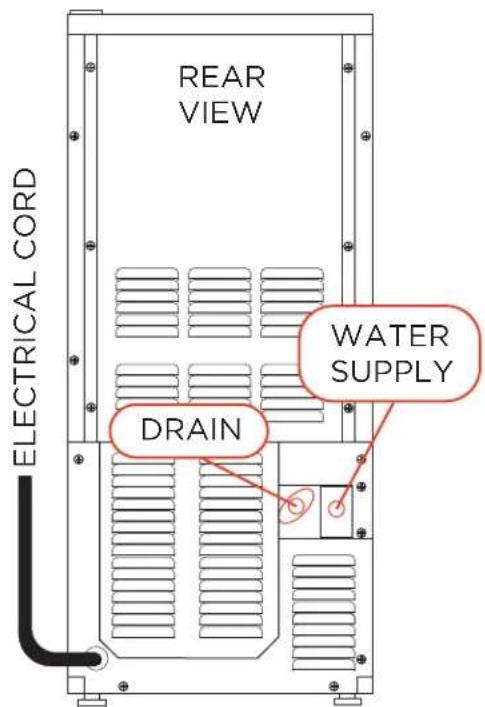
The electric power, water supply pipeline and drain pipeline must be in compliance with all provisions under the local laws and building regulations.
IMPORTANT: The product is designed for use in a fixed condition but it may be required to pull the product out for service. Therefore, do not install any material at the front, upper or lower end of the product which may be an obstacle when pulling the product out.
Once the unit is in place, use the leveling legs to ensure the unit is level. Each side should have at least 1/16" of space for projection of the screw head near the bottom.
WITH GRAVITY DRAIN
INSTALLING THE XOUIM1565S without a drain pump.
Position the ice maker in front of the opening. Level the unit using the leveling legs.
Wash and flush the water supply tube and connect the unit to the cold water isolation valve.
Prepare the drain. The drain must be pitched downward at a drop of 1/4" per foot to drain properly.
Horizontal runs of 5' or more must be anchored to a wall for support to prevent sagging.
A sanitary trap and air gap must be installed in the line prior to entering the home's drain system.
The trap prevents sewer gas from flowing back to the ice maker.
The air gap device prevents siphoning drain water back into the ice maker.
Cut the 5/8" ID drain hose (not supplied) to the required length. Immerse the hose in warm water to make installation easier, then using a threaded hose barb connection sealed with teflon tape, connect the drain hose to the drain using hose clamps.
Turn the water supply on and check to ensure there are no leaks.
If there are no leaks, plug the unit into the electrical outlet.
Press the switch to the "ICE" position. The compressor will run approximately 3 - 5 minutes.
Slide the unit back into it's final position and recheck to ensure it is level.
REMEMBER to adhere to all local building codes and regulations
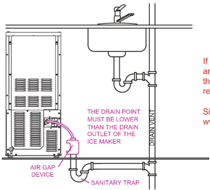
If you purchase a gravity drain unit and find you need one with a pump the XOUIM1565S can easily be retrofitted with one in the field.
Simply order a XOUIMPUMP from www.xoappliance.com
WITH DRAIN PUMP
INSTALLING THE XOUIM1565SP with DRAIN PUMP.
Position the ice maker in front of the opening.
Level the unit using the leveling legs.
Wash and flush the water supply tube and connect the unit to the cold water isolation valve.
Cut the 3/8" diameter drain hose to the required length. Immerse the hose in warm water to make installation easier, then connect the drain hose to the drain using hose clamps.
(9' of 3/8" ID drain hose is included with pump models)
IMPORTANT: Check local codes to determine if an air gap is required between the drain and the pump.
Turn the water supply on and check to ensure there are no leaks.
If there are no leaks, plug the unit into the electrical outlet.
Fill the ice container with clean tap water approximately 3/4 full. The drain pump should turn on and pump the water out. Check again for leakage.
Press the switch to the "ICE" position. The compressor will run approximately 3 - 5 minutes.
Fill the ice container to 3/4 full once more. Block the drain tube while the pump is running. The pump should continue to run.
Slide the unit back into it's final position and re-check to ensure it is level.
REMEMBER to adhere to all local building codes and regulations
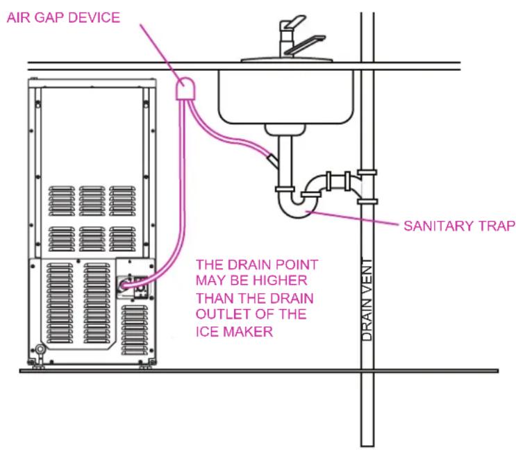
REVERSING THE DOOR
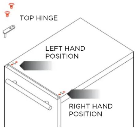
Your XO Ice Maker is shipped with the hinge on the right hand side but it can be easily reversed. IMPORTANT NOTE: Stainless Steel door models and Panel Ready models use different hinges and Panel Ready models require additional steps when reversing the door.
- While supporting the door, remove the two (2) screws (shown in RED) that hold the Top Hinge in place.
Remove the door by lifting it straight up.
The Top Hinges are virtually the same for Stainless Steel and Panel Ready models.
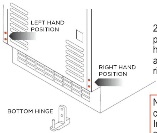
- Remove the two (2) screws that hold the Bottom Hinge in place. Remove the two (2) corresponding screws on the left hand side. Install the Bottom Hinge in the left hand position and install the remaining two (2) screws into the holes on the right hand side.
NOTE: The Panel Ready unit has an additional screw that comes up from the bottom that must be also be removed. In addition, you must reverse the DOOR STOP INSERT shown in Step 2A before re-installing.
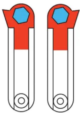
2A. Panel Ready Units Only: Before re-installing the bottom hinge on the left side, you must reverse the DOOR STOP INSERT located on the underside of the bottom hinge. Simply remove the hex head bolt that doubles as the hinge pin (shown in BLUE) - flip the stop over (shown in RED) and re-install the hex head bolt.
VIEWS OF BOTTOM HINGE SEEN FROM BELOW BEFORE AND AFTER REVERSING THE STOP
natural_image
Two identical test tubes with red and blue components, no text or symbols visibleREVERSING THE DOOR CONT.
- At the rear of the unit, there are three (3) screws along the top. Remove these screws. On the top front of the unit, there is one (1) additional screw on the left hand side, remove this screw. The Top Cover plate will now lift off.
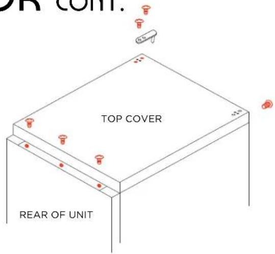
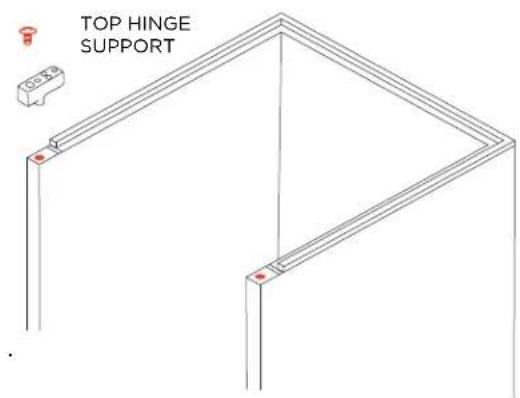
- Remove the Top Hinge Support which is held in place by one (1) screw from the right hand side and transfer it to the left hand side re-attaching it with the screw.
Replace the Top Cover plate using the three (3) screws along the rear of the unit. The screw removed from the top front on the left hand side - must be screwed into the corresponding hole on the right hand side. Remove the plugs from the left hand side screw holes on the top cover and door and move them to the right hand side.
Panel Ready Units Skip to Step 5A
- Center the hole in the bottom left hand side of the door on the bottom hinge pin and slide the door down into place. Install the top hinge using the two screws removed in Step 1.
5A. Panel Ready Units Only:
Turn the door so the bottom edge is facing up.
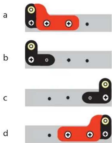
a Remove the DOOR STOP (shown in RED)
b Remove the ANGLE BRACKET (shown in Black)
c Flip the ANGLE BRACKET over and install using one screw at the other side of the door.
d Replace the DOOR STOP with the mirror image door stop supplied with the unit using the screws removed earlier.
Pop the small plastic bushing out and replace it after the panel is installed. SKIP TO STEP 2 ON PAGE 20
LET'S FACE IT
OVERLAY PANEL DIMENSIONS XOUIM15650 & XOUIM15650P
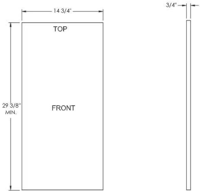
The panel has a minimum height of 29 3/8" - If making the panel 29 3/8" tall no further adjustments are needed.
If the panel is taller than 29 3/8" proceed to pages 18 and 19, a notch or recess is required.
natural_image
3D rendering of a mechanical bracket with mounting holes and a highlighted section (no text or symbols)

WATCH THE INSTALLATION VIDEO ON OUR CHANNEL
https://www.youtube.com/channel/UCT-lp-dM9hoPydpxZfrZzRA www.xoappliance.com
AFTER INSTALLTION UNDER COUNTER, OVERLAY DOOR MUST BE ABLE TO OPEN 90°.
PANEL MAXIMUM WEIGHT: 20 lbs.
MAXIMUM PANEL THICKNESS 3/4"

LET'S FACE IT
OVERLAY PANEL DIMENSIONS XOUIM15650 & XOUIM15650P
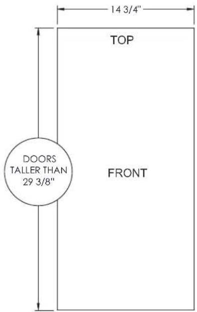
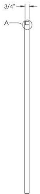
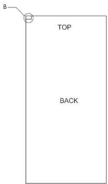
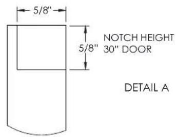
Door panels taller than 29 3/8" require a notch as seen in Detail A & B on the hinge side. If making the panel 29 3/8", no notch (detail A,B) is required.
The bottom of the notch should always be 29 3/8" from the bottom of the panel. To get the exact measurement subtract 29 3/8" from the panel height.
30" 5/8" 30 1/4" 7/8"

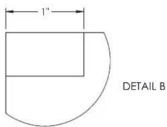
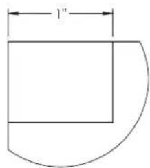
AFTER INSTALLTION UNDER COUNTER, OVERLAY DOOR MUST BE ABLE TO OPEN 90°.
PANEL MAXIMUM WEIGHT: 20 lbs.
MAXIMUM PANEL THICKNESS 3/4"

LET'S FACE IT
OVERLAY PANEL DIMENSIONS XOUIM15650 & XOUIM15650P
HANDLING HANDLELESS DOORS:
Handleless doors have a profile similar to that shown
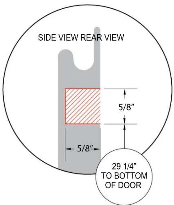
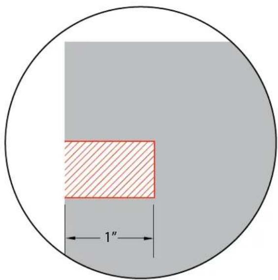
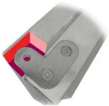
Instead of a notch, if the design of the door will allow, a recess can be cut out with a router to accommodate the hinge extension.
The bottom of the recess must be 29 1/4" up from the bottom of the door and 5/8" high - the door, at the deepest point of the finger groove, must be at least 30" from the bottom of the door.
AFTER INSTALLTION UNDER COUNTER, OVERLAY DOOR MUST BE ABLE TO OPEN 90°.
PANEL MAXIMUM WEIGHT: 20 lbs.
MAXIMUM PANEL THICKNESS 3/4"

INSTALLING THE OVERLAY PANEL
Installing the overlay panel is easy if you follow these simple steps.
You will need the following tools:
A drill with 3/16" and 5/16" bits - and a #2 Phillipshead screwdriver
- While supporting the door, remove the two (2) screws (shown in RED) that hold the Top Hinge in place.
Then remove the door by lifting it straight up.
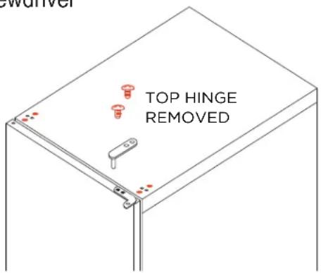
- Place the door face down on a flat surface and remove the door gasket from the groove (shown in RED) gently starting at one corner. Lay it flat in a safe place, you will be replacing it shortly.
In the four (4) corners of the groove, you will see four (4) holes. These are for screws that will assist in securing the panel.
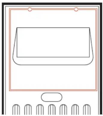
natural_image
Simple line drawing of a rectangular object inside a container with six side panels (no text or symbols)- Before proceeding, attach the handle (if used) to your overlay door panel in the desired position remembering to countersink the screw heads so they do not prevent the overlay panel from laying flat against the door.
- Attach the BLACK support plate to the bottom of the door using the three (3) screws (shown on RED).

INSTALLING THE OVERLAY PANEL
- Center the panel on the door and clamp it in place to prevent shifting during attachment.
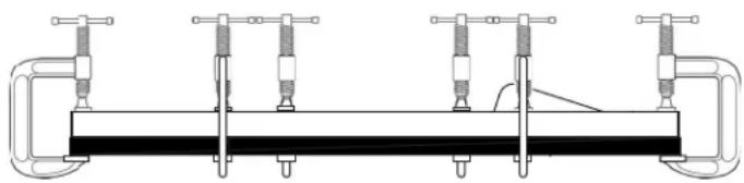
natural_image
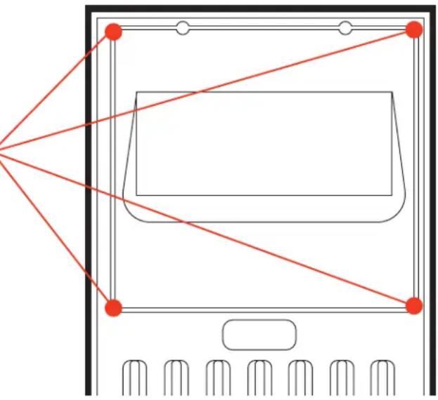
Technical line drawing of a mechanical clamp or clamping device with multiple vertical rods and a central horizontal bar (no text or symbols)- Using the HINGE ANGLE BRACKETS installed on the door as a guide, drill two holes: One 3/16" Hole down from the top into the door 1/2" deep. Remove the plastic bushing from the lower angle bracket. One 5/16" Hole up from the bottom into the door 1/2" deep. Replace the plastic bushing into the lower angle bracket. This is to accommodate the hinge pins.
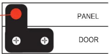
-
Taking care not to drill through the panel - using the holes in the door, drill a 1/8" pilot hole 5/8" deep in each of the four screw holes located in the corners of the gasket groove (ref: Step 2).
-
Using the four (4) self tapping screws provided install one screw into each one of the four holes.
natural_image
Pure diagram of a computer monitor with red connecting lines and control buttons, no text or symbols present.- Drill a 1/8" pilot hole 3/4" deep in each of the three screw holes located in the BLACK support plate mounted to the bottom of the door into the bottom edge of the panel. Using the three (3) screws provided (shown in RED) secure the panel from the bottom to the support plate.

INSTALLING THE OVERLAY PANEL
-
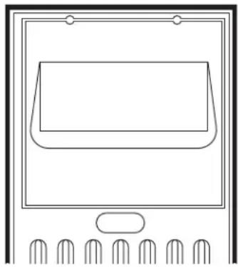
Remove clamps and any debris that may remain from drilling the pilot holes from the door gasket groove.
-
Beginning at one corner, replace the door gasket by pressing it into the groove it was removed from in Step 2.
natural_image
Line drawing of a monitor with a blank screen and five side buttons (no text or symbols)- Replace the door by lowering it onto the lower hinge pin and replacing the top hinge removed in Step 1.
FOR OUTDOOR USE
When using your XO Ice Maker outdoors - follow these additional steps.
Different regions of the country can have radically different seasonal weather which can affect performance and the influence your selection for the physical location of the unit.
In outdoor installations care must be taken to protect the unit from excessive heat or direct sun, dusty or damp conditions or in a location where it may be rained on or splashed by water.
The unit must be connected to a grounded circuit. If the installation is outdoor it must be protected by a Ground Fault Interrupter (GFI). If you are uncertain if the circuit is correctly grounded and protected, consult a licensed electrician.
These units are designed to operate in ambient temperatures between 50^ and 90^ F.
As the ambient temperature approaches either extreme the production capacity of the ice maker will be reduced. This is normal and expected.
Never install the unit where flammable or corrosive chemicals (such as pool chemicals) are present.
Installation in seaside environments where high concentrations of salt, or in pool areas where high concentrations of chlorine are present will require more frequent cleaning to avoid corrosion.
Use in any uncontrolled area or otherwise exposed to the elements is hazardous and voids the warranty.
In regions where high humidity exists condensation may appear on the door and/or gasket seals.
CAUTION: Exposing the Ice Maker to freezing ambient temperatures can cause water throughout the installation to freeze where it is not supposed to and may result in damage to the unit.
Seasonally, once temperatures at the coldest part of the day begin to approach 40^ F you should take steps to winterize your ice maker following the steps in this manual.
FEATURES & SPECS
Produces up to 65lbs of crystal clear, gourmet ice per day
Rectangular Bell Shaped Cubes - designed to melt slowly and cool beverages while minimizing dilution
Gravity drain and pump drain models available
Reversible Panel Ready steel door
natural_image
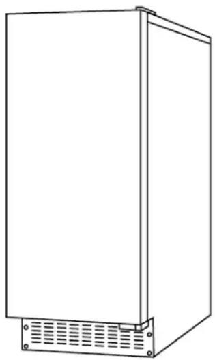
Line drawing of a rectangular industrial enclosure with ventilation grilles and mounting feet (no text or symbols)Front venting - designed for under counter installation
Rated for Indoor or Outdoor use (50° - 90°)
Automatically pauses ice production when bin is full
| MAXIMUM CAPACITY | 65 lbs per day |
| CUBES per CYCLE | 24 |
| TIME per CYCLE | 20-30 min |
| DIMENSIONS (WxDxH)* | 14 7/8" x 23 3/8" x 33 3/4" |
| NET WEIGHT | 104 lbs empty |
| ELECTRICAL | 115V - 60hz - 3.5 amps |
| POWER CONSUMPTION | 340 Watts |
| REFRIGERANT | R-513a |
| COOLING CAPACITY | 723 kcal/hr (2@ 45°F) |
| INLET WATER TEMP. | 50° - 90° F |
| INLET WATER PRESS. | 20 - 80 psi |
| AMBIENT TEMP. | 50° - 100° F |
* Overall Dimensions include 3/4" panel, hinges and legs
OPERATING
Initial operation
① Open the water supply valve connected with the ice maker.
② Insert the plug of the ice maker into the electric outlet.
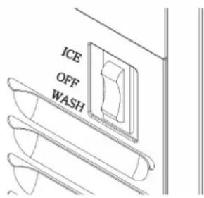
③ Open the door and turn the switch to the "ICE" position."
④ Discard the first batch of ice.
⑤ Good-quality ice is produced 1-2 hours later.
Using the ice maker
Use of the ice maker is very simple. Simply turn the switch at the lower end of the product to the “ICE” position.
The product automatically starts ice production, which continues until the ice container has been filled with ice. Remove the ice using an ice scoop and insert the scoop into the holder on the inside of the container (If you place the container in the ice, it may be covered over by ice).
The ice maker produces 24 pieces of ice every 30 minutes. Also, the produced ice drops down into the ice container; water is supplied to the ice maker and the water is also drained.
Important Information : Do not put anything other than ice in the ice container. Wine or beer bottles are unsanitary and a detached label may block the drain pipe.
Ice
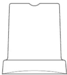
The ice has a rectangular bell shape (refer to the figure).
Newly produced ice is clear and transparent. The inside of the ice is sometimes cracked; however, such cracks commonly occur in the production process and disappear with time.
Ice stored in the container for a long time may gather frost on the outside and look cloudy. This is normal ice and, once water is poured on the ice, such frosting disappears.
natural_image
Simple line drawing of a rectangular object with a curved base and top (no text or symbols)Ice container
The product continues making ice until the level of ice reaches the temperature sensing tube(right side). It then ceases operation. The model with a drain pump drains away melted ice when the ice maker is turned off. The pump works for only several seconds.
OPERATING CONT.
Operation time
It takes about 20-35 minutes to produce a set of 24 ice pieces. The length of one cycle of the ice maker (ice production and ice removal) differs depending upon the cleanness of the ice maker, the surrounding temperature, and the temperature of the water supplied to the ice maker. It takes about 10-12 hours to fill the empty ice container with ice.
Ice production
The ice production process largely consists of two cycles-ice production and ice removal. 24 pieces of ice are produced with each cycle of ice production and ice removal.
When water is sprayed on to the surface of the frozen ice forming mold, the ice production cycle is started. When ice is removed and water is supplied to ice maker, the ice removal cycle is started. The time taken for both cycles together is about 20-35 minutes.
Ice production cycle
Ice is produced on the surface of the ice -forming mold located at the top of the ice maker. Water is sprayed against the chilled surface of the mold where it begins to freeze. Water containing mineral impurities freezes more slowly and it falls back into the water container where it will be diluted and drained off during the Ice Removal Cycle. This process of spraying water allows ice to form in crystal clear layers.
As the ice-forming mold is filled with ice the temperature drops, the ice maker senses this and the ice production cycle stops and ice removal is started automatically.
Ice removal cycle
The compressor works during the ice removal cycle, but the pump motor and fan motor are stopped. The hot gas valve and water supply valve are opened and the frozen surfaces are heated, causing ice to drop into the container. The ice removal cycle is stopped and the ice production cycle is started again automatically.
STAINLESS STEEL
CLEANING THE EXTERIOR
Stainless Steel:
Stainless steel does not stain, corrode, or rust as easily as ordinary steel, but it is not stain or corrosion proof. Stainless steels can discolor or corrode if not maintained properly.
Stainless steels differ from ordinary carbon steels by the amount metals such as chromium and nickel used in the alloy. It is the chromium which provides an invisible protective film on the surface called chromium oxide. If the protective chromium oxide film on the surface is damaged or contaminated, it can result in discoloration, staining, or corrosion of the iron in the steel.
Care & Cleaning:
Routine cleaning of the stainless steel surfaces will serve to greatly extend the life of your product by removing contaminants.
This is especially important in coastal areas which can expose the stainless to severe contaminants such as halide salts, (sodium chloride) and also in pool areas where high concentrations of chlorine are present.
It is strongly recommended to periodically inspect and thoroughly clean crevices, weld points, under gaskets, rivets, bolt heads, and any locations where small amounts of moisture could collect, become stagnant, and concentrate contaminates.
Additionally, any mounting hardware that is showing signs of corrosion should be replaced.
The frequency of cleaning depends upon the installation location, environmental factors, and use.
Cleaning Products:
Ultimately, the choice of a proper cleaning product belongs to the consumer, and there are many products to choose from. Depending upon the type of cleaning and the degree of contamination, some products are better than others.
Typically the most effective means of routine cleaning for most stainless steel products is to give the surfaces a brisk rubbing with a soft cloth soaked in warm water with a gentle detergent, or mild mixture of ammonia.
Rubbing should follow the polish lines of the steel, followed by a thorough rinsing after cleaning.
CAUTION: There are products on the market Called "stainless steel cleaners," which may contain abrasives that could scratch the surface, (compromising the protective chromium oxide coating) and other products which contain chlorine bleach which will dull, tarnish or discolor the surface if not completely removed. Such cleaners should be avoided.
WASHING (INTERIOR)
Proper maintenance, cleaning and santizing is essential to ensure your ice is safe, fresh and odor free.
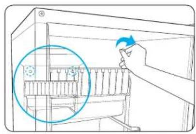
Cleaning the nozzle / ice slide / water tank
-
Open the door and remove two front injection bolts on the top cover.
-
Pull the top cover to remove it.
-
Slightly lift the ice slide to remove it.
-
Clean the slide with soft plastic brush or sponge.
natural_image
Line drawing of a hand inserting a component into a rack, with a magnified inset showing the rack structure (no text or symbols)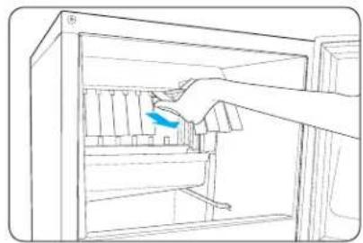
natural_image
Line drawing of a hand inserting a component into a refrigerator (no text or symbols)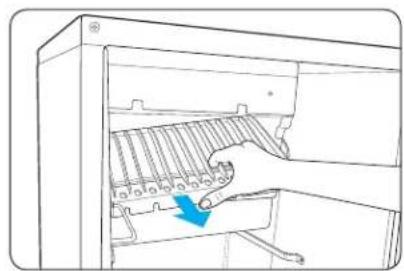
natural_image
Line drawing of a hand inserting a rack into a computer tower (no text or symbols)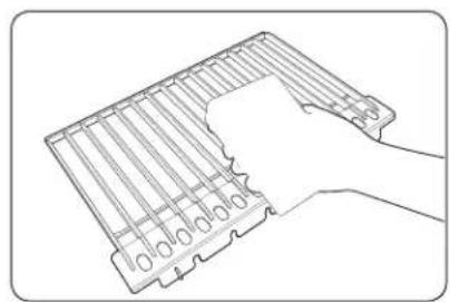
natural_image
Line drawing of a hand holding a tray with a grid and circular elements (no text or symbols)WASHING (INTERIOR) CONT.
Proper maintenance, cleaning and santizing is essential to ensure your ice is safe, fresh and odor free.
- Clean the gap of the nozzle frame fixed on the vessel sheet (water tank).
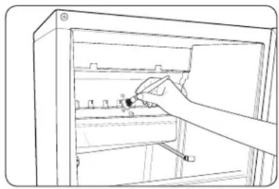
natural_image
Line drawing of a hand inserting a component into an open refrigerator (no text or symbols)- Lift the drain connection inside the vessel sheet (water tank), clean it, and drain the water.
* The drain connection must be re-assembled in the correct position after cleaning or it will continue to drain and be unable to make ice.
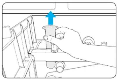
natural_image
Illustration of a hand holding a mechanical component with an upward arrow, no text or symbols presentCLEANING THE ICE TANK AND WATER TANK FILTERS
Empty the ice tank and prepare a cleaning solution by mixing 2 tablespoons of dishwashing detergent with 2 gallons of warm water (95\~115°F).
Soak a clean cloth in the solution and clean the inside of the ice tank. Pour an appropriate amount of the solution into the drain pipe, and allow to air dry.
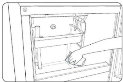
natural_image
Line drawing of a hand cleaning or removing a door panel (no text or symbols)* Press the switch to set it to (WASH) when cleaning the product; this will repeat the process of supplying water for about 2 minutes and operating the circulation pump 3 times, enabling easier cleaning.
WASHING (INTERIOR) CONT.
Proper maintenance, cleaning and santizing is essential to ensure your ice is safe, fresh and odor free.
Cleaning the ice tank and water tank filters
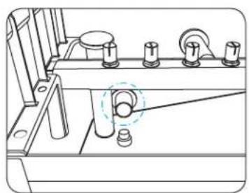
natural_image
Technical line drawing of a mechanical assembly with no visible text or symbolsWATER TANK
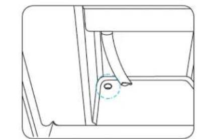
natural_image
Technical line drawing of a mechanical component with a curved handle and mounting hole (no text or symbols)ICE TANK
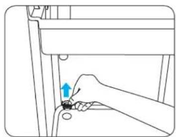
natural_image
Line drawing of a hand adjusting a small component with a blue arrow indicating the step (no text or symbols present)Always unplug the unit before performing maintenance.
Open the door of the Ice Maker and remove the filter screens from the bottom of the water tank and ice tank (position indicated above).
Rinse them clean thoroughly with running water.
Replace the tank filters in the positions shown.
Failure to perform this simple maintenance can cause the water nozzles and drain to become clogged and lead to reduced performance and/or damage to the unit.
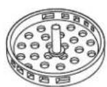
BOTTOM FILTER SCREEN
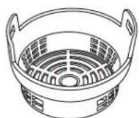
TOP FILTER SCREEN
THE CONDENSER IMPROVE EFFICIENCY & PERFORMANCE
Cleaning the condenser
Remove dust and dirt from the surface of the condenser coils with a vacuum cleaner
Remove two screws on the front panel at the center of the inside
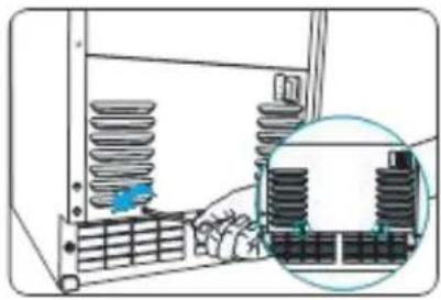
natural_image
Diagram of a mechanical assembly with spring-loaded components and a magnified inset showing internal structure (no text or symbols)Vacuum the condenser coils
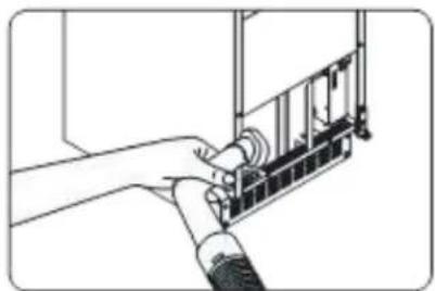
natural_image
Diagram of a hand connecting a device to a panel, showing internal components (no text or symbols)Reassemble the panel using the two screws to after cleaning
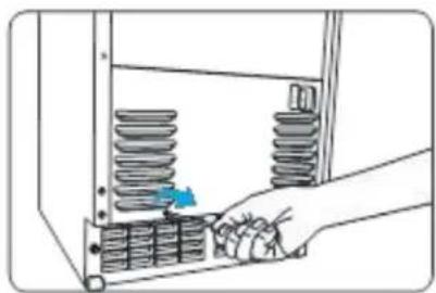
natural_image
Illustration of a hand inserting a spring into a rack, with no visible text or symbolsCLEANING/DESCALING
Ice makers must be thoroughly cleaned a minimum of 2-4 times each year, more frequently if circumstances require it.
All cleansers and sanitizing agents must comply with 40CFR 180.9403 as Food Contact Sanitizers.
The end user is responsible for maintaining this ice maker in accordance with the instructions in this manual. Failure to do so may void warranties and cause an unsafe condition. Basic sanitization and maintenance will both increase reliability and performance, as well as reduce the consumption of electricity and water.
Maintaining the ice maker according to these instructions will minimize unwanted repairs and extend the unit's service life.
Maintenance activities must be performed either by the consumer or by an authorized service technician at required intervals.
If you are unfamiliar with sanitization procedures, contact your dealer or XO Customer Service at 973-403-8900 for service.
GENERAL:
Thoroughly clean the ice maker every three to six months for efficient operation.
If the ice maker needs to be cleaned and sanitized more frequently, consult a certified service company for water quality testing and take appropriate action.
Based on the condition of the ice maker it may be necessary to disassemble parts of the unit for cleaning and disinfection.
Caution: Use only the certified ice-maker detergent and disinfectant. (The detergent can be purchased at your dealer).
Please read all labels printed on the container before use. Do not mix the detergent and the disinfectant.
Warning: Wear rubber gloves and goggles (or face cover) when using the detergent or the disinfectant.
PREPARATION:
Ice maker detergent is used to remove mineral deposits such as lime marks. It cannot be used to remove mold or adhesive mucus.
Mix Nickel Safe detergent and water in a plastic or stainless steel container following the manufacturer's recommendations.
THE PROCESS:
Turn the switch to OFF - the machine will automatically complete making and separating ice, then stop.
Caution: Do not forcibly remove ice from the evaporator. It can damage the evaporator.
Remove all ice from inside of the tank.
Before proceeding, shut down the power to the icemaker at the breaker or by unplugging it.
Wash the ice scoop including the handle regularly with other food containers.
WARNINGS:
• The detergent may cause burns.
- If you accidentally drink the detergent, do not force yourself to vomit.
- Instead, drink large amount of water or milk and contact your doctor immediately.
- If the detergent gets on the skin, wash with water.
- Keep the detergent out of children's reach.
CLEANING CONT.
If necessary, remove the top cover and disassemble the evaporator cover, water curtain, ice guide and nozzle frame.
Place all components into a basin to soak with approximately 3 quarts of the detergent water mixture for 5 to 20 minutes depending on how much lime scale build up is present.
Disassemble the spray bar by removing the left and right silicon plugs, and separate the nozzles and inserts while soaking.
While the parts are soaking, clean the inside of the ice tank with a soft brush and rinse every corner of the inside door, reservoirs, evaporator frame and evaporator upper pipe part with clean water.
Clean the parts which have been soaking with a soft nylon brush. You may have to use a toothpick to clear the nozzles.
After cleaning, rinse all the parts with clean water.
Re-assemble the unit with the newly cleaned parts.
Pour the remain quart of detergent mixture into the water tank.
Make sure the switch is in the "OFF" position and restore power by plugging the unit in or turning on the breaker.
AUTOMATIC CLEANING:
Start the automatic cleaning process by turning the switch to the "WASH" position.
The automatic cleaning cycle takes 21 minutes to complete. After it is finished set the switch in the "OFF" position.
RINSING:
If any cleaning solution remains in the water tank, remove the drain plug to empty the tank.
Re-install the drain plug, pour one quart of clean water into the water tank and run "WASH" again for 10 minutes.
If any bubbles or residue remains, repeat the rinse operation.
SANITIZING
Ice makers must be sanitized monthly, more frequently if circumstances require it.
All cleansers and sanitizing agents must comply with 40CFR 180.9403 as Food Contact Sanitizers.
The end user is responsible for maintaining this ice maker in accordance with the instructions in this manual. Failure to do so may void warranties and cause an unsafe condition. Basic sanitization and maintenance will both increase reliability and performance, as a well as reduce the consumption of electricity and water.
Maintaining the ice maker according to these instructions will minimize unwanted repairs and extend the unit's service life.
Maintenance activities must be performed either by the consumer or by an authorized service technician at required intervals.
If you are unfamiliar with sanitization procedures, contact your dealer or XO Customer Service at 973-403-8900 for service.
GENERAL:
Sanitize the ice maker every month for safe and efficient operation.
If the ice maker needs to be cleaned and sanitized more frequently, consult a certified service company for water quality testing and take appropriate action.
Based on the condition of the ice maker it may be necessary to disassemble parts of the unit for cleaning and disinfection.
Caution: Use only the certified ice-maker detergent and disinfectant. (The detergent can be purchased your dealer.)
Please read all labels printed on the container before use. Do not mix the detergent and the disinfectant.
Warning: Wear rubber gloves and goggles (or face cover) when using the detergent or the disinfectant.
PREPARATION:
Prepare disinfectant (6.7 oz of 5.25% Sodium Hydroxide mixed in 5 liters of water).
THE PROCESS:
Turn the switch to OFF - the machine will automatically complete making and separating ice, then stop.
Caution: Do not forcibly remove ice from the evaporator. It can damage the evaporator.
Remove all ice inside of the tank.
Before proceeding, shut down the power to the icemaker at the breaker or by unplugging it.
Wash the ice scoop including the handle regularly with other food containers.
Remove the top cover and disassemble the evaporator cover, water curtain, ice guide and nozzle frame.
Place all components into a basin to soak with approximately 2 quarts of the disinfectant water mixture for 10 minutes
While parts are soaking, scrub the inside of the ice tank with a soft brush and rinse every corner of the inside door, reservoirs, evaporator frame and evaporator upper pipe part and rinse with clean tap water to avoid cross-contamination.
Rinse the parts which have been soaking with clean tap water to avoid cross contamination.
Re-assemble the unit with the newly cleaned parts.
Pour 3 quarts of disinfectant mixture into the water tank.
SANITIZING CONT.
Make sure the switch is in the "OFF" position and restore power by plugging the unit in or turning on the breaker.
AUTOMATIC SANITIZING:
Start the automatic sanitizing process by turning the switch to the "WASH" position. This will also sanitize the piping.
The automatic sanitizing cycle takes 21 minutes to complete. After it is finished set the switch in the "OFF" position.
RINSING:
If any disinfectant solution remains in the water tank, remove the drain plug to empty the tank.
Re-install the drain plug, pour one quart of clean water into the water tank and run "WASH" again for 10 minutes.
Do NOT wipe the interior dry.
Turn on the "ICE" function and the unit will resume making ice.
Discard the first batch of ice after sanitizing.
MAINTENANCE SCHEDULE
Proper maintenance assures better ice and longer product life.
Shown below is a recommended service schedule to maintain your ice maker at peak performance. Failure to provide maintenance as prescribed in this manual may void warranty.
The intervals shown are based on average conditions, your unit may require more frequent maintenance based on your particular installation, such as areas where hard water, dust or salt air are present.
If your ice maker has been winterized, you must wash, sterilize and clean/descale it thoroughly before returning it to service to ensure that any detergents or chemicals have been completely flushed from the system.
Always discard the first batch of ice made after restarting.
WINTERIZING
Where seasonal installation ambient temperatures fall below 50^ F
Clean and sanitize your system
Turn off the power
Empty the water container completely
Disconnect the pump hose - this requires the removal of the back panel
Close the water supply valve and disconnect the water supply line from the rear of the unit
Turn on the power and set the switch to the "WASH" position.
This will open the internal water supply valve allowing it to drain the inlet pipe
If your unit has a drain pump, pour 1/2 gallon of RV anti-freeze mixture (propylene glycol) into the ice tank.
WARNING: Do NOT use anti-freeze intended for automobiles.
Turn the ice maker "OFF" and remove the plug from the outlet
When returning the ice maker to service - the unit must be thoroughly santized and cleaned to ensure all chemicals and detergents are flushed from the system.
Discard the first batch of ice after returning to service.
IMPORTANT NOTE:
Should the ice maker require adjustment of the:
Evaporator temperature sensor,
Ice production cycle time delay - or -
Water supply timer
Call Customer Service, do not attempt yourself.
TROUBLESHOOTING
| PROBLEM | POSSIBLE CAUSE | CHECK THIS |
| Unit does not operate | Ice maker is unpluggedBreaker trippedSwitch turned to “OFF”The ice tank is full | Plug ice maker inReset breaker - if it happens again, call for serviceTurn switch to “ICE”Ice detection sensor is activated |
| Cubes are too large | Low ambient temperatureIce thickness control does not work | Call Customer ServiceCall Customer Service |
| Cubes are too small | High ambient temperatureToo little water in the water tankThe water nozzle not sprayingIce thickness control does not work | Call Customer ServiceCheck the water supplyCheck the water supply | nozzle may be cloggedCall Customer Service |
| Ice is fragmented | Nozzle partially blocked | Clean the ice maker |
| Ice tank not filling | Check the operation timeCheck for water in the ice tank | Requires approx 12 hrs to fill ice tankCheck and clean drain |
| Ice cubes are white | Low water in water tank | Check water supplyCheck for cracks or leaks |
| Unit is runningbut no ice is made | Low water in water tankIce cubes are stuck on the moldWater does not get coldWater not sprayingCondenser coils dirtyCondenser not workingHigh ambient temperatureHot gas leakNeeds refrigerant | Check water supplyCheck water supply | Check hot gas valveCheck water supply | Contact customer serviceLow water in water tank | Check circulation pumpVacuum condenser coilsCheck condenser fanCall Customer ServiceCall Customer ServiceCall Customer Service |
Questions - Need Help...
You can always contact customer service at 973-403-8900
or visit www.xoappliance.com
WE'VE GOT YOUR BACK
ONE-YEAR PARTS & LABOR LIMITED WARRANTY. XO warrants to the original purchaser of every new XO refrigerated unit, the cabinet and all parts thereof, to be free from defects in material or workmanship under normal and proper use and maintenance as specified by XO and upon proper installation and start-up in accordance with the instruction packet supplied with each XO unit. XO's obligation under this warranty is limited to a period of one (1) year from the date of original purchase.
FIVE-YEAR COMPRESSOR LIMITED WARRANTY. XO warrants its compressor to be free from defects in both material and workmanship under normal and proper use and maintenance service for a period of five (5) years from the date of original purchase. If the compressor fails during that time period due to a defect in material or workmanship, XO will supply a replacement compressor free of charge. The consumer will be responsible for all related transportation and labor costs. Product must be registered with XO to qualify for this warranty.
TERMS APPLICABLE TO EACH WARRANTY. Any part covered under the above warranties that is determined by XO to have been defective within the time frame is limited to the repair or replacement, including labor charges, of defective parts or assemblies. The labor warranty shall include standard straight time labor charges only and reasonable travel time, as determined by XO.
WARRANTY CLAIMS. All claims for labor or parts must be made directly through XO. All claims should include: model number and serial number of cabinet, proof of purchase, and date of installation. In case of warranted compressor, the compressor model tag must be returned to XO along with the above listed information.
WHAT IS NOT COVERED BY THIS WARRANTY. XO's sole obligation under this warranty is limited to either repair or replacement of parts, subject to the additional limitations below. This warranty neither assumes nor authorizes any person to assume obligations other than those expressly covered by this warranty. Open box, factory seconds, scratch and dent, floor models, models with missing, altered or obscured serial numbers and commercial applications are excluded from these warranties. Consumer shall be responsible for labor and transportation costs where noted above.
NO CONSEQUENTIAL DAMAGES. XO is not responsible for economic loss, profit loss; or special, indirect or consequential damages, including without limitation, losses or damages arising from food or product spoilage claims whether or not on account or refrigeration failure.
WARRANTY IS NOT TRANSFERABLE. This warranty is not assignable and applies only in favor of the original purchaser/user at the original installation location. Any such assignment or transfer shall void the warranties herein made and shall void all warranties, express or implied, including any warranty or merchantability or fitness for a particular purpose.
IMPROPER USAGE. XO assumes no liability for parts or labor coverage for component failure or other damages resulting from improper usage or installation or failure to clean and/or maintain product as set forth in the warranty packet provided with the unit.
ALTERATION OR NEGLECT. XO is not responsible for the repair or replacement of any parts that XO determines have been subjected after the date of manufacture to alteration, neglect, abuse, misuse, accident, damage during transit, improper installation, lack of scheduled maintenance as outlined in this manual, fire, flood, or act of God.
SERVICE CONNECTIONS. XO is not responsible for the repair or replacement of failed or damaged components due to water supply, drain or electrical power failure, high or low pressure, blocked drains, high or low voltage, use of extension cords, or improper grounding of the unit.
YOUR RIGHTS UNDER STATE LAW. This warranty gives you specific legal rights and you may have other rights that vary from state to state. Some states do not allow the exclusion or limitation of consequential damages or a limitation on how long an implied warranty lasts, so the above exclusion or limitation may not apply to you.
OUTSIDE U.S. This warranty does not apply to, and XO is not responsible for, any warranty claims made on products sold or used outside the 48 continental United States.
To obtain service:
Call 973-403-8900 | email service@xoappliance.com | or submit a request on our website www.xoappliance.com

NOTES:
SEE ALL THE LATEST XO PRODUCTS AND ACCESS PARTS AT: WWW.XOAPPLIANCE.COM
- EVERY THING YOU NEED TO KNOW ABOUT YOUR
- UNDERCOUNTER
- CONGRATULATIONS
- WHERE THINGS ARE
- Before You Get Started
- Installation Instructions
- Operating Instructions
- Care and Cleaning
- Trouble Shooting
- DEAR INSTALLER
- HERES'S TEN STEPS FOR A QUICK & EASY INSTALL
- DANGER
- RISK OF CHILD ENTRAPMENT!
- THESE ARE THE MODELS COVERED IN THIS BOOK
- YOUR SAFETY MATTERS
- Please read through completely before using your XO Unit
- Location
- WARNING
- ELECTRICITY - THIS IS SERIOUS
- Failure To Follow All Electrical Safety Measures May Result in Serious Injury, Fire Or Death
- FOR INDOOR OR OUTDOOR USE:
- A PERFECT FIT
- INSTALL UNDER COUNTER
- YOUR XO IS THIS BIG ( OR SMALL, AS THE CASE WOULD BE )
- BEFORE YOU INSTALL
- CHECK A FEW THINGS
- YOU WILL NEED -
- WATER QUALITY
- PURER WATER YIELDS PURER ICE.
- FILTERS AND WATER TREAMENT
- THE PLUMBING
- WITH GRAVITY DRAIN
- INSTALLING THE XOUIM1565S without a drain pump.
- REMEMBER to adhere to all local building codes and regulations
- WITH DRAIN PUMP
- INSTALLING THE XOUIM1565SP with DRAIN PUMP.
- REVERSING THE DOOR
- REVERSING THE DOOR CONT.
- 5A. Panel Ready Units Only:
- LET'S FACE IT
- OVERLAY PANEL DIMENSIONS XOUIM15650 & XOUIM15650P
- INSTALLING THE OVERLAY PANEL
- FOR OUTDOOR USE
- FEATURES & SPECS
- OPERATING
- Initial operation
- Using the ice maker
- Ice
- Ice container
- OPERATING CONT.
- Operation time
- Ice production
- Ice production cycle
- Ice removal cycle
- STAINLESS STEEL
- CLEANING THE EXTERIOR
- Stainless Steel:
- Care & Cleaning:
- Cleaning Products:
- WASHING (INTERIOR)
- WASHING (INTERIOR) CONT.
- CLEANING THE ICE TANK AND WATER TANK FILTERS
- THE CONDENSER IMPROVE EFFICIENCY & PERFORMANCE
- CLEANING/DESCALING
- GENERAL:
- PREPARATION:
- THE PROCESS:
- WARNINGS:
- CLEANING CONT.
- AUTOMATIC CLEANING:
- RINSING:
- SANITIZING
- SANITIZING CONT.
- AUTOMATIC SANITIZING:
- MAINTENANCE SCHEDULE
- Proper maintenance assures better ice and longer product life.
- WINTERIZING
- IMPORTANT NOTE:
- WE'VE GOT YOUR BACK
Brand : XO
Model : XOUIM1565SP
Category : Ice Maker