ELR-30-M - Electrical protection relay ENTES - Free user manual and instructions
Find the device manual for free ELR-30-M ENTES in PDF.


User questions about ELR-30-M ENTES
0 question about this device. Answer the ones you know or ask your own.
Ask a new question about this device
Download the instructions for your Electrical protection relay in PDF format for free! Find your manual ELR-30-M - ENTES and take your electronic device back in hand. On this page are published all the documents necessary for the use of your device. ELR-30-M by ENTES.
USER MANUAL ELR-30-M ENTES
| TECHNICAL SPECIFICATIONS | ELR-30-M | ELR-30-A | ||
| SUPPLY | ||||
| Supply Voltage | 220-415VAC / 220VDC -20% to +20% | |||
| Power Consumption (Max.) | 10VA | |||
| LEDIndication | Power On | ON (Green Led) | ||
| EL / CT | ON (Red Led) Relay Trip / Blinking (CT OPEN) | |||
| Leakage Current/ TST | BY bar graph 30%(Green), 45%(Green), 60%(Yellow), and 75%(Red), Blink Test/Reset Switch is pressed | |||
| Treshold IΔn (A) | 0.03 – 0.1 – 0.3 – 0.5 – 1 – 3 – 5 – 10 – 20 – 30 | |||
| Frequency | 50-60Hz | |||
| RELAY O / P | ||||
| Contact Rating | 1 C/O + 1 NO; 5 A (Resistive) @ 240 VAC / 30 VDC | |||
| Contact Arrangement | 1 C/O SPDT and 1 NO SPST | |||
| Utilization Category (AC-15) | 3.0 A at 120 V & 1.5 A at 240 V | |||
| Utilization Category (DC-13) | 0.22 A at 125 V & 0.10 A at 250 V | |||
| Mechanical Life Expectancy | 1 × 10⁷ | |||
| Electrical Life Expectancy | 1 × 10⁵ | |||
| Contact Material | Ag Alloy | |||
| RESET | ||||
| Reset | Manual Reset | Auto Reset | ||
| No. Of Auto Resets | - | 4 | ||
| Clear Auto Reset | After 1 hour of healthy condition or supply interruption | |||
| Test / Reset | Local and Remote (Non Potential Free Contacts) (Up to 10 m) | |||
| AT Settings (s) | 0.040 – 0.06 – 0.15 – 0.25 – 0.5 – 0.8 – 1 – 2.5 – 5 – 10 | |||
| Reset Enable | Below 50% of set IΔn in presence of CBCT | |||
| Reset Time | <1 s | |||
| Type Class | ‘A’ True RMS measurement upto IΔ 1A (as per IEC 60947-2 Annex M) | |||
| Setting Accuracy | ‘AC’ True RMS measurement 30mA to 30A (as per IEC 60947-2 Annex M) | |||
| Repeat Accuracy | -20% (Including CBCT accuracy) | |||
| AMBIENT | ±2% | |||
| Storage Temperature | -20°C to + 80°C | |||
| Operating Temperature | -15°C to + 60°C | |||
| Relative Humidity | 5 to 95% Rh (without condensation) | |||
| Max. Operating Altitude | 2000 m | |||
| Degree of Protection | IP-20 for Terminals, IP-40 for Enclosure | |||
| Operating Position | Any | |||
| Pollution Degree | II | |||
| OTHERS | ||||
| Mounting | Din Rail | |||
| Dimensions in mm (W X H X D) | 36 X 90 X 65 | |||
| Weight Approx. (Un-packed) | 150g | |||
| Certification | CE RoHS √ | |||
| CBCT for Type A & AC Current | ||||
| Size (W X H X D) mm | Inner Diameter | Max. Current Per Phase | ||
| CBCT-70 | 37x133x109.3 | 70mm | 160A | |
| CBCT-92 | 37x155x132 | 92mm | 200A | |
| CBCT-120 | 37x176x153 | 120mm | 250A | |
| CBCT-210 | 37x282x250 | 210mm | 400A | |
ELR & CBCT
EARTH LEAKAGE RELAY & CORE BALACNCE CURRENT TRANSFORMERS SERIES

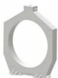

Quick Start Manual
Trip Characteristics
Standard IEC 60947-2 annex M indicates the operating characteristic for a non-time-delay type in table B.1 in B.4.2.4.1 in standard IEC 60947-2 annex M. CBRs having IΔn = 30 mA shall be of the non-time-delay type. If the trip time is set at '0' sec, then for 5 IΔn & 10 IΔn, the tripping time will be < 40 ms for all current ranges.
| Earth Leakage Current IΔn 2IΔn | 5IΔn | 1 | 10IΔn2 | |
| Maximum Break Time | 0.3 0.15 | 0.04 0.04 | ||
| 1) For CBRs having I n < 30 mA, 0.25 A may be used as an alternative to 5I n | ||||
| 2) 0.5 A if 0.25 A is used | ||||

For CBR's having limiting non-actuating time of 0.06 s the operating characteristic is given in table B.2. in B.4.2.4.1 in standard IEC 60947-2 annex M.
| Earth Leakage Current IΔn 2IΔn | 5IΔn | 1 | 10IΔn2 | |
| Maximum Break Time | 0.5 0.2 | 0.15 0.15 |


Trip Characteristics for t ≥ 0.15s
EN 60947-2:2003
B.4.2.4.2.2 Operating characteristic for CBR's having a limiting non-actuating time higher than 0.06 s declared by ENTES. The maximum break time at IΔn, 2 IΔn, 5 IΔn, and 10 IΔn.
| Earth Leakage Current Trip setting | Maximum Break Time | |||
| 1Δn 21Δn | 51Δn | 1 | 101Δn2 | |
| 0.15 s 0.5 0.25 0.25 0.25 | ||||
| 0.25 s 0.5 0.35 0.35 0.35 | ||||
| 0.5 s 0.6 0.6 0.6 0.6 | ||||
| 0.8 s 0.9 0.9 0.9 0.9 | ||||
| 1 s 1.1 1.1 1.1 1.1 | ||||
| 2.5 s 2.6 2.6 2.6 2.6 | ||||
| 5 s 5.1 5.1 5.1 5.1 | ||||
| 10 s 10.1 10.1 10.1 10.1 | ||||
Features
-
Wide leakage current adjustment range
-
Adjustable earth leakage trip time
-
Instantaneous trip (for details refer trip characteristics)
-
"Test Feature" to check product functionality
-
"Manual Reset Feature" with reset buton
-
Remote resetting
-
1C/O+1NO relay output
-
LED indications for all failures
-
Wide auxiliary supply voltage range
-
DIN rail mounting
-
Easy to install
-
Compact size
Recommendations
It is recommended to use CBCT's as mentioned in the table, to ensure the trip
current accuracy.
Caution
- Always follow instructions stated in this quick start manual.
2.Before installation, ensure that specifications compatible with intended
application.
-
Installation must be done by a successful electrician.
-
Suitable dampers must be provided in case of over-vibration during installation.
-
Automation and control devices must be installed so
that they are protected against any risk of involuntary
actuation.
6.Disconnect the power before working on the device.
Terminal Details

Use Cu Wire of 60/75°C only
Notes
-
Since the innovation of the product is a regular process, we reserve the right to change all its features without prior notice.
-
The factory settings of the device are set to 30mA trip and instantaneous delay.
These settings can be adjusted as needed by the installation. A seal is supplied allowing the user to secure the clear window and hence prevent any unnecessary adjustment of the settings.
-
To comply with regulations, it is recommended that the device should be tested periodically to ensure correct operation.
-
In case of excess harmonics power transmission cables have more leakage because of low impedance offered by cable capacitance, IΔn setting need to keep at higher level.
Functional Description
Earth Leakage Protection
- Leakage current is detected through core balance current transformer. - When earth leakage current exceeds the set value of trip current, for the trip time which is adjustable with the trimpots on the front panel, trip occurs. - For details refer trip characteristics. - The Red LED "EL" indicates the presence of Earth Leakage.
CBCT Connections
All main primary conductors shall pass through the core area of CBCT. Use shielded wires for secondary terminal connections to B1 & B2. Connect the shield to the Y2 terminal of device, which is circuit ground of the device. The CT wires should be placed adequately away from high current carrying conductors or source of strong magnetic field to avoid noise pickup. The Earth Leakage Relay also verifies CT connection. If CT winding is open, red LED*EL" blinks.
Functional Diagram

Test / Reset
Press & hold "tst/rst switch" for 1sec. The product will change its state from "healthy" to "Trip (Test)" and vice versa "Reset".
Remote Test / Reset
For "remote testing & resetting", connect an external push button/switch between Y1 and Y2. For test sequence, press and hold the external push button switch for 1sec.
Auto/ Reset
For the ELR-30-A, product will automatically reset itself after 4 earth leakage fault in 15min. Reset count is cleared after 1 hour of healthy condition, supply interruption or pressing of the test /reset switch.
Overall Dimensions and Mounting Details

Front Face
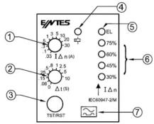
-
Trimpot for "earth leakage current" setting
-
Trimpot for "trip time" setting 3. "Text/Reset Function" button
-
Test/Reset Function button
-
"Power ON" LED indication
-
"Earth leakage fault" or "CT open" LED indication
-
Bar graph for "earh leakage fault" indication
-
"Type A" indication
Notes
- For CT connections use shielded wire and connect shield to Y2 terminal.
- For single phase applications, only phase and neutral cables need to be passed through CBCT.
- Do not pass ground conductor through CBCT connected to earth
leakage relay. - All conductors to be protected must pass through CBCT.
- Do not apply supply voltage at CT and switch terminal.
- Connect the wires between CBCT and ELR with respect to B1 & B2. Wire
gauge should be as mentioned under "Terminal Details" - This device satisfies the requirements for Type A devices which provides protection against leakage current in systems where alternating and direct current are used together.
| ELR Operating condition | Contact Position | |
| 1 NO (PSO/Fail Safe) | 1 CO (PSO/Fail Safe) | |
| No Auxiliary | ||
| Healthy / Rest State | ||
| Trip State | ||
Centre the cables within the toroid
![graph TD A["Wire topology with toroidal 0 ≥ 2 x Total Cable 0"] --> B["Cable Routing Details"] B --> C["Wire topology with toroidal 0 x Toroidal B"] C --> D["Cable Routing Details"]](/content/2026/05/941928/images/b1cdabbc2167f17ba9c89f2341922475a472288adc492b318d564ed4fca003c8.jpg)
| CBCT | SIZE | WEIGHT (in gr.) | A | B | C | D | E |
| CBCT-70 | 70 | 240 | 20 | 109 | 133 | 27 | 60 |
| CBCT-92 | 92 | 250 | 20 | 132 | 155 | 27 | 73 |
| CBCT-120 | 120 | 255 | 20 | 153 | 176 | 27 | 73 |
| CBCT-210 | 210 | 280 | 20.5 | 250 | 282 | 28 | 128 |
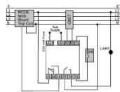
Connection Diagram
FAIL SAFE MODE (CONTACTOR)
NON—FAIL SAFE MODE (SHUNT TRIP COIL)
FAIL SAFE MODE (CONTACTOR)

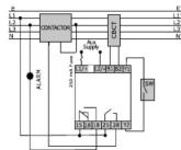
NON-FAIL SAFE MODE (CONTACTOR)
FAIL SAFE MODE (UV TRIP COIL)
SINGLE PHASE APPLICATION
NON-FAIL SAFE MODE (UV TRIP COIL)

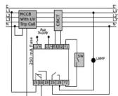

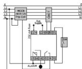
Conformity to Standarts EMC
| Harmonic Current Emission IEC 61000-3-2 Class A | |
| Voltage Flicker and Fluctuations IEC 61000-3-3 Class A | |
| ESD IEC 61000-4-2 Level II | |
| Radiated Susceptibility IEC 61000-4-3 Level III | “Criteria B” |
| Electrical Fast Transients IEC 61000-4-4 Level IV | |
| Surge | IEC 61000-4-5 Level IV for AC & Level I for DC Products |
| Conducted Susceptibility | IEC 61000-4-6 Level III for AC |
| Voltage Dips and Interruptions (AC) | IEC 61000-4-11Level I, II, III, IV, V, VI & VIII |
| Voltage Dips and Interruptions (DC) | 50% for 50mSec @ Nominal Voltage 15V DC |
| Conducted Emission | CISPR 11Class A |
| Raiated Emission | CISPR 11Class A |
Security
| Test Voltage Between I/P & O/P | IEC 60947-5-1 / UL 508 | 2 kV |
| Test Voltage Between all Terminals & Enclosure | IEC 60947-5-1 / UL 508 | 2.5 kV |
| Over Voltage Category IEC 60947-1 | IV | |
| Impluse Voltage Between I/P & O/P | IEC 60947-5-1 Level 4kV | |
| Single Fault | IEC 61010-1 | |
| Insulation Resistance | UL 508 | >50kOhm |
| Leakage Current | UL 508 | <3.5 mA |
Environmental
| Cold Heat | IEC 60068-2-1 | |
| Dry heat | IEC 60068-2-2 | |
| Vibration | IEC 60068-2-6 5g(10-50 Hz) | |
| Repetitive Shock | IEC 60068-2-27 | 40 g, 6 ms |
| Non-repetitive Shock | IEC 60068-2-27 | 30 g, 15 ms |
Note: As per IEC60947-2 (B.4.2.2) The minimum value of rated residual non operating current is 0.5 lΔn.

Ön Yüz

FAIL SAFE MOD (KONTAKTÖR)

NON-FAIL SAFE MOD (KONTAKTÖR)
FAIL SAFE MOD
(DÜŞÜK GERİLİM AÇMA BOBİNİ)
TEK FAZLI UYGULAMA
NON-FAIL SAFE MOD (DÜŞÜK GERİLİM AÇMA BOBİNİ)


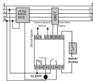
Standartlar
Brand : ENTES
Model : ELR-30-M
Category : Electrical protection relay