
DS-TD10M-1 - Camera Hikvision - Free user manual and instructions
Find the device manual for free DS-TD10M-1 Hikvision in PDF.


| Product Type | Multi-Target Speed-Measuring Radar |
| Brand | Hikvision |
| Model | DS-TD10M-1 |
| Installation Height | 6 m (recommended) |
| Down Tilt Angle | 10° (factory scale on mount) |
| Trigger Distance | 28 m (configurable) |
| Maximum Lanes | 4 |
| Communication Interface | RS-485 serial (3-wire: D+, D-, GND) |
| Baud Rate | 115200 |
| Power Supply | 12 VDC (do not use 220 VAC) |
| Operating Temperature | Not specified in manual, typical for outdoor radar: -40°C to +70°C (estimated) |
| Ingress Protection | Not specified, likely IP66 (common for outdoor radar) |
| Detection Range | Up to 28 m trigger distance, further detection for speed measurement |
| Speed Measurement Range | Single byte: < 255 km/h; Double byte: ≥ 255 km/h |
| Wireless Connectivity | WiFi for debugging (default password: RADAR2019) |
| Software Compatibility | Windows XP/Vista/7/8 (64-bit recommended) |
| Included Accessories | Mounting hoop, debugging software on CD |
| Dimensions | Not specified, typical pole-mount radar approx. 300×200×100 mm (estimated) |
| Weight | Not specified, typically 1-2 kg (estimated) |
Frequently Asked Questions - DS-TD10M-1 Hikvision
User questions about DS-TD10M-1 Hikvision
0 question about this device. Answer the ones you know or ask your own.
Ask a new question about this device
Download the instructions for your Camera in PDF format for free! Find your manual DS-TD10M-1 - Hikvision and take your electronic device back in hand. On this page are published all the documents necessary for the use of your device. DS-TD10M-1 by Hikvision.
USER MANUAL DS-TD10M-1 Hikvision
Mul-Target Speed-Measuring Radar
User Debugging Manual
© 2019 Hangzhou Hikvision Digital Technology Co., Ltd. All rights reserved.
ALL RIGHTS RESERVED.
This Manual is the property of Hangzhou Hikvision Digital Technology Co., Ltd. or its aliases (hereinaer referred to as “Hikvision”), and it cannot be reproduced, changed, translated, or distributed, parally or wholly, by any means, without the prior written permission of Hikvision. Unless otherwise expressly stated herein, Hikvision does not make any warranties, guarantees or representations, express or implied, regarding to the Manual, any information contained herein.
About this Manual
The Manual includes instrucons for using and managing the Product. Pictures, charts, images and all other informaon hereinaer are for descripon and explanaon only. The informaon contained in the Manual is subject to change, without noce, due to rmware updates or other reasons. Please nd the latest version of this Manual at the Hikvision website (hps://www.hikvision.com/en/).
Please use this Manual with the guidance and assistance of professionals trained in supporting the Product.
Trademarks Acknowledgement
- HIKVISION and other Hikvision's trademarks and logos are the properes of Hikvision in various jurisdicons.
● Other trademarks and logos menoned are the properes of their respective owners.
Legal Disclaimer
- TO THE MAXIMUM EXTENT PERMITTED BY APPLICABLE LAW, THIS MANUAL AND THE PRODUCT DESCRIBED, WITH ITS HARDWARE, SOFTWARE AND FIRMWARE, ARE PROVIDED "AS IS" AND "WITH ALL FAULTS AND ERRORS". HIKVISION MAKES NO WARRANTIES, EXPRESS OR IMPLIED, INCLUDING WITHOUT LIMITATION, MERCHANTABILITY, SATISFACTORY QUALITY, OR FITNESS FOR A PARTICULAR PURPOSE. THE USE OF THE PRODUCT BY YOU IS AT YOUR OWN RISK. IN NO EVENT WILL HIKVISION BE LIABLE TO YOU FOR ANY SPECIAL, CONSEQUENTIAL, INCIDENTAL, OR INDIRECT DAMAGES, INCLUDING, AMONG OTHERS, DAMAGES FOR LOSS OF BUSINESS PROFITS, BUSINESS INTERRUPTION, OR LOSS OF DATA, CORRUPTION OF SYSTEMS, OR LOSS OF DOCUMENTATION, WHETHER BASED ON BREACH OF CONTRACT, TORT (INCLUDING NEGLIGENCE), PRODUCT LIABILITY, OR OTHERWISE, IN CONNECTION WITH THE USE OF THE PRODUCT, EVEN IF HIKVISION HAS BEEN ADVISED OF THE POSSIBILITY OF SUCH DAMAGES OR LOSS.
- YOU ACKNOWLEDGE THAT THE NATURE OF INTERNET PROVIDES FOR INHERENT SECURITY RISKS, AND HIKVISION SHALL NOT TAKE ANY RESPONSIBILITIES FOR ABNORMAL OPERATION, PRIVACY LEAKAGE OR OTHER DAMAGES RESULTING FROM CYBER-ATTACK, HACKER ATTACK, VIRUS INSPECTION, OR OTHER INTERNET SECURITY RISKS; HOWEVER, HIKVISION WILL PROVIDE TIMELY TECHNICAL SUPPORT IF REQUIRED.
YOU AGREE TO USE THIS PRODUCT IN COMPLIANCE WITH ALL APPLICABLE LAWS, AND YOU ARE SOLELY RESPONSIBLE FOR ENSURING THAT YOUR USE CONFORMS TO THE APPLICABLE LAW. ESPECIALLY, YOU ARE RESPONSIBLE, FOR USING THIS PRODUCT IN A MANNER THAT DOES NOT INFRINGE ON THE RIGHTS OF THIRD PARTIES, INCLUDING WITHOUT LIMITATION, RIGHTS OF PUBLICITY, INTELLECTUAL PROPERTY RIGHTS, OR DATA PROTECTION AND OTHER PRIVACY RIGHTS. YOU SHALL NOT USE THIS PRODUCT FOR ANY PROHIBITED END-USES,
INCLUDING THE DEVELOPMENT OR PRODUCTION OF WEAPONS OF MASS DESTRUCTION, THE DEVELOPMENT OR PRODUCTION OF CHEMICAL OR BIOLOGICAL WEAPONS, ANY ACTIVITIES IN THE CONTEXT RELATED TO ANY NUCLEAR EXPLOSIVE OR UNSAFE NUCLEAR FUEL-CYCLE, OR IN SUPPORT OF HUMAN RIGHTS ABUSES.
IN THE EVENT OF ANY CONFLICTS BETWEEN THIS MANUAL AND THE APPLICABLE LAW, THE LATER PREVAILS.
Symbol Convenons
The symbols that may be found in this document are dened as follows.
| Symbol | Descripon |
 | Provides additional informaon to emphasize or supplement important points of the main text. |
 | Indicates a potenally hazardous situaon, which if not avoided, could result in equipment damage, data loss, performance degradaon, or unexpected results. |
 | Indicates a hazard with a high level of risk, which if not avoided, will result in death or serious injury. |
TABLE OF CONTENTS
Chapter 1 Radar Installaon .... 4
1.1 Installaon Parameters ....4
1.2 Install Radar....4
1.3 Wire Radar ....5
Chapter 2 Operaon via Radar Debugging Soware....7
2.1 Overview ....7
2.2 Running Environment....7
2.3 Install Soware....7
2.4 Operate via Soware....8
2.4.1 Connect Radar....11
2.4.2 Debug Radar....12
Chapter 3 FAQ....14
Chapter 1 Radar Installaon
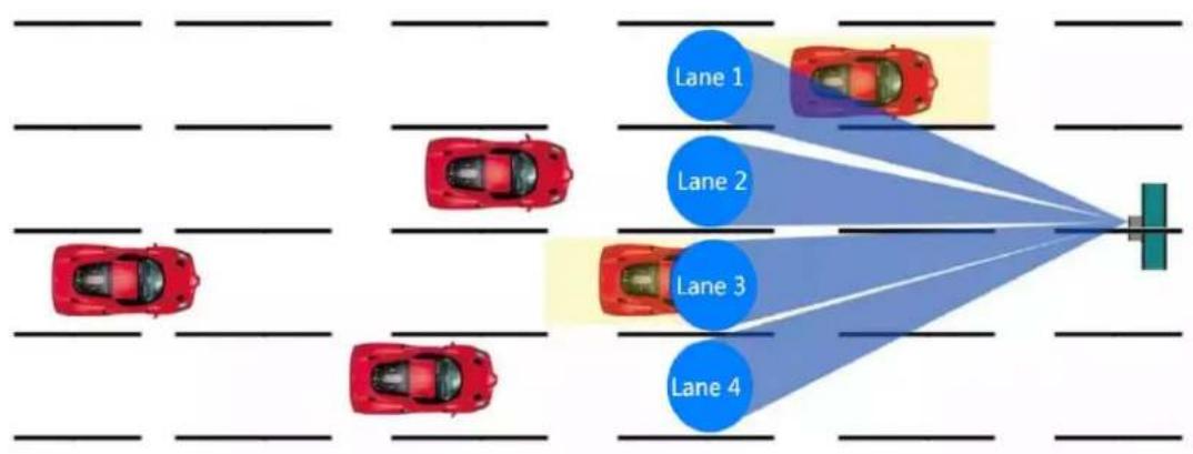
DS-TD10M-1 radar is usually installed in the middle posion of gantry and L-shaped pole, as shown in Figure 1-1.
flowchart
graph TD
    A["Top Row: Cars"] --> B["Lane 1"]
    A --> C["Lane 2"]
    A --> D["Lane 3"]
    A --> E["Lane 4"]
    B --> F["Top Column"]
    C --> F
    D --> F
    E --> F
Figure 1-1 Radar Installaon
1.1 Installaon Parameters
• Installaon height: 6 m
- Downlt: 10^
● Trigger distance: 28 m
1.2 Install Radar
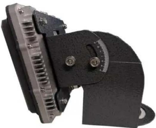
The radar installaon angle is determined by the scale (10°) on the DS-TD10M-1 radar mount.
Steps:
- Fix the radar on the gantry or crossbar with hoop.
- Connect radar to the debugging soware.
- Check the actual track of passing vehicle to adjust the downlt of the radar.
- Observe the moving track of target to conrm the most appropriate trigger distance, which should be set at the middle posion of track.
- Fasten the radar adjustment screws aer the angle is set.
natural_image
Close-up of a mechanical component with metallic and black parts, no visible text or symbolsFigure 1-2 Radar Installaon Angle
1.3 Wire Radar

WARNING
The radar is powered by 12 VDC, and it will be burnt if powered by 220 VAC.
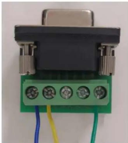
- The radar and capture camera communicate via RS-485 serial port with 3 signal lines, among which the blue one indicates D+, yellow indicates D-, and green indicates DGND. The radar should be connected to the camera based on ideners. Set the radar baud rate as 115200 when connecng the radar with camera.
- Use USB to RS-485 switch line or USB to RS-232 switch line and RS-232 to RS-485 conversion module to connect the radar to the computer. Generally, the DB9 header of RS-485 serial port denes pin 1 as D+, pin 2 as D-, and pin 5 as GND. All the 3 lines should be connected properly, as shown in Figure 1-3.

NOTE
The radar outputs signal via RS-485 serial line. Connecng with RS-232 serial line will not work out.
natural_image
Close-up of a black electronic component with four green terminal blocks and metallic connectors, connected to blue and yellow wires (no text or symbols visible)Figure 1-3 RS-485 DB9 Header Connecon
Chapter 2 Operaon via Radar Debugging Soware
2.1 Overview
This soware is the debugging soware for DS-TD10M-1 radar. It is used to conjure parameters of the radar for installaon, debugging, and troubleshooting. The soware installaon package is included in the product CD.
2.2 Running Environment
- Soware environment: It is applicable to Windows XP\Vista\7\8. Install Microsoft.NET FrameWork4.0 or above version (the kit is included in the installaon package) to the computer. It is recommended to use 64-bit version of windows 7.
- Hardware environment: It is required that the computer should be equipped with 2.0 GHz CPU, 2 GB memory, and 1 GB video memory. It is recommended to use a separate graphics card for beer display results.
2.3 Install Soware
Steps:
- Double click the setup.exe le in the installaon package.

If Microso.NET Framework does not exist in the computer, it will be installed automacally.
- Install the debugging soware according to the installation wizard, as shown in Figure 2-1.
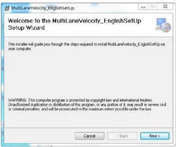
Figure 2-1 Installaon Wizard
- Click Next and then select an installaon path, as shown in Figure 2-2.
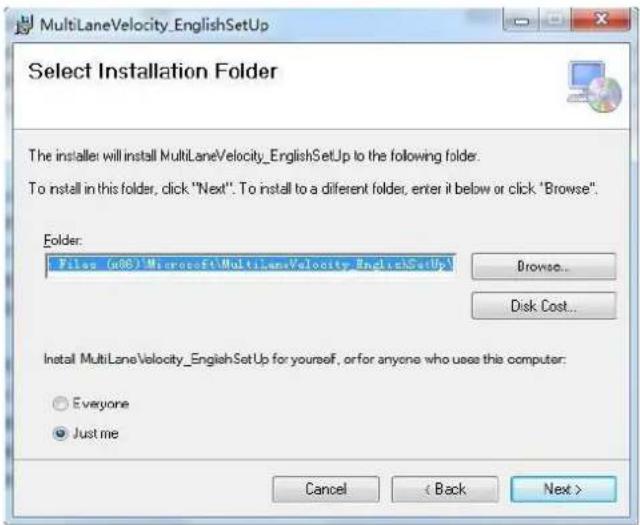
Figure 2-2 Select Installaon Path
- Click Next to connue. The setup wizard will complete the soware installaon automacally, as shown in Figure 2-3.
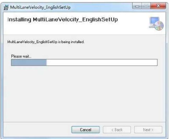
Figure 2-3 Install Soware
- Click OK, and a shortcut named MulLaneVelocity.exe will be generated on the Windows desktop.
- Double click the shortcut icon to run it.
2.4 Operate via Soware
Before you start:
Connect the radar to the computer properly.
There are three working modes of the soware: debug mode, test velocity mode, and measure mode. Switch the radar to dierent working modes via the soware.
The soware enters the interface as shown in Figure 2-4 aer running.
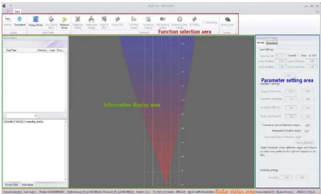
Figure 2-4 Debugging Soware Interface
The interface contains Funcon Selecon Area, Informaon Display Area, Parameter Seng Area, and Radar Status Area.
● Funcon Selecon Area includes mulple funcons to choose, such as device conncon, debug mode, parameters reading and burning ash. Specific denions are as follows.
Device Connecon: Click Connect and select a communicaon mode to enable the communicaon between soware and radar.
Device Disconnecon: Click Disconnect to disable the communicaon between soware and radar.
➢ Debug Mode: Only in this mode can radar parameters and WiFi password be edited.
Test Velocity Mode: The normal mode of speed detection. In this mode, parameters seng and reading are not allowed.
➢ Measure Mode: Measure mode is only required for measuring detection.
Single Byte Seng: If the detecon speed is lower than 255 km/h, select single byte seng.
Double Byte Seng: If the detecon speed is higher than 255 km/h, select double byte seng.
➢ Angle of Pitch: Read and view the pitch angle of radar.
Product SN.: Read and view the serial number of radar product.
Soware Version: Read and view the current radar version.
Parameters Reading: Read the current road informaon and installaon parameters.
WiFi Password Seng: Edit the current WiFi password connected to the radar.
Restore Factory Setng: Restore the parameters and road informaon to default status.
ID Seng: Set dierent frequency points to avoid mutual interference.
Track Shows: Show the real-me moving track of target when selected.
Burning Flash: When the radar does not connect to the debugging soware, click Burning Flash to upgrade the current version of soware.
- Informaon Display Area displays the detecon speed, lane information, direcon and real-me picture simulaon of the current target.
● Parameter Setng Area contains General Sengs and Advanced Setngs. Lane Seng, Installaon Seng and Sensitivity Seng can be congured in this area.
General Sengs
- Lane Seng: No more than 4 lanes is allowed. Three direction modes (Towards, Away and Both) can be selected. The Lane Width should be set in accordance with actual road width.
- Trigger Distance: The radar will report the speed information of target which arrives at this posion.
- Installaon Height: Set in accordance with actual installaon height.
- Horizontal Shi: Set in accordance with the deviaon of the radar to the horizontal center.
Angle Adjustment: Make adjustments based on the target moving track detected by the radar. - Sensitivity Seing: The detecon sensitivity of radar. The higher the value is, the lower the sensitivity will be.
Advanced Sengs
The debugging soware can be switched to the advanced seng interface only in debug mode. In this interface, the velocity correcon value and the trigger distance correcon value of each lane can be set, as shown in Figure 2-5.
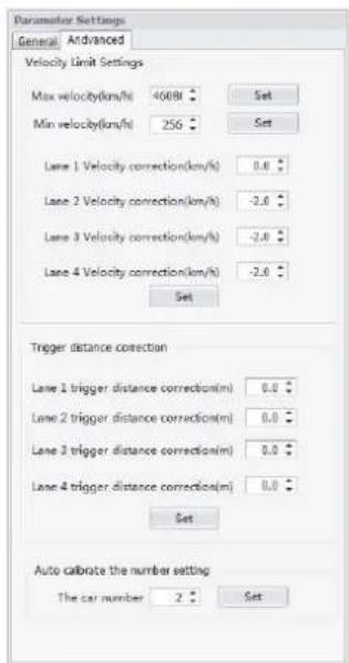
Figure 2-5 Advanced Sengs Interface
- Radar Status Area displays the current status of radar, including soware version, product serial number and current seng parameters.
2.4.1 Connect Radar
Steps:
- Select Device Connect, and the conncon seng dialog box will pop up. As shown in Figure 2-6, there are two conncon methods: WIFI conncon and Serial conncon.

NOTE
The initial default conncon method is serial conncon. All available serial ports of the device will be listed and the user can select the port number to connect device through the drop-down list box.
- Select Baud as 115200, Data as 8, Stop as 1, and Parity as none.
- Click OK.
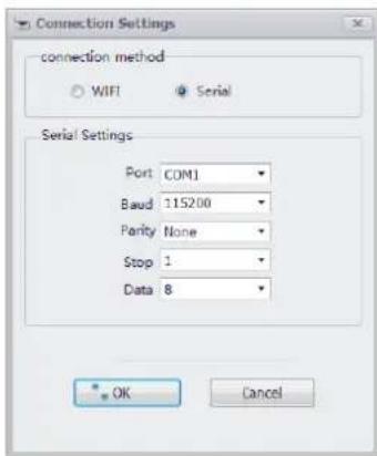
Figure 2-6 Device Connecon Sengs
- (Oponal) You can also select the conncon method as WIFI conncon. The computer must have been connected to the radar via WiFi in advance. Click OK and the device will connect automacally.
During the device conncon process, the soware will automatically read the soware version, device number and current seng parameters. These parameters will be displayed in the Radar Status Area at the boom of the interface.
i NOTE
The name of radar is dened as RAD + 11-digit serial No., and the original password is RADAR2019.
2.4.2 Debug Radar
Aer road informaon (number of lanes and lane width) and installaon parameters (trigger distance and installaon height) are set, view the real-me vehicle status displaying window to check whether the vehicle is in the corresponding lane or not. Set the angle correcon and horizontal shi as required to ensure that the target vehicle is in the corresponding lane.
The above parameters should be set according to the actual installaon condions. The horizontal shi value is negave to the le and posive to the right, and the posive center of all lanes are set as the value of 0. If the radar is installed at the le lane, set the horizontal shi as a negave value (the deviaon value of distance from the center of all lanes). If the radar is installed at the right lane, set the horizontal shi as a posive value, as shown in Figure 2-7.
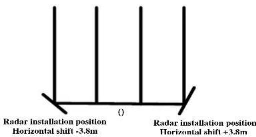
Figure 2-7 Horizontal Shi Sengs
Firstly, the moving track should be straight and the initial appearance distance should be greater than the trigger distance. Otherwise, some of the targets will be undetectable.
For instance, if the trigger distance of Towards Direcon is set as 28 meters, the appearance distance should be set as about 35 meters.
Secondly, it is necessary to ensure that the detected lane corresponds to the actual lane.
Otherwise the lane number will be inconsistent with the data reported. Adjust the value of pitch oset based on the moving track shi.
Aer debugging, click Measure Mode and the radar will run normally.
Chapter 3 FAQ
- Connecng to soware failed.
- Check whether the computer has been installed a serial port driver, and then view the port number in device management module.
- If the radar is connected to the software, the serial port parameters are set as follows: baud rate 115200, data bit 8, stop bit 1, parity none.
- Connect radar cables to RS-485 serial port, with the blue one connects to pin 1 of DB9, the yellow one connects to pin 2 and the green one connects to pin 5.
- Detecng targets failed.
- Check radar parameters and adjust the pitch angle to enable the radar beam to cover the trigger posion.
For instance, if the trigger distance is set as 28 meters but the pitch angle is over downward, then only area within 20 meters can be covered. In this case, the radar won't be triggered when a vehicle passing through the set position. Adjust the pitch angle to make it cover a range of 28 meters.
- Check camera RS-485 serial port, baud rate, radar type, and other parameters. It is recommended to use USB with UT891 or UT890 chip to RS-485 switch line, which is user friendly and boasts of a low bit error rate.

See Far, Go Further
- Mul-Target Speed-Measuring Radar
- ALL RIGHTS RESERVED.
- About this Manual
- Trademarks Acknowledgement
- Legal Disclaimer
- Symbol Convenons
- TABLE OF CONTENTS
- Chapter 1 Radar Installaon .... 4
- Chapter 2 Operaon via Radar Debugging Soware....7
- Chapter 3 FAQ....14
- Chapter 1 Radar Installaon
- Installaon Parameters
- Install Radar
- Steps:
- Wire Radar
- WARNING
- NOTE
- Chapter 2 Operaon via Radar Debugging Soware
- Overview
- Running Environment
- Install Soware
- Operate via Soware
- General Sengs
- Advanced Sengs
- Connect Radar
- i NOTE
- Debug Radar
- Chapter 3 FAQ
- - Connecng to soware failed.
- - Detecng targets failed.
Brand : Hikvision
Model : DS-TD10M-1
Category : Camera