BSA-500 - Uncategorized Maruyama - Free user manual and instructions
Find the device manual for free BSA-500 Maruyama in PDF.


| Product Type | Backpack Sprayer |
| Brand | Maruyama |
| Model | BSA-500 |
| Tank Capacity | 5 gallons (18.9 liters) |
| Operating Pressure | 30-90 psi (2.1-6.2 bar) |
| Pump Type | Piston pump |
| Dimensions (L x W x H) | 19 x 14 x 24 inches (48 x 36 x 61 cm) |
| Weight (empty) | 12.5 lbs (5.7 kg) |
| Power Source | Manual (hand lever) or battery (optional) |
| Hose Length | 60 inches (152 cm) |
| Nozzle Type | Adjustable brass nozzle |
| Spray Pattern | Fine mist to solid stream |
| Application | Lawn care, pest control, weed control |
| Material | High-density polyethylene (HDPE) tank |
| Seals | Viton for chemical resistance |
| Strap | Adjustable padded shoulder straps |
| Maintenance | Rinse after use, lubricate pump seals |
| Safety | Pressure relief valve, use PPE |
| Warranty | 2 years limited warranty |
| Repairability | Replacement parts available online |
Frequently Asked Questions - BSA-500 Maruyama
User questions about BSA-500 Maruyama
0 question about this device. Answer the ones you know or ask your own.
Ask a new question about this device
Download the instructions for your Uncategorized in PDF format for free! Find your manual BSA-500 - Maruyama and take your electronic device back in hand. On this page are published all the documents necessary for the use of your device. BSA-500 by Maruyama.
USER MANUAL BSA-500 Maruyama
Be sure to read before use.
Introduction
Thank you for purchasing a Maruyama product. This Operation Manual explains the correct handling of the product and how you can easily inspect and care for it, so that you can carry out your work safely and comfortably using the machine.
Before using the product, read this manual carefully and understand the contents fully so that the product will continue to demonstrate excellent performance.
After reading this manual, keep it in a safe place and reference it every time you have a question. Please note that information contained in this manual may not exactly match the product you purchased due to specification changes of the product, etc.
If you have any feedback on this product, please contact the Maruyama dealer or sales office near you.
■ Scope of Use
- This product is designed primarily for spraying chemicals over paddy fields and crop fields. Maruyama shall assume no responsibility for any accident caused by using the product outside the foregoing scope of use or accident arising from an unauthorized modification or disassembly.
■ Precautions
- The precautions contained in this manual and warning labels bearing ⚠️ you see on the machine provide important items that may cause injury if neglected. Read these precautions and labels carefully and be sure to follow the instructions.
In this Operation Manual, particularly important handling precautions are denoted as follows:
Danger --- Failure to follow this instruction will lead to death or serious injury.
Warning --- Failure to follow this instruction may lead to death or serious injury.
Caution --- Failure to follow this instruction may lead to injury.
Caution --- Failure to follow this instruction may lead to machine damage.
■ Lending the Machine to a Third Party
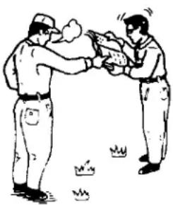
- Pass this Operation Manual/Safety Manual together with the machine and instruct the user to carefully read these manuals to understand the contents and get the hang of handling the machine, so that your friendly gesture will not turn into a tragedy. Same thing goes with your family. In particular, spend time explaining the prohibited items.
natural_image
Two men in military-style uniforms exchanging a large object, with small firecrackers nearby (no text or symbols)■ International Units
- This Operation Manual uses the units based on the new measuring system. Carefully read the table below to understand the conversion values before use.
Conversion Table
| Item | Unit indication under new measuring system | Conversion | Conventional unit indication | Remarks |
| Area | [m2] (square meters) [a] (are) [ha] (hectare) | 10000 [m2] = 1 [ha] = 100 [a] = 10 tanbu = 3,000 tsubo | [a] (are) [ha] (hectare) Tsubo, chobu, tanbu | *[1] |
| Rotational speed | [rpm] (revolutions per minute) [min-1] (per minute) | 1 [min-1] = 1 [rpm] | [rpm] | *[2] |
| Force | [N] (Newton) | 9.8 [N] = 1 [kgf] | [kgf] (weight kilogram) | |
| Moment of force | [N·m] (Newton meter) | 9.8 [N·m] = 1 [kgf·m] | [kgf·m] | |
| Pressure | [Pa] (Pascal) | 0.98 [MPa] = 10 [kgf/cm2] 9.8 [Pa] = 1 [mmH2O] | [kgf/cm2] [mmH2O] | |
| Work ratio/ drive power | [W] (watt) | 735.5 [W] = 1 [PS] 9.8 [W] = 1 [kgf·m/s] | [PS] [kgf·m/s] |
* Notes
[1] [a] and [ha] may be used to indicate land areas.
[2] The number of revolutions per unit time is indicated as “rotational speed” not as “revolutions.”
Specifications
In this Operation Manual, products of different specifications are indicted as follows. Confirm the specification of the product you purchased to make sure you are referring to the correct product. All explanations apply to the BSA-500S-1, as a rule, and any difference in handling from the BSA-500S-1 is explained by additional text every time.
● Hydraulic boom, up/down & open/close type .... Specification J
- Specifications by tread ....Specification S (Tread: 1200 mm)
Specification A (Tread: 1320 mm)
Specification E (Tread: 1500 mm)
Specification M (Tread:1800 mm)
● Super-high clearance type (Effective ground clearance 1100 mm) .... Q specification
Table of Contents
1 For Safe Work....5
2 Name of Each Part....7
3 Main Specifications....10
4 Handling of Warning Labels 12
5 Name and Function of Each Device 16
6 How to Travel/Transport....24
7 Pest Control Work....28
8 Maintenance....35
9 Piping Diagram....46
10 Causes of Failures and Remedial Actions 47
1
For Safe Work
The precautions you must observe to ensure safe work are explained below.
Other precautions are found in the main text, accompanied by ⚠ Danger, ⚠ Warning, ⚠ Caution and Caution.
Use this machine at an inclination angle of within 5^ except when entering a field or installing the machine on a truck.
(1) Overview
Carefully read the "Operation Manual (and operation manual of each option installed)," "Safety Manual" and instruction of the agrichemical used, to carry out work correctly and safely.
Caution
- Do not put objects underneath the booms while the machine is parked or in storage. The booms may drop and damage the objects.
[1] When carrying out work, be sure to wear protective gears appropriate for each work (helmet, mask and gloves) and proper clothes.
[2] Before inspecting/servicing or repairing the machine, stop the engine on flat ground, apply the parking brake and remove the ignition key. Failure to do so may cause the machine to suddenly move, resulting in an accident.
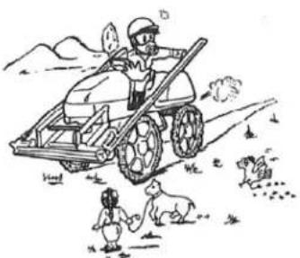
[3] Keep non-operators (especially children) away from the area where pest control work is performed. Failure to do so may lead to an accident.
[4] Exercise due caution not to pollute water supply systems, rivers, ponds, lakes, etc.
[5] Never refuel near a fire source as it may cause fire. Refueling while smoking is strictly prohibited.
natural_image
Illustration of a farmer operating a tractor with two children and dogs in a field (no text or symbols)(2) Items to Note before Operation
[1] Carefully read the Operation Manual and become familiar with the machine operation.
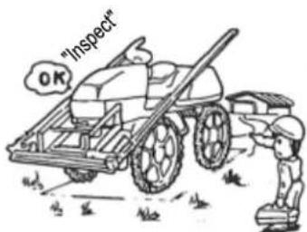
[2] Apply the parking brake on flat ground and be sure to perform startup inspection to prevent problems during pest control work.
Maintenance, P. 35
[3] Wipe clean all spilled fuel or oil. If not, fire may occur.
[4] Dust, fuel or mud attached or deposited on the wires, muffler and engine area may cause fire, so inspect and clean these areas before starting the day's work.
(3) Starting the Engine
[1] If the machine is operated indoors, exhaust gas will pollute the air and may cause gas poisoning. Open the windows and doors and provide sufficient exhaust ventilation.
[2] Before starting the engine, look around carefully and give a cue to others indicating that the machine "will start moving."
(4) Traveling
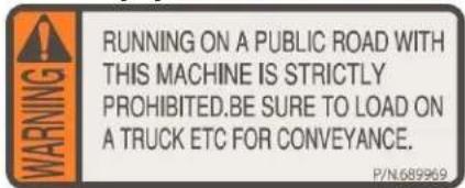
[1] This machine cannot travel on local road and must be carried on a truck, etc., to the field.
[2] This machine can carry only one person. No one except for the driver can ride the machine. Any consequence of the machine carrying a person or persons other than the driver will be the responsibility of the user.
[3] Do not drive at high speed, take off suddenly, accelerate rapidly, apply emergency braking or make a sharp turn unless necessary.
[4] Do not carry a load exceeding the maximum payload (reagent tank filled with water and attachments installed). Excessive loading will not only lead to machine damage, but it may also cause an accident.
(5) Entering/Exiting a Field (Refer to P. 28)
[1] Enter the field at low speed by orienting the machine vertically to the furrows.
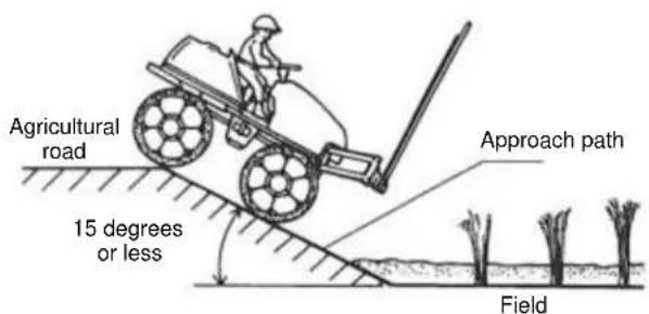
[2] If there are large height gaps or the approach path is soft, be sure to use footboards as you enter/exit the field. Failure to do so may cause the machine to tip over, creating a very dangerous situation.
[3] Maintain the approach path so that the inclination angle of approach to the field is kept within 15 degrees.
(6) Loading/Unloading to/from a Truck (Refer to P. 27)
[1] When loading the machine to a truck, empty the reagent tank and drive the machine head in. When unloading the machine, drive the machine slowly in reverse.
[2] Use a truck whose payload is 2,000 kg or more.
[3] Move the machine slowly using anti-slip footboards of sufficient strength, length and width (30 cm or more).
[4] Securely hook the footboards by leaving no height gap or misalignment on the load-carrying platform.
[5] If the engine of the machine stalls during loading or unloading, immediately step on the brake pedal and then gradually release the brake to lower the machine onto the road.
[6] Choose flat ground and load/unload the machine in the presence of/with guidance from the assistant.
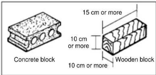
(7) Chocking the Tires
Prepare concrete blocks, wooden blocks or other objects that can be used to chock the tires so that the machine can be parked safely.
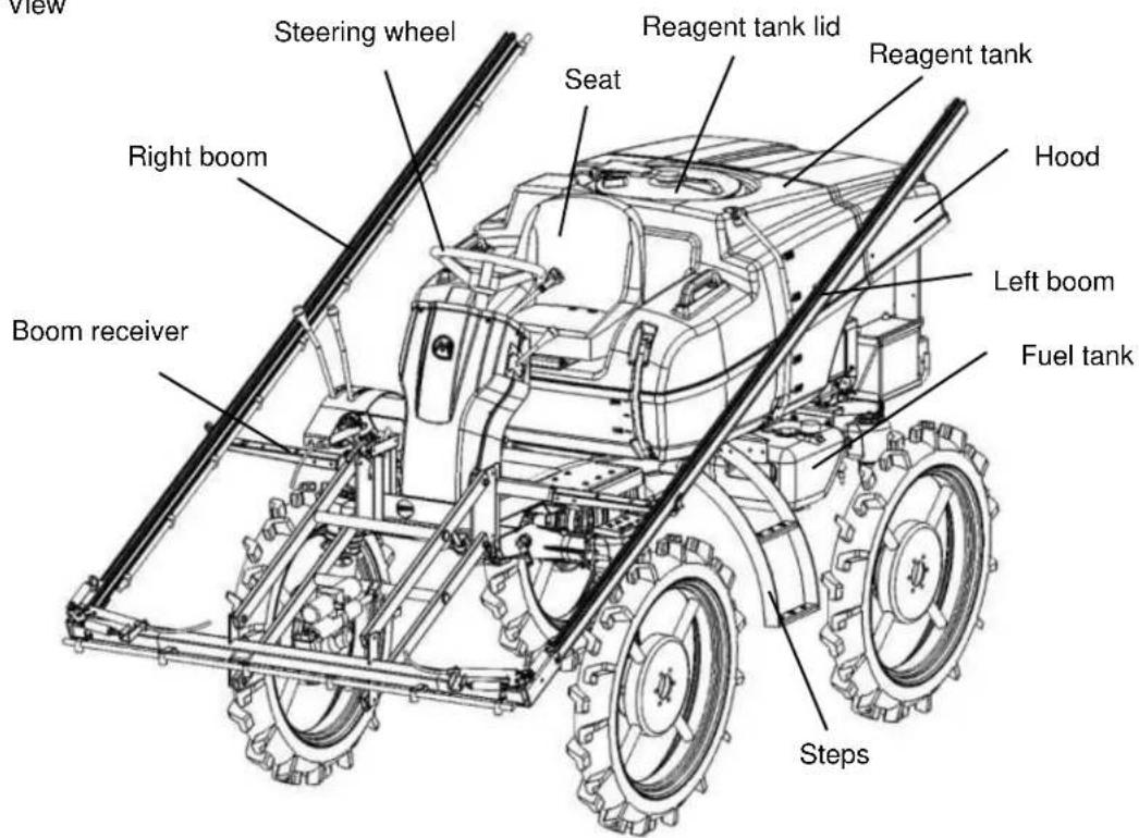
2 Name of Each Part
(1) External View
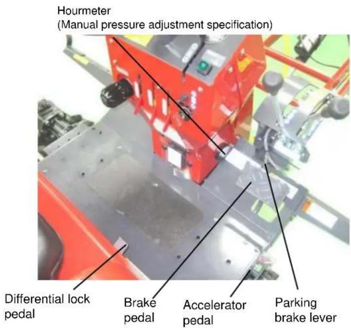
(2) Driving Devices
![[Manual Pressure Adjustment Specification] Speedometer Glow lamp Charge lamp Oil pressure lamp Steering wheel HST lever Water temperature warning lamp Pressure gauge Throttle lever Auxiliary shift lever Spray pump switch Key switch Spray cock Pressure adjustment dial Fuse box](/content/2026/05/941812/images/a6111599f2cfa0de2202eeb5e753850e793f3c1fdd79afe0bd4c44a3a953afdd.jpg)
[Manual Boom Open/Close Specification]
[Specification J (Hydraulic Boom Up/Down & Open/Close Specification)]
3 Main Specifications
| Name | BSA-500 | |||||||
| Category | S-1 | A-1 | E-1 | JS | JA | JE | ||
| Machine dimensions | Overall length | (mm) | 3360 | 3760 | ||||
| Overall width | (mm) | 1700 | 2170 | |||||
| Overall height | (mm) | 2065 | 2500 | |||||
| Wheelbase | (mm) | 1570 | ||||||
| Tread | (mm) | 1200 | 1320 | 1500 | 1200 | 1320 | 1500 | |
| Effective ground clearance | (mm) | 800 (axle hosing) | ||||||
| Minimum ground clearance | (mm) | 755 | ||||||
| Mass | (kg) | 780 | 795 | 800 | 860 | 875 | 880 | |
| Engine | Name | D722-E3B-SSMR-2 | ||||||
| Type | Water-cooled 4-cycle, 3-cylinder standing diesel engine | |||||||
| Total displacement | (L) | 0.719 | ||||||
| Rated output | (kW(PS)/rpm) | 10.7(14.5)/2900 | ||||||
| Fuel tank capacity | (L) | 20 | ||||||
| Starting method | Cell starter | |||||||
| Traveling gears | Type | 4WD·4WS | ||||||
| Steering system | Full hydraulic power steering | |||||||
| Shift gears | HST (variable shift), 2 auxiliary shift gears | |||||||
| Traveling speed | (km/h) | Moving: 0 to 10 / Spraying: 0 to 4.0 | ||||||
| Brake (also used as parking brake) | Wet, multi-disk, mechanical type | |||||||
| Tires (front/rear) | 120/90-26 4PR (Air pressure: 240 kPa) | |||||||
| Battery | 60B24R | |||||||
| Reagent tank capacity | (L) | 500 (545 max.) | ||||||
| Agitation method | Jet agitation | |||||||
| Spray pump | Name | MS625S | ||||||
| Type | Lateral triple piston type | |||||||
| Rotational speed | (rpm) | 1470 | ||||||
| Water absorption | (L/min) | 60 | ||||||
| Pressure (maximum) | (MPa) | 2.5 | ||||||
| Pest control devices | Boom device type | Both arms can be manually opened/closed, up/down movements are powered | Both arms can be manually opened/closed, up/down movements are powered | |||||
| Horizontal control unit | - | Trapezoid link suspension type | ||||||
| Nozzle type | Ceramic cone nozzle | 2-way switching *2 | ||||||
| Number of nozzles | (pc) | 26 | 33 | |||||
| Number of divisions | 3 | |||||||
| Spray width | (m) | 7.8 | 9.9 | |||||
| Ground clearance of nozzle | (mm) | 475 to 1545 | ||||||
*1 The dimensions assume that the boom is stored in the boom receiver.
*2 Ceramic cone nozzle + kirinashi nozzle (N-KA-8R)
| Name | BSA-500 | ||||
| Category | JAQ | JEQ | JMQ | ||
| Machine dimensions | Overall length | (mm) | 3760 | ||
| Overall width | (mm) | 2170 | |||
| Overall height | (mm) | 2660 | |||
| Wheelbase | (mm) | 1570 | |||
| Tread | (mm) | 1360 | 1540 | 1840 | |
| Effective ground clearance | (mm) | 1100 (axle hosing) | |||
| Minimum ground clearance | (mm) | 1035 | |||
| Mass | (kg) | 890 | 895 | 920 | |
| Engine | Name | D722-E3B-SSMR-2 | |||
| Type | Water-cooled 4-cycle, 3-cylinder standing diesel engine | ||||
| Total displacement | (L) | 0.719 | |||
| Rated output | (kW(PS)/rpm) | 10.7(14.5)/2900 | |||
| Fuel tank capacity | (L) | 20 | |||
| Starting method | Cell starter | ||||
| Traveling gears | Type | 4WD·4WS | |||
| Steering system | Full hydraulic power steering | ||||
| Shift gears | HST (variable shift), 2 auxiliary shift gears | ||||
| Traveling speed | (km/h) | Moving: 0 to 10 / Spraying: 0 to 4.0 | |||
| Brake (also used as parking brake) | Wet, multi-disk, mechanical type | ||||
| Tires (front/rear) | 120/90-26 4PR (Air pressure: 240 kPa) | ||||
| Battery | 60B24R | ||||
| Reagent tank capacity | (L) | 500 (545 max.) | |||
| Agitation method | Jet agitation | ||||
| Spray pump | Name | MS625S | |||
| Type | Lateral triple piston type | ||||
| Rotational speed | (rpm) | 1470 | |||
| Water absorption | (L/min) | 60 | |||
| Pressure (maximum) | (MPa) | 2.5 | |||
| Pest control devices | Boom device type | Both arms can be manually opened/closed, up/down movements are powered | |||
| Horizontal control unit | Trapezoid link suspension type | ||||
| Nozzle type | 2-way switching *2 | ||||
| Number of nozzles | (pc) | 33 | |||
| Number of divisions | 3 | ||||
| Spray width | (m) | 9.9 | |||
| Ground clearance of nozzle | (mm) | 475 to 1545 | |||
*1 The dimensions assume that the boom is stored in the boom receiver.
*2 Ceramic cone nozzle + kirinashi nozzle (N-KA-8R)
4 ▲ Handling of Warning Labels
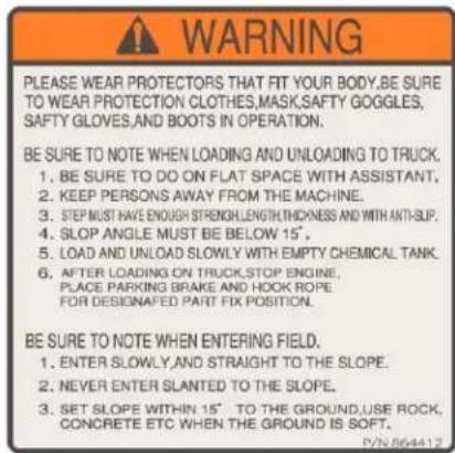
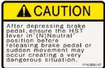
* Warning labels are attached on this machine. Carefully read these labels and understand the contents before commencing work. Peruse the following information provided on the labels.
Warning
- Constantly remove soiling and mud over the labels so that the information provided on them remains clearly visible.
- Replace damaged warning labels with new ones.
- If a part on which a warning label is attached has been replaced, be sure to attach a new label on the new part at the same location.
![[1] [2] [3] [4] [5] [6] [7] [8] [9]](/content/2026/05/941812/images/e0380b7322182d1be905a1241b14652d24b92e4338eab4c78cba3df0016a39d5.jpg)
[1] Part No. 689958
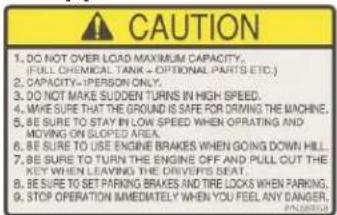
[4] Part No. 689960
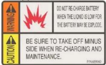
[2] Part No. 689962
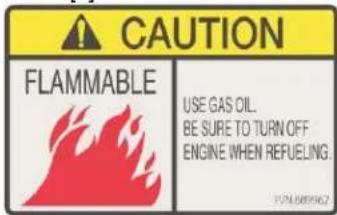
[5] Part No. 689961
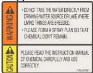
[3] Part No. 689963
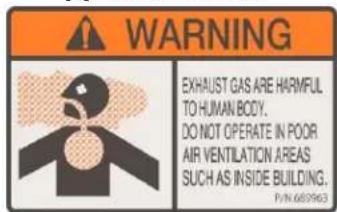
[6] Part No. 864418
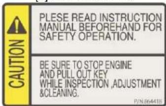
[7] Part No. 868146

[8] Part No. 689964
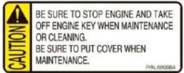
[9] Part No. 868145
[10]
natural_image
Technical line drawing of a mechanical assembly with no visible text or symbols[11]
natural_image
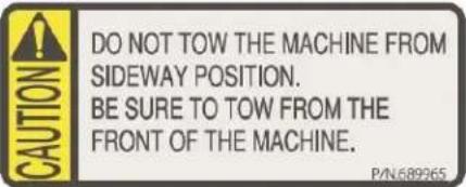
Technical line drawing of a mechanical assembly with no visible text or symbols[10] Part No. 689965
[11] Part No. 866073
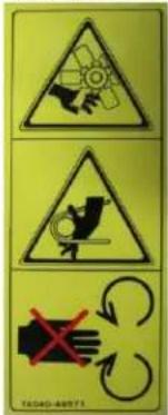
[14] (Manual Boom Open/Close Specification)
![[12] [13]](/content/2026/05/941812/images/06305f7bc34bb3a0d83d6b8e5f1b84c0e09d6df4718b766bb984341a5b3503f8.jpg)
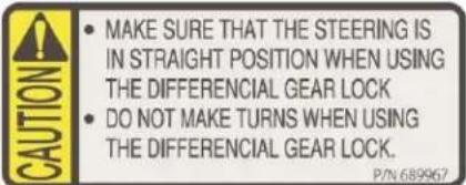
[12] Part No. 689967
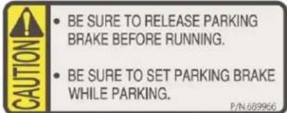
[13] Part No. 689966
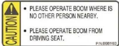
[14] Part No. 868163
![[17] [15] [16] [18] [14] (Specification J)](/content/2026/05/941812/images/32670c330436464ff05c0c55ef370c23c7a7916d5f838d5fa248cc0328763f28.jpg)
[15] Part No. 864412
[16] Part No.868147
[17] Part No.689969
[18] Part No.869750

[19] (Manual Boom Open/Close Specification)
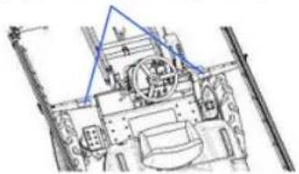
natural_image
Technical line drawing of a mechanical assembly with no visible text or symbols[20] Specifications J/Q only
natural_image
Technical line drawing of a mechanical assembly with no visible text or symbols[19] (Hydraulic Boom Open/Close Specification)
natural_image
Technical line drawing of a mechanical assembly with no visible text or symbols[20] Part No.880324
CAUTION
will be in lock position
it fully extended.
[19] Part No.868148

No step!
High risk of
falling or other
injury/damage may occur.
5 Name and Function of Each Device
■ Relating to Engine Operation
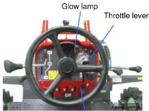
Key switch
(1) Key Switch
"OFF" --- The engine is stopped. Current does not flow. The ignition key is inserted and removed in this position.
"ON" --- The engine is turning. Current flows to each electrical component.
"GL" --- The glow lamp turns on. When the hand is released in this position, the switch will automatically return to the "ON" position.
“ST” --- The cell motor turns to start the engine. When the engine has started, immediately release the hand. When the hand is released, the switch will automatically return to the “ON” position.
- Because of the starting safety device, the engine will not start unless the auxiliary shift lever is put in the "N – Start" position.
(2) Throttle Lever
Pull the throttle lever toward you to turn the engine at high speed, or tilt it forward for low speed operation. When traveling on the machine, use the accelerator pedal to adjust the engine speed.
■ Traveling Operation
natural_image
Close-up of a red HST lever with visible control panel and mechanical components (no text or symbols)Auxiliary shift lever
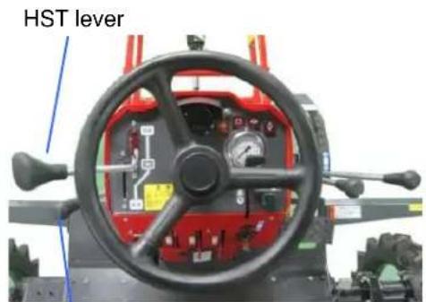
(1) HST Lever
Tilt the lever forward from the "N" position to move forward, or tilt it rearward to move in reverse. The more you tilt the lever, the higher the machine speed becomes.
(2) Auxiliary Shift Lever
There are two shift gears: one for traveling (high speed) and the other for spraying (low speed). To start the engine, put the auxiliary shift lever in the "N - Start" position.
Caution
- To perform auxiliary shift operation, put the HST lever in the "N" position and be sure to stop the machine. If the auxiliary shift lever is operated before the machine stops completely, the auxiliary transmission may be damaged.
(3) Differential Lock Pedal
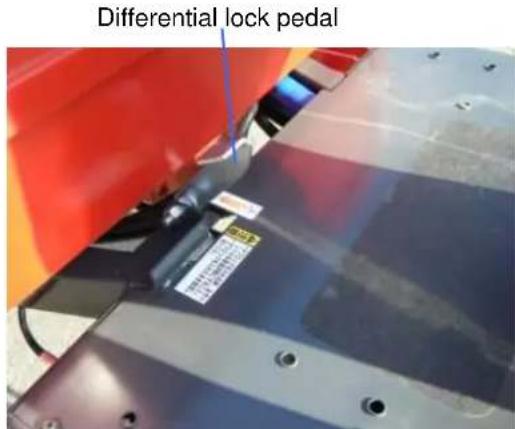
The differential lock device allows the front and rear tires on the left and right to be driven at the same speed. This is useful in preventing slips. The differential lock is actuated when the differential lock pedal is depressed, and cancelled when the pedal is released. Use this function in the following situations:
[1] The wheels on one side slip when going up/down an agricultural road or going over a furrow and the machine cannot move straight.
[2] The machine gets into an area of soft ground in the field and encounters difficulty traveling due to slipping wheels.

Caution
- Before actuating the differential lock, be sure to adjust the steering wheel to the straight-moving position. Also remember not to turn while the differential lock is actuated. The machine may not turn in the intended direction.
Caution
- Be sure to cancel the differential lock before turning. If the machine is turned forcibly with the differential lock on, the drivetrain may be damaged.
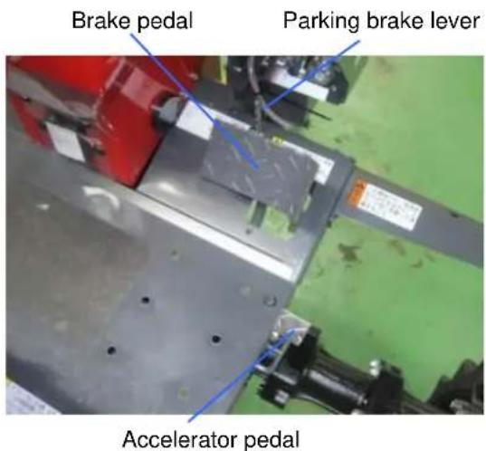
(4) Brake Pedal
Stepping on this brake applies brake to the machine.
(5) Parking Brake
Depress the brake pedal fully and hook the parking brake lever to the brake pedal. To release the brake, depress the brake pedal fully once again.

Caution
● Before leaving the machine, stop the engine and be sure to apply the parking brake, remove the ignition key, and chock the tires.
(6) Accelerator Pedal
While traveling, use the accelerator pedal to adjust the engine speed. Step on the accelerator pedal to raise the engine speed, or release it to run the engine idle.
(7) Power Steering Wheel
This hydraulic steering wheel is used to turn the machine or change its course.
Caution
- Avoid static steering (turning the steering wheel when the machine is not traveling), because it will cause the tires, rims, etc., to wear quickly.
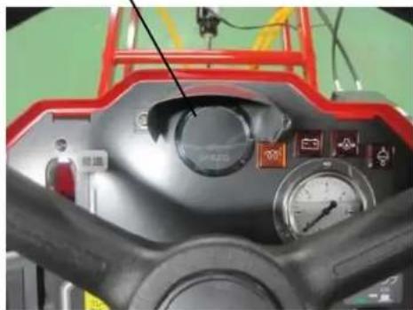
(8) Speedometer
Speedometer
natural_image
Close-up of a mechanical control panel with gauges and a red safety guard (no visible text or symbols)The traveling speed (km/h) is indicated.
* The indicated speed assumes a tire slip factor of 5%.
* If the tires are slipping in a field, etc., the actual traveling speed may differ from what is indicated by the speedometer.
(9) Seat
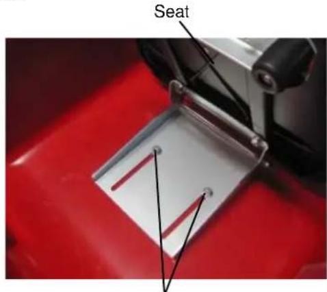
Hexagonal bolts
You can loosen the hexagonal bolts to slide the seat forward and backward. Once the seat position has been adjusted, securely tighten the hexagonal bolts.
(10) Warning Lamp
● Charge lamp (charge warning lamp)
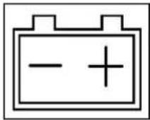
This lamp turns on to warn when a charge system error is detected while the engine is turning.
Caution
- If this lamp turns on, stop the engine and inspect the fan belt. If the belt is normal, have the machine inspected by the Maruyama dealer near you.
● Oil pressure lamp (oil pressure warning lamp)
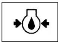
This lamp turns on to warn when the pressure of oil lubricating the engine interior drops while the engine is turning.
Caution
- If this lamp turns on while the engine is turning, immediately stop the machine in a safe place and stop the engine, and contact the Maruyama dealer near you.
● Continuing to travel on the machine despite the lamp remaining on may damage the engine. - The oil pressure warning lamp does not indicate insufficiency of oil. Check the oil amount using the oil level gauge. Checking/adding engine oil: P. 40
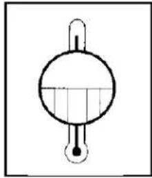
● Water temperature warning lamp
natural_image
Simple line drawing of a round-bottom flask with a side port and a handle (no text or symbols)This lamp turns on to warn when the engine is overheated.
Caution
● Never remove the radiator cap immediately after the engine has stopped or while the engine is turning, because it will cause burns. Wait for the water temperature to drop, and then put a piece of cloth, etc., over the radiator cap and remove the cap slowly.
Caution
- If this lamp turns on, move the machine to a well-ventilated place and keep the engine idle. When the water temperature warning lamp turns off, stop the engine and check if the engine oil or cooling water level is low, check the fan belt tension, and also check the radiator core and air cleaner for clogging. If the lamp turns on frequently, have the machine inspected by the Maruyama dealer near you.
(11) Monitor Lamp
(operation status check indicator lamp)
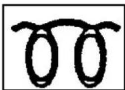
● Glow lamp (preheating indication)
natural_image
Simple line drawing of two interlocking ovals (no text or symbols)This lamp turns on if the key switch is in the "GL" position when starting the engine. It turns off once preheating is complete.
■ Relating to Pest Control [Common to All Specifications]
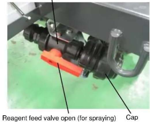
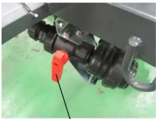
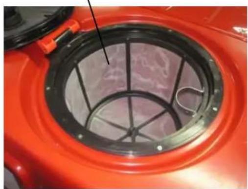
(1) Water Absorption Strainer/Water Filter Net Water absorption strainer
natural_image
Close-up of a mechanical assembly with black components and a red tool, no visible text or symbolsReagent feed valve closed
Water filter net
natural_image
Close-up of a red industrial machine casing with a circular vent and metal mesh structure (no visible text or symbols)Caution
- The water strainer/water filter net filters dust, etc., so be sure to clean the strainer/net after work.
[1] Keep the two-way cock in the "Spray" position during spraying or while the jet pump (optional) is used.
[2] When cleaning the water absorption strainer, keep the two-way cock in the "Stop" position if the reagent tank contain reagent.
[3] To discharge the remaining liquid from the reagent tank, put the two-way cock in the "Stop" position to remove the cap, and then put it in the "Spray" position to discharge the remaining liquid.
■ Relating to Pest Control [Manual Pressure Adjustment Specification]
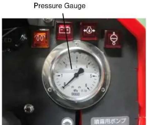
(1) Pressure Adjustment Dial Adjust the discharge pressure of the spray pump. While monitoring the pressure gauge, turn the pressure adjustment dial to a desired pressure.
![Maruyama BSA-500 - ■ Relating to Pest Control [Manual Pressure Adjustment Specification] - 1](/content/2026/05/941812/images/97f4cd9dd4aee812de459996690acdc14069d7b7b1091ab92cf61bca6039a548.jpg)
natural_image
Close-up of a red industrial machine with visible control knobs and mechanical components (no text or symbols)Pressure adjustment dial
(2) Pressure Gauge The pressure adjusted with the pressure adjustment dial is indicated.
Spray pump switch
![Maruyama BSA-500 - ■ Relating to Pest Control [Manual Pressure Adjustment Specification] - 3](/content/2026/05/941812/images/181614e72d1db03841328e02d985af0e344c4ce28c242f2fcda9f1ff678c46d6.jpg)
natural_image
Close-up of a red industrial machine component with control knobs and a green indicator light (no visible text or symbols)Spray cocks
(3) Spray Cocks Raising the lever causes reagent to be sprayed from the boom nozzle. A desired spray location can be selected from among the left, center and right bottom nozzles.
(4) Spray Pump Switch Pressing the pump button turns the spray pump.
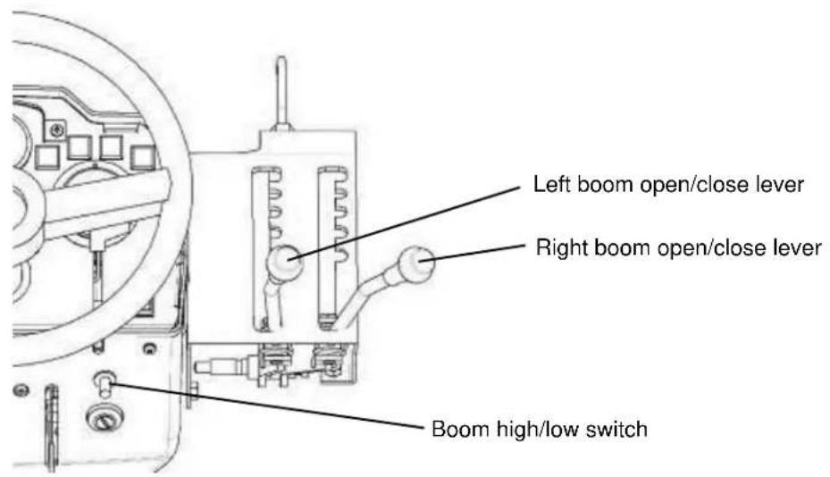
■ Operating the Boom [Manual Open/Close & Electrical High/Low Specification]
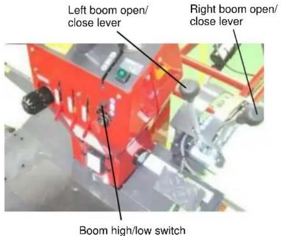
(1) Boom High/Low Switch
Turn this switch up/down to adjust the height of the entire boom.
(2) Left Boom Open/Close Lever
Tilt the lever to the left and remove it from the cutout groove and then press it forward to open the left boom. Pull the lever backward to close the left boom. After the operation, make sure the lever is securely engaged in the cutout groove.
(3) Right Boom Open/Close Lever
Tilt the lever to the left and remove it from the cutout groove and then press it forward to open the right boom. Pull the lever backward to close the right boom. After the operation, make sure the lever is securely engaged in the cutout groove.
- Sit in the driver seat and if operating the lever of each boom is difficult, stop the machine temporarily and apply the parking brake, and then stand on the driver seat and operate the lever. - The switch can be operated with a small force. Do not apply an excessive force on the switch.
(4) Boom Receiver
Keep the left and right booms on the boom receivers while traveling or during transport.
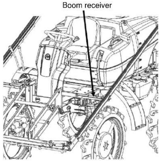
Caution
- Do not operate the booms while the booms are secured on the boom receivers with ropes, etc., because doing so may damage the booms.
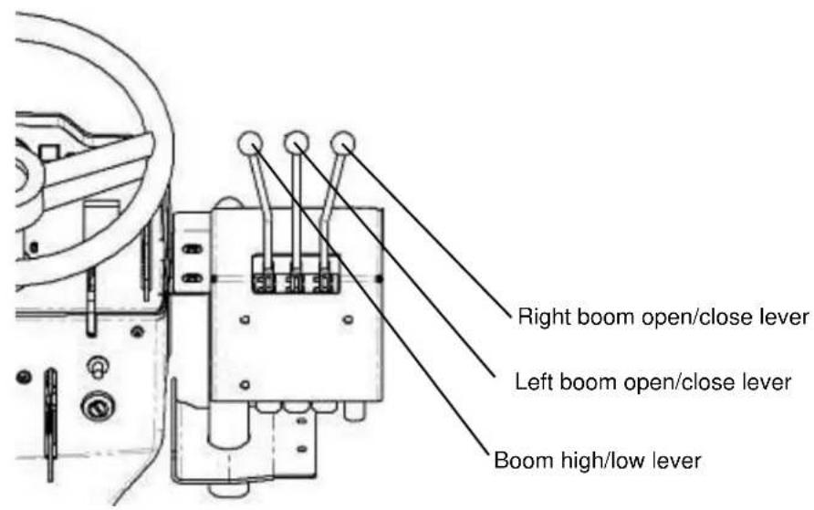
■ Operating the Boom [Specification J (Hydraulic Open/Close & High/Low Specification)]
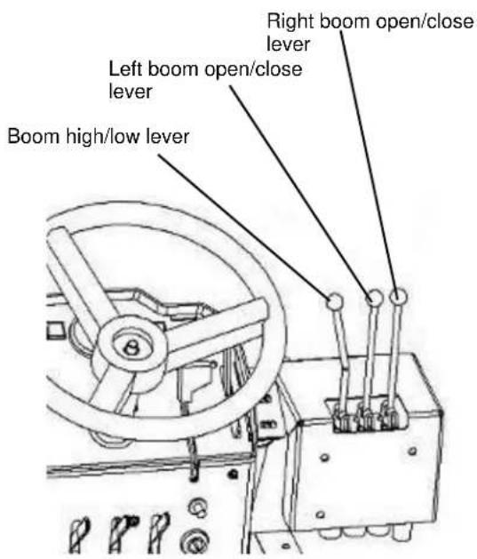
(1) Boom High/Low Lever
Pull the lever toward you to raise the entire boom, or tilt it forward to lower the entire boom.
(2) Left Boom Open/Close Lever
Tilt the lever forward to open the left boom, or pull it toward you to close the left boom.
(3) Right Boom Open/Close Lever
Tilt the lever forward to open the right boom, or pull it toward you to close the left boom.
● The lever actuates with a small operating force. Do not apply any unnecessary force.
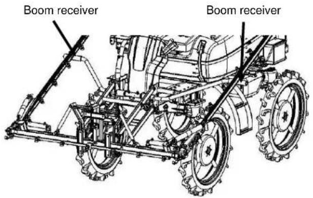
(4) Boom Receiver
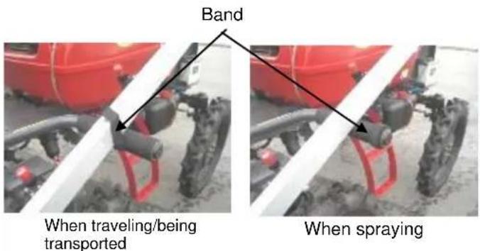
Store the left and right booms in their boom receivers while the machine is traveling or being transported, and fix the boom and boom receiver using the band. When spraying, remove the band and wrap it around the boom receiver so that it won't be lost.
■ Other
(1) How to Install/Remove the Rear Cover
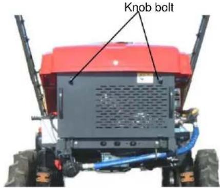
[1] To remove the rear cover on the back, loosen the two knob bolts, hold the handle and pull the cover upward to remove.
[2] To install the rear cover on the back, guide its top face through the hood and hook the bottom face, and then securely tighten the knob bolts.
Caution
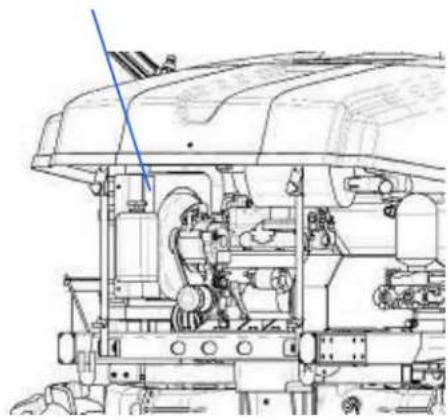
● Never open the rear covers while the engine is running. The rotating parts may be exposed and cause injuries.
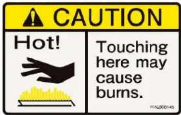
- Do not touch the muffler while hot. Burns may result.
- Once the rear covers have been installed, be sure to securely tighten the knob bolts. If the bolts are loose, they may drop out during transport and cause accidents.
(2) Tires
The wheelbase can be adjusted by reversing the tires or adding a spacer or spacers (optional).
Caution
- Do not use spacers other than those provided as an option.
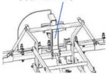
(3) Towing Hooks
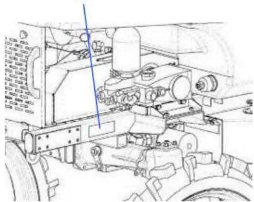
[Front Side of Frame]
natural_image
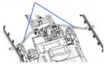
Close-up of a mechanical assembly with a blue arrow pointing to a component (no visible text or symbols)[Back Side of Frame]
natural_image
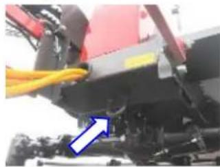
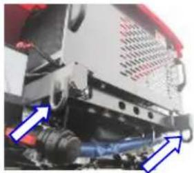
Close-up of a mechanical assembly with blue arrows pointing to components (no visible text or symbols)If the machine gets stuck in a field and must be pulled out, use these hooks to pull the machine forward and backward. Keep the booms at the top positions.
Warning
- Do not use the towing hooks to tow other machine, etc. The machine may tip over.
Caution
● Never pull the towing hooks sideways. The hooks will come off easily and the machine will tip over.
Caution
- Never pass a rope, etc., over the boom unit and pull the rope. The machine will be damaged.
6 How to Travel/Transport
■ How to Start/Stop the Engine
(1) How to Start

Warning
- To ensure safety, apply the parking brake, put the auxiliary shift lever in the "N – Start" position and put the HST lever in the "N" position before starting the engine.
- Provide sufficient ventilation when starting the engine indoors. Failure to do so may cause exhaust gas poisoning.

Caution
- Before starting the engine, check the surrounding areas to ensure safety and also confirm that the cover is closed.
Caution
- Once the engine is started, do not apply load but simply warm up the engine for approx. 5 minutes so as to spread oil to each metal area fully. Take note that, if load is applied immediately after the engine is started, breakdown may occur due to seizure, damage, etc.
Start the engine from the driver seat after giving a cue to people around the machine and also checking the surroundings to ensure safety.
[1] Apply the parking brake.
[2] Put the HST lever in the "N" position and auxiliary shift lever in the "N - Start" position.
[3] Insert the ignition key in the key switch.
[4] Tilt the throttle lever forward for "low speed" operation.
[5] Turn the key switch to the "GL" position and keep it in this position until the glow lamp turns off.
[6] Turn the key switch key to the "ST" position. Once the engine has started, release the switch. The key switch will automatically return to the "ON" position.
[7] Check each warning lamp to confirm that the engine is normal. If any warning lamp is on, immediately stop the engine and take an appropriate measure. If you hear abnormal noise different from what you hear every day, stop the engine and investigate the cause. If the cause cannot be identified, contact your Maruyama dealer.
[8] Warm up the engine for 5 minutes before commencing work.

Warning
● Warm up the engine outdoors to prevent exhaust gas poisoning.

Caution
- Be sure to apply the parking brake and keep your eyes on the machine while the engine is warming up.
- If the engine does not start with the first try on a cold day, etc., repeat preheating and try starting the engine. Do not turn the cell motor for more than 10 to 15 seconds. Before restarting the engine, wait for 30 seconds to restore the battery voltage.
- Do not turn the key switch to the "ST" position while the engine is turning.
- The engine is still cold immediately after the start, so do not rev up the engine or raise the engine speed unnecessarily. It may cause breakdown.
- Check the exhaust condition for abnormality and if any abnormality is found, immediately stop the engine and change fuel or oil, or contact your Maruyama dealer.
(2) How to Stop
[1] Push the throttle lever forward to lower the engine speed.
[2] Let the engine operate at the low speed for approx. 5 minutes to cool down.
[3] Turn the key switch to the "OFF" position.
(3) Break-In Operation
Caution
- How the machine is handled when new (during initial 50 hours) affects the life and performance of the machine. In particular, pay attention to the items specified below during this period.
[1] Fully warm up the engine before commencing work.
[2] Change oils according the Oil Change Table after initial 50 hours of operation. (Refer to P. 38)
■ How to Travel
Warning
- This machine cannot travel on local road and must be carried on a truck, etc., to a field.
Caution
- When taking off, check the surroundings to ensure safety.
- Before leaving the machine, be sure to apply the parking brake, stop the engine and remove the ignition key. Otherwise, an unexpected person may touch the machine when no one is around and cause an accident.
(1) Taking Off
[1] Put the HST lever in the "N" position and auxiliary shift lever in the required position.
[2] Release the parking brake.
[3] Gradually tilt the HST lever in the required position to take off.
Caution
- When taking off, thorough check not only the rear, but also the left and right and be careful not to let the booms contact people or obstacles.
- Operate the HST lever slowly. Quick operation may cause the machine to take off or stop suddenly, creating a dangerous situation.
● While traveling, do not keep your foot on the brake pedal.
(2) Travel
Caution
- Do not carry anyone other than the driver, or objects.
● Wear a helmet to ensure safety. - Exercise due caution and lower the speed when going through a narrow agricultural land or on a road with shoulders, Trim weeds to expose the road shoulders.
- Adjust the traveling speed using the HST lever, throttle lever and accelerator pedal.
- Drive according to the traffic rules even on private roads or on agricultural land.
Caution
- When traveling, be sure to store the booms on the boom receivers. If the booms are floating on the boom receivers, the booms will be damaged as a result of traveling.
(3) How to Stop
[1] Slowly return the HST lever to the "N" position to stop the machine.
[2] Tilt the throttle lever forward to lower the engine speed.
Caution
- After you have stepped on the brake pedal and the machine has stopped, be sure to put the HST lever in the "N" position; otherwise, the machine may take off suddenly and create a dangerous situation.
- Before leaving the machine, remove the ignition key to ensure safety.
(4) Auxiliary Shift Operation
[1] Stop the machine fully.
[2] Shift the auxiliary shift lever to the required position.
Caution
- Do not perform shift operation while traveling. It may cause breakdown.
(5) How to Park
[1] Apply the parking brake.
[2] Stop the engine.
[3] Chock the wheels.
Caution
- When parking, stop the engine, apply both the parking brake and chocks, and be sure to remove the ignition key.
Caution
● The booms may drop due to their dead weights, so do not put objects underneath the booms.
(6) How to Get In/Out
[1] Get in/out of the machine using the grip and steps.
[2] When getting out of the machine, operate the boom high/low switch (or the lever in the case of the specification J) to move each boom to the highest possible position and get off facing backward (in the same posture in which you got in the machine).
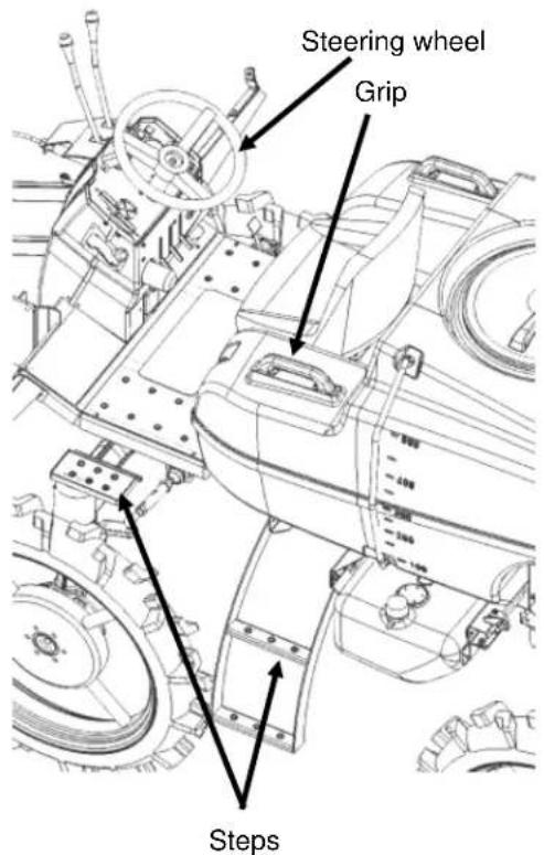
Caution
- Do not grab the steering wheel. The machine may tip over.
- Be sure to get off the machine facing backward. If you get off the machine facing forward, the machine may tip over.
■ How to Load/Unload to/from a Truck
Loading/unloading the machine to/from a truck involves great danger. Observe the following instructions and exercise due caution to safety when loading/unloading the machine to/from a truck.

Warning
- Load/unload the machine on flat ground in the presence of/with guidance from the assistant. Also, keep people away from the machine.
● The guiding person must not stand immediately in front of or at the back of the machine. - Load/unload the machine when the reagent tank is empty.
- Use anti-slip, hook-type footboards of sufficient strength, length and width.
- Securely hook the footboards by leaving no height gap or misalignment on the load-carrying platform.
| Length | At least four times the load-carrying platform of the machine |
| Width | 30 cm or more |
| Quantity | 2 pcs |
| Strength | Each board should be able to withstand at least 750 kg of mass. |
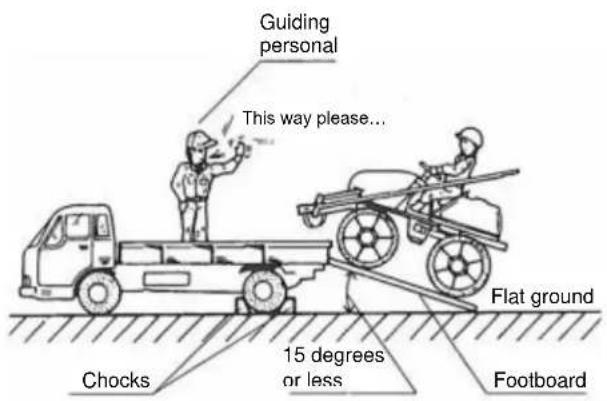
[1] Use a truck whose maximum payload is 2,000 kg or more.
[2] Put the shift lever on the truck in the "1st" or "R" position, pull the parking brake, and apply chocks.
[3] Empty the reagent tank and drive forward to load the machine. Move at a very low speed by tilting the HST lever forward slightly, with the auxiliary shift lever in the spray position. When unloading, drive in reverse in the same manner.
[4] If the engine of the machine stalls during loading or unloading, immediately step on the brake pedal and then gradually release the brake to lower the machine onto the road.
[5] Once the machine has been loaded onto the truck, apply the parking brake.
[6] During transport, secure the booms to the boom receivers with ropes, etc., to prevent the booms from opening.
[7] Pass ropes at the front and rear towing hooks to secure the machine.
[8] Be sure to close the gate of the truck.
Caution
- If ropes are passed at positions other than the towing hooks, the machine may be damaged.
- When securing the machine to the truck, do not tighten the wire ropes with an excessive load exceeding 4900 N (500 kg).
- Do not operate the booms while they are secured to the boom receivers with ropes, etc., because the booms may be damaged.
7 Pest Control Work
■ How to Enter/Exit a Field
Pay due attention when entering a field from road.
Warning
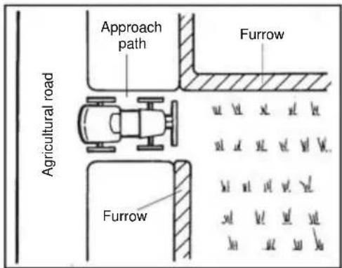
- Enter/exit a field at a very slow speed by tilting the HST lever forward slightly, with the auxiliary shift lever in the spray position. When entering, also orient the machine perpendicular to the furrows. If the machine is diagonal, it may tilt sideways and tip over, causing an accident.
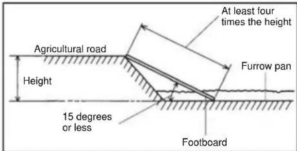
- Maintain the approach path so that the inclination angle of approach to the field is kept within 15 degrees.
- If the approach path to the field is soft, or the inclination angle is 15 degrees or more, be sure to use footboards to keep the inclination angle within 15 degrees.
* If the length of the approach path is at least four times the height of the road from the field, the inclination angle is within 15 degrees. - When going over a furrow, be sure to approach by orienting the machine perpendicular to the furrow and use footboards whenever possible. Move slowly with the auxiliary shift lever in the spray position.
■ How to Feed Water
Caution
- When feeding water, be sure to apply the parking brake, latch the tires, and put the HST lever in the "N" position.
(1) Adding the Required Amount of Water in the Reagent Tank
* If no water supply facility is available, a jet pump (optional (sold separately)) would be useful.
(2) How to Operate the Jet Pump
[1] Prime around 20 L of water into the reagent tank. [2] Connect the pipe from the jet pump to the cock connected to the spray pump, and open the cock
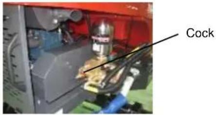
[3] Throw the strainer end of the jet pump into the water source and insert the opposite end to the water inlet of the reagent tank.
[4] Close the spray cock fully.
[5] Put the throttle lever to the idling position and press the spray pump switch.
[6] Pull the throttle lever and adjust the engine speed to a medium level.
[7] Operate the pressure adjustment dialto adjust the spray pressure to between 2 and 2.5 MPa.
[8] When the required amount for spraying is reached, close the cock of the jet pump.
[9] Return the throttle lever to the idling position and press the spray pump switch to stop the spray pump, and then remove the jet pump.
Warning
● Never feed water directly from a drinking water source or any lake or pond used for aquatic farming.
■ Reagent Preparation and Handling
(1) Reagent Preparation
[1] Before preparing the reagent, check the spray condition with water.
(Refer to P. 30)
[2] Prepare only the required amount using a dedicated container.
[3] Dissolve the water-dispersible powder well with a small amount of water and then add the diluted powder.
[4] Confirm that the spray cock is in the "Closed" position and liquid feed valve is "Open," and then press the spray pump switch. The spray pump will actuate and agitation will start in the reagent tank at the same time.
[5] Put the reagent in the reagent tank by making sure it does not spill out of the tank, and agitate the reagent fully.
Caution
● The spray pump and jet agitation are interlocked. Once the spray pump stops, jet agitation also stops. Do not stop the spray pump while reagent remains in the tank, because chemical damage may occur.
Caution
- Carefully read the operation manual of the applicable reagent and use the reagent correctly.
- Be sure to use the water filter net and when the spraying is over, clean the net together with the water absorption strainer.
■ Spray Inspection
(1) Opening the Spray Cock and Checking the Spray Condition
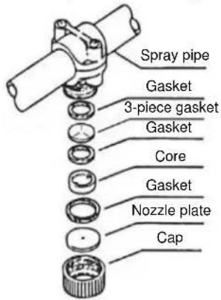
[1] Inspect the nozzle for clogging due to dust, etc.
[2] Check each spray cock (left nozzle, center nozzle and right nozzle).
- Long hours of use causes the nozzle plate to wear and discharge flow rate to increase. When this happens, replace the nozzle plate.
[Other Than Specifications J]
[Specifications J]
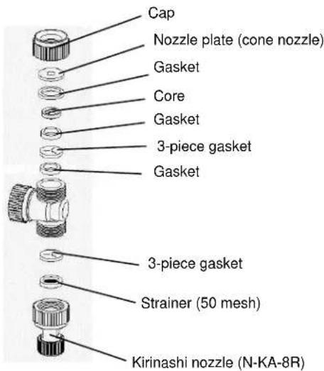
● Types and quantities of standard factory-set nozzles [Other Than Specifications J]
| Left boom | Cone nozzle (∅1.6) | 10 pcs |
| Center boom | 6 pcs | |
| Right boom | 10 pcs | |
| Total | 26 pcs | |
● Types and quantities of standard factory-set nozzles [Specifications J]
| Left boom | Cone nozzle (∅1.4) | Uncut nozzle (N-KA-8R) | For rice shower nozzle (25)* | 13 pcs |
| Center boom | 7 pcs | |||
| Right boom | 13 pcs | |||
| Total | 33 pcs | |||
* Optional (sold separately).
● Table of nozzle discharge flow rates (per nozzle) (L/min)
Cone nozzle
| 1.0MPa | 1.5MPa | 2.0MPa | |
| ∅1.0 | 0.53 | 0.66 | 0.77 |
| ∅1.1 | 0.60 | 0.73 | 0.85 |
| ∅1.2 | 0.66 | 0.82 | 0.96 |
| ∅1.3 | 0.73 | 0.89 | 1.05 |
| ∅1.4 | 0.78 | 0.98 | 1.12 |
| ∅1.5 | 0.86 | 1.09 | 1.28 |
| ∅1.6 | 0.96 | 1.20 | 1.39 |
Caution
- Be sure to use water when inspecting the spray condition.
Caution
- Do not switch the 2-way or 3-way switching nozzle during spraying. The switching nozzle may be damaged.
- Turn the 2-way or 3-way switching nozzle clockwise to switch the nozzle.
■ Spray Plan

Warning
- Make the spray planning so that there won't be any chemical left.
(1) Spray Planning
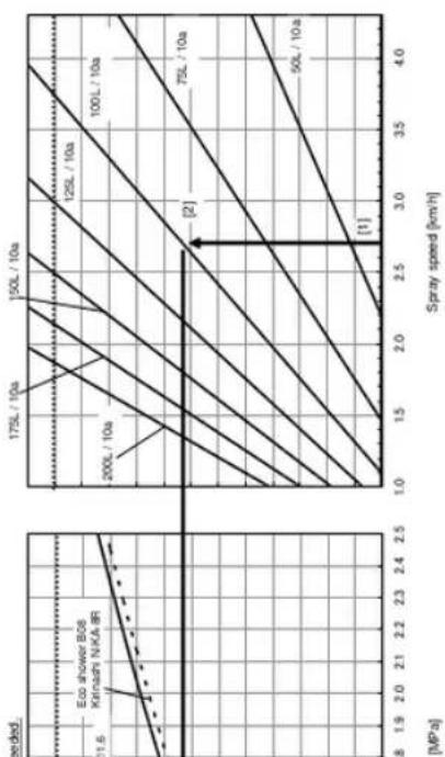
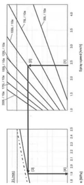
In spray planning, determine the spray amount per unit area (spray amount per 10 a) first, and then select the spray speed and obtain the nozzle pressure. The nozzle pressure can be obtained using quick calculation diagrams.
(2) How to Use the Quick Calculation Diagrams
You can use the quick calculation diagrams to obtain the nozzle pressure with ease.
"Example"
[Other Than Specifications J]
[1] Spray speed: 2.7 km/h
[2] Spray amount: 100 L per 10 a
[3] Use a standard cone (ceramic) ∅1.6 nozzle.
[4] From the quick calculation diagrams, the nozzle pressure is obtained as 1.6 (MPa).
[Specifications J]
[1] Spray speed: 2.4 km/h
[2] Spray amount: 100 L per 10 a
[3] Use a standard cone (ceramic) ∅1.4 nozzle.
[4] From the quick calculation diagrams, the nozzle pressure is obtained as 1.9 (MPa).
[Supplement]
The quick calculation diagrams assume a tire slip factor of 10% for the boom sprayer by considering the losses through the nozzles, etc.
The tire slip factor of the boom sprayer may vary depending on the conditions of the field, in which case the diagrams must be corrected for the difference in slip factor.
Depending on the state of the field, the tire slip factor may vary and the spray speed may deviate, in which case the nozzle spray amount must be set according to these different slip factor/spray speed.
For more accurate spraying measure the actual slip factor in the field.
● Rough guide for slip factor
5% --- General crop field where the depth to the furrow pan is approx. 10 cm
10% --- Field where the depth to the furrow pan is approx. 15 to 20 cm (where a ride-on rice planting machine can be used without problems)
15% --- Field where the depth to the furrow pan is approx. 20 to 25 cm
* Take note that the machine may not be able to travel in a field where the depth to the furrow pan is 25 cm or more. Also remember that the machine can travel more smoothly when the field is filled with water.
Caution
- When spraying in a field of a higher slip factor (greater depth to the furrow pan), reduce the amount of water added to the tank.
- Adjust the nozzle pressure within a range of 1.0 to 2.5 MPa.
[Other Than Specifications J]
line
| Spray speed (km/h) | Speed needed (MPa) | Volume (L) / 10a | | ------------------ | ------------------ | ---------------- | | 1.0 | 11.6 | 50L / 10a | | 1.5 | 17.5 | 7.5L / 10a | | 2.0 | 150L / 10a | 100L / 10a | | 2.5 | 125L / 10a | 125L / 10a | | 3.0 | 100L / 10a | 150L / 10a | | 3.5 | 75L / 10a | 175L / 10a | | 4.0 | 50L / 10a | 200L / 10a |[Specification J]
line
| Spray speed [km/h] | Dimensional Value | | ------------------ | ----------------- | | 1.8 | 3 L/min | | 1.9 | 3 L/min | | 2.0 | 3 L/min | | 2.1 | 3 L/min | | 2.2 | 3 L/min | | 2.3 | 3 L/min | | 2.4 | 3 L/min | | 2.5 | 3 L/min | | 1.0 | 200L / 10a | | 1.5 | 175L / 10a | | 2.0 | 150L / 10a | | 2.5 | 125L / 10a | | 3.0 | 100L / 10a | | 3.5 | 75L / 10a | | 4.0 | 50L / 10a |■ Spray Method

Warning
- Wear clothes that properly fit your body. Prepare protective clothes, pest control mask, protective glasses, rubber gloves, work shoes, etc., and dress safely during work.
[1] Spray safely using a method appropriate for the terrain and field condition.
[2] The person performing spraying should wear protective gears for agrichemical spraying (such as a pest control mask, protective glasses, boots, rubber gloves, work uniform and helmet) to prevent the reagent from coming in direct contact with the body.
[3] Whenever possible, spray early in the morning or in the event when there is no wind.
[4] Do not enter the areas where agrichemical has already been sprayed.
[5] Keep only the required amount of spray agent in the reagent tank to prevent leftovers.
[6] Check the applicable spray amount, spray pressure and traveling speed beforehand.
[7] Remove obstacles from the traveling path beforehand and make preparations to ensure safe traveling, and provide wide enough turning areas so that the machine can turn without problems.
■ Spraying
[1] Press the spray pump switch to operate the spray pump.
[2] Pull the throttle lever fully to set the engine to a normal speed.
[3] Check if the reagent has been agitated fully.
[4] Use the pressure adjustment dial to adjust the pressure. Since the pressure when the spray cock fully closed is different from the pressure during spraying, adjust the pressure once again to a desired level during spraying.
[5] Open the booms.
1) Operate the boom high/low switch (or lever in the case of the specification J) to move the booms to positions higher than the boom receivers.
2) Operate the left and right boom open/close levers to open the booms.
[6] Put the auxiliary shift lever in the spray position.
[7] Open the spray cock and slowly tilt the HST lever in the moving direction until a desired speed is achieved. Thereafter, open/close the spray cock to switch between spraying and stopped modes.
[8] When spraying is finished, lower the engine speed and press the spray pump switch to stop the spray pump.
Caution
- Do not close the left and right booms at low positions. The booms may contact the tires, boom receivers, etc., and get damaged.
- When opening the left and right booms, operate the boom high/low lever to raise the booms to sufficient heights beforehand. If the booms are low, the tips of the booms may contact the ground when the booms are opened.
■ After Spraying
[1] Open the reagent tank lid and remove the water filter net, and wash the net together with the water absorption strainer.
[2] Install the water absorption strainer/water filter net once again, add around 100 L of freshwater in the reagent tank, close the reagent tank lid, and operate the spray pump.
[3] Spray freshwater from the nozzle to perform cleaning of pipe interior.
[4] When the reagent tank becomes empty, run the spray pump idle for approx. 30 seconds with the engine running at low speed, to drain water from the tank.

Caution
- Do not perform cleaning while the tank lid is open. Agitated liquid may splash and scatter.
8 Maintenance
■ Maintenance and Inspection (Inspection and Servicing Methods)
So that this machine can be used safely, perform the necessary periodic servicing based on the methods explained here.
The inspection and servicing methods are divided into “Startup inspection” and “Period inspection.” Applicable methods are explained under each grouping.

Caution
- Before performing inspection and servicing, be sure to stop the engine, apply the parking brake, remove the ignition key, and disconnect the negative terminal end of the battery cable from the battery.
- If any inspection or servicing item requires the engine to remain running, do not perform such item on your own, but always contact the service personnel at your Maruyama dealer instead.
- Dispose of the battery, oils, coolant, etc., properly after consulting your Maruyama dealer, etc. Careless disposal of the battery, oils, coolant, etc., on land, into a river, etc., may be construed as a punishable violation of law.
| Periodic Inspection Standards1. The applicable inspection timing is indicated by O.2. The timing of initial inspection is indicated by *. | |||||||
| Inspection item | Inspection timing | Judgment criterion | |||||
| Start of work | Every 6 months | Every 12 months | Hours | ||||
| Steering operation | Steering wheel handle | Play, looseness, rattling | O | O | O | *50 | |
| Operating feel | O | O | O | *50 | |||
| Rods and arms | Looseness, rattling, damage | O | O | *50 | |||
| Knuckle | Rattling of joint | O | |||||
| Steering device | Wheel, alignment | O | Toe-in: 0 mm | ||||
| Steering wheel | Looseness, rattling, damage | O | O | *50 | |||
| Power steering | Clogging of oil filter | O | |||||
| Hose damage, amount of oil | O | O | O | ||||
| Brake | Brake pedal (also used as clutch) | Catching by parking brake lever | O | O | O | ||
| Brake effect | O | O | O | *50 | |||
| Activation of clutch | O | O | O | ||||
| Rods and cables | Looseness/rattling and damage | O | O | ||||
| Running gears | Wheel | Tire pressure | O | O | O | *50 | 240 kPa |
| Tire cracks and damage | O | O | O | ||||
| Abnormal wear of tire | O | O | O | ||||
| Metal pieces, stones and other foreign matters on tire | O | O | O | ||||
| Cracks, rattling | O | O | |||||
| Looseness of bolt | O | O | *50 | Wheel bolt tightening torque: 92 N·m | |||
| Rim damage | O | O | |||||
| Rattling of wheel bearing | O | ||||||
| Drivetrain | HST | Leakage of oil | ○ | ○ | ○ | ||
| Auxiliary transmission | Rattling of operating mechanism | ○ | ○ | ||||
| Leakage of oil | ○ | ○ | ○ | ||||
| Propeller shaft | Looseness of link | ○ | ○ | *50 | |||
| Rattling of spline | ○ | *50 | |||||
| Rattling of bearing | ○ | *50 | |||||
| Run-out of propeller shaft | ○ | *50 | |||||
| Differential | Leakage of oil | ○ | ○ | ○ | |||
| V-belt | Looseness and damage of belt | ○ | ○ | ○ | *50 | ||
| Hydraulics | Oil tank | Amount and leakage of oil | ○ | ○ | ○ | ||
| Oil cooler | Clogging of cooling fan | ○ | ○ | ○ | |||
| Leakage of oil | ○ | ○ | ○ | ||||
| Hydraulic valve Note 1 | Leakage of oil | ○ | ○ | ○ | |||
| Hydraulic cylinder Note 1 | Leakage of oil | ○ | ○ | ○ | |||
| Filter | Clogging | ○ | *50 | Replace every 200 hours | |||
| Piping | Looseness of joint and leakage of oil | ○ | ○ | ○ | |||
| Mechanical devices | Starting device | Degree of pinion meshing | ○ | ||||
| Charge device | Charge action | ○ | ○ | ||||
| Battery | Fluid level | ○ | ○ | *50 | Fully charged: 1.260 (20°C) Fully discharged: 1.060 (20°C) | ||
| Specific gravity of fluid | ○ | ||||||
| Electrical wirings | Loose and damaged connection parts | ○ | ○ | ||||
| Main body | Ease of starting and abnormality | ○ | ○ | ○ | |||
| Condition at low speed and during acceleration | ○ | ○ | |||||
| Exhaust condition | ○ | ○ | ○ | ||||
| Condition of air cleaner element | ○ | ○ | ○ | Replace every year. | |||
| Compressive pressure | ○ | ||||||
| Valve gap | ○ | 0.1 mm to 0.2 mm | |||||
| Lubrication device | Leakage of oil | ○ | ○ | ○ | |||
| Dirtiness and amount of oil | ○ | ○ | ○ | *35 | Replace every 100 hours. | ||
| Clogging of oil filter | ○ | *35 | Replace every 200 hours. | ||||
| Fuel device | Leakage of fuel | ○ | ○ | ||||
| Fuel strainer | ○ | ○ | *25 | Replace every 400 hours. | |||
| Fuel line cracks/damage | ○ | ○ | ○ | ||||
| Cooling device | Leakage of water | ○ | ○ | ○ | |||
| Amount of water | ○ | ○ | ○ | ||||
| Function of radiator cap | ○ | ○ | Open/close pressure: 90 kPa | ||||
| Looseness and damage of fan belt | ○ | ○ | ○ | 100 | Deflection when the center of the belt is pushed with a force of 100 N: 7 mm | ||
Note 1: [Specifications J only]
| Periodic Inspection Standards1. The applicable inspection timing is indicated by O.2. The timing of initial inspection is indicated by *. | |||||||
| Inspection item | Inspection timing | Judgment criterion | |||||
| Start of work | Every 6 months | Every 12 months | Hours | ||||
| Instruments | Operation | O | O | O | |||
| Soiling and damage | O | O | |||||
| Exhaust pipe and muffler | Looseness and damage of mount | O | O | ||||
| Muffler function | O | ||||||
| Machine frame and body | Looseness and damage | O | O | ||||
| Location where abnormality was found during operation the day before | Confirm that the applicable location is free from abnormality. | O | |||||
| Other | Lubrication condition at each part of chassis | O | O | ||||
| Other items | Fuel tank | O | O | ||||
| Water absorption strainer | O Note1 | Clean. | |||||
| Tank water filter net | O Note1 | Clean. | |||||
| Nozzle | O | O | Inspect for clogging and wear, and replace. | ||||
| Boom | O | O | Operating condition | ||||
| Each fastening part | O | O | Tighten securely. | ||||
Note 1. Clean after every operation.
■ Oil Change Table
| No. | Item | Applicable oil | Volume | Initial change (hours) | Periodic change and adding (after every specified hours) |
| 1 | Fuel | Diesel oil | 20 L | - | - |
| 2 | * Engine oil | SAE10W-30API CF grade or better | 2.5 L | 50 | 100 |
| 3 | Oil tank | Hydraulic oil (wear resistance) VG32 (ISO) | 13 L | 200 | |
| 4 | Auxiliary transmission oil | Gear oil SAE 90 | 2.0 L | 600 | |
| 5 | Front/rear differential oil | 1.0 L | |||
| 6 | Spray pump, crank case | SAE10W-30API SJ grade or better | 0.6 L | 100 | |
| 7 | Spray pump, cylinder base metal | 3 to 5 drips | - | Every 100 hours or every year | |
| 8 | Each wire | - | At start of work | ||
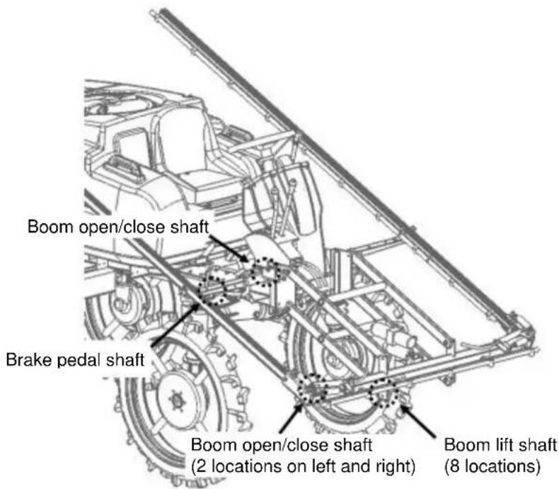
| 9 | Brake pedal shaft | Chassis grease | Appropriate amount | - | 20 |
| 10 | Boom lift & open/close shaft | ||||
| 11 | Radiator | LLC | 2.6 L | - | No more than 600 hours or 2 years |
* Oil filter cartridge included.
● Greasing locations [Other Than Specifications J]
● Greasing locations [Specifications J]
Brake pedal shaft
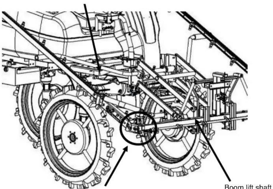
Boom rotational axis (3 locations each on left and right)
■ Inspection Procedures
(1) Engine Oil
[Check] With the machine horizontal, pull out the oil gauge, wipe the tip with a clean cloth and put back the gauge, and pull it out again to check the oil level. If oil is at the LOWER level or below, add oil to the specified level. (Check the oil level before the engine is started or at least 5 minute after the engine has stopped.)
[Change] Remove the drain plug, drain oil, and fill new engine oil.
[Engine oil] SAE10W-30 API CF grade for diesel engine
[Amount of oil (Oil filter cartridge included).] 2.5 L
[When to change] Initial change: 50 hours Periodic change: Every 100 hours
Used oil can be drained easily when the engine is hot. Oil gauge
natural_image
Close-up of automotive engine components including hoses and a blue vehicle (no visible text or symbols)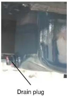
Caution
- When draining oil, exercise caution not to get burned. Do not touch any of the parts directly with your hand.
- Oil filter cartridge
Replace every 200 hours (or after 50 hours initially).
[1] The oil filter is of cartridge type, so remove the entire case with a filter wrench and replace it with a new one.
[2] After the new oil filter has been assembled, operate the engine to check for leakage of oil.
- After the oil change, stop the engine after (5 minutes of) idling, wait for 10 to 20 minutes and then check the oil level. If there is not enough oil, add oil.
(2) Air Cleaner
Caution
- Be sure to remove and clean the air cleaner element before operating the machine.
[3] To clean the element, spray air (0.21 MPa or less) onto the inner side of the element or shake the element gently to remove dust.
[4] Replace the element once a year.
[5] When installing the cup, be sure to assemble with the top side facing up.
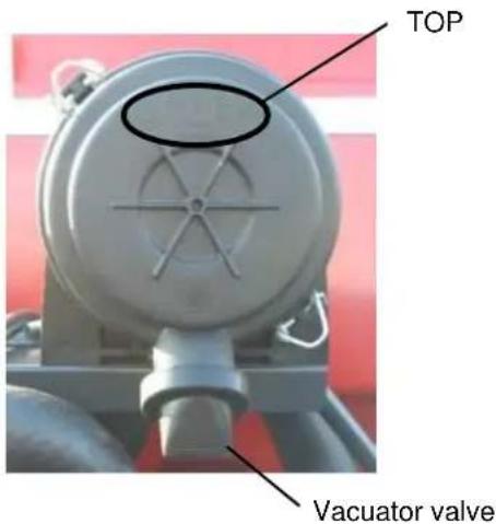
* Cleaning the Vacuator valve Open the Vacuator valve and remove large dust particles.
(3) Inspecting the Insect Net
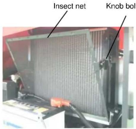
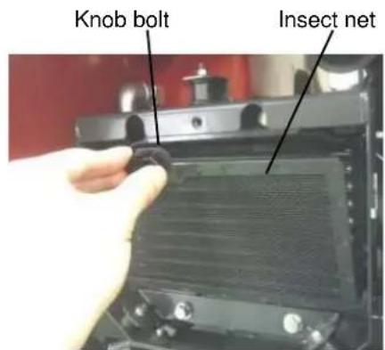
If the net is clogged, loosen the knob bolts to remove the insect net and remove insects and other contaminants attached on the surface.
(4) Inspecting the Fuel System
■ Fuel tank
Check if the tank contains enough diesel oil. If not, add diesel oil.
(Tank capacity: Approx. 20 L)
Drain water from the tank from the fuel filler port or fuel filter every 100 hours.
Add fuel before the fuel tank becomes empty and should the fuel tank become empty, immediately add fuel and bleed air.
■ Bleeding air
[1] Fill the fuel tank with diesel oil.
[2] Loosen fuel filter screw A and bleed air trapped between the fuel tank and fuel filter.
[3] When only fuel starts to come out from the screw, tighten screw A.
[4] Next, loosen screw B, bleed air trapped between the fuel filter and solenoid pump in the same manner, and tighten screw B.
[5] Turn the key switch to "ON." Operate the solenoid pump for approx. 10 seconds in this condition to bleed air trapped between the solenoid pump and engine.
Caution
- When bleeding air, put clothes underneath and wipe off any spilled fuel.
- Stop the engine during refueling.
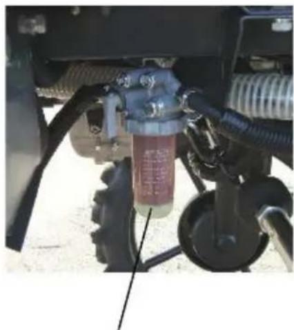
■ Fuel filter
Clean the fuel filter every 100 hours or so of operation, and replace the element every 400 hours.
The cleaning method is as follows:
[1] Close the fuel filter cock.
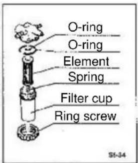
[2] Remove the ring screw and take out the filter cup.
[3] Rinse the element in diesel oil. Also clean the inside of the filter cup with diesel oil.
[4] After the cleaning, assemble the filter cup correctly as before by paying attention not to let dust or dirt attach to the element.
[5] Open the cock.
[6] Bleed air.
natural_image
Close-up of a mechanical assembly with visible gears and hoses, no text or symbols present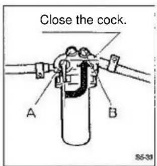
(5) Inspecting the Cooling System

Caution
- If the radiator cap is removed while the engine is hot, hot water gushes out. Wait for the engine to cool and remove the radiator carefully by putting a cloth over it.
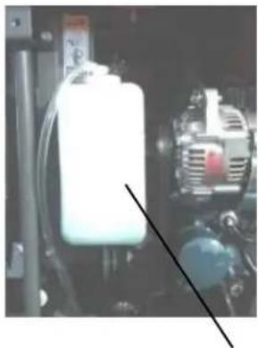
[1] Cooling water level Check the cooling water level based on the amount in the reserve tank. The level is normal if between FULL and LOW. If cooling water is low, add to the FULL level. After cooling water has been added, press the top lid and make sure the lid is securely latched.
natural_image
Close-up of industrial machinery with a white cylindrical component and blue tubing (no visible text or symbols)Reserve tank
* Do not open the radiator cap except when checking and changing cooling water.
* Long-life coolant that does not freeze until -20°C has been charged at the factory prior to shipment. Adjust the concentration of coolant according to the outside air temperature.
-10°C or above 30%
-10 to -25°C 40%
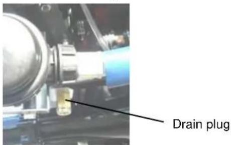
[2] Cleaning the inside of the radiator Open the drain plug and drain cooling water fully. Thereafter, clean the inside with tap water until the flushed water no longer contains rust.
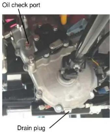
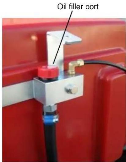
(6) Changing the Auxiliary Transmission Oil Remove the plug on the oil check port and drain plug at the bottom of the auxiliary transmission and drain oil. Add oil from the oil filler port until oil overflows from the oil check port. [Type of oil] Gear oil SAE 90 [Amount of oil] Approx. 2.0 L [When to change] Initial change: 50 hours Periodic change: Every 600 hours

Caution
● After oil has been added, confirm that the drain plug and oil check port plug are securely tightened, and firmly tighten the oil filler cap to prevent loosening.
(7) Changing the Front/Rear Differential Oil
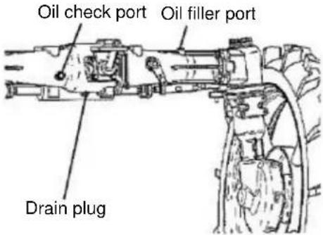
Remove the drain plug and plug on the oil check port to drain oil.
Add oil from the oil filler port until oil overflows from the oil check port.
[Type of oil] Gear oil SAE 90
[Amount of oil] Approx. 1.0 L
[When to change] Initial change: 50 hours
Periodic change: Every 600 hours
(8) Checking the Oil Level in the Hydraulic Oil Tank
Check the oil level using the level gauge provided on the side face of the oil tank. The level is normal if between H and L.
If the level is low, open the oil check port and add oil from the oil filler port until oil overflows from the oil check port.
When changing oil, replace the filter also.
[Type of oil] Hydraulic oil (wear resistant)
VG32
[Amount of oil] Approx. 13 L
[When to change] Initial change: 50 hours
Periodic change: Every 200 hours
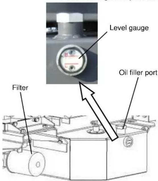
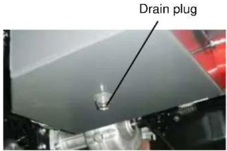
(9) Inspecting the Spray Pump
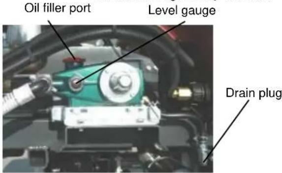
Oil in the crank case
Check if oil is filled to near the center of the level gauge.
If the level is low, add oil from the oil filler port.
To change oil, remove the drain plug and plug on the oil filler port to drain oil.
When filling oil, refuel it from the oil filler port just like when the oil is insufficient.
[Type of oil] SAE 10W-30SJ grade or above
[Amount of oil] Approx. 0.6 L
[When to change] Initial change: 50 hours
Periodic change: Every 100 hours
(10) Greasing
Refer to the Oil Change Table (P. 38)
(11) Adjusting the Belt Tension
[1] Engine HST Loosen the hexagonal bolt and twist the main body until the tensioner mounting angle becomes 15^ . After the adjustment, tighten the hexagonal bolt loosened earlier, to a torque of 43 to 53 N·m.
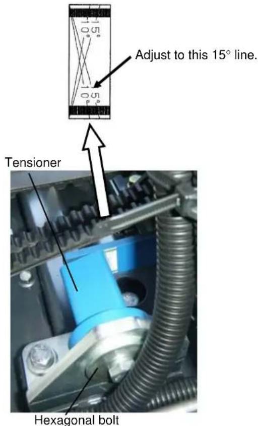
[2] Engine dynamic injection Make adjustment so that when the center of the belt is pressed with a force of 15 to 19 (N), the amount of deflection becomes approx. 5 mm.
(12) Inspecting the Battery

Warning
- Do not use or charge the battery when the battery fluid level is low, because the battery may rupture (explode) or ignite.

Caution
- When inspecting the battery terminals, do not let the terminals get short-circuited.
- When disconnecting the battery cable, be sure to disconnect the negative terminal end first.
- Battery fluid is very corrosive, so do not spill the fluid. If battery fluid attached to your hand, clothes or any metal part, rinse the affected area thoroughly with water.
◆ Maintenance-free battery The battery without top cap is a maintenance-free battery.
[1] Look at the charge indicator vertically.
[2] If the charge indicator is clear or yellow, gently tap the battery to remove air bubbles and then check again.
[3] Take an appropriate action according to the table below based on the indicator color.
| Color | Charge state | Action |
| Green | Normal | The battery can be used. |
| Black | Insufficient | Auxiliary charge is required. |
| Clear | Not enough fluid | Replace the battery if the engine does not start. |
* There is no need to inspect the battery at the start of work.
◆ Conventional battery
[1] Check if the battery fluid level is between UPPER and LOWER. If the level is low, add distilled water to the UPPER level.
[2] After distilled water has been added, securely tighten the cap.
[3] Inspect the battery terminals and if loose, securely tighten the terminals. If white powder is attached to the terminals, clean with hot water and tighten the terminals, and then apply a small amount of grease on the terminals.
Caution
- Do not continue using the machine once the electrolyte level in the battery has dropped to or below the lower limit (LOWER level) indicated on the side face of the battery. Deterioration of each part of the battery cell will be promoted.
■ Method for Long-term Storage
If the machine is not used for a long period of time, follow the care procedure below:
(1) Run through all maintenance and inspection items.
(2) Service problem locations, if any.
(3) Inspect the bolt and nut in each part and tighten them if loose.
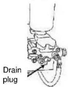
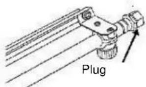
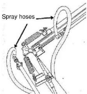
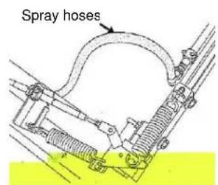
(4) Run the pump at low speed using freshwater and circulate the water for 3 to 4 minutes to clean the inside of the tank, piping, nozzle, etc. To prevent damage caused by freezing, drain all liquid from the spray pump and piping by removing the drain plugs and running the pump idle.
Drain the pump and inside the pipe.
![How to drain water [1] [2] [3]](/content/2026/05/941812/images/7f96b1ab932e8ee3b463542b5e41ff44c79c77fd84d9c02ec2a2d06ad7031ccd.jpg)
[1] Remove the drain plug from the spray pump.
[2] Remove the plugs at the tips of left and right booms.
[3] Disconnect the spray hose at the bases of right and left booms to drain water.
(5) Remove the nozzle cap and drain water remaining inside the nozzle.
(6) Clean the exterior of the machine.
(7) Change engine oil with new oil and operate the engine for around 5 minutes to spread oil to each part.
(8) Be sure to keep the throttle lever in the "Low speed" position.
(9) Fill up the fuel tank with fuel (diesel oil).
(10) Store each boom on the boom receiver.
(11) Use sandpaper, etc., to remove rust from areas where paint has peeled, and apply a fresh coat of paint.
(12) Keep each cock in the "Open" position.
(13) Disconnect the battery cable or remove and store the battery in a dark, dry place.
(14) The battery will self-discharge during storage, so perform auxiliary charge once every month.
(15) Select a dry place for storage and cover the machine with a sheet, etc., to prevent attachment of dust, etc.
(16) Apply grease on the exposed part of each hydraulic cylinder piston rod for boom actuation. Before moving each hydraulic cylinder after storage, wipe off the grease on the piston rod. (If dust attached to the grease enters the cylinder seal, oil may leak.)
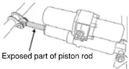
Caution
- The booms will drop gradually due to their dead weights, so do not put objects underneath the booms during a long-term storage.
9 Piping Diagram
[Manual Adjustment Specification]
Piping Diagram
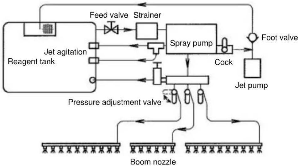
flowchart
graph TD
    A["Reagent tank"] --> B["Jet agitation"]
    B --> C["Feed valve"]
    C --> D["Strainer"]
    D --> E["Spray pump"]
    E --> F["Cock"]
    F --> G["Foot valve"]
    G --> H["Jet pump"]
    H --> I["Boom nozzle"]
    I --> J["Pressure adjustment valve"]
    J --> K["Feed valve"]
    K --> L["Strainer"]
    L --> M["Spray pump"]
    M --> N["Cock"]
    N --> O["Foot valve"]
    O --> P["Jet pump"]
    P --> Q["Boom nozzle"]
Each arrow in the piping diagram indicates the flow direction of water or reagent.
* The jet pump shown in the diagram is optional (sold separately).
10 Causes of Failures and Remedial Actions
Caution
- If the machine malfunctions, be sure to stop the engine, apply the parking brake and remove the ignition key and then diagnose the problem by referring to the table below.
| Phenomenon | Cause | Action | |
| Engine | The starter does not turn when the key switch is turned. | The auxiliary shift lever is not in the "Start" position. | Put the auxiliary shift lever in the "Start" position and then turn the key switch to the "ST" position. |
| Loose or disconnected wire terminal, or loose, disconnected or corroded battery terminal | Retighten or reconnect the terminals. Clean and securely tighten the terminals. Apply grease to prevent rusting. | ||
| Blown fuse | Replace the fuse with new one. | ||
| Low battery voltage | Add battery fluid and charge the battery. Replace the battery. | ||
| Faulty key switch | Contact the dealer where you purchased your machine from. | ||
| Faulty cell motor | Contact the dealer where you purchased your machine from. | ||
| Faulty switch | Contact the dealer where you purchased your machine from. | ||
| The starter turns, but the engine does not start. | No fuel. Air is mixed into fuel. | Add fuel to the fuel tank and bleed air. | |
| Fuel does not flow. | Contact the dealer where you purchased your machine from. | ||
| The battery is almost flat and does not provide enough rotational force to turn the engine. | Charge the battery. If the battery does not charge, replace it with new one. | ||
| Engine revolutions are irregular. | Air has entered the fuel system. | Bleed air. | |
| Water is mixed into fuel. | Drain fuel from the fuel tank/fuel filter and add new fuel. | ||
| Clogged fuel injection nozzle | Contact the dealer where you purchased your machine from. | ||
| Clogged fuel filter | Contact the dealer where you purchased your machine from. | ||
| Engine related | Insufficient engine output | Insufficient fuel | Inspect the fuel system (for entry of air). |
| Clogged air cleaner | Contact the dealer where you purchased your machine from. | ||
| Insufficient compression | Contact the dealer where you purchased your machine from. | ||
| Deterioration of fuel injection state | Contact the dealer where you purchased your machine from. | ||
| Inappropriate intake/exhaust valve gap | Contact the dealer where you purchased your machine from. | ||
| Undesirable exhaust color | Low-grade fuel | Change to high-grade fuel. | |
| Too much engine oil | Adjust the amount of oil to the specified level. | ||
| Deterioration of fuel injection state | Contact the dealer where you purchased your machine from. | ||
| The engine overheated (the water temperature warning lamp turned on). | Insufficient cooling water or leakage of water | Contact the dealer where you purchased your machine from. | |
| Loose fan belt | Contact the dealer where you purchased your machine from. | ||
| Insufficient engine oil | Add oil to the specified level. | ||
| Low engine oil viscosity | Change to oil of appropriate viscosity. | ||
| Faulty pressure switch | Contact the dealer where you purchased your machine from. | ||
| Faulty oil lamp | Contact the dealer where you purchased your machine from. | ||
| The glow lamp does not turn on. | Blown bulb | Replace the bulb with new one. | |
| Blown fuse | Replace the fuse with new one. | ||
| The charge lamp turned on during operation. | Faulty regulator | Contact the dealer where you purchased your machine from. | |
| Loose or damaged fan belt | Contact the dealer where you purchased your machine from. | ||
| Electrical related | A lamp does not turn on. | Blown bulb | Replace the bulb with new one. |
| Blown fuse | Replace the fuse with new one. | ||
| Loose or disconnected wire terminal | Reconnect and retighten after inspection. | ||
| Faulty switch | Contact the dealer where you purchased your machine from. | ||
| The speed is not indicated. | Loose or disconnected wire terminal | Reconnect and retighten after inspection. | |
| Faulty speed sensor | Contact the dealer where you purchased your machine from. | ||
| Pedal related | The clutch does not disengage. | Faulty switch | Contact the dealer where you purchased your machine from. |
| Loose or disconnected wire terminal | Reconnect and retighten after inspection. | ||
| Poor brake effect | Improperly adjusted brake wire | Contact the dealer where you purchased your machine from. | |
| The differential locks only on one side of front and rear wheels. | Improperly adjusted differential lock wire | Contact the dealer where you purchased your machine from. | |
| Lever related | The engine speed drops. | Improperly adjusted throttle lever | Contact the dealer where you purchased your machine from. |
| Gears disengage. | Improperly adjusted shift cable | Contact the dealer where you purchased your machine from. | |
| The HST lever returns. | Faulty lever retention mechanism | Contact the dealer where you purchased your machine from. | |
| The engine does not stop when the HST lever is in the N (Stop) position. | Improperly adjusted cable system | Contact the dealer where you purchased your machine from. | |
| Steering wheel related | The steering wheel is heavy. | Insufficient tire pressure | Adjust the pressure to the reference level. |
| Hydraulic device malfunction | Contact the dealer where you purchased your machine from. | ||
| Steering control is lost. | Uneven pressures of tires | Adjust the pressures of all tires evenly. | |
| Poor straight-rolling property of tire | Contact the dealer where you purchased your machine from. | ||
| Spray device related | The spray amount is small. The pressure does not rise. | No reagent in the tank | Add the required amount of reagent. |
| Closed suction valve | Open the suction valve. | ||
| Low engine speed | Operate the throttle lever to raise the speed. | ||
| Pressure adjustment valve malfunction | Contact the dealer where you purchased your machine from. | ||
| Clogged water absorption strainer | Clean. | ||
| Slipped spray pump belt | Contact the dealer where you purchased your machine from. | ||
| Worn piston gasket, discharge valve or suction valve of the spray pump | Replace the affected part with new one. | ||
| Damaged metal joint gasket of the suction hose or spray hose, or damaged hose | Replace the affected part with new one. | ||
| Worn nozzle | Replace the affected part with new one. | ||
| Clogged nozzle | Clean. | ||
| Poor spray state | Worn or cracked nozzle | Replace the affected part with new one. | |
| Clogged nozzle | Clean. | ||
| Insufficiently tightened nozzle cap | Tighten additionally. | ||
| Damaged metal joint gasket of the suction hose or spray hose, or damaged hose | Replace the affected part with new one. | ||
| Boom device | The boom does not operate. | Loose or detached wire terminal | Reconnect and retighten after inspection. |
| Faulty hydraulic device | Contact the dealer where you purchased your machine from. | ||
| Boom device | Inappropriate sliding condition | Loose or disconnected wiring terminal | Contact the dealer where you purchased your machine from. |
| Excessively taut or slack extend/contract chain or wire | Contact the dealer where you purchased your machine from. | ||
| Slack fixing wire | Contact the dealer where you purchased your machine from. | ||
| Bent or deformed boom | Contact the dealer where you purchased your machine from. | ||
| Defective extend/contract motor | Contact the dealer where you purchased your machine from. | ||
● List of Key Consumables
| Location of use | Item name | Part number | Quantity used | Remarks |
| Engine | Air cleaner element | 647156 | 1 | Kubota 1G659-1122-0 |
| Oil filter | 642984 | 1 | Kubota 15853-3246-0 | |
| V-belt | 577467 | 1 | FM33 | |
| Fuel piping | Filter assembly | 196770 | 1 | Kubota 1G313-43011 |
| Element assembly | 407460 | 1 | Kubota 1G313-43560 | |
| Hydraulic piping | Oil filter | 864679 | 1 | F-903-1 Taisei |
| Harness | Slow-blow fuse | 685844 | 1 | 40A |
| Fuse box | Fuse 30A | 641496 | 1 | |
| Fuse 20A | 191744 | 2 | ||
| Fuse 15A | 185012 | 1 | ||
| Fuse 10A | 641262 | 3 | ||
| Fuse 5A | 191738 | 2 | ||
| Water temperature lamp | Bulb | 595551 | 1 | Meter wedge bulb12V3.4WT10 |
| Oil pressure lamp | Bulb | |||
| Charge lamp | Bulb | |||
| Glow lamp | Bulb | |||
| Spray pump | Piston gasket set | 634031 | 3 | |
| Seal gasket | 100015 | 3 | ||
| Pressure adjustment valve | Sleeve | 117252 | 1 | |
| Piston gasket | 022442 | 1 | ||
| Valve seat | 117251 | 1 | ||
| Traveling gears | V-belt | 864857 | 2 | RCLB47 |
| Pump drive | V-belt | 154393 | 2 | LA41 |

MARUYAMA MFG. CO., LTD.
4-15, Uchikanda 3-chome, Chiyoda-ku, Tokyo TEL 81-3-3252-2285 http://www.maruyama.co.jp
- Introduction
- Specifications
- Table of Contents
- 1
- For Safe Work
- Caution
- Traveling
- Chocking the Tires
- Name of Each Part
- Main Specifications
- ▲ Handling of Warning Labels
- Warning
- Name and Function of Each Device
- ■ Relating to Pest Control [Manual Pressure Adjustment Specification]
- ■ Other
- Tires
- Towing Hooks
- How to Travel/Transport
- ■ How to Start/Stop the Engine
- ■ How to Load/Unload to/from a Truck
- Pest Control Work
- ■ How to Enter/Exit a Field
- ■ How to Feed Water
- ■ Reagent Preparation and Handling
- ■ Spray Inspection
- Opening the Spray Cock and Checking the Spray Condition
- ■ Spray Plan
- Spray Planning
- How to Use the Quick Calculation Diagrams
- "Example"
- [Specifications J]
- [Supplement]
- ■ Spray Method
- ■ Spraying
- ■ After Spraying
- Maintenance
- ■ Inspection Procedures
- Engine Oil
- ■ Fuel tank
- ■ Bleeding air
- ■ Fuel filter
- ■ Method for Long-term Storage
- Piping Diagram
- Causes of Failures and Remedial Actions
- MARUYAMA MFG. CO., LTD.
Brand : Maruyama
Model : BSA-500
Category : Uncategorized