BSM201 - Uncategorized Maruyama - Free user manual and instructions
Find the device manual for free BSM201 Maruyama in PDF.


| Product Type | Boom Sprayer for Tractor Mounting |
| Model | BSM201-3JP (3-point hitch specification) |
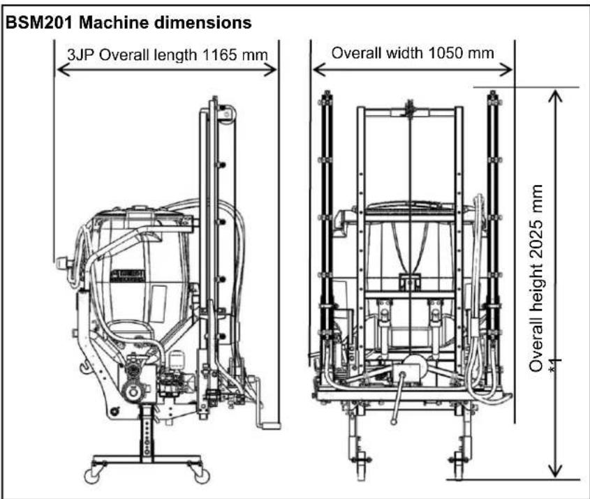
| Dimensions (L x W x H) | 1165 x 1050 x 2025 mm (stand at highest, min 1925 mm) |
| Dry Mass | 115 kg |
| Reagent Tank Capacity | Nominal 200 L, Max 210 L |
| Spray Pump Model | MS331 |
| Pump Max Pressure | 3.0 MPa |
| Pump Flow Rate | 30.0 L/min |
| Pump RPM | 1050 rpm |
| Number of Nozzles | 14 (Wide-angle Kirinashi N-KA-8R) |
| Total Spray Amount at 1.5 MPa | 15.4 L/min |
| Spray Width | 4.2 m |
| Spray Height Range | 0.4 to 1.5 m |
| Agitation Method | Spillway and jet agitation |
| Boom Type | Two-boom folding type, manual vertical storage |
| Recommended Tractor | 17-23 PS class, Category 0 or 1, 3-point link |
| PTO Speed Range | 440-615 rpm |
| Stand | Height adjustable, with casters and lock |
| Included Accessories | Universal joint, parallel key, bolts, hex wrench, manuals |
| Safety Features | Warning labels, protective gear instructions, tire chocks required |
| Maintenance Interval | Oil change every 100 hours, clean strainers and filters after each use |
| Long-term Storage | Drain system, apply anti-rust, store in dry place |
Frequently Asked Questions - BSM201 Maruyama
User questions about BSM201 Maruyama
0 question about this device. Answer the ones you know or ask your own.
Ask a new question about this device
Download the instructions for your Uncategorized in PDF format for free! Find your manual BSM201 - Maruyama and take your electronic device back in hand. On this page are published all the documents necessary for the use of your device. BSM201 by Maruyama.
USER MANUAL BSM201 Maruyama
natural_image
Technical line drawing of a mechanical spray gun system with conveyor belt and control panel (no text or symbols)Please Read This Document Before Use.
Introduction
Thank you for purchasing a Maruyama product. This Operation Manual explains the correct handling of the product and how you can easily inspect and care for it, so that you can carry out your work safely and comfortably using the machine.
Before using the product, read this manual carefully and understand the contents fully so that the product will continue to demonstrate excellent performance.
After reading this manual, keep it in a safe place and reference it every time you have a question.
Please note that information contained in this manual may not exactly match the product you purchased due to specification changes of the product, etc.
If you have any feedback on this product, please contact the Maruyama dealer or sales office near you.
■ Scope of Use
This product is designed for spraying herbicide and controlling pests in crop fields.
Maruyama shall assume no responsibility for any accident caused by using the product outside the foregoing scope of use or accident arising from an unauthorized modification or disassembly.
■ Precautions
The precautions contained in this manual and warning labels bearing ⚠️ you see on the machine provide important items that may cause injury if neglected. Read these precautions and labels carefully and be sure to follow the instructions.
In this Operation Manual, particularly important handling precautions are denoted as follows:
Danger --- Failure to follow this instruction will lead to death or serious injury.
Warning --- Failure to follow this instruction may lead to death or serious injury.
Caution --- Failure to follow this instruction may lead to injury.
Caution ---Failure to follow this instruction may lead to machine damage.
■ Lending the Machine to a Third Party
Before lending the machine, teach the person how to operate the machine and also explain one by one the warning labels with the " 🔊" mark attached on the machine. Pass this Operation Manual/Safety Manual together with the machine and instruct the user to carefully read these manuals to understand the contents and get the hang of handling the machine, so that your friendly gesture will not turn into a tragedy. In particular, spend time explaining the prohibited items. Explain the same to other family members who have not received the instructions at the time of delivery.
International Units
● This Operation Manual uses international units. Carefully read the table below to understand the conversion values before use.
Conversion Table
| Quantity | Unit indication under new measuring system | Conversion | Conventional unit indication | Remarks |
| Area | [m2] (square meters) | 10000 [m2] = 1 [ha] = 100 [a] = 10 tanbu (1 tanbu = 10a) = 3000 tsubo (approximately 1 tsubo=3.3 m2) | [a] (are), [ha] (hectare)Tsubo (approximately 1 tsubo=3.3 m2), chobu (1 chobu = 100 a), tanbu (1 tanbu = 10 a) | *[1] |
| Rotational speed | [rpm] (revolutions per minute)[min-1] (per minute) | 1 [min-1] = 1 [rpm] | [rpm] | *[2] |
| Force | [N] (Newton) | 9.8 [N] = 1 [kgf] | [kgf] (weight kilogram) | |
| Moment of force | [N·m] (Newton meter) | 9.8 [N·m] = 1 [kgf·m] | [kgf·m] | |
| Pressure | [Pa] (Pascal) | 0.98 [MPa] = 10 [kgf/cm2]9.8 [Pa] = 1 [mmH2O] | [kgf/cm2][mmH2O] | |
| Work ratio/drive power | [W] (watt) | 735.5 [W] = 1 [PS]9.8 [W] = 1 [kgf·m/s] | [PS][kgf·m/s] |
* Notes
[1] [a] and [ha] may be used to indicate land areas.
[2] The number of revolutions per unit time is indicated as “rotational speed” not as “revolutions.”
Table of Contents
1 For Safe Work.... 3
2 Name of Each Part and Accessories 5
3 Main Specifications....6
4 Handling of Warning Labels....8
5 Preparing the Stand.... 10
6 Installing/Removing the Boom Sprayer on/from the Tractor....11
■ Installing the Boom Sprayer on the 3-point Link Tractor 12
7 How to View/Use Each Unit.... 13
■ Reagent tank....13
■ Jet nozzle....13
■ Water absorption strainer/feed valve 14
■ Spray pump....14
■ Pressure adjustment dial ....15
■ Spray cock ....15
■ Mast frame....15
■ Boom device 16
(1) How to Open/Close the Side Boom 16
(2) How to Use the Winch and Adjust the Spray Height.... 18
8 Spray Plan 20
9 Startup Inspection.... 22
10 How to Feed Water 22
11 Spray Inspection 22
12 Precautions for Spraying 24
13 Reagent Preparation.... 24
14 Spray Method 24
15 Stopping the Spraying 25
16 After Spraying 25
17 Maintenance and Inspection....26
■ Mounting bolt/nut 27
■ Side boom....27
■ Water filter net 27
■ Water absorption strainer 28
■ Reagent piping connections 28
■ Nozzle....28
■ Jet nozzle....28
■ V-belt 28
■ Winch....28
18 Lubricant List 29
19 Long-term Storage....30
20 Piping Diagram 31
21 Troubleshooting 32
22 List of Key Consumables 33
1
For Safe Work
(1) Overview
Carefully read the "Operation Manual" and instruction manual of the agrichemical used, to carry out work correctly and safely.
[1] When using the boom sprayer installed on the tractor, make sure it is not tilted more than 5^ .
[2] The person performing spraying should wear protective gears for agrichemical spraying (such as a pest control mask, protective glasses, boots, rubber gloves and waterproof protective cloth, etc.) to prevent the reagent from coming in direct contact with the body.
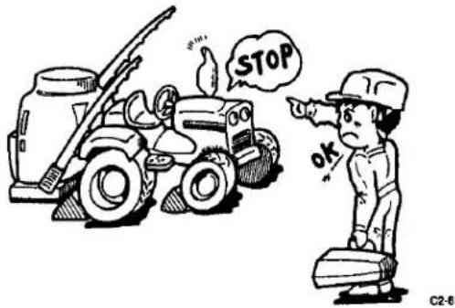
[3] Inspect/service and repair the boom sprayer on flat ground. To inspect/service the boom sprayer while still installed on the tractor, stop the engine on flat ground, apply the parking brake, remove the key, and extend the boom sprayer stand. Failure to do so may cause the tractor to move unexpectedly, resulting in an accident.
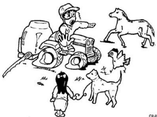
[5] Keep non-operators away from the area where pest control work is performed. Failure to do so may lead to an accident.
[6] Exercise due caution not to pollute water supply systems, rivers, lakes, ponds, etc.
[7] Never refuel near a fire source as it may cause fire. Refueling while smoking is strictly prohibited.
natural_image
Cartoon illustration of a person pulling a dog with a horse nearby (no text or symbols)(2) Precautions When Installing the Boom Sprayer on the Tractor
[1] Carefully read the operation manual for the tractor to familiarize yourself with the tractor operation.
[2] On flat ground, completely stop the tractor engine, PTO, etc., and be sure to perform startup inspection on the tractor and boom sprayer to prevent problems during pest control work. Startup Inspection: Page 22
[3] No one should stand between the tractor and boom sprayer. It may result in a serious accident.
[4] Securely connect the universal joint. Failure to do so may lead to malfunction.
[5] Strictly observe the instructions provided in the operation manual for the boom sprayer as to which tractor you can use to install the boom sprayer. It should be noted, however, that the overall weight and front-rear weight balance vary depending on the tractor. Put weights on the front side so that the loads applied to the steering wheels (front wheels) of the tractor will become 20% or more of the overall weight. If the weights are not balanced, the front wheels of the tractor will lift from the ground and cause an accident.
(3) Driving
Clean water is sprayed for adjustment of spray pressure and spray check.
[1] Before driving the tractor, check the connection of the universal joint, etc. again, and installation of the options, etc.
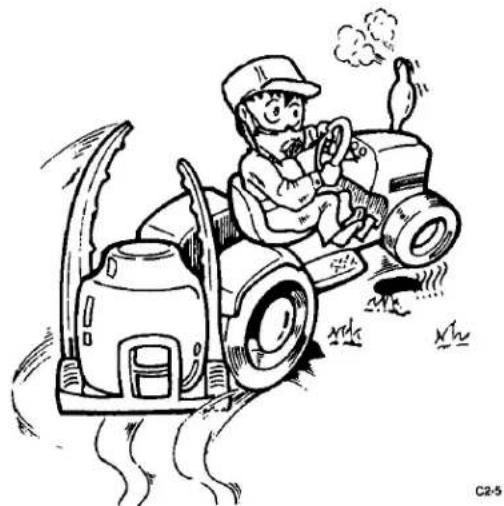
[2] Do not increase the speed more than necessary and avoid sudden take-off, acceleration, braking or turning, to drive and work safely.
[3] When moving to a field or between fields, be sure to keep the boom closed (page 16).
[4] Always confirm safety when entering/exiting a field, crossing a channel or ditch between fields, or traveling on soft terrain, etc.
[5] Climb uphill in reverse gear to prevent the tractor from back-flipping.
Depending on how full or empty the reagent tank is, the center-of-gravity position may change to make the tractor unstable; accordingly, pay due attention to safety especially after filling the reagent tank.
natural_image
Cartoon illustration of a farmer operating a tractor with smoke and steam, no text or symbols present(4) Storage
[1] Store the boom sprayer safely on flat ground after inspecting/servicing the boom sprayer and with the boom sprayer stand extended.
[2] To store the boom sprayer while still installed on the tractor, be sure to extend the boom sprayer stand and lower the boom sprayer.
(5) Chocking the Tires
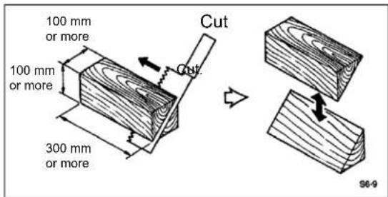
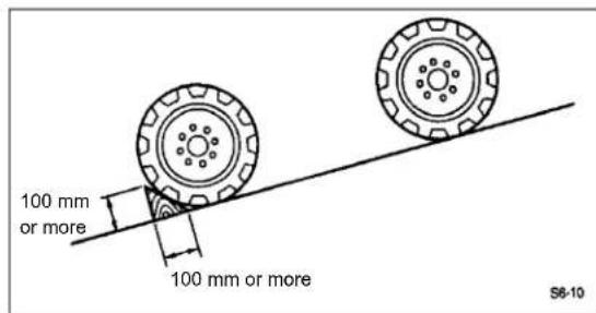
Prepare concrete blocks, wooden blocks or other objects (10x10 cm or larger, 30 cm or longer) that can be used to chock the tires so that the tractor can be parked safely. Chock the bottom side of tires on the two wheels, one left and one right, on the lower side of the incline.
2
Name of Each Part and Accessories
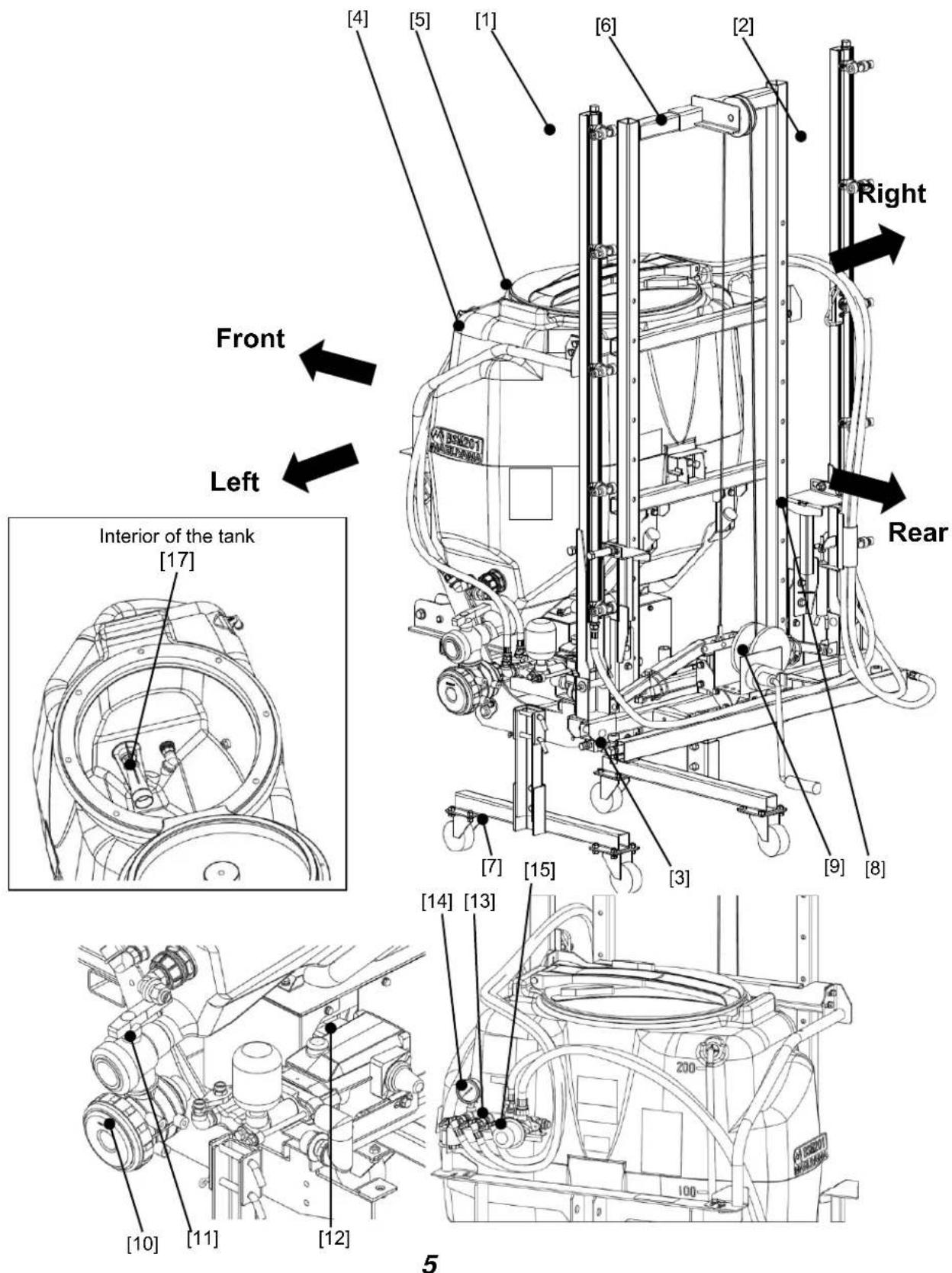
BSM201-3JP (3P hitch specification)
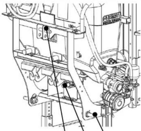
[18] [16] [19]
■ Name of Each Part and Accessories
| No. | Name | Reference page in the manual |
| [1] | Left boom (side boom) | 16 |
| [2] | Right boom (side boom) | 16 |
| [3] | Center boom (center boom) | 18 |
| [4] | Reagent tank | 13 |
| [5] | Reagent tank lid | 13 |
| [6] | Mast frame | 15 |
| [7] | Stand | 10 |
| [8] | Boom receiver | 16 |
| [9] | Winch | 18 |
| [10] | Water absorption strainer | 14, 24, 25, 26, 28, 30, 32, 33 |
| [11] | Feed valve | 14, 22, 24 |
| [12] | Spray pump | 14, 26, 29, 31, 32, 33 |
| [13] | Spray cock | 15, 22, 25, 30 |
| [14] | Pressure gauge | 15 |
| [15] | Pressure adjustment dial | 15, 22, 24, 31 |
| [16] | Input shaft | 11, 26 |
| [17] | Jet nozzle | 13, 26, 28, 33 |
| [18] | Lower link pin | 12 |
| [19] | Top link pin (*1) | 12 |
*1 For the top link pin and the linchpins for fixing the top link, use the accessories that came with the tractor.
■ Accessories
| Name | Part number | Quantity | Remarks | |
| Operation Manual | ****** | 1 | This manual | |
| Assembly Procedures | 567600 | 1 | ||
| Safety Operation Manual | 177230 | 1 | ||
| Warranty Card | - | 1 | ||
| Universal joint | 3JP | 153672 | 1 | |
| Parallel key | 567460 | 1 | 7x7x45 (for mounting the universal joint) | |
| Hexagonal bolt | 567461 | 1 | M10x35 (for mounting the universal joint) | |
| Hexagonal nut | 567143 | 1 | M10 (for mounting the universal joint) | |
| Flanged bolt | 567065 | 4 | M10x25 Flanged bolt (for assembling the stand) | |
| Hex wrench | - | 1 | For detaching/attaching the winch handle | |
3 Main Specifications
| Name | BSM201 | |
| 3JP | ||
| Machine dimensions (length x width x height) mm | 1165X1050X2025 *1 | |
| Dry mass (kg) | 115 | |
| Spray pump | Model | MS331 (BSM201) |
| Rotational speed (rpm) | 1050 | |
| Water absorption (L/min) | 30.0 | |
| Maximum operating pressure (MPa) | 3.0 | |
| Spray device | Type | Two-boom folding type |
| Storage method | Manual storage in vertical position | |
| Reagent tank | Nominal capacity (L) | 200 |
| Maximum capacity (L) | 210 | |
| Agitation method | Spillway and jet agitation | |
| Nozzle | Name | Wide-angled Kirinashi nozzle |
| Model | N-KA-8R | |
| Quantity | 14 pcs | |
| Normal operation pressure (MPa) | 1.5 | |
| Total spray amount (L/min, 1.5 MPa) | 15.4 | |
| Spray width (m) | 4.2 | |
| Spray height (m) | 0.4 to 1.5 | |
| Tractor *5 | Type | As a rough guide, use a 17 to 23-ps class tractor of category 0 or 1.*4 |
| Installation method | 3-point link | |
*1 Height when the stand is adjusted to the highest level. 1925 mm when the stand is at the lowest level.
*2 Be sure to place 75 kg of weights on the front.
*3 Installation may not be possible depending on the functions (horizontal control function, etc.) of the tractor.
*4 Place weights on the front as necessary. Also note that installation may not be possible depending on the tractor.
Consult the Maruyama dealer near you.
*5 The applicable tractors are subject to change.
■ The specifications are subject to change without notice for the purpose of improvement.
4
Handling of Warning Labels

Warning
- Constantly remove soiling and mud over the labels so that the information provided on them remains visible.
- If you find a damaged warning label, order a new label from the Maruyama dealer near you and replace the old label.
- If a part on which a warning label is attached has been replaced, be sure to attach a new label on the new part at the same location.
* The warning labels shown below are attached on this machine. Before commencing work, carefully read and understand these labels. Carefully read the information provided on the labels as described below.
![[1] 200 [2] 100 [3]](/content/2026/05/941810/images/c734bbfc2503e047815b0b0712a7f9438ab610f77dd5db7319582182f4fb1cad.jpg)
[1] P/N: 567345

Warning
- Wear clothes that properly fit your body. Prepare protective clothes, pest control mask, protective goggles, rubber gloves, work shoes (boots), etc., and dress safely during work.
- Never feed water directly from a drinking water source or any lake or pond used for aquatic farming.
- Make the spray planning so that there won't be any reagent left.
• Make sure the reagent tank is empty when installing or removing the sprayer. - Avoid sudden take-off, turning or braking to prevent a tip-over.
P/N. 567345
[2] P/N: 567591

When installing the universal joint, stop the engine of the tractor, remove the key, apply the parking brake, and always turn off the PTO clutch.
P/N. 567591
[3] P/N: 567593
Caution
If the lower link (or lift arm if the machine is of the two-point link specification) is raised excessively, it may cause contact with the tractor and damage the tractor or boom sprayer.
P/N. 567593
![[4]](/content/2026/05/941810/images/7de7c00d50ef5b5a8be6cecd978038edbc843cef5ba0a81a6d65a59d7e914568.jpg)
[4] P/N: 567595
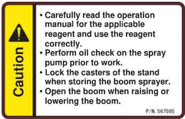
5
Preparing the Stand
Use this to install or remove the boom sprayer.

Warning
● To remove the stand, pull out the pin while holding the stand by hand and then remove the stand slowly.
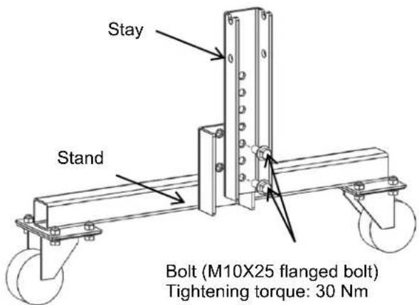
(1) How to Assemble the Stand
Connect the stand and the stay with the bolts.
The bolts are provided as accessories.
The height of the stand can be adjusted using the holes in the stay.
Adjust the height according to the applicable tractor.
(2) How to Install the Stand
[1] Insert the stand into the stay on the machine.
[2] Insert the stand pin and install the snap pin.
[3] Move the stand to the left and right to check if it is firmly locked.
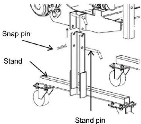
[4] Remove the stand by following the installation procedure in the reverse order.
(3) How to Use the Caster Lock
The stand has casters.
The casters have a lock mechanism. Operate the lock mechanism with your foot. Lower the mechanism to lock the caster, or raise it unlock the caster.
For safety reasons, keep the casters locked except when the boom sprayer is moved.
6
Installing/Removing the Boom Sprayer on/from the Tractor

Warning
- For safety reasons, one person should work alone to install or remove the boom sprayer on/from the tractor.
- When installing or removing the boom sprayer on/from the tractor, make sure the reagent tank is empty and the boom is closed. If the reagent tank contains reagent or water or the boom is open, the center of gravity may shift and cause an accident.
- When installing or removing the boom sprayer on/from the tractor, choose a location where the ground is flat and the casters are not buried.
- For the tractor on which to install the boom sprayer, follow the models specified in the main specifications. Weights must be prepared separately to be placed on the front. Spray without weights on the front may make the tractor unstable and tip over. Before commencing work, check with the dealer you purchased your machine from.
Caution
● The two-link specification cannot be installed on a tractor with horizontal control function.
- If the tractor has pumper function, turn it off during work. Failure to do so may cause the boom sprayer to rise unexpectedly and create a dangerous situation.
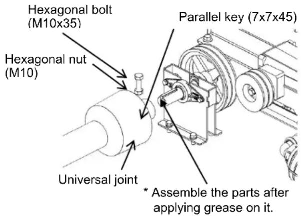
How to Install the Universal Joint
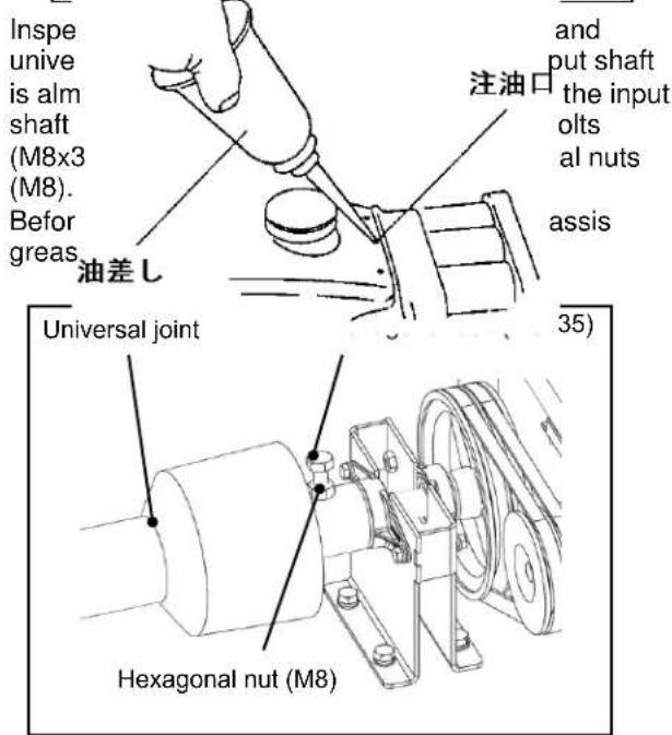
1) Install parallel keys on the input shaft, apply grease, and insert the universal joint all the way to the end (until it contacts the step on the input shaft).
2) Assemble the supplied hexagonal bolt and hexagonal nut, and screw the bolt all the way into the female thread of the universal joint, to secure the universal joint.
3) Lastly, tighten the hexagonal nut to lock the bolt.
■ Installing the Boom Sprayer on the 3-point Link Tractor
Preparing the Tractor
[1] Align the heights of the left and right lower links on the tractor. For the operating method, refer to the operation manual for the tractor.
[2] Install the top link on the tractor.
Installing the Boom Sprayer on the Tractor
[1] Unlock the casters of the stand and slowly bring the boom sprayer to the tractor by aligning its position and orientation with the center of the tractor.
[2] Align the position of the left lower link with that of the lower link pin on the boom sprayer.
Caution
- If the right lower link contacts the machine and the left lower link does not rise, adjust and open the right stabilizer until the right lower link no longer contacts the machine. Otherwise, your hand may get pinched and injured.
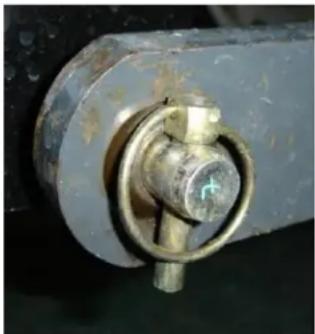
[3] Insert the left lower link on the tractor over the lower link pin and lock it with the linchpin.
natural_image
Close-up of a metallic mechanical component with a brass fitting and bolted joint (no visible text or symbols)* The lower link pin is locked.
[4] Insert the right lower link pin and lock it with the linchpin. (The right lower link moves up and down when the adjustment handle is turned.)
Caution
- Adjust the left/right balance by turning the right lower link adjustment handle, until the links are level. (Refer to the operation manual for the tractor.)
[5] Apply the parking brake on the tractor and confirm that the PTO is OFF, and then start the engine, slowly raise the lower link, install the top link on the boom sprayer, and secure it with the linchpin. Adjust the length of the top link with the lower links at the work height, until the machine is level.
- For the top link pin and the linchpins for fixing the top link, use the accessories that came with the tractor.
Warning
● Operate the lower link of the tractor as carefully and slowly as possible. Also make sure no one stands between the tractor and machine under any circumstance. Abruptly moving the lower link may cause the machine to suddenly approach the tractor or flip back, resulting in a serious accident.
Caution
- If the lower link is raised excessively, they may contact the tractor and damage the tractor or boom sprayer.
[6] Stop the tractor engine and install the universal joint on the tractor's PTO shaft.
Warning
- When installing the universal joint, stop the engine of the tractor, apply the parking brake, and be sure to turn off the PTO.
* Apply grease on the PTO output shaft of the tractor.
[7] Adjust the stabilizer of the tractor lower link to secure the boom sprayer.
[8] Confirm that the boom sprayer has been installed completely, and then remove the stand.
7
How to View/Use Each Unit
■ Reagent tank
A container in which to store mixed reagent. The maximum capacity is 210 L.
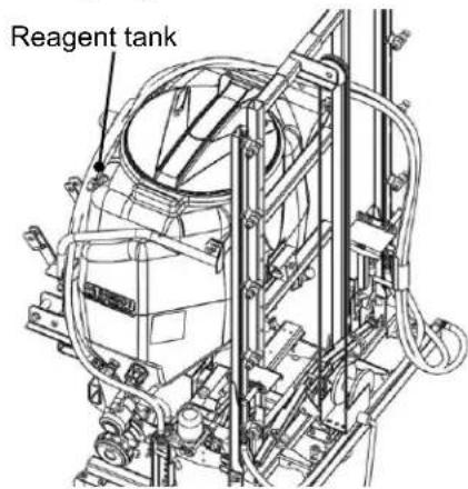
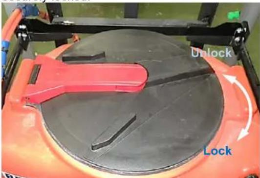
To open the lid of the reagent tank, turn it counterclockwise to unlock and open the lid. To close the lid, turn it clockwise until the lid is securely locked.
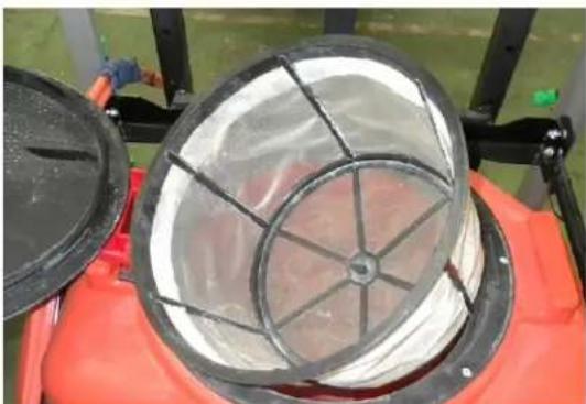
The water filter net in the reagent tank filters out contaminants when feeding water or mixing reagent.
Caution
● Clean the water filter net after each session. Pull out the water filter net.
natural_image
Close-up of a red industrial machine with a circular duct containing white insulation and black frame (no visible text or symbols)A level gauge is provided on the left side of the reagent tank. When checking the level in the reagent tank, make sure the machine is level.
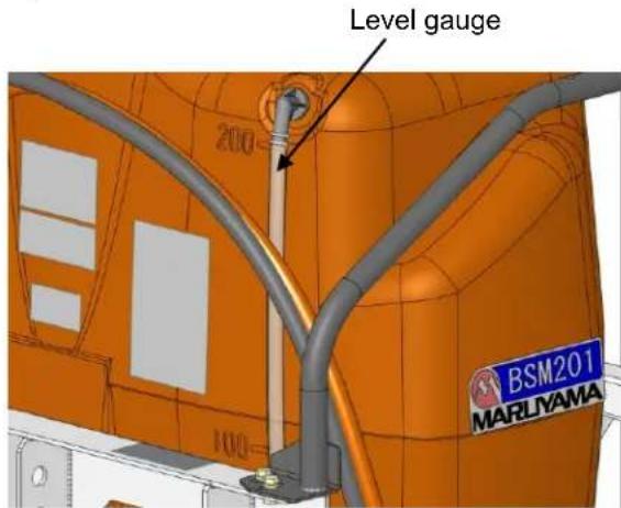
Caution
- If the tractor is driven when the reagent tank is full, reagent may overflow. Keep the reagent level to 200 L or less.
■ Jet nozzle
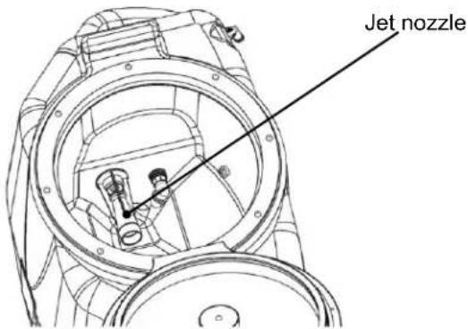
This nozzle is used to create jet flows to agitate the reagent in the reagent tank.
Caution
- A clogged jet nozzle may lead to improper agitation of the reagent and possible chemical damage. - Replace a worn jet nozzle because once the jet nozzle is worn, the pump can no longer demonstrate its designed performance, preventing the pump pressure from rising, causing the spray amount to decrease, and so on.
■ Water absorption strainer/feed valve
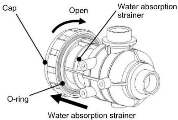
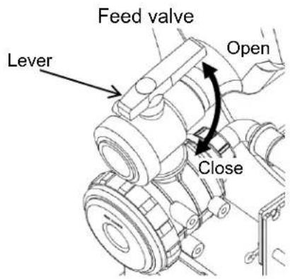
The water absorption strainer filters out contaminants that have entered reagent tank. The strainer can be removed from the water absorption strainer by loosening the cap. If reagent remains in the reagent tank, close the feed valve first before cleaning the strainer.

Warning
- If the water absorption strainer is removed while reagent still remains in the reagent tank or the feed valve is open, reagent may spout out onto you or flow out unexpectedly.
- When removing the water absorption strainer, reagent will still come out of the water absorption strainer and reagent piping even when the feed valve is closed; accordingly, prepare a container to collect the reagent in order to prevent reagent from flowing outside.
- Be sure to keep the feed valve open while the spray pump is running. If the spray pump is run with the feed valve closed, the spray pump may be damaged.
● Clean the water absorption strainer after each session. After the cleaning, securely tighten the cap.
■ Spray pump
This pump is used to suction and pressure-feed reagent in the reagent tank.
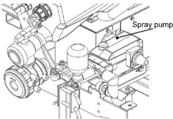
Caution
- Be sure to use the PTO of the tractor at speeds between 440 and 615 rpm. If the PTO speed is too high or too low, uneven spraying or spray pump malfunction may result.
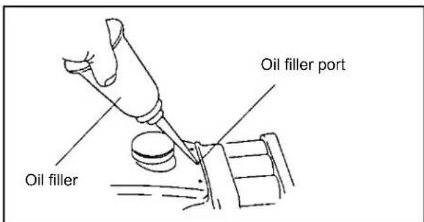
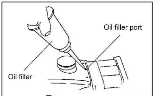
● After every 100 hours of operation, put around 3 to 5 drops of oil (SAE 10W-30 SJ class or higher) into the three holes (oil filler ports) shown in the figure.
■ Pressure adjustment dial
Adjust the discharge pressure of the spray pump. Turn the pressure adjustment dial clockwise to raise the pressure, or turn it counterclockwise to lower the pressure. Check the discharge pressure on the pressure gauge.
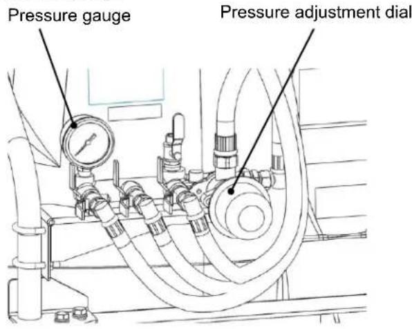
To stop spraying or end the spraying session, turn the pressure adjustment dial counterclockwise until it stops, to lower the pressure, and then turn off the PTO.
■ Spray cock
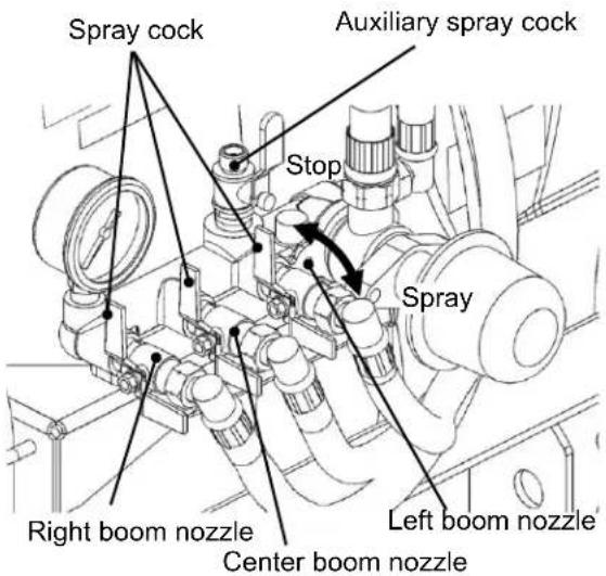
Reagent is sprayed from the nozzle when the spray cock is in the "Open" position, and spraying stops when the cock is in the "Close" position. The left boom nozzle, center boom nozzle and right boom nozzle can be operated separately.
An auxiliary spray cock is also available. You can connect existing nozzles you may have. (The hose diameter is 8.5 mm, and the thread size is G1/4.)
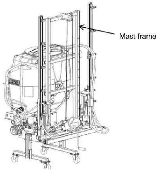
■ Mast frame
The center boom is installed on this frame. The spray height can be adjusted by changing the installation position of the center boom. Refer to page 18 for information on how to adjust the spray height.
■ Boom device
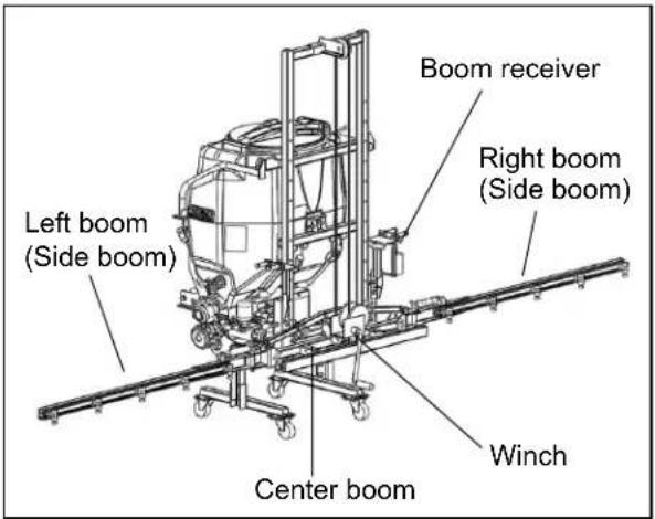
Reagent is sprayed from the nozzle. The 3-piece split boom consists of the left boom (side boom), center boom and right boom (side boom), of which the side booms can be folded up vertically. The booms are operated manually.
The center boom can be moved up and down with the winch.
(1) How to Open/Close the Side Boom
Caution
- When opening/closing the boom, check if any obstacle is present within the 5-m radius.
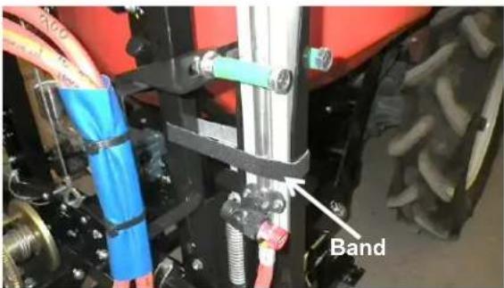
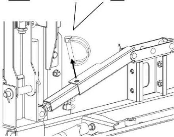
[1] Remove the band securing the side boom on the boom receiver.
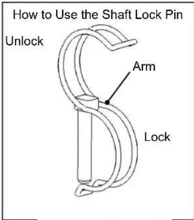
[2] Pull up the arm of the shaft lock pin securing the side boom, to unlock the pin.
[3] Hold the side boom by one hand to keep it from moving unexpectedly, and pull out the shaft lock pin with the other hand.
natural_image
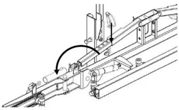
Technical line drawing of a mechanical assembly with no visible text or symbols[4] Open the side booms so that they lie horizontal, and align the top and bottom pin holes and insert the shaft lock pin.
natural_image
Technical line drawing of a mechanical assembly with no visible text or symbols[5] Lower the arm of the shaft lock pin to lock the pin.
Caution
- Be sure to lock the shaft lock pin with the arm.
[6] Close the side boom by following the opening procedure in the reverse order.
Caution
- When closing the side boom, be sure to store the side boom in the boom receiver.
- When the machine is stored or moved, be sure to store the boom in the boom receiver and secure it with the band. If the tractor is driven without storing the boom in the boom receiver, the boom or boom receiver may be damaged.
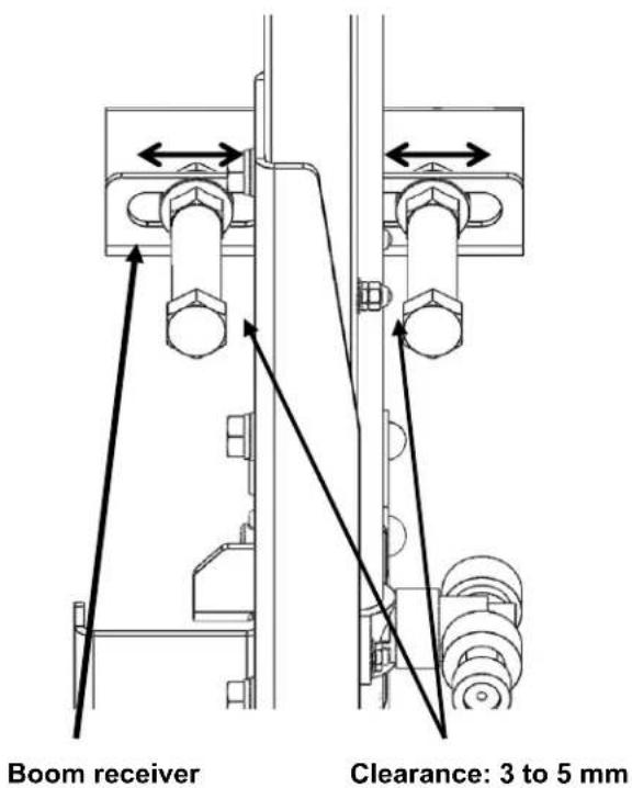
- Confirm that, when the side boom is stored in the boom receiver, a clearance of 3 to 5mm remains between the boom receiving bolt and the side boom. If the clearance is too big, loosen the bolt and adjust the clearance to between 3 and 5mm . If the clearance is too big, the side boom may move about and get damaged.
- When the machine is unpacked, you find that the winch is installed in reverse. Refer to the supplied assembly procedures and reinstall the winch before use.
(2) How to Use the Winch and Adjust the Spray Height
By operating the winch installed on the center boom, the spray height can be changed by 10 cm at a time according to the height of the target grass.
The maximum spray height is 1.5 m.
The machine has been shipped with the handle detached. To use the winch, install the handle. Align the concaves on the shaft with the bolts of the handle, and insert the handle.
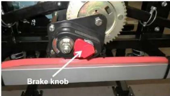
The handle can be installed only when the brake knob is in the ON position. (The factory-set knob position is ON.)
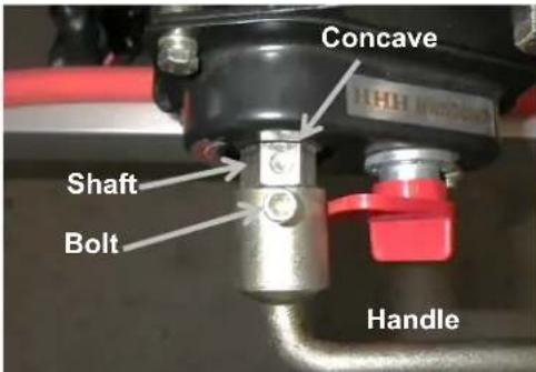
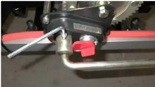
Securely tighten the bolts using the supplied hex wrench.
Tighten the two bolts alternately and evenly.
As a rough guide for the tightening torque, tighten the bolt until the tip of the bolt makes contact, and then tighten it further by one-quarter of a turn. The bolt on the opposite side should be turned further by one-eighth of a turn.
natural_image
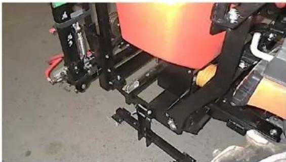
Close-up of a mechanical assembly with metal components and a red handle (no visible text or symbols)The handle can be removed by following the installation procedure in the reverse order. Store the removed handle in the place where the frame is stored.
natural_image
Close-up of a mechanical assembly with black frame and orange component (no visible text or symbols)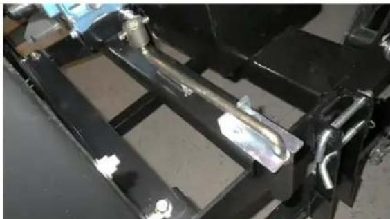
natural_image
Close-up of a metal frame structure with bolts and bolts, no visible text or symbolsAdjust the height of the center boom according to the explanation below.

Caution
- When changing the spray height, check if any obstacle is present within the 5-m radius.
[1] Confirm that the hydraulics of the tractor are locked.
[2] Apply the parking brake on the tractor, stop the engine, and remove the key.
[3] Remove the shaft lock pins securing the center boom on the mast. (2 locations on the left and right.)
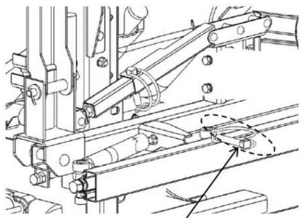
natural_image
Technical line drawing of a mechanical assembly with no visible text or symbolsShaft lock pin
[4] Turn the handle of the winch to adjust the center boom to a desired height.
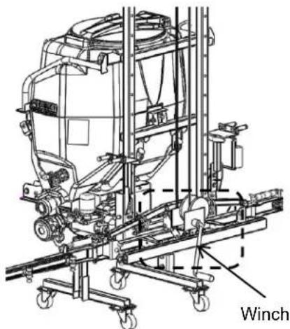
natural_image
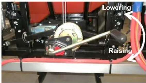
Technical line drawing of a winch machine with conveyor system and wheels (no text or symbols)Turning the handle clockwise raises the center boom. (Reeling in the wire)
Turning the handle counterclockwise lowers the center boom. (Reeling out the wire)
The center boom will not drop even when the hand is taken off the handle.
[5] Secure the center boom with the shaft lock pins removed in [3].
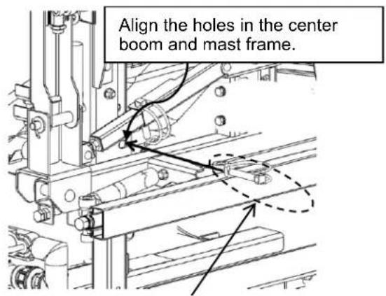
Shaft lock pin
Caution
● Change the spray height with the left and right booms open.
● The winch has a built-in brake mechanism. Do not disassemble the brake, as it may cause malfunction.
- Be sure to use the supplied handle to operate the winch.
Do not use a spanner, ratchet handle, etc., to operate the winch instead of the handle. Doing so may result in improper brake operation, causing the reel drum to spin and the center boom to drop.
- Do not lubricate the brake part of the winch. The brake will no longer operate properly.
● Push in the brake knob on the winch and turn the knob counterclockwise to release the brake.
Do not operate the brake knob, because the center boom may drop and create a dangerous situation.
● While the machine is moved/tractor is driven, remove and store the handle of the winch.
- If the tractor is driven without the center boom secured with the shaft lock pins, the winch may be damaged and the center boom may drop.
8
Spray Plan
Before actually commencing work, set a spray plan for the day.
- Select a nozzle so that the total spray amount from the nozzle will not exceed 23.5 L/min. If this amount is exceeded, the spray pump may encounter problems.
- Use the machine at spray pressures in a range of 0.5 to 1.5 (MPa). If the pressure is too high, the nozzle may be damaged; if the pressure is too low, uneven spraying may result.
● Make sure the spray speed is 3 km/h or less. If the speed is too high, the machine may receive excessive load and get damaged.
[1] In spray planning, determine the spray amount per unit area (spray amount per 10 a) first, and then select the spray speed and obtain the spray pressure.
[2] An appropriate spray speed is the speed of a person walking slowly (approx. 2 km/h).
[3] Determine the traveling velocity and spray pressure by using the quick reference guide on spray speeds.
A quick reference guide showing representative spray speeds on tractors is shown.
Quick Reference Guide on Spray Speeds JB17, 19
| Spray amount per 10 a | Spray pressure | ||
| 0.5 MPaTotal spray amount 10.1[L/min] | 1 MPaTotal spray amount 14.4[L/min] | 1.5 MPaTotal spray amount 18[L/min] | |
| 50 L | 2.5 km/h | ||
| 60 L | 2.1 km/h | 3.0 km/h | |
| 70 L | 1.8 km/h | 2.6 km/h | |
| 80 L | 1.6 km/h | 2.3 km/h | 2.8 km/h |
| 90 L | 1.4 km/h | 2.0 km/h | 2.4 km/h |
| 100 L | 1.3 km/h | 1.8 km/h | 2.2 km/h |
Reference Graph for Spray Planning (N-KA-8R)
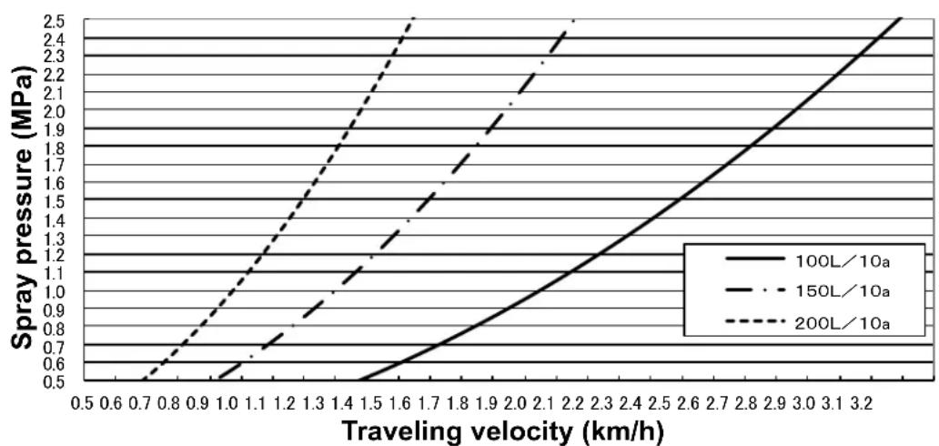
line
| Traveling velocity (km/h) | 100L/10a | 150L/10a | 200L/10a | | ------------------------- | -------- | -------- | -------- | | 0.5 | 0.5 | 0.5 | 0.5 | | 0.6 | 0.6 | 0.6 | 0.6 | | 0.7 | 0.7 | 0.7 | 0.7 | | 0.8 | 0.8 | 0.8 | 0.8 | | 0.9 | 0.9 | 0.9 | 0.9 | | 1.0 | 1.0 | 1.0 | 1.0 | | 1.1 | 1.1 | 1.1 | 1.1 | | 1.2 | 1.2 | 1.2 | 1.2 | | 1.3 | 1.3 | 1.3 | 1.3 | | 1.4 | 1.4 | 1.4 | 1.4 | | 1.5 | 1.5 | 1.5 | 1.5 | | 1.6 | 1.6 | 1.6 | 1.6 | | 1.7 | 1.7 | 1.7 | 1.7 | | 1.8 | 1.8 | 1.8 | 1.8 | | 1.9 | 1.9 | 1.9 | 1.9 | | 2.0 | 2.0 | 2.0 | 2.0 | | 2.1 | 2.1 | 2.1 | 2.1 | | 2.2 | 2.2 | 2.2 | 2.2 | | 2.3 | 2.3 | 2.3 | 2.3 | | 2.4 | 2.4 | 2.4 | 2.4 | | 2.5 | 2.5 | 2.5 | 2.5 | | 2.6 | 2.6 | 2.6 | 2.6 | | 2.7 | 2.7 | 2.7 | 2.7 | | 2.8 | 2.8 | 2.8 | 2.8 | | 2.9 | 2.9 | 2.9 | 2.9 | | 3.0 | 3.0 | 3.0 | 3.0 | | 3.1 | 3.1 | 3.1 | 3.1 | | 3.2 | 3.2 | 3.2 | 3.2 |*1 The values in the reference guide table may not apply due to slipping of tires. In this case, consult the sales dealer near you.
*2 When spraying at levels outside the quick reference guide, the nozzle must be replaced. Consult the Maruyama dealer near you.
Supplement
How to Calculate the Spray Speed
(1) Determine the spray amount per 10 a and the spray pressure.
(2) Calculate the spray speed using the formula below.
$$ \begin{array}{l} \text {Spray speed} = 6 0 X \ (\mathrm{km/h}) \end{array} \frac {\text {Total nozzle spray amount [L / min]}}{\text {Spray amount per 10 a [L] x Spray width [m]}} $$
<
$$ \text { Spray speed } = 6 0 \times \frac {1 5 . 4}{1 0 0 \times 4 . 2} = 2. 2 \mathrm{km/h} $$
9 Startup Inspection
The startup inspection refers to the inspection performed before commencing work. By performing the startup inspection every time, accidents associated with the machine, machine malfunctions, etc., can be prevented. Be sure to perform the startup inspection, because it is a very important inspection. * Refer to page 26 onward for the details of the inspection method.
10 How to Feed Water
Warning
● Never feed water directly from a drinking water source or any lake or pond used for aquatic farming.
Add the required amount of water in the reagent tank. At this time, be sure to feed water through the water filter net. If water is not fed through the water filter net, the nozzle may be clogged or malfunction may occur.
11 Spray Inspection
Caution
● Perform spray inspection by spraying clean water.
[1] Put clean water into the reagent tank.
[2] Open the left and right booms.
[3] Confirm that the feed valve is open.
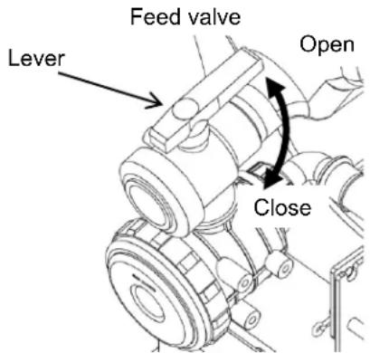
[4] Set the tractor engine to low speed and turn the PTO.
CAUTION - If the PTO is connected abruptly when the tractor engine is running at high speed, the spray pump may malfunction; accordingly, be sure to keep the engine speed low when turning the PTO.
[5] Operate the throttle and adjust the PTO speed to a range of 440 to 615 rpm.
[6] Turn the pressure adjustment dial to adjust the pressure to a desired level.
[7] Set the spray cock in the "Open" position and spray from the nozzle, and check the condition of spraying from each nozzle for abnormality. With a standard nozzle, the nozzle is spraying normally if the mist spreads in a fan shape. When the spray angle is extremely narrow or the mist thickness is uneven, remove the nozzle and check if contaminants, etc., are clogging the nozzle. If the nozzle is clogged, clean the nozzle and spray again to check.
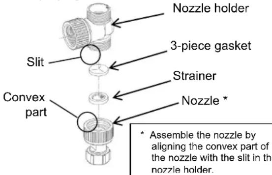
[8] When installing the nozzle, securely tighten the nozzle cap to prevent water from leaking.
Caution
● The nozzle plate will wear and the discharge amount will increase after long hours of use, in which case the nozzle plate should be replaced.
- When storing the machine over winter or for an extended period of time, also drain the nozzle.
12
Precautions for Spraying

Warning
● The person performing spraying should wear protective gears for agrichemical spraying (such as a protective mask, protective glasses, boots, rubber gloves and waterproof protective cloth, etc.) to prevent the reagent from coming in direct contact with the body.

CAUTION
- Keep only the required amount of spray agent in the reagent tank to prevent leftovers.
● Reagent spouts out from the nozzle. Do not let anyone come near the nozzle during spraying.
13
Reagent Preparation

Warning
- Carefully read the operation manual of the applicable reagent and use the reagent correctly.
[1] Prepare only the required amount using a dedicated container.
[2] In the case of water-dispersible powder, dilute a small amount with water in a bucket, etc., and put the prepared solution in the reagent tank. Put reagent after water.
[3] Confirm that the spray cock is in the "Close" position.
[4] Turn the PTO of the tractor at a speed in a range of 440 to 615 rpm.
[5] Turn the pressure adjustment dial to adjust the pressure to a desired level.
[6] Run the PTO several minutes in this condition to fully agitate the reagent.
[7] If spreading agent is used, follow the instruction manual that came with the spreading agent.
14
Spray Method
Caution
● Before spraying, adjust the hydraulic lever on the tractor until the universal joint becomes level. If the angle of the universal joint is too sharp, the spray pump may malfunction.
[1] Move the machine to the spray location.
[2] Stop the machine just before the position where you want to start spraying.
[3] Open the side booms. (Refer to page 16.)
[4] Confirm that the feed valve is open.
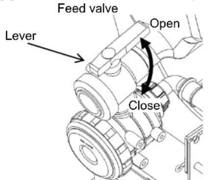
[5] Set the tractor engine to low speed and turn the PTO.
[6] Operate the throttle and adjust the PTO speed to a range of 440 to 615 rpm.
Caution
- If the PTO is connected abruptly when the tractor engine is running at high speed, the spray pump may malfunction; accordingly, be sure to keep the engine speed low when turning the PTO.
- Use the PTO of the tractor at speeds between 440 and 615 rpm. If the PTO speed is too high or too low, uneven spraying or spray pump malfunction may result.
[7] Turn the pressure adjustment dial to adjust the pressure to the required level.
[8] Put the shift lever on the tractor in the required position and start driving.
[9] After arriving at the desired starting position, set the spray cock in the "Open" position and start spraying.
Caution
- Do not run the spray pump continuously for 1 minute or more after reagent has run out. The spray pump may malfunction.
15
Stopping the Spraying
[1] When the spraying is done, set the spray cock in the "Close" position.
[2] Turn the pressure adjustment dial counterclockwise until it stops, to lower the pressure.
[3] Idle the tractor engine.
[4] Stop the PTO of the tractor.
[5] Close the side booms. (Refer to page 16.)
Caution
- If the work is stopped without returning the pressure adjustment dial to the 0 position, the spray pump may not suction reagent the next time it is used.
16
After Spraying
■ Cleaning the reagent tank
[1] If reagent remains in the reagent tank, put a container which receives remaining reagent under the water absorption strainer and then remove the cap on the water absorption strainer to collect the remaining agent. (Set a spray plan that will not cause reagent to remain.)
[2] Use clean water to flush the reagent tank thoroughly.
[3] Clean the water absorption strainer.
[4] Clean the water filter net in the reagent tank.
[5] Install the water absorption strainer again, and put around 50 liters of clean water in the reagent tank.
[6] Open the side booms and spray from the nozzle by following the spray procedure, to clean inside the piping and nozzle. Spray until all liquid is gone.
Caution
- Do not run the spray pump continuously for 1 minute or more after clean water has run out. The spray pump may malfunction.
■ Other tasks
[1] Thoroughly wash the machine using clean water.
[2] Return reagent to the storage cabinet and lock the cabinet.
[3] Make an entry on the agrichemical use journal.
[4] Clean the containers used.
[5] Clean the protective gears.
[6] Take off the clothes and wash your body from top to bottom.
[7] Lower the stand of the machine and store the machine with the stand contacting the ground.
17
Maintenance and Inspection
■ Inspect each part at the timing shown in the table below.

Caution
● Perform inspection/servicing with the boom sprayer installed on the tractor and also with the stand extended.
- Stop the tractor engine, lock the hydraulics and remove the key before performing maintenance/inspection.
- If any inspection or servicing item requires the tractor engine to remain running, do not perform such item on your own, but always contact the service personnel at your Maruyama dealer instead.
Dispose of oils, etc., properly.
Inspection Item List
| Inspection location | Inspection item | Inspection/replacement timing | Remarks |
| Mounting bolt/nut | Looseness | Before start of work | |
| Securely tighten. | Whenever looseness if found, or every year | ||
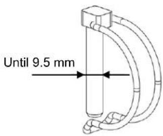
| Side boom | Worn shaft lock pin | Before start of work | Use limit: 9.5 mm |
| Spray pump | Crank caseCheck if oil is dirty or leaking and also check the oil level. | Before start of work | |
| Crank caseChange oil. | Every 100 hours (*1) | SAE#10W-30 SJ class or higher, 0.42 liter | |
| Add to the lubrication locations. | Every 100 hours | SAE#10W-30 SJ class or higher, 3 to 5 drops | |
| Rattling/loose input shaft | Before start of work | ||
| Add grease to the input shaft. | When the universal joint is installed | Chassis grease | |
| Water filter net | Clean. | Before start of work | |
| Water absorption strainer | Clean. | Before start of work | |
| Reagent piping connection parts | Looseness | Before start of work | |
| Securely tighten. | Whenever looseness if found | ||
| Nozzle | Clogging | Before start of work | |
| Replace | Replace every 100 hours (rough guide) | *2 | |
| Jet nozzle | Clogging | Before start of work | |
| Replace | Replace every 100 hours (rough guide) | *2 | |
| V-belt | Looseness and damage | Every 100 hours (*1) | |
| Winch | Frayed or rusty wire | Before start of work | |
| Brake effect | Before start of work | ||
| Center boom roller | Worn or cracked | Every 50 hours |
*1 --- Check after 50 hours only for the first time.
*2 --- Even before the replacement timing arrives, replacement may be required if any of the following symptoms is found:
• The pressure does not rise.
- Clogging occurs and persists after cleaning.
- The spray pattern is disturbed.
■ Mounting bolt/nut
Check the mounting bolts and nuts of the lower link pins, reagent tank, mast frame, spray pump, center boom and side booms for looseness.
Securely tighten any loose bolt/nut found.
Walk around the machine and also inspect other tightening points (bolts, nuts, etc.) for looseness.
Securely tighten any loose bolt/nut found. Also check the pins, etc., for rattling.
Side boom
Inspect the shaft lock pins for wear. Replace any severely worn pin with a new one. The use limit is 9.5 mm.
■ Spray pump

Caution
● Before draining oil, wait for it to cool.
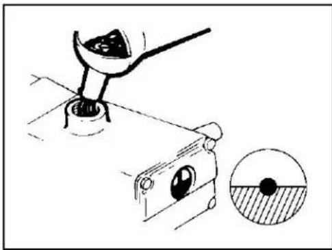
[1] Check if oil is filled to the red point on the oil gauge in the crank case of the spray pump, and also check if the oil is dirty. If the oil level is low, add oil. If the oil is dirty, change the oil. Add SAE#10W-30 by 0.42 liter. Change oil after 50 hours for the first time, and thereafter change oil every 100 hours. Oil degrades over time, so change oil at least once a year even before the aforementioned timing arrives.
natural_image
Technical illustration of a mechanical device with a lever and a close-up inset showing a circular feature (no text or symbols)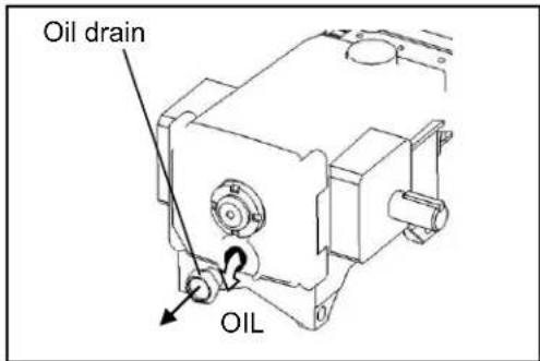
[1] Before commencing work, add around 3 to 5 drops of oil into the three holes (oil filler ports) on the crank case as shown in the figure. Add SAE#10W-30 SJ class or higher oil. (Every 100 hours)
Water filter net
Inspect the water filter net for attachment of dust or foreign objects, and clean the net if necessary.
■ Water absorption strainer
Inspect the water absorption strainer for attachment of dust or foreign objects, and clean the strainer if necessary.
■ Reagent piping connections
Perform spray inspection (refer to page 22) and inspect if water leaks from the connection part of each hose. If water is leaking, inspect the gasket and securely tighten the hose fitting.
Nozzle
Perform spray inspection (refer to page 22) and check the spray condition of each nozzle for abnormality, and replace the nozzle if any abnormality is found. As a rough guide, replace the nozzle every 100 hours.
Jet nozzle
Perform spray inspection (refer to page 22) and confirm that water jets out from the jet nozzle. If the water flow is weak, the nozzle may be clogged. Ask your Maruyama dealer to clean the jet nozzle. Replace the jet nozzle every 100 hours.
V-belt
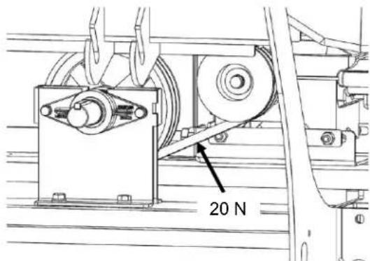
Adjust the belt tension so that when the center of the belt is held with 20 N (2 kg) of force, the belt deflects by approx. 2.5 mm.
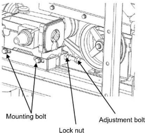
Adjust the tension by loosening the mounting bolts of the spray pump and tightening the adjustment bolt at the rear of the spray pump.
After the adjustment, lock the adjustment bolt with the lock nut and securely tighten the spray pump fixing bolts.
Winch
Visually inspect the wire for fraying and rust. Apply anti-rust oil on the wire periodically. (Refer to page 29.)
Also when raising/lowering the center boom, check if the center boom does not drop and remains at the current height even if the hand is released from the handle.
If the center boom drops when the hand is released from the handle, the winch may be faulty. Consult the Maruyama dealer near you.
Lubricant List
| Lubricating location | Applicable oil | Volume | Periodic change | |
| Spray pump, crank case | 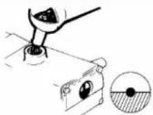 | SAE10W-30 SJ class or better | 0. 42 liter | Initial: 50 hours Subsequent: 100 hours (*1) |
| Base of spray pump cylinder | 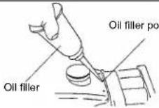 | SAE10W-30 SJ class or better | 3 to 5 drops | Every 100 hours (*2) |
| Input shaft | 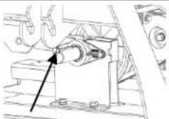 | Chassis grease | Appropriate amount | Once every year |
| Fulcrum of moving part | Chassis grease | Appropriate amount | Once every year | |
| Wire | Anti-rust oil | Appropriate amount | Once every year | |
*1: Change at least once a year even before an elapse of 100 hours.
*2: Add oil at least once a year even before an elapse of 100 hours.
19 Long-term Storage
If the machine is not used for a long period of time, follow the care procedure below:
[1] Perform the maintenance and inspection items.
[2] Service any problem locations found. Perform any service item after consulting with your Maruyama dealer.
[3] Spray by following the spray inspection procedure, to clean the piping and nozzle. When all liquid is gone, run the spray pump for 30 more seconds or so to drain the water.
[4] Set all spray cocks in the "Open" position.
[5] Thoroughly wash the machine using clean water.
[6] In areas where paint has peeled, remove the rust using sand paper, etc., and give a new coat of paint.
[7] Keep the lid of the reagent tank open for better ventilation. Also remove the water absorption strainer.
[8] Lower the stand until it contacts the ground, and remove the machine from the tractor. (Remove the machine by following the installation procedure in the reverse order.)
[9] Add grease/oil to the lubricating locations by referring to the lubricant list.
[10] Store the boom sprayer securely in a place free from humidity or dust.
20
Piping Diagram
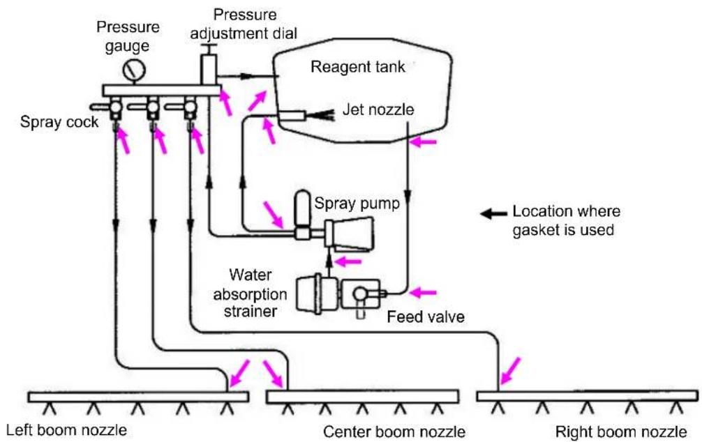
flowchart
graph TD
    A["Left boom nozzle"] --> B["Spray cock"]
    B --> C["Pressure gauge"]
    C --> D["Pressure adjustment dial"]
    D --> E["Reagent tank"]
    E --> F["Jet nozzle"]
    F --> G["Spray pump"]
    G --> H["Feed valve"]
    H --> I["Water absorption strainer"]
    I --> J["Center boom nozzle"]
    J --> K["Right boom nozzle"]
    style A fill:#f9f,stroke:#333
    style K fill:#f9f,stroke:#333
    note right of H Location where gasket is used
21
Troubleshooting

Caution
● Perform troubleshooting with the boom sprayer installed on the tractor and also with the stand extended.
- Stop the tractor engine, lock the hydraulics and remove the key.
- If any troubleshooting item requires the tractor engine to remain running, do not perform such item on your own, but always contact the service personnel at your Maruyama dealer instead.
| Phenomenon | Cause | Action |
| The boom sprayer cannot be installed on the tractor. | The boom sprayer was installed on inclined ground. | Install the boom sprayer on flat ground. |
| A pin is stuck on the tractor. | Remove the pin. | |
| The top link of the tractor is short. | Adjust and increase the length of the top link of the tractor. | |
| The nozzle does not spray. | There is no reagent. | Add the required amount of reagent. |
| The PTO is not turning. | Turn the PTO. | |
| The feed valve is closed. | Open the feed valve. | |
| The spray cock is in the "Close" position. | Set the spray cock in the "Open" position. | |
| The nozzle is clogged. | Clean the nozzle. | |
| The pulley is spinning. | Ask your Maruyama dealer to inspect the belt. | |
| The spray pressure does not rise. | The PTO speed is low. | Turn the PTO at a speed in a range of 440 to 615 rpm. |
| The pressure adjustment dial is not adjusted. | Turn and adjust the pressure adjustment dial. | |
| The water absorption strainer is clogged. | Clean the water absorption strainer. | |
| The spray pump/pressure adjustment valve has a worn part(s). | Ask your Maruyama dealer to perform repair. | |
| The nozzle is worn. | Replace it with a new nozzle. | |
| The jet nozzle is worn. | Replace it with a new jet nozzle. | |
| The pulley is spinning. | Ask your Maruyama dealer to inspect the belt. | |
| Abnormal agitation | The jet nozzle is worn or clogged. | Clean. |
22
List of Key Consumables
| Location of use | Item name | Part number | Quantity used |
| Spray pump | Seal gasket | 100015 | 3 |
| Piston gasket set | 116121 | 3 | |
| Cap of oil filler port | 117420 | 1 | |
| Felt gasket | 130515 | 3 | |
| Crank case lid o-ring | 014041 | 1 | |
| Oil seal | 117423 | 2 | |
| Oil seal drain o-ring | 023170 | 1 | |
| O-ring for pipe receiving fitting | 015862023172 | 93 | |
| Cylinder pipe | 022929 | 3 | |
| Water feed valve | 124277 | 3 | |
| Water feed valve stopper | 118628 | 3 | |
| Discharge valve assembly | 120276 | 3 | |
| Pressure adjustment valve | Valve rod for pressure adjustment valve | 016975 | 1 |
| Valve sack for pressure adjustment valve | 012256 | 1 | |
| Bellows gasket for pressure adjustment valve | 016972 | 1 | |
| Bellows for pressure adjustment valve | 011451 | 1 | |
| Pressure adjustment valve seat | 117443 | 1 | |
| Pressure adjustment valve ball | 107238 | 1 | |
| O-ring | 014179 | 1 | |
| Water absorption strainer | O-ring | 567292 | 1 |
| Nozzles | Kirinashi nozzle N-KA-8R | 188492 | 14 |
| 3-slotted gasket | 180147 | 14 | |
| Strainer | 107489 | 14 | |
| Jet nozzle | 198798 | 1 | |
| Drive part | V-belt | 292886 | 2 |
MEMO
MARUYAMA MFG. CO., INC.
P/N. *****-00February de 2016
- Introduction
- ■ Scope of Use
- ■ Precautions
- ■ Lending the Machine to a Third Party
- International Units
- Table of Contents
- 1
- For Safe Work
- Overview
- Precautions When Installing the Boom Sprayer on the Tractor
- Driving
- Clean water is sprayed for adjustment of spray pressure and spray check.
- Storage
- Chocking the Tires
- Main Specifications
- 4
- Handling of Warning Labels
- Warning
- Caution
- 5
- Preparing the Stand
- How to Assemble the Stand
- How to Install the Stand
- How to Use the Caster Lock
- 6
- Installing/Removing the Boom Sprayer on/from the Tractor
- How to Install the Universal Joint
- ■ Installing the Boom Sprayer on the 3-point Link Tractor
- Preparing the Tractor
- Installing the Boom Sprayer on the Tractor
- 7
- How to View/Use Each Unit
- ■ Reagent tank
- ■ Jet nozzle
- ■ Water absorption strainer/feed valve
- ■ Spray pump
- ■ Pressure adjustment dial
- ■ Spray cock
- ■ Mast frame
- ■ Boom device
- How to Open/Close the Side Boom
- How to Use the Winch and Adjust the Spray Height
- 8
- Spray Plan
- Supplement
- Startup Inspection
- How to Feed Water
- Spray Inspection
- 12
- Precautions for Spraying
- 13
- Reagent Preparation
- 14
- Spray Method
- 15
- Stopping the Spraying
- 16
- After Spraying
- ■ Cleaning the reagent tank
- ■ Other tasks
- 17
- Maintenance and Inspection
- ■ Mounting bolt/nut
- Side boom
- ● Before draining oil, wait for it to cool.
- Water filter net
- ■ Water absorption strainer
- ■ Reagent piping connections
- Nozzle
- Jet nozzle
- V-belt
- Winch
- Long-term Storage
- 20
- Piping Diagram
- 21
- Troubleshooting
- 22
- List of Key Consumables
- MEMO
- MARUYAMA MFG. CO., INC.
Brand : Maruyama
Model : BSM201
Category : Uncategorized