
DVR - Video recorder Elmo - Free user manual and instructions
Find the device manual for free DVR Elmo in PDF.


| Product Type | Digital Video Recorder (DVR) |
| Brand | Elmo |
| Model | X-Series DVR (v5.01) |
| Video Inputs | Up to 16 BNC connectors |
| Recording Modes | Continuous, Motion, Sensor, Pre-alarm, Combined |
| Video Compression | Proprietary with watermark (ELMO watermark) |
| Max Recording Resolution | 720x480 (NTSC) |
| Frame Rate | Configurable per camera, up to 30 fps total (depending on capture board) |
| PTZ Control | Yes, via RS422/485 and software (supports multiple PTZ protocols) |
| Audio Recording | Up to 8 channels (requires sound card and continuous recording) |
| Backup Options | CD/DVD, USB, network (encrypted, AVI, snapshot) |
| Remote Access | ELMO DVR Remote software and Websecurity |
| Network | Ethernet (RJ-45), supports LAN, PSTN, ISDN, leased line |
| Storage | Up to 4 internal hard drives (configurable) |
| Power Supply | Requires UPS (min 500W) for reliable operation |
| Video Format | NTSC only |
| Dimensions | Rack-mountable server unit (exact dimensions not specified) |
| Operating Temperature | 18°C - 25°C (64.4°F - 77°F) recommended |
| Warranty | 3 years parts, 1 year labor (HDD 1 year parts+labor) |
Frequently Asked Questions - DVR Elmo
User questions about DVR Elmo
0 question about this device. Answer the ones you know or ask your own.
Ask a new question about this device
Download the instructions for your Video recorder in PDF format for free! Find your manual DVR - Elmo and take your electronic device back in hand. On this page are published all the documents necessary for the use of your device. DVR by Elmo.
USER MANUAL DVR Elmo
ELMO DVR User Manual v5.01
ELMO DVR User Manual v5.01
Copyright ©2007 ELMO USA CORP.
All rights reserved. No part of this manual may be reproduced or transmitted in any form or by any means, electronic or mechanical, including photocopying, recording, or by any information storage or retrieval system, without the prior written permission of the copyright owner and the publisher.
Table of Contents
ELMO DVR Server 1
1. Introduction ...... 2
1.1. Welcome 2
1.2. Important changes to ELMO DVR, v.5.01 2
1.3. Limited Warranty 2
1.4. General 3
1.5. Precautions ...... 3
1.6. Unpacking 3
1.7. ELMO DVR Back View 4
2. Starting ELMO DVR Server 5
2.1. Logging In/Out 5
2.2.ELMO DVR Server Main Screen 6
2.3.PTZ mode 9
3. Configuring ELMO DVR Server 13
3.1.Hardware Setup - Camera Setup 13
3.2. Hardware Setup - Sensor Setup 14
3.3. Hardware Setup - Control Setup 16
3.4. Hardware Setup - External Monitor Setup 17
3.5. The Preset Touring & Alarm/Preset Setup 18
3.6.Motion Setup 19
3.7. Schedule Setup - Simple Mode 24
3.8. Schedule Setup - Advanced Mode 26
3.9. Screen Division 27
3.10.Communication Setup 28
3.11. Server Information 29
3.12. Password Setup 35
3.13. Audio Settings 38
3.14. System Setup 39
3.15.Storage Structure Setup 48
3.16.E-Map Setup 51
3.17.View Log Records 58
3.18. Email Setup 59
3.19. Intelli-Guard™ 62
3.20. Virtual Ruler 68
3.21. Intelli-Zone™ 71
3.22. Motion Tracking 73
3.23. VideoLogix™ Setup 74
3.24. Snapshot Setup 82
4. Search on ELMO DVR Server 86
4.1.Time Panel 87
4.2. Tools Panel 90
4.3. Video Recording Playback 91
4.4. Snapshot Function 91
4.5. Panorama Function 92
4.6. Image Zoom In/Zoom Out 93
4.7. Using Bookmark 94
4.8. Advanced Search Panel 94
4.9. Image Settings Panel 99
Backup on ELMO DVR Server 101
- Quick CD Backup 102
- Manual Backup 104
2.1. Snapshot Backup 104
2.2. Encrypted Backup 107
2.3. AVI Backup 110
2.4. Email Backup 113
- Multi-CD Backup 117
ELMO DVR Remote 118
- Starting ELMO DVR Remote 119
1.1. Logging In 119
1.2. Creating New Remote Site Connection 120
1.3.Main Screen 123
1.4. Connecting to the Remote Site 126
1.5. Viewing the cameras on the connected remote site 127
1.6. Using Multi-Site tool 128
1.7. Disconnecting from the Remote Site 129
- Configuring ELMO DVR Remote 130
2.1 About ELMO DVR Remote 130
2.2. Configuration Setup 130
2.3. Communication Setup 132
2.4. Other Setup 133
- Search on ELMO DVR Remote 134
3.1. Local Backup Search Categories 134
3.2. Local Search on ELMO DVR Remote 135
3.3. Search Window in the Local mode 135
3.4. Searching a Connected Remote Site 137
Backup on ELMO DVR Remote 139
- Automatic Backup 140
- Manual Backup 141
2.1. Snapshot Backup 141
2.2. Encrypted Backup 142
2.3. AVI Backup 143
PACDM™ Integration 147
- Setting up Text Overlay 148
ELMO DVR Server
1. Introduction
1.1. Welcome
Thank you for purchasing our ELMO X-Series Digital Video Recorder (DVR). ELMO is a registered CORP.
This manual will guide you through the usage of ELMO DVR Server and ELMO DVR Remote questions or concerns, please visit our website at http://www.elmousa.com or contact our technical
1.2. Important changes to ELMO DVR, v.5
Please note that the video recordings made with earlier versions of ELMO DVR Server will not DVR Server v.5.01. The ELMO DVR Server v.5.01 is only available with the hardware upgrade.
Notice that the systems supporting ELMO DVR Server v.5.01 do not have physical watchdog cat built-in within the system. The built-in watchdog function works the same way as the physical be turned ON/OFF with the switch or button (depending on the chassis model).
1.3. Limited Warranty
ELMO USA CORP. warrants this product to be in compliance with its own plans and specific defects in materials and workmanship under normal use and service for all parts, excluding the (or the equivalent) of three (3) years after the original purchase date. During this period, ELM( parts at no charge; however, labor costs will be charged after one (1) year.
Hard Drive: Parts + Labor = 1 year warranty
Other Parts: Parts + Labor = 1st year only*
Parts: 2nd and 3rd year only
* N.B.: Compact (CP) units are warranted for only one (1) year, parts
This warranty excludes costs for initial technical adjustments (setup) which are the responsibility of the dealer from whom you purchased the unit. It also excludes damages due to misuse or neglect. Damages resulting from electrostatic discharge (ESDI) will not be warranted. This warranty does not cover damages beyond ELMO USA CORP.'s shall ELMO USA CORP. be liable for any direct, indirect or consequential damages, loss of anticipated profits, loss of time or any other losses incurred by the buyer in connection with the purchase, installation, operation or failure of this product. We, ELMO and its agents, are not responsible for viruses. Users should install anti-virus software their own risk. For more details on the limitations of this warranty, contact your distributor.
**For technical assistance, please call: 1-877-877-7241
To obtain service, please follow these steps:
-
Arrange for delivery of your equipment to: ELMO USA CORP., 1478 Old Country Plainview, New York, 11803, USA.
-
All shipments should be shipped prepaid, insured and properly packaged (preferably in the origin) accompanied by a letter outlining the defect.
-
Supply your warranty registration, bill of sale, or other evidence of purchase date.
NOTE: The ELMO DVR must be used with an Uninterruptible Power St (rated at a minimum of 500 watts), with range protection. Failure to void all warranties!
1.4. General
This product is the product of ELMO USA CORP. advanced technology and has passed extensive ility tests. Copyright of this manual belongs to ELMO USA CORP., and may not be reprinted written permission. If you need to modify or repair your system, we recommend that you con Dealer/Installer. Otherwise, the system warranty will be voided. Should you have any problems or product, contact your local ELMO Dealer/Installer. This product is certified for domestic and industrial use: uTUVc certified for Europe, and UL certified for the USA.
1.5. Precautions
Please, do not install additional software on our system to be used as computer. Doing so will jeopardize the performance of the ELMO DVR Server and may even result in a system crash.
When selecting a storage location for the system, be sure to avoid:
• excessive heat, such as direct sunlight or heating appliances
• moisture, dust, and smoke
• magnetic fields or electrical waves
• temperatures below 5° Celsius or 41° Fahrenheit
• any obstructions to system ventilation holes
Before installing this system, always ensure the:
• power source is located within 3 feet or 1 meter of the UPS
• power is switched off ( ^** Do not plug the DVR unit in.)
• system and its connecting cables have sufficient space
• system is placed on an even surface
- system is situated far from electronic equipment such as microwaves, radios, fridge compressor wireless equipment such as a telephones or cell phones
- system is at room temperature (18° - 25° Celsius or 64.4° - 77° Fahrenheit)
1.6. Unpacking
To unpack the ELMO DVR, follow these steps:
- Place the box on a flat, clean surface.
- Remove the box by pulling and lifting the system up with both hands.
-
Place the system down carefully.
-
Read the User Manual thoroughly before installing the system.
- Make sure all the parts listed below have been included:

natural_image
Black industrial server unit with ventilation slots and a handle (no visible text or labels)Elmo DVR
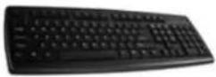
Keyboard
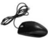
Mouse
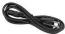
Power Cord

Communication cable
(Optional use for PAN/TILT /ZOOM camera)

Loop Out Cable and Fly Out Cable

Brackets appropriate to the chassis type and screws

Data Feeder
(Included only when PACDM ^™ is ordered)
1.7. ELMO DVR Back View
The following diagram displays the back of the ELMO DVR:

2. Starting ELMO DVR Server
The ELMO DVR Server is the professional intelligent and innovative software application that offers the user a variety of controls and settings that make the experience with ELMO DVR effortless and efficient.

Usually the ELMO DVR Server starts automatically; if it doesn't, click the ELMO Server icon on the Desktop.
With Windows 2000™ and Windows XP™, virtual keyboard can be used to enter keyboard icon located on the lower right-hand side of the main screen.
![On-Screen Keyboard File Keyboard Settings Help esc F1 F2 F3 F4 F5 F6 F7 F8 F9 F10 F11 F12 pcc nk bk * 1 2 3 4 5 6 7 8 9 0 - = bk.sp ins hm pus nk / * - tab q w e r t y u i o p [ ] \ del end pdr 7 8 9 + luck a s d f g h j k l : * ent shift z x c v b n m . . / shift ↑ 1 2 3 cld alt cld ← + → 0 . eni](/content/2026/05/941759/images/e0131bf5a56e9a88e9d98d2dec99e552b8fc1dcfe2446db9ba3e3f600d6589fb.jpg)
2.1. Logging In/Out
After installation, ELMO DVR automatically creates an administrative account (elmo). It is recommend password for this account or to create at least one other Master User account to set up a advisable to reserve the master user option for technicians only. Only the master users have a Desktop and can create other master users.
See Password Setup for more information.
In case if the username and/or password were lost, contact the local dealer for information or
To log into the ELMO DVR Server, do the following:
1.
Click
Login

- The Log In window will appear on the screen
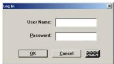
- If logging in for the first time, enter elmo for User Name and elmo for Password. Or log in with the name and password assigned by system administrator. Use the virtual keyboard if necessary.

- Click the OK or press Enter to continue
To log out of the ELMO DVR Server, do the following:
1.
Click
Logout
- The confirmation window will be displayed. Click OK to log out.

Related Topics: Password Setup
2.2. ELMO DVR Server Main Screen
Main Screen contains the following areas:
- About
- Help
- Server Location
- Server ID
- Date and Time
-
Login/Logout
-
Search
- Setup
- Panic
- PAC
- Storage/Hard Drive Meter
-
Camera panel
-
Sensor/Control panel
- Exit
- Snapshot Button
- Rotate Cameras
- Full Screen
- Screen Division Buttons

ELMO DVR Server Main Screen Features:
About
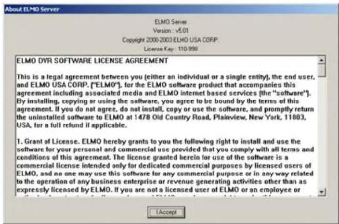
About - Displays the ELMO license agreement and the version of the ELMO installed. Click I Accept to close.
Help
Help - Displays the help menu window. The major help topics are available.
Location: Boston
Location - displays the customer name for Server location.
Server ID: 110-998
Server ID - displays the Server ID. This information is necessary to connec remotely.
2006/10/31 14:09:13
Date and Time - displays the current date and time. This information is Windows OS. If date/time is not correct, access the Desktop |Master users pre + Ctrl + F4) and double-click the Windows time display in the right-hand appropriate time, click Apply and restart the ELMO DVR.
Login/Logout - in order to access the ELMO DVR Server Setup, search or access PACDM™ the user must first log in.

Search - displays the ELMO DVR Server Search window, which permits came search, image editing and printing, file backup by time/date/camera, object search,

Setup - displays the ELMO DVR Server Setup menu
Panic – the Panic button acts as an Active Sensor Backup. When Panic is clicked or the sensor is activated the system will backup the 5 prior minutes of encrypted video activation length of recording is configured by the user in the System Setup

PAC - brings up PACDM™ software for generating reports and P.O.S. or Card searching.


Total Space (Storage/Hard Drive Meter) - Displays the total space the hard drive. Also displays the amount of remaining free hard drive space recording. When no empty space is remaining, ELMO DVR Server goes into the and the word "Recycling" is displayed on the Total Space meter.

Camera panel

Note
To exit the software without shutting master users should press Alt + Ctrl + Shift + F4.
Camera panel indicates the ELMO DVR recording activity. Highlighted camera numbers represent curr down, cameras. In the example below, cameras 1 and 2 are currently recording.

Sensor and Control panel

The Sensor/Control panel activates selected controls and displays sensor status. Selected controls and are highlighted on Sensor/Control panel. In the example above, Sensors 7-8 are triggered and Co Control acts as a relay and can be controlled by a user (turned on/off) from the Sensor/Cont onlyl. Sensor works as a switch and cannot be manually controlled from the main screen.
Screen Division
The Screen Division buttons allow for customization of the main screen appearance. When a spe chosen, the corresponding amount of cameras will be displayed on the main screen. Important: The first available
cameras will be displayed. E.g. If the ELMO DVR has 12 available cameras and the 9-cameras Cameras 1-9 will be displayed on the main screen in a 9-cameras screen division. Screen Divis customized in the Screen Division Setup to display the selected cameras instead of the first av 4-cameras Screen Division button can be customized to display Cameras 2, 8, 10 and 11 inste
The Screen Division buttons change on cursor-over and when clicked. The red Screen Division but activated

Displays the first 4 available cameras in a 4-cameras Screen division on Screen. Click again to display next 4 cameras Displays the first 6 available cameras in a 6-cameras Screen division on Screen Displays the first 9 available cameras in a 9-cameras Screen division on Screen Displays the first 10 available cameras in a 10-cameras Screen division Display Screen Displays the first 13 available cameras in 13-cameras Screen division on Display Screen Displays the first 16 available cameras in a 16-cameras Screen division Display Screen
Rotate Cameras - This button continuously rotates cameras in the division (4-cameras screen division) in a sequence (1-4, 5-8, 9-12, 13-16, 24, 25-28, 29-32 (if applicable)). To stop camera rotation, click the dc Division button or click Rotate Cameras again to deactivate it. Full Screen - This button displays a single camera or chosen screw without any menu bars (no interface shown). Right-click to exit the fu Snapshot - This button allows taking a snapshot of each connected Live mode. Ensure that the Display Snapshot Button checkbox is off in the Server Information setup tab and the Snapshot Setup tab figured. If the Snapshot Setup is not configured, the Snapshot button active.
Related Topics: Screen Division | Server Information | Password Setup | Snapshot Setup
2.3. PTZ mode
The remote control feature of the PTZ camera, controlled by a user through ELMO software, i advantages. Ensure that the PTZ function in the Hardware Setup menu is enabled and that the of PTZ camera is chosen from the list.
To access the PTZ mode, do the following:
- Locate a PTZ camera in the main ELMO DVR Server window
- Click on the image. The PTZ window will be displayed.
PTZ cameras can be controlled from:
- ELMO DVR Server (authorized users only)
-
ELMO DVR Remote (authorized users only)
-
ELMO Websecurity
In the PTZ window the user can:
- change the pan-tilt settings
- zoom in and out
- focus the image
- configure the presets and the preset touring
The PTZ window can be controlled with:
- The PTZ window buttons
- The Mouse in-cameo function. To do so, point towards the desired direction with the mouse left mouse button
- The Keyboard Num Pad arrow buttons 14 and 6 for Pan; 2 and 8 for Tilt; - and +
The main areas of the PTZ mode window are:
- About - Same as in the main screen
- Help - Same as in the main screen
- Server Location - Same as in the main screen
- Server ID - Same as in the main screen
- Date and Time - Same as in the main screen
- PTZ Camera Menu
- Pan/Tilt Speed
- Pan/Tilt Setup
- Focus
- Zoom
- Close - Exits the PTZ Mode
- Preset Touring
- Preset Setup
- Snapshot Button - Same as in the main screen
- Rotate Cameras - Same as in the main screen
- Full Screen - Same as in the main screen
- Screen Division - Same as in the main screen
![Let More About Help LAN: Boston Super IQ 110-299 PAN/TLT 1 2 3 4 Pax ELMO Units, Head Speed: 511 15:19:50 PTZ Mode Auto Pan Point 1 Point 2 AUX Pan/TLT Speed 7 8 Focus Zoom 10 C1[CAMERA81] Screen Divisions 17 16 15 14 13 Get Preset Power Source 11 Extra Pcs Mode](/content/2026/05/941759/images/2299f499b8d7ea07e00c2041c4b59251a89d309d773a1696cd590215ac876423.jpg)
PTZ Camera Menu - this area is specific to each PTZ camera. The OSI dome camera will be replaced by AUX (Auxiliary) button for other supported PTZ. This function allows changing the camera settings remotely through the software, adjusting settings manually on the mounted camera.
Pan/Tilt Speed - this is the speed of the camera response to the user Pan/Tilt speed for the PT camera to move faster. Increase or decrease Pan/Tilt the arrows.

Pan/Tilt Setup - adjust camera Pan-Tilt position by clicking the arrows up left and right for Pan.

Focus - Focus the image by clicking + and - signs
Zoom - Zoom the PTZ camera in and out by clicking + and - signs

Preset Touring - this setup allows for the configuration of the presets used. Touring function.

Preset Setup - this menu allows for the set up of up to each PTZ camera. A preset is the unique combination of Pan, T values for each camera that gets recorded and stored by the EL After the preset is programmed, only one button has to be click the camera in the specific direction and/or zoom in/out instantly.
configured in this menu are also used by Intelli-Zone™ and the function.
To configure the presets for a PTZ camera, do the following:
-
Enter the PTZ mode by clicking on the PTZ camera on the main screen.
-
Locate the Preset menu in the bottom of the screen:
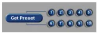
-
Click Get Preset. The button will become Set Preset
-
Program the desired Preset (see instructions below).
-
AFTER programming the preset, click the Preset number (1-10). The preset gets recorded once the preset number camera is clicked.
ameras

Note
PTZ function has to be enabled ID has to be assigned for all in Hardware Setup.
and PTZ

- Repeat Steps 4-5 to configure all presets.
- Exit PTZ mode
Program the desired Preset with the PTZ window buttons:
- Adjust camera Pan-Tilt position by clicking the arrows up and down for Tilt; left and right
- Increase/Decrease Pan/Tilt speed by clicking the arrows. The higher the speed, the faster the in response to the user command.
- Focus and Zoom in/out by clicking + and - signs
OR
Program the desired Preset with the in-cameo PTZ function:
- Point with a mouse cursor in the desired direction. An arrow will appear.
- Hold down the left mouse button, the camera will move in the desired direction.
- Focus and Zoom in/out with the Focus and Zoom buttons on the right side of the window.
OR
Program the desired Preset with keyboard:
Use Num Pad arrow buttons 14 and 6 for Pan; 2 and 8 for Tilt; - and + for Zoom
Related Topics: Camera Setup | Preset Touring | Intelli-Zone™
3. Configuring ELMO DVR Server
ELMO DVR Server Setup. Save and Close buttons.
Every ELMO DVR Server Setup page has Save and Close buttons:
The Setup tabs that require user input have a Virtual keyboard button:
Click Save before closing the Setup window or accessing a different Setup tab in order to save any changes made.
OR
Click Close to exit without saving.
When trying to change the Setup tab or close Setup without saving, a confirmation window v
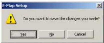
Click Yes to save the changes. Click No to exit without saving. Click Cancel to continue editing setup settings.
3.1. Hardware Setup - Camera Setup
3.1.1. Overview
Camera Setup allows:
- Assigning a numerical camera ID number to each selected camera
- Associating Sensor(s) with selected cameras
- Configuring selected cameras to record based on motion that occurred on associated camera(s)
- Choosing the PTZ camera type
- Setting up an auto pan for selected cameras
3.1.2. Creating/Modifying Camera Settings
Camera Setup
![Camera Setup Enable Cam. ID Name Sensor Motion P/T/Z Type [A/P] [Dwell] ✓ 1 0001 Front Door ✓ ELMO: Speed ✓ 30 ✓ 2 0002 Parking ✓ ELMO: Speed ✓ 30 ✓ 3 0003 Back Door ✓ ELMO: Speed ✓ 30 ✓ 4 0004 Warehouse ✓ ELMO: Speed ✓ 30 ✓ 5 0005 CAMERA05 ✓ ELMO: Speed ✓ 30 ✓ 6 0006 CAMERA06 ✓ ELMO: Speed ✓ 30 ✓ 7 0007 CAMERA07 ✓ ELMO: Speed ✓ 30 ✓ 8 0008 CAMERA08 ✓ ELMO: Speed ✓ 30](/content/2026/05/941759/images/87cb695f4d597f35cffd95385b443de8599335e11dbf50ddb2174f4c4e2219cb.jpg)
To setup all connected cameras, do the following:

Note
This feature is NOT available on Remote.

Note
The BNC connector number does to match the Cam. ID number.
-
Check the Enable checkbox for all connected cameras. The numbers correspond with the physical BNC connectors in the back of the DVR.
-
Assign a Camera ID to any camera that can be controlled by a user - a P/T camera. Cam IDs are assigned in order to distinguish between the different P/T cameras connected to the same parallel connection. M ELMO DVR their Cam ID assigned by dip-switches in the back of the camera. Fixed cameras do not
-
Label the cameras for easy identification (e.g. Front Door)
not have. Enter the Sensor number to be associated with the specific camera. If the specific sensor is triggered, that camera will begin recording (see Sensor Setup, Schedule Setup). In the above example, if Sensor 2 (Front Door) will start recording.
-
In the Motion field associate the current camera with one or more cameras. When motion is detected on an associated camera(s), the current camera will start recording. Motion detection has to be configured, has to be set to Motion recording for the associated cameras). (see Motion Setup, Schedule example, if the motion occurs on Camera 3 (Back Door), Camera 1 (Front Door) and 4 (W
-
Check the P/T/Z (Pan-Tilt-Zoom) checkbox for cameras supporting the P/T feature
-
Choose the correct camera make and model (Type) for the PTZ cameras from the list pro ELMO_DVR, which is the 200-400 (A/P) device. This function allows the PTZ camera to construct
-
Check the Auto-Pan (A/P) checkbox for the installed PTZ cameras. This feature allows the PTZ camera to return to the programmed auto pan after a user adjusts the PTZ settings remotely and exits the to the original settings.
-
Assign Dwell Time for the A/P setting. This is the time that will pass before the Auto-Pan (A/P) will be activated. In the above example, Camera 1 will return to the original pan after 20 seconds.
Related Topics: PTZ mode | Sensor Setup | External Monitor | Motion Detection | Schedule Setup | Screen Division | Password Setup
3.2. Hardware Setup - Sensor Setup
3.2.1. Overview
In the Sensor Setup the user can configure the connected sensors. Sensors are set as NC or NO = Normally Open).
An NC sensor is any sensor with an electrical circuit closed by default.
E.g. - a sensor on a closed door. When the door is opened, the electrical circuit is broken
An NO sensor is any sensor with electrical circuit open by default. E.g. - the light in a refrigerator. The light is off by default. When the refrigerator door is opened the circuit is closed and thus the sensor is triggered and the light goes on.
3.2.2. Creating/Modifying Sensor Settings

To configure the available sensors, do the following:
- Enable all connected sensors
- Choose NC or NO depending on the type of the sensor
- Choose which WAV file will play when the Sensor is triggered. Type in the WAV file na WAV files are stored in the C:\ELMO_Server\WAV folder.
- Choose Enable Alarm to have the chosen custom alarm sound every time the sensor is OR
Choose Disable Alarm to disable the custom alarm. The internal speaker alarm will sound instead.
- Set the Post Recording time between 1 and 60 s. In this example, the camera(s) will run Sensor is activated or after the detected motion stops.
To customize the Alarm for Sensor activation, do the following:

Note
Motion and Schedule Setups must figured.
be con- 1. Record the sound file in the WAV format
- Save the file in the C:\ELMO_Server\WAV folder
- In the Sensor Setup, type the WAV-source file name with the file extension in the Sound File field. In the above example, the customized WAV files are chosen for Sensors 1-5.

Related Topics: Camera Setup | Control Setup | Preset Touring | Schedule Setup | Communication Setup | Server Information | System Setup | E-Map Setup | Email Setup
3.3. Hardware Setup - Control Setup
3.3.1. Overview
Control settings are applicable only if controls are available and are being used.
Active Time
Active Time refers to the designated time when the control is active (is on). The default setting is 00:00-00:00, which means the control is always off. The control will be continuously on, if the Active Time is set to 00:00 - 24:00. During the Active Time, the control cannot be turned off from the main screen. Outside of the Active Time, the control can be activated by sensor, or manually from the main screen.
Dwell Time
Dwell Time is the time that the control will stay turned on when it is sensor-triggered. This does not apply if the control is turned on manually from the main screen. In other words, if the control is turned on m it will stay on until manually disabled by the user. Dwell time also does not apply during the Active Time, when the control is continuously on.
3.3.2. Creating or Modifying Control Settings

To configure the available controls, do the following:
-
Check the Enable checkbox for all installed controls
-
Give each control a descriptive Name.
-
Set the Active Time for each control if required. In the above example, Control 1 (Open the Door) is always off; Control 2 (Turn on the Light) is continuously on between 8:30 AM and 5 PM.
- Associate the controls with the desired Sensors. If a selected sensor is triggered outside of the Control Active Time, the specific control is activated. In the above example, if Sensor 1 is triggered, Cont be activated. If the Sensor 3 is triggered, Control 2 will be activated.
- Enter the Dwell (Sec) time for the control. In the above example, Control 1 (Open the Door) will stay on for 5 seconds if Sensor 1 is triggered. Control 2 (Turn on the Light) will stay on for 10 seconds outside of the Active Time.
Related Topics: Sensor Setup | Motion Detection | System Setup | E-Map Setup | Intelli-Guard™ | Intelli-Zone™ | VideoLogix™
3.4. Hardware Setup - External Monitor Se
3.4.1. Overview
The External Monitor section allows the user to view specified cameras on an external monitor. Cameras are displayed one-by-one in a sequence with a delay equal to the dwell time.
Dwell (Sec)
Dwell refers to the interval (in seconds) between the display of each camera.
3.4.2. Creating or Modifying External Monitor Setting

To set up an External Monitor do the following:
- Select the cameras to be shown in the sequence
- Specify the Dwell time for the sequence. (1-10 sec)
- Click Save
OR
- Check the Ext. Monitor Follows Main Screen checkbox to associate the external mode ELMO DVR Server main screen.
- Click Save
If the Ext. Monitor Follows Main Screen option is unchecked, the External monitor will display selected cameras one-by-one in the sequence. Each camera will be displayed for the length of the Dwe External Monitor setup. In this example, cameras 4, 9-12 will be shown in a sequence on the camera will be shown for 1 second.
If the Ext. Monitor Follows Main Screen option is checked, the configured camera sequence will be ignored. The External monitor will display the camera currently in full screen mode in the ELMO DVR or in response to detected motion. The external monitor will display the last camera until the in the Full Screen mode in the ELMO DVR Server.
Related Topics: Camera Setup
3.5. The Preset Touring & Alarm/Preset Se 3.5.1. Overview
The Preset Touring & Alarm/Preset Setup in the Hardware Setup tab is for PTZ camera setup. eras are configured in the PTZ mode. Preset Touring specifies the time that the PTZ cameras preset, and the Alarm/Preset Setup associates enabled sensors with configured presets for PTZ car specific Sensor is triggered, the assigned PTZ camera preset will be activated.
3.5.2. Configuring Preset Touring & Alarm / Preset
To set up the Preset Touring, do the following:
-
Program all desired presets in the PTZ mode
-
In PTZ mode, click on the drop-down menu under the Preset Touring button and check all the presets that will be used in the Preset Touring sequence. In the example below, Presets 1,3,4,5, and 8 Touring.
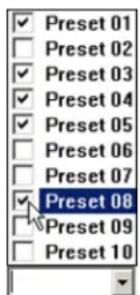
- In PTZ mode, click the Preset Touring button
- The Preset Touring will become Stop Touring. Click Stop Touring to stop camera touring.
-
Exit PTZ mode
-
In Hardware Setup, enter the Working Time value. This will configure the time that the PTZ camera will remain at each preset. In the example below, the PTZ camera will remain at each preset for 5

-
Click Alarm/Preset. The Alarm/Preset window will appear.
-
Configure the Preset for each camera related to the sensor number that will activate the below: Sensor 1 activates Preset 4 on Camera 1; Sensor 2 activates Preset 9 on Camera 1 on Camera 7; Sensor 5 activates Preset 5 on Camera 2.
![Alarm / Preset [ AL A R M S ] A - 01 A - 02 A - 03 A - 04 A - 05 A - 06 A - 07 A - 08 Camera 01 PRESET 04 -- -- -- -- -- -- -- -- -- - Camera 02 -- -- -- PRESET 05 -- -- -- -- -- -- -- - Camera 03 -- -- -- -- -- -- -- -- -- -- -- - Camera 04 -- -- -- -- -- -- -- -- -- -- - Camera 05 -- PRESET 09 -- -- -- -- -- -- -- - Camera 06 -- -- -- PRESET 01 -- -- -- -- PRESET 01 PRESET 02 Camera 07 -- -- -- -- -- -- --/PRESET 03 --/PRESET 04 Camera 08 -- -- -- -- -- --/PRESET 05 Camera 09 -- -- -- -- --/PRESET 06 Camera 10 -- -- -- --/PRESET 07 Camera 11 -- -- --/PRESET 08 Camera 12 -PRESET 09 PRESET 10 Save Close](/content/2026/05/941759/images/35396ba4f4096369f1da25cbb8560b7211d28cf496c357be45fefc77f0ff8d34.jpg)
Related Topics: PTZ Mode | Camera Setup | Sensor Setup
3.6. Motion Setup
3.6.1. Overview
Motion Setup allows for the configuration of up to 5 motion detection zones for each camera. options are configured in the Setup menu.

Note
Unless Motion Recording is activated in the Schedule setup, the camera will not record and motion will not be detected even if the Motion detection target zones are configured for this camera.

3.6.2. Setup for individual camera
![Sensitivity: Less More ✓ Alarm 00 H 00 M - 24 H 00 M ✓ Control 2 [Time] 0 H 0 M 5 S Area Clear Area Draw](/content/2026/05/941759/images/fbeb53aca1a3dc7c34296995b9131cac2c5682b6de5bc89a7341f9d6245f4435.jpg)
To set up each individual camera, do the following:
- Click the camera number. The chosen camera will be displayed in the live view screen.
- Set the camera's Sensitivity. The greater the Sensitivity, the less change in an image is needed to set off the alarm. If the Sensitivity is set to Less, the change in an image will have to be dramati function only works properly indoors. The natural changes in the outdoor environment (e.g. clo alarms.
- Check the Alarm checkbox to enable the internal speaker alarm for the Motion Detection
- Set the Active Time for the Alarm. If the motion is detected outside of the active time, the Alarm will not go off. In this example, the Alarm is always active.
- Check the Control checkbox to enable the control association for the chosen camera
-
Choose the control number to be associated with the Motion detection on the chosen came the Control 2 will be activated if any motion is detected on the selected camera.
-
Set the dwell [Time] for the control feature. This is the length of time that the control will stay on if activated by Motion detection. In the example above, the control will stay on for 5 seconds.
To draw the Motion detection zones on the selected camera, do the foll
- Place the cursor at the starting point on the live view screen
- Hold down the left mouse button and drag to draw a rectangular area. Up to 5 motion figured.
- Adjust the area if necessary
- Click Area Clear to reset all motion detection zones on a specified camera
- Click Area Draw to set the entire camera screen for motion detection
3.6.3. Individual Camera Adjustment

- Set the Brightness, Hue and Contrast for the selected camera
- Choose between Color and Monochrome recording. Color recording provides the realistic video images. Monochrome is best suited for low light conditions, such as nighttime recording.
- Click Default to reset the Brightness, Hue and Contrast values back to 0
3.6.4. Setup For All Cameras

To set the motion detection zones for all cameras, do the following:
- Click Area Draw to select entire screen on all cameras for motion detection
- Click Area Clear to clear all selected zones on all cameras. This will disable motion detection.

3.6.5. Setup For All Cameras - Recording/Display Op
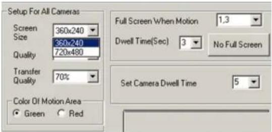
To set up recording/display options for all cameras, do the following:
- Choose the Screen Size for all cameras from 360x240 and 720x480 pixel. Screen Size refers to the resolution of the received video image. The larger the screen size, the larger the picture or Large screen size, however, will result in larger file size and shorter recording period.
- Choose Quality (30%-100%). This value refers to the recording quality of the video. The higher the percentage, the better the recording quality.
- Choose Transfer Quality (30%-100%). This value refers to the transfer quality of the video recording that is viewed remotely through ELMO DVR Remote. The lower the quality, the worse the image app speed, however, improves as the quality decreases.
- Choose Color of Motion Area between Green and Red depending on personal esthetical preferences. When the motion is detected on a specific camera, the triggered motion detection zone will be h screen in the chosen color.
- Set the cameras to be displayed in the Full Screen mode on the main screen, when mo cameras can be configured. Separate camera numbers with commas. In this example cameras 1 in the Full Screen mode if the motion is detected on them.
- Set the Dwell Time(Sec) (1 to 60 seconds) for the camera to stay in the full screen mode after the motion detection. In the example above, the camera will remain in the Full Screen mode for 5 s tection.
- Click No Full Screen to reset the Full Screen When Motion option
- Set Camera Dwell Time (3 to 30 seconds). This is the Dwell time for the camera rotation on the main screen. When the main screen is set to 4 cameras division and Rotate is clicked, available cameras will rotate according to the dwell time specified. In this example, the quad screen will display next 4

Note
This option only becomes available when 8 or more cameras are supported by the system.
3.6.6. Recording Frame Rate per Camera

Adjust the frame rate value individually for each camera. The sum of fps for all cameras is by the capture board.
In this example, it is known that the ELMO DVR has 12016 connected cameras. The total fps.
Increase the fps number for the cameras facing most important locations or locations, where most activity occurs. Increasing the fps on specific cameras will decrease the fps number on the rest of the cameras in or number.
Click Default to assign the common denominator fps for all enabled cameras. (E.g. If ELMO DVR has 120xx series capture board installed, and 12 connected cameras, 10 fps value will be assigned to each cam abled/unavailable cameras will automatically be assigned fps of 0.

Note
If the VideoLogix™ is enabled for a specific camera, the maximum frame rate is 13 fps.
3.6.7. Recording Frame Rate per Camera - Advance Setup

In the Advanced Setup:
- Configure the Record Frame FPS for each camera
- Configure the Emergency Frame FPS for each camera. The Emergency Frame Rate is activated when motion is detected on the specific camera. This function will reduce the recording speed on all other. The camera will return to its normal recording speed once the motion has stopped. In this speed is 10 fps for all 12 connected cameras. When the motion is detected, the camera, I will start recording 30 fps.
- Configure the Resolution for each camera
- Configure the Recording Quality for each camera
- Configure the Transfer Quality for each camera
- Click Reset to reset all changes. Click Ok to save the changes.
Related Topics: Camera Setup | Control Setup | Schedule Setup
3.7. Schedule Setup - Simple Mode
3.7.1. Overview
Schedule setup controls the type of recording for each camera: Continuous, Motion, Sensor or P can have its own settings, which can also be copied to other cameras.
C: Continuous recording – the video signal is being recorded continuously. A lot of hard drive space is required for this type of recording. Continuous recording is required for audio recording. Continuous recordir its own and cannot be combined with any other types of recording.
M: Motion recording – the selected camera records only when motion is detected. Motion detection target zones have to be configured in the Motion Setup. Motion recording can be used on its own or c and/or Pre-alarm recordings.
O/S: Object/Sensor recording – the selected camera records based on the alarms triggered in the VideoLogix or when the sensor has been triggered. The VideoLogix has to be enabled for the selected c be enabled and be associated with the specific camera in Hardware Setup. Object/Sensor recording own or can be combined with Pre-alarm recordings. When combined with M:Motion, O/S:Object/Sensor recording.

Motion and Sensor recording combined with Prealarm

P: Prealarm recording – is combined with either Motion, Motion and Sensor, or Object/Sensor recording. ELMO DVR stores 5 seconds of video recording in a buffer which is continuously overwritten. If Prealarm recording is used, a 5-second video buffer is added to the beginning of the recorded video segment.

3.7.2. Creating a quick recording schedule
- Select a Camera number
- Select the time for video recording. Click on the schedule, hold down the left mouse button and drag it until the desired area is selected
- Select the record mode: Continuous; Motion; Object/Sensor; Motion and Prealarm; Object/Sensor & Motion, Sensor and Prealarm.
3.7.3. Creating a custom holiday

Note
The holiday schedule will be identical Sunday schedule.
- Click Custom Configuration
- the Choose the date from the calendar
- In the Rotate drop-down menu, choose rotation setting: None, Month or Year
- Click Add. The date will be added to the Holiday List on the right.

3.7.4. Copying a schedule to other cameras

- Click Copy To and choose a desired cameras from the list
- Click All Cameras to apply the same schedule to all available cameras
3.8. Schedule Setup - Advanced Mode
To switch to the Advanced Mode, click Simple Mode and choose Advanced Mode.

In Advanced Mode, the time can be adjusted up to the minute:
| Camera 1 | Weekday | Saturday | Sunday/Custom | ||
| 00:00-00:24 | 00:00-01:00 | M:S:P | 00:00-01:00 | M:S:P | |
| 00:24-02:00 | M:S:P | 01:00-02:00 | M:S:P | 01:00-02:00 | M:S:P |
| 02:00-03:00 | M:S:P | 02:00-03:00 | M:S:P | 02:00-03:00 | M:S:P |
| 03:00-04:00 | M:S:P | 03:00-04:00 | M:S:P | 03:00-04:00 | M:S:P |
Example
The recording for Camera 1 based on the snapshot below is as follows:
| Camera 1 | Weekday | Saturday | Sunday/Custom | ||
| 00:00-01:00 | 0:S:P | 00:00-01:00 | M:S:P | 00:00-01:00 | C |
| 01:00-02:00 | 0:S:P | 01:00-02:00 | M:S:P | 01:00-02:00 | C |
| 02:00-03:00 | 0:S:P | 02:00-03:00 | C | 02:00-03:00 | C |
| 03:00-04:00 | 0:S:P | 03:00-04:00 | C | 03:00-04:00 | None |
| 04:00-05:00 | 0:S:P | 04:00-05:00 | C | 04:00-05:00 | C |
- Weekdays (12:00AM - 4:59AM) - based on Object/Sensor and Prealarm
- Saturdays (12:00AM - 1:59AM) - based on Motion, Sensor and Prealarm
- Saturdays (2:00AM - 4:59AM) - continuous recording
- Sundays and custom holidays (12:00AM - 2:59AM) - continuous recording
- Sundays and custom holidays (4:00AM - 4:59AM) - continuous recording
Notice that there is NO recording on Sundays and custom holidays 3:00AM-3:59AM. It is highly recommended not to leave any gaps in the video-recording schedule.
Related Topics: Camera Setup | Sensor Setup | Motion Setup | VideoLogix™
3.9. Screen Division
In the Screen Division setup, the main screen display is configured. Each screen division can be
To configure the screen division setup, do the following:
- Click the desired screen division icon
- In the Camera Selection menu, choose all cameras that will be displayed on the selected screen division. The cameras can be chosen sequentially or randomly.
- In the Large Screen drop-down menus, choose which camera(s) will be displayed in the large screen(s). This only applies to 6, 10, 13, and 33 screen divisions
Important: When switching to the larger screen division (e.g. from 4 to 16) click Default All, otherwise only 4 cameras will be displayed in the 16-cameras screen division.

Related Topics: Main Screen
3.10. Communication Setup
3.10.1. Overview
Communication Setup contains the Phone numbers and IP addresses that will be used in case numbers from Communication Setup are used by Intelli-Guard™. The IP Emergency Address is used the Emergency Monitor installed on the remote system.

3.10.2. Configuring Communication Setup
To set up Communication setup, do the following:
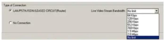
- Specify whether the connection is allowed. PSTN (Public Switched Telephone Network - modem). ISDN (Integrated Services Digital Network). If no connection available (no modem, no LAN, etc.), check No Connection - this will also prevent unwanted guests from accessing the system remotely.
-
Configure the Live Video Stream Bandwidth. This menu controls the bandwidth of the data transferred over the network. Select No limit to use all the available connection speed to transfer data. If No limit is selected, the Server might be slowed down in cases where multiple users are dialing into the
-
Define the Frequency of Call Out in a 24-hour period. If motion is detected or a sensor is triggered, the ELMO DVR will send an alert either to the phone number or to the IP address. The Frimum allowed number of phone call alerts per day. In the example below, the ELMO DVR 24 hours. If the sensor is triggered more than once in 24 hours, one phone call will be currencies will be ignored. The maximum number of phone call alerts that can be send per number does not limit the maximum number of alerts sent to the IP address (Remote Mor

- In the Emergency Setup, define which cameras/sensors will cause an alert. In this example, if the motion is detected on Cameras 1,3 and 7 or if the Sensors 2-4 are triggered, an alert will be se

-
Choose Emergency Phone Numbers to receive an alert via telephone. The first number is the default number for all emergency communications. The second number is a backup number in case 1 numbers are also used by the Intelli-Guard™ for Auto Dial-Out.
-
Choose an Emergency IP Address to receive an alert on the Emergency Monitor software installed on the same or another system.

- Set Transfer Time. Transfer Time specifies the time in seconds between the detected motion (triggered sensor) and the alert transmission. In the example above, the alarm will be sent to the Emergency after the sensor has been triggered.
Related Topics: Sensor Setup | Motion Setup | Intelli-Guard™ | VideoLogix™
3.11. Server Information
3.11.1. Overview
The Server Information tab permits configuring the Server, as well as obtaining information about DVR, and the exporting/importing settings. Setting the system time is also done on this tab.

3.11.2. Configuring Server Information Setup
The Server ID is a user chosen security code, to be entered when connecting remotely through ELMO DVR Remote or Websecurity. The Server ID can consist of up to 7 alphanumeric characters. When trying to a remote location, the system will check the Server ID, user Name and Password together. If incorrect, connection will fail.
In Server Information enter the following:

- Server ID (7 alphanumeric characters - digits/letters)
- Server Name
-
Location
-
Model
- Distributor
- Sale Date
- Any other notes
3.11.3. Configuring Main Screen appearance
Configure Main Screen appearance:

Display Server Information:
When checked, Server Location and Server ID will be displayed on top of the main screen. from the Server Information tab.

Display Camera Status Bar:
When checked, the camera status bar is displayed on the main screen.
Display Control Status Bar:
When checked, the control status bar is displayed on the main screen.
Display Sensor Status Bar:
When checked, the sensor status bar is displayed on the main screen.
Display Motion Detection Grid:
If checked, the motion detection grid will be displayed on the main screen when motion is 0 be displayed in either green or red, depending on the user settings in the Motion Setup and will highlight the area selected for Motion Detection Itarget zonel.
Check/uncheck to save image as JPEG/BMP
When unchecked, the snapshots are saved in BMP format by default. When checked, the snapshot format.
Disable Video on Main Screen:
When checked, the video from the main screen will be hidden when a user is logged in. 1 black, when this option is checked.
Display Snapshot Button
When checked, the Snapshot button is displayed on the Main Screen

to the Rotate t
3.11.4. ELMO DVR Information
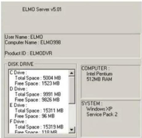
This part of the menu contains the following information about the ELMC
- the ELMO DVR Server version currently in use. Another way to find out which software version is in use, click About on the main screen.
- User Name (Windows user ID)
- Computer Name
- Product ID
- Processor type
- RAM size
- Windows operating system version
- Server Pack version
• List of drives/partitions
• Total and free space information
3.11.5. Additional Configurations

Enable Intelli Search Tooltip:
When checked, tooltips will be shown automatically when the cursor is pointed at the icon in

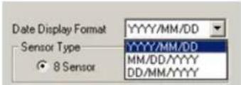
Date Display Format:
Permits changing the format of date and time display. Select the desired type of display.
Sensor Type:

Select 8 Sensor to use eight sensors and controls, and 16 Sensor to use sixteen sensors and controls. Proper number of sensor and control buttons will be displayed on the main screen, in Hardware and Communication Setup tabs.
All user settings can be exported to a folder of choice for future use. In case of multiple servers, the same settings can be easily applied by importing them from the folder.
Export Setting:
Will export customized Server settings to a folder for future use.
Import Setting:
Will import customized Server settings from the folder.
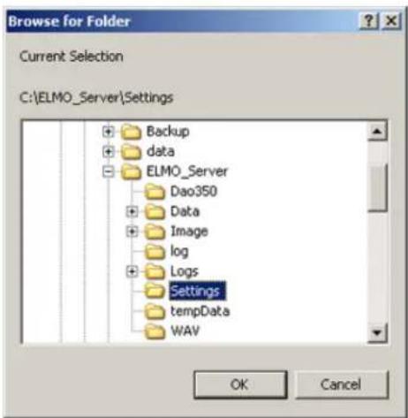
All exported Server settings are stored in a chosen designated folder. To store several sets of folders and export each set of settings to its designated folder. When exporting or importing is the hard drive and locate the appropriate folder for the exportation/importation of the Server settings and click OK.
3.11.7. Setting the System Clock
Adjust the System Clock if the system was shipped from a different time zone.
Get Time:
Imports the time from the Windows operating system.
Set Time:
The clock can only be set forward, not backwards. To set the clock back, exit the software Windows operating system. If the time is set forward in the Server, it will automatically be applied to the Windows system time.
If the time change has been successful, the following window will appear:

If an attempt was made to set the time backwards, the following warning window will appea

3.11.8. Switching to the Daylight Saving Time
Setting the time forward one hour will cause no system confusion. The particular hour jumped from the timeline. However, a problem may occur when the time is moved back one hour in the system will have to overwrite the previously recorded hour of information. As a result, valuable information could be lost, which is why the System time can only be set forward from the ELMO DVR Server. version has a newly developed, efficient way of avoiding this problem.
When servicing the older ELMO DVR Server versions (version E and older), a technician must r Saving Time on the machine and then reboot the system. In the new ELMO DVR Server ver hour is added when the Daylight Saving Time ends in the Fall and clocks are set back an adjustment prevents the loss of video data and does not "confuse" the system.
Example: With the new method, the timeline has two '1:00's. In this way the video data will not be lost or recorded over, and the system time stays correct and up-to-date.

Related Topics: Main Screen | Search Window
3.12. Password Setup
3.12.1. Overview
In Password Setup, the administrator can create, delete and configure other users' accounts.
After installation, ELMO DVR automatically creates an administrative account (elmo). It is recommend password for this account or to create at least one other Master User account to set up a advisable to reserve the master user option for technicians only. Only the master users have access to the ELMO DVR Desktop and can create other master users.
The master user accounts do not expire. For all other accounts Expiry Date and Daily Active Time can be configured. PTZ Priority can be configured for all user accounts.
Selected cameras, ELMO DVR Server functions and Setup tabs can be disabled in individual users' accounts in the Password Setup. The Password Setup allows the manager/administrator to restrict certain users from accessing important settings that should not be changed by non-authorized users. The administrator can choose setup tabs, such as Hardware Setup, Passwords Setup and Storage Setup tabs or "hide" specific cameras from the users.
When the Setup tab (camera) is disabled in the Password Setup, it will not show up in the screen! when they log in with their user name and password.

Note
Non-master users can still edit/delete their own and other non-master users' accounts. It is advisable to restrict non-master users from accessing the Passwords Setup tab.

3.12.2. Setup List
The Setup List has the list of all ELMO DVR Server setup tabs, main screen and other fun the individual users:
![Setup List ✓ PAC ✓ Enable MainScreen Function ✓ Exit ✓ Search ✓ Enable PTZ ✓ In-cameo PTZ ✓ Disconnect Remote Client[s] ✓ Panic Button](/content/2026/05/941759/images/1336bcdc30847a9a322942767c4ca4bdfbef2d7c6176a0599e6e3a187c5da305.jpg)
- PAC - When unchecked, hides the PAC button from the main screen. This option will not be displayed if the SPK key is not plugged in.
- Enable MainScreen Function - If unchecked, this option will disable the following main screen functions: Control panel, Screen Division buttons, About and Help buttons
- Exit - When unchecked, disables the Power button
- Search - When unchecked, hides the Search button from the main screen
- Enable PTZ - When unchecked, the PTZ cameras will not respond to the user command
- In-cameo PTZ - When unchecked, disables the mouse PTZ control in PTZ mode
- Disconnect Remote Client(s) - When unchecked, the user will not be unable to access the Setup menu, if someone dials into the ELMO DVR Server remotely I through ELMO DVR Remote or Websec all remote clients will be disconnected and the user will have access to the ELMO DVR S
ELMO DVR Remote warning messageELI


- Panic Button - When unchecked, hides the Panic button from the main screen
3.12.3. Creating new users

- Click Add User
master 2. Enter User Name and Password. Confirm Password.
-
Check the Master User checkbox to create a master user account.
-
For non-master users select Never Expires or configure the Expiry Date (default 3 months) and Daily Active Time. In the example below, the user's account will expire on December 31st, 2007. The user can log in daily from 8:00AM to 5:00PM.
The user will get the following message when trying to log in before the Start Date / past the Expiry Date or outside of the Daily Active Time.

-
Enable the Setup features and Setup tabs that the new user will have access to in the
-
Enable all the cameras that the new user will have access to in the Enable Camera list
-
Configure the PTZ Priority (1-30). The lower the number, the higher the priority. By default, the master users are assigned the PTZ Priority of '1', and the non-master users - the priority of '30'. The PTZ Priority setting is used to determine the user priority, when two or more users are trying to control the P
-
Click Save. The new user will appear on the list.

3.12.4. Deleting existing users
To delete an existing user, do the following:
- Click the user account to select it
- Click Delete
- Click Save
3.13. Audio Settings
3.13.1. Overview
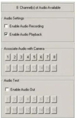
Audio recording is available with your ELMO DVR if a sound card is installed. Audio Setup d channels supported by the system. In case the system does not have a sound card installed, been detected, the message "Audio Recording Disabled" will be displayed.

Note
Continuous video recording is required for Audio Recording.
3.13.2. Configuring Audio Setup
To enable audio recording on specific cameras, do the following:
- Select the camera in the Associate Audio with Camera menu
- Check the Enable Audio Recording checkbox
To enable audio playback on specific cameras, do the following:
- Select the camera in the Associate Audio with Camera menu
- Check the Enable Audio Playback checkbox
To test the audio channel, do the following:
- Select the camera in the Audio out test menu
- Check the Enable Audio Out checkbox. The incoming audio signal will be sent to the system speakers
Related Topics : Schedule Setup

Note
This function is only available for the cameras that have Audio Recording enabled. When the video recording from these cameras is played back in the Search mode, the audio recording is played back together with video.
3.14. System Setup
3.14.1. Overview
In the System Setup tab, the user can:
- Configure server restart time
- Enable watermarking features
3. Configure backup schedules
![System Setup System Restart Time Enable Daily Every 1 week(s) Weekly Time 23:00:00 Monthly Sunday Thursday Monday Friday Tuesday Saturday Wednesday Synchronize System Clock with NTP Server Enable [Daily Synchronize Time] 02:00:00 Watermark Display WATERMARK logo Embed Text Overlay Backup Backup Settings Activate Sensor Backup Network Port Setting Select Num of Days to Store Data 1 day(s) The number of days you can select depends on your hard drive capacity Video Loss Alarm Enable Alarm Enable Sound Enable Control No. 5 [Working Time ] 0 0 30 Video Format NTSC SAVE CLOSE](/content/2026/05/941759/images/6a5725c8475ee77f7f1bf4265409efb5b1a377f6ad5344578f64e52e947a7672.jpg)
3.14.2. Configure System Restart Time
Enable the system restart time and set the system to restart once a week. Choose the most convenient time for the customer. If the system freezes it will be restarted by the I/O board. If, however the system is running smoothly without freezing, it can work for months without being restarted. The caches that will accumulate in t eventually slow the system down. To avoid this problem, it is advisable to set the weekly n
ELMO DVR
3.14.3. Synchronize System Clock with NTP Server
This feature allows synchronizing the DVR system clock with one of the default NTP servers d defined time. This function allows keeping the system time up-to-date without having to log out and updating the system time via Windows OS.
To use this feature, check off Enable checkbox.
Configure the Daily Synchronize Time (24 hour clock). The system time will be synchronize daily based on the time configured. The process may take several minutes. During the synchronization process, the fo be displayed.
Synchronizing system clock with NTP server... Please wait.
In addition to updating the system time, the synchronisation feature also checks the SPK key SPK key has been removed from the system, the PACDM application will stop working after t to "missing" by synchronisation feature.
3.14.4. Watermarking
Please note that the video recordings and snapshots made with ELMO DVR Server are always watermarked, regardless of the user configuration of this menu.
In the Watermark menu select one of the following (only one checkbox can be checked at the same time):

Display WATERMARK logo - If checked, the watermark logo will be displayed during the playback in the top right corner. Uncheck to hide the logo. Note that even if the watermark logo is hidden, the
Embed Text Overlay - If checked, the text "ELMO" will be embedded in the right bottom corner of every video frame. After the overlay text is embedded, it becomes a part of the video recording and car record without the embedded text.
3.14.5. More about Watermarking
When performing a snapshot backup from the Search mode, the option of saving the WaterMarl hard drive is available. Click Yes if this program has not been previously saved on a hard drive. If it has, there is no need to include it again. The Wmchecker.exe file will be added to the same folder as the saved snapshot.

3.14.6. Checking Authenticity of a Watermarked Ima
To check the snapshot authenticity with the WaterMark checker, do the
- Locate the folder, where the snapshot was saved.
2.
Locate the WaterMark Checker Program: Wmchecker.exe
-
Double-click to open the program.
-
Click File Open and choose the saved watermarked snapshot. The snapshot will be either in *.bmp or *.jpeg format, depending on the customer settings in the Server Information Setup tab.
-
Click Water Mark Check
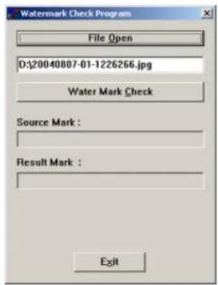
- If an image is intact and has not been edited/altered or tampered with, the Watermark will be recognized and approved.

- If an image was edited/altered or tampered with, the program will report the corrupted Wa

3.14.7. Creating Scheduled Backup
In the Backup menu:

Backup Settings: Set schedule for local or remote backups
Activate Sensor Backup: Configure the recording settings for the main screen's Panic button feature. Associate the backup with the specified Sensor(s). If a Sensor is triggered, or Panic is clicked, an encrypted video backup will be performed onto a CD-R/DVD-R.

Note
Make sure the CD-R/DVD-R is in the R/DVD-ROM drive. Please avoid using CD-R/DVD-RW as the lengthy formatting process might slow down the ELMD DVR.
The Scheduled backup is the scheduled encrypted backup. The Scheduled backup can be performed Remote drives. A number of media can be chosen for the same scheduled backup process.
To create a scheduled backup, do the following:
- Click Backup Settings

-
Click Add
-
In the Add Schedule window, name the backup schedule
-
Set the Start and End time of the scheduled backup recording
-
In the Rotate Option drop-down menu, choose from: None, Weekly, Monthly or Yearly
-
In the Backup Start Time Interval After drop-down menu, choose from: Immediately, 1, 2, 3 or 4 hours.
-
Click Add Media to choose backup destination. More than one medium can be added to the list. Video can be saved to the Local or Remote Drive.
Saving to the local drive.

a. Select Local Drive to save an encrypted video recording to any local drive
b. Click the drop-down menu in the Path field
c. Select the desired drive. The recording will be saved to the LocalDrive:\kdb\backup
d. Click Ok
Saving to the remote drive.

Note
All video recordings saved to the remote drive will be displayed under the Backup Data category in the ELMO DVR Remote local Search mode.

a. Select Remote Drive to save an encrypted video recording to a remote drive
b. Enter the IP Address of the remote computer
c. Enter the password to access the remote computer
d. Click Select Drive. The Drive Select window will appear.

Note
The ELMO DVR Remote Software has to be installed and the K-Remote Backup Server has to be running on the remote computer, otherwise the connection will not be established.

e. Choose the remote drive from the Drive Path drop-down menu once the connection has been established.
The recording will be saved to the RemoteDrive:\kdb\backup
f. Click OK
g. Click OK in the Select Backup Media window to close its
- Check the Overwrite Mode checkbox if the target medium is full. The video recording will be recorded over the old data. If this option is unchecked, no backup will be made on the full medium.
- Choose the Priority of the backup video recording between High and Low priority.
There are two types of video backup: current backup and scheduled (manual) backup. If "High" priority is assigned to the scheduled backup, the current backup will be automatically assigned "Low" priority. In practice, this priority affects the speed of the process, where "High" priority results in means fast backup and "Low" results in slow backup.
-
Click Add. The new schedule will be added to the list.
-
Click on the calendar to see the scheduled backups for each day.

To delete a schedule, do the following
-
Select the schedule from the list (left-click with the mouse)
-
Click Delete

3.14.8. Panic and Sensor Backup

ELMO

To associate the backup with a specific sensor(s), do the following:
-
Click Activate Sensor Backup
-
Choose post-activation recording time from drop-down menu (0-30 minutes)
- Select desired sensors to trigger the automated backup
- Click Save
- Click Close to return to Setup
By default, the Panic button feature backs up 5 minutes of video recording prior to the sensor/Panic button activation. The user, however, can configure the length of time that ELMO DVR will record after the sensor/Panic button activation.
Important: this option is not the same as pre-alarm, which uses a 5-second buffer and adds it to the final recording. The Panic button does not add any buffer video recording to the final backup. Instead it backs up only the recorded information that was recorded by ELMO DVR based on the Schedule Setup configurations (e.g.
The manual backup can be associated with one or more sensors. Each time the sensor is tri recorded prior to sensor activation, as well as the number of minutes (set by the user) of post-activation recording, will be recorded onto a CD.
In the example below: When the Panic button is clicked or sensors 1 or 8 are activated, the system will backup 5 minutes of pre-activation recording and 10 minutes of post-activation recording. In this case, the Panic button or one of the selected sensors was activated at 15:05 (blue line). This means that the actua the system will start at 15:00 (green line) and end at 15:15 (red line) - 5 minutes pre-activation and 10 minutes post-activation.

3.14.9. Network Port Setting

Note
This feature is NOT available on ELMO Remote.
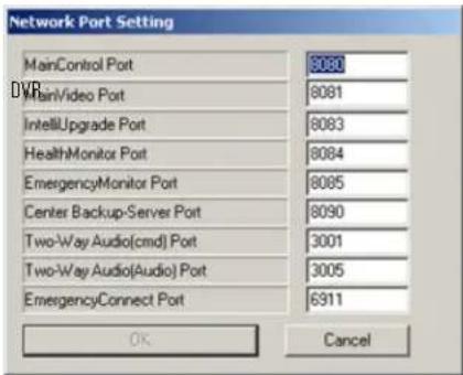
In this menu the network connection ports for ELMO software are configured.

Note
After the network port settings are changed, the system will automatically restart.
3.14.10. Video Loss Alarm
![Video Loss Alarm Enable Alarm Enable Sound Enable Control No. 1 [ Working Time ] 0 0 20](/content/2026/05/941759/images/52ace8357fcc6b33260c1cad06eda890f2654257236a9d11db0a09f3d9db9f7a.jpg)
To configure the Video Loss Alarm menu, do the following:
- Check the Enable Alarm checkbox to activate alarm every time that video loss is detected on any of the cameras.
- Check the Enable Sound checkbox for the audible alarm to sound on PC speaker every time that video loss is detected on any of the cameras.
- Choose the Control from the Enable Control No. drop-down menu to be associated with the video loss. In this example if there is video loss detected on one of the cameras, the Control 1 will turn on (e
- Set the Working Time for the control output and audio alarm. In this example, the Control 1 will stay on and the alarm will sound on the PC speaker for 20 seconds after video loss occurred on one

3.14.11. Select the Num of days to Store Data
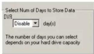
Select the number of days (1 to 30 days) for video recordings to be stored. This option has European customers. Some European countries now have legislation specifying how long a video so can be stored. In Norway, for example, a security surveillance recording can only be stored for is must be deleted. Disable this feature to have video data stored for as long as there is
3.14.12. Video Format

NTSC (North America, most of South America, Japan) video format is supported by ELMO DVR Server, v.5.01. PAL video format |Europe, most other countries| is not supported.
Related Topics: Sensor Setup | Control Setup

Note
The
Storage
ELMO
DVR
Setup
Remote.
tab is NOT
[Non-Text]
is NOT
[Non-Text]
OT available
3.15. Storage Structure Setup
Attention: This function should be used by Authorized Technicians ONLY! The Storage Setup option is used to format
the ELMO DVR hard drive(s) file structure. ALL VIDEO DATA WILL BE LOST! After the drive/pa video data that was recorded on it will no longer be accessible.
Understanding ELMO DVR storage structure:
In order for the ELMO DVR to be able to record video data on a selected drive, the drives/partitions have to be structured in a certain way. After the initial allocation of the specific hard drive/partition, the entire available space is filled with files that have the extensions *.bix and *.box.
These files act as a medium for the digital video recording. The size of these files remains static regardless of whether or not they actually contain video data (*.bix files - 2.5MB, *.box files - 64MB). These files can be compared to video/audio tapes. In both cases, the mediums of recording take up the same amount of space when the contain data.
As the ELMO DVR records video information onto the prepared *.bix and *.box files, they are the video recording. Reallocating the drive will reset this time, and the video recording will be lost. All of the *.bix and *.box files remain on the hard drive after the drive is re-allocated, but they will no longer contain any video data. All days that previously contained video data in the Search window, on the Server, will appear blank.
Allocating the drive does not physically format it. To format the hard drive completely, so that it is no longer allocated for digital video recording, use the appropriate format command from the Windows OS.
3.15.1. Overview
The Storage Structure tab displays the following:
- names of all the drives/partitions
- capacity of each drive/partition
- available space on each partition that can be used by OS (anything other than video reco
- allocation status of each drive/partition

Note
Allocation is not allowed on drives C and D, as those drives are used to store the ELMO software, operating system, and backup folder.
![To modify the storage structure, click the Modify Storage Structure button then restart the system. Upon restart the storage structure dialog box will appear allowing you to make changes to your settings. Drive: [C:] [Available/Total] : [1542 / 5004] MegaBytes Allocation Not Allowed Drive: [D:] [Available/Total] : [9827 / 9991] MegaBytes Allocation Not Allowed Drive: [E:] [Available/Total] : [76 / 15311] MegaBytes Allocated Drive: [F:] [Available/Total] : [171 / 15319] MegaBytes Allocated Drive: [G:] [Available/Total] : [14971 / 15319] MegaBytes Drive: [H:] [Available/Total] : [15294 / 15358] MegaBytes To Modify Storage Structure, Click Button Below. Modify Storage Structure CLOSE](/content/2026/05/941759/images/b9c2c57805bc3832dae7b29d66a00a4a6cbab94bf6d0359126330c2a0072d757.jpg)
3.15.2. Formatting ELMO DVR File Structure
To format the file structure of the selected drives or to allocate new drive for video storage, do the following:
- Click Modify Storage Structure
- Click Yes in the warning window
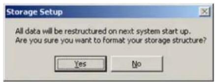
- Close Setup and restart the ELMO DVR Server
- When the server restarts, the Storage Structure dialog box shown below will appear. Click Allocate, next to the drive/partition, to allocate it for video recording, or to format the file structure.
![Storage Structure Following drives are available. To allocate storage structure, click [Allocation] button [The existing data in the drives will be deleted ] Serial Code : (57384850-3974-4E9F-BA77-BFF6D124E9CD) Drive [C:] [Available/Total] : [ 368 / 4000 ]MegaBytes Allocation Not Allowed Drive [D:] [Available/Total] : [ 9656 / 9991 ]MegaBytes Allocation Not Allowed Drive [E:] [Available/Total] : [ 0 / 6040 ]MegaBytes Allocated Allocate Drive [F:] [Available/Total] : [ 48 / 6040 ]MegaBytes Allocated Allocate Proceed(①) Cancel(②)](/content/2026/05/941759/images/0c96803d1d5b4d1065a39b239537a9505e7aac406337abbf750fdb024a6f8c19.jpg)
-
The Allocate button will become Cancel Allocation. New Allocation Space represents the hard drive space that will be used exclusively for video recordings (i.e. will be filled with *.bix and *.box
-
Click Proceed to start the allocation process
-
The Format confirmation window will appear. Click Yes to proceed with formatting.

- The Select file system window will appear. Select NTFS for more security or FAT32 for normal security and click Ok.

- The selected drives will be formatted...

- Once the allocation is complete, the ELMO DVR Server will start normally
3.16. E-Map Setup
3.16.1. Overview

Note
The E-Map tab is NOT available DVR Remote.
The E-Map function allows to lay out cameras on a map for quick launch of a specific car controls and sensors is done on an existing digital drawing/map. The map appears on the main process to the desired camera by simply clicking on its representative icon. Clicking on a camera's icon will display that camera in full-screen mode.
E-map does not allow manual activation of a control. However, if a control/sensor is triggered, the E-map. The icons representing the sensors/controls will be animated. E.g. If the control that turns on the light is activated, the light icon on the E-map will flash.

3.16.2. Drawing a map
Before configuring the E-map function, draw a map of the building in any available image editor or follow the instructions for the Paint editor below. Make sure to save the map in *.bmp format.
-
On the Desktop, click Start > Programs > Accessories > Paint
-
The following window will appear:
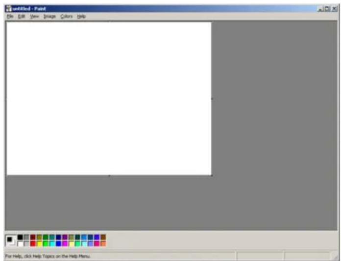
-
Go to View and make sure there is a checkmark on Toolbox.
-
The following Toolbox panel will appear on the left.
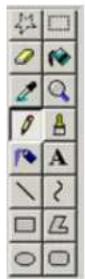
- In the Toolbox panel choose the Rectangle tool and select the rectangle outline below.
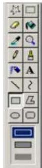
-
To draw the outline of the building/room/warehouse, bring the mouse cursor to the desired Editor. Hold down the left mouse button and drag it to form the box of the desired si
-
Use the Line tool and filled Rectangle tools to draw walls and other objects on the map
-
When finished, Save the drawing.
-
Click File > Save As...
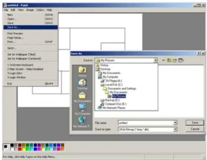
- Choose the desired folder. Name the map. Choose 24-bit Bitmap in Save as type and click Save.

3.16.3. Configuring Emap
To configure the E-Map in the ELMO DVR Server, do the following:
-
Open ELMO DVR Server Setup and go to the E-Map tab.
-
Click Enable E-map to activate the E-Map on the main screen.
-
Choose the Screen Division in which the E-Map will appear.
-
Choose the Position No. (screen) number in which the E-Map will appear on the main screen. In this example, ELMO DVR will display the screen division for 4 cameras with the E-Map being displayed itions with configured E-maps will be checkmarked

At any time during the E-Map configuration, the current E-Map can be saved to the same to the position chosen by the user.

- Click Find >> to find the bitmap image to load into the E-Map.

-
Click Go! to copy the selected image to the drawing area. The Image will appear on the left side of the Setup window.
-
In the Setting menu, choose Camera, Control or Sensor, the number and type of Camera/Control/Sensor that is to be positioned on the E-Map.

Camera:
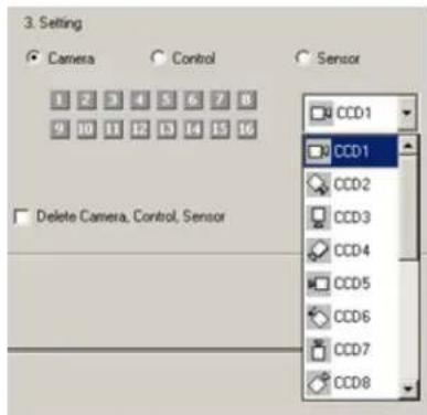
To add the camera icon on the E-map, do the following:
a. Select the Camera radio button
b. Choose the number and the type of camera from the list. The icons account for the is pointed
c. After choosing the camera number and type, click on the E-Map bitmap image where the camera icon will be added onto the image.
Control:

To add the camera icon on the E-map, do the following:
a. Select the Control radio button
b. Choose the number and the type of control (Light and Alarm icons are available) from
c. After choosing the control number and type, click on the E-Map bitmap image where th The control icon will be added onto the image.
Sensor:
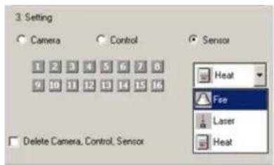
To add the camera icon on the E-map, do the following:
a. Select the Sensor radio button
b. Choose the number and the type of sensor (Fire, Laser and Heat icons are available) f
c. After choosing the sensor number and type, click on the E-Map bitmap image where the control icon will be added onto the image.
- Click Save to save the E-Map Setup settings. After all the cameras, sensors and controls are positioned on the map, it will look something like this:

natural_image
Simple layout diagram with a red square and surrounding icons, no text or labels present.3.16.4. Delete Cameras/Controls/Sensors from Emap
To delete Cameras/Controls/Sensors do the following:
- Check the Delete Camera, Control, Sensor checkbox in the Setting menu
- Click the camera, control or sensor icon on the E-Map to be deleted. The icon will disa

Note
Do no switch between screen divisions or positions without saving the settings.
3.16.5. Delete/Change the E-Map bitmap image, do following
To delete/change the E-Map bitmap image, do the following:
- Check the Delete Image checkbox in the Setting menu.
- Click on the E-Map bitmap image on the left side of the Setup tab.
- Click Save. No image will be displayed in the E-Map Setup tab.
- Click Find >>, choose the new bitmap image and click Go!
3.16.6. E-Map on the Main Screen
Close the Server Setup to access the main screen. The E-Map will be displayed in the chose Screen Division:
Click on the E-Map image to bring the E-Map to the full-screen mode. Left-click again to ret mode. By clicking on the camera icon on the E-map (either in full screen or Screen Division camera will be brought to the full-screen mode.
Related Topics: Main Screen | Sensor Setup | Control Setup
3.17. View Log Records
3.17.1. Overview

Note
The View Log Records tab is NOT on ELMO DVR Remote.
Once the user accounts are set, the Manager can track user activity in the View Log Record be erased from the ELMO DVR, however there is no way to alter the Log Records. Log R activities: changes in any of the setup tabs, sensor activation, sent E-mails, video loss, storage structure modification, etc. The logs can be viewed in the Setup menu or exported to the text file.
All log activities are stored and organized according to date.

3.17.2. Viewing Log Records
To view and export specific log files, do the following:
- Click the plus sign (+) next to 'Log Records' to view the months that have log records
- Click the plus sign (+) next to the desired month to view all entries for that month
- Select the log filename to view a particular day (yyyy-mm-dd)
- The activity log will appear on the right-hand panel
- Click Export in the bottom of the screen to export a log to a text file
- Choose the destination folder for the log text time
- Name the log text file

- To view the log text file, locate the exported log file in the destination folder and double-click it. The log file will open in the Notepad application.
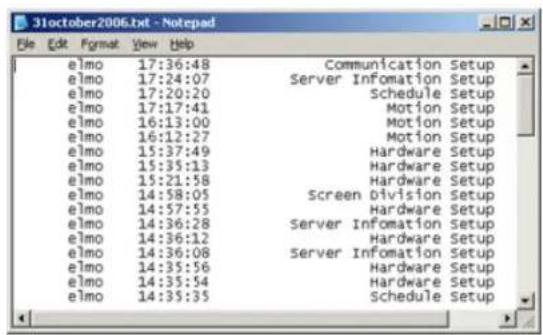
3.18. Email Setup

Note
The Email tab is NOT available DVR Remote.
on ELMO
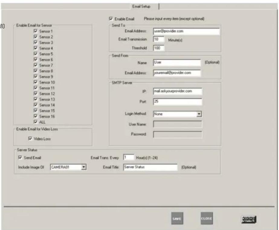
3.18.1. Overview
This Setup tab allows sending an alert via email when a sensor is triggered, or when a video signal has been lost. It can also send the status of the Server by sending a screen shot from a specified camera.
Three ways to send an email alert:
1. Triggered Sensor(s)
Select appropriate sensors in the Enable Email for Sensor menu. Whenever any of the selected sensors are triggered, an e-mail alert will be sent to the configured e-mail address.
2. Video Loss
Check the Video Loss checkbox in the Enable Email for Video Loss menu. Whenever video loss is detected on one or more cameras, an e-mail alert will be sent to the configured e-mail address.

Note
Make sure the sensors are enabled and configured in the Hardware Setup.
- Enable Email for Video Loss
Video Loss
3. Scheduled Server Status
Scheduled e-mails to provide server status: an e-mail and snapshot from the specified camera To have ELMO DVR send the server status e-mails, fill in Server Status menu:

a. Check the Send Email checkbox to enable server status e-mail alerts
b. Select the frequency of the automatic e-mails (1-24 hours) in the Send Email Every x Hour(s) field
c. Choose the Camera in the Include Image Of field. A snapshot from this camera will be sent to the configured e-mail address.
d. Enter the Email Title for the server status e-mail alerts (Optional)

Note
A first e-mail is sent after changes to this setting are saved and on the ELMO DVR Server startup. The ELMO DVR Server will then send e-mails according to the set schedule. In this example, every hour.
3.18.2. Configuring Email Setup
-
Check the Enable Email checkbox
-
Fill in the Send To section:

- Enter the Email Address of the recipient. Optionally, multiple email addresses can be entered. Separate multiple e-mail addresses by commas or semi-colons.
- Enter the Email Transmission Delay. This option sets the delay time in minutes that will pass after the sensor has been triggered before the transmission will start.
- Enter the Threshold number. This value sets the number of event lines to be included in the sent emails. Depending on the settings, numerous events can be registered by the Server: detected motion activated control, video loss. Each event can be reported individually by e-mail, however, thisient e-mail inbox; as a means to avoid this, multiple events (lines) can be sent in a

Note
When setting the Threshold number, remember that an e-mail will not be sent until necessary number of events has occurred to reach the threshold.
- Fill in the Send From section:

- Enter the Name of the sender (Optional).
-
Enter the Email Address of the sender.
-
Fill in the SMTP Server section: Depending on the location, each Internet provider has specific SMTP information. Obtain this information from the Internet provider.

a. Enter the IP Address of the SMTP server. Example: smtp.bellympatico.com
b. Enter the Port number. It is not usually necessary to change the port number. Most SMTP servers have a default port. For more information on default Ports, please contact the email account manager.
c. Enter the Login Method. "None" is the default method; otherwise, please contact the email account manager.
d. Enter the User Name and Password: Some Internet providers require user names and passwords to send out emails, if this is the case, please enter them accordingly.
Related Topics: Sensor Setup | Intelli-Guard™ | VideoLogix™
3.19. Intelli-Guard™
3.19.1. Overview
Intelli-Guard™ is an exclusive intelligent feature offered by ELMO USA CORP. The Intelli-Guard™ fe and counts passing objects within a defined area of the camera's view and can respond by a mail or a phone call. Intelli-Guard™ requires precise settings in order to work effectively.
Intelli-Guard™ detects change in an image by analyzing its pixels. The same principle is used b feature. However, Intelli-Guard™ can yield a more precise response than Motion Detection, as it ferent kinds of motion. For instance, an object's size and direction of movement can be used of an alarm. Motion Detection, on the other hand, recognizes and registers any type of motion
Note that Intelli-Guard™ uses the e-mail address configured in the Email Setup and the Emergen figured in Communication Setup. Make sure to configure the appropriate Setup tabs.
Intelli-Guard™ provides two types of motion detection: Surveillance (up to 6 target zones) and C zones).
Important: Count is only available when PACDM™ is installed. The Surveillance motion detection mode is the default option for the ELMO DVR with no PACDM™ installed. The Surveillance type of motion detection alarm, an emergency E-mail or a phone call in response to the detected motion. The Count counts the number of motions in the specified region and exports this data to the database.
- Example of Surveillance type of motion detection: a motion detected in the restricted area trigger an audio alarm, emergency E-mail or a phone call.
- Example of Count type of motion detection: ELMO DVR will count the number of cars en "Drive Through". This number is then exported to the database and can provide the managers with important statistics for use in strategic marketing.
Up to 6 Surveillance target zones (Areas) and up to 3 Count detection zones (Gates) can be set for each individual camera.
Every detection/target zone has its own parameters that have to be adjusted and saved individual

3.19.2. Suggestions for using Intelli-Guard™
- Before setting a defining area or Gate, experiment at the specific location to test the par that the Intelli-Guard works as expected. Test both real alarm and false alarm situations. Adj imize / illiminate the number of possible false alarms.
- It may be difficult to achieve good results if the image video contrast is low. Adjust the image brightness and contrast to achieve better results.
- Intelli-Guard™ is best used in an environment with little color variation. For instance, if the monitored object is placed on a one-color background, any change (e.g. intruder) will be noticeable, therefore easily detected option, it is most efficient to mount the camera on the ceiling facing down, so that the direction of the motion is easily traced.
3.19.3. General Intelli-Guard™ configurations
- Click the desired camera number. The selected camera will be displayed in the live view:
- Adjust the camera's Brightness/Hue/Contrast in the Individual Camera Adjustment menu
- Click Default to reset the Brightness/Hue/Contrast values

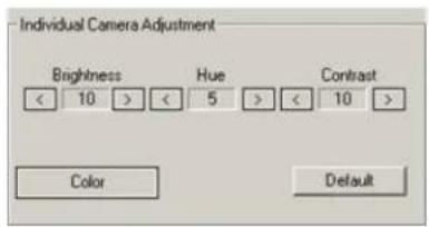
- Choose between Monochrome and Color modes of recording
- Choose the Control Output for the Intelli-Guard. When the alarm is triggered through the Intelli-Guard, the selected control will be activated.
Mo-

- Choose Surveillance or Count
3.19.4. Surveillance target zone (Area) configurations
Each target zone has its own configuration and has to be saved individually. The Area menu specifies which target zone is currently selected. To switch between target zones, select the chosen target zone by clicking live view screen.
- Define the target zones in the live view screen on the left. Up to 6 target zones (Are
a. Place the mouse cursor at the start point over the live-mode camera view on the left
b. Hold down the left mouse button and drag the cursor to draw the rectangular target
c. Let the mouse button go
d. Adjust or move the created target area if necessary
- Check the Send Email checkbox to have an emergency Email sent every time that the alarm is triggered in this Area. The email address used, is from the Email Setup tab.
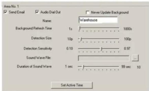
- Check the Audio Dial Out checkbox to make an emergency phone call every time that the alarm is triggered in the Area. Emergency phone numbers are taken from Communication Setup tab.
-
Name the specified Area. In this example, Area No. 1 is labeled as "The Door"
-
Set the Background Refresh Time (1s - 1800s). If Intelli-Guard™ detects no changes in the monitored area, it will update the area picture according to the selected schedule. This will decrease frequency caused by normal occurrences, such as changing illumination across the period of a c time is set to 20 seconds. It can be adjusted from 1s to 1800s. To keep the same t Never Update Background checkbox.
-
Configure Detection Size (10p - 100p). This parameter determines the number of pixels representing 1 (one) "block". At least one block has to be detected by Intelli-Guard to trigger the alarm. The smaller the size of the block, the more "sensitive" will Intelli-Guard become and the smaller the size of the objects that will set off the alarm.
For instance, assume that a bird occupies 10 pixels in a resolution of 720x480. If the Detection Size is set to 10 pixels, the bird will represent 1 block; therefore the alarm will be triggered. However, if the Detection Size is set to 20 pixels, the bird will no longer represent 1 block and will be omitted by the Intelli-Guard. A larger Detection Size, thus, detects larger objects (e.g. people) and omits smaller ones. This setting is used to decrease the nu configuring this setting, it is important to run trials to ensure that the Detection size is reacting to objects of a desired size. On the screen, the area of a detected change will be indicated by, green outline wi indicates how many detection blocks make up the area.
In the example below, motion was detected in an area, which is made up of 5 detection of detection blocks shown on the live view screen, click Show Objects. To hide them, click Hide Objects.
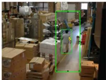
natural_image
Warehouse interior with stacked boxes and a worker walking through the aisle (no visible text or symbols)-
Configure Detection Sensitivity (10% - 97%). This parameter accounts for the even (global) change in image brightness. This percentage determines the acceptable level of brightness change. If the illuminati slowly and evenly, it is unlikely to cause an alarm. However, if the light switch is sudden the dramatic change in image brightness will set off the alarm.
-
Select the Sound Wave File for the audio alarm
a. In the Area menu, locate the Sound Wave File field
b. Click the Browse button ⋯ to locate the *.wav sound file that will play every time that the alarm is triggered.

c. Click Open
d. Check or Uncheck the Audio Dial Out checkbox
If the Audio Dial Out checkbox is checked, the chosen *.wav file will be played as a message for the emergency phone call.
If the Audio Dial Out checkbox is unchecked, the file will only be played locally on the ELMO DVR.
-
Set the Duration of Sound Wave (1 sec - 99 sec) to determine how long the
-
Set Active Time. The specific target Area will only be active during the selected times


- Click Save to save the selected area configurations
IMPORTANT: Ensure there is NO MOTION occurring in the defined area when clicking Save, otherwise the Intelli-Guard™ function will not work properly for that area. The reason for this is that the detect motion itself, but changes in the pixels that make up an image. When Save is clicked, Intelli-Guard™ registers the current image as the default image. All consequent changes to that area will be registered the defined area when the Save is clicked, even the static environment will set off the
-
To delete one defined target zone, select the area by clicking on it, hold down the left mouse button and drag the area to remove it from the live view screen.
-
To delete all defined target zones, click Reset
-
To delete all defined target zones and select the entire camera view for motion monitoring, click Reset & Add All
3.19.5. Count target zone (Gate) configurations
Each target zone has its own configuration and has to be saved individually. The Gate menu specifies which target zone is currently selected. The Count target zone not only detects the motion, but also detects the direction of the motion.
The Count target zone is shown as a green arrow with a red number in the middle. The detected motions moving in this direction. To switch between the target zones, click the desired the live view screen.
-
Define the target zones in the live view screen on the left. Up to 3 target zones (Gat
a. Place the mouse cursor at the start point over the live-mode camera view on the left
b. Hold down the left mouse button and drag the cursor to draw the rectangular target
c. Let the mouse button go
d. Adjust or move the created target area if necessary -
Name the specified Gate. In this example, Gate No. 1 is labeled as "Gate1"
-
Set the Background Refresh Time (1s - 1800s). Same as Surveillance target zone (Area).
-
Configure Detection Size (10p - 100p). Same as Surveillance target zone (Area).
-
Configure Detection Sensitivity (10% - 97%). Same as Surveillance target zone (Area).
-
Configure Object Speed (20p - 300p). The Object Speed value determines the speed at which the object has to be moving in order to be counted by the Count option.
Object Speed:
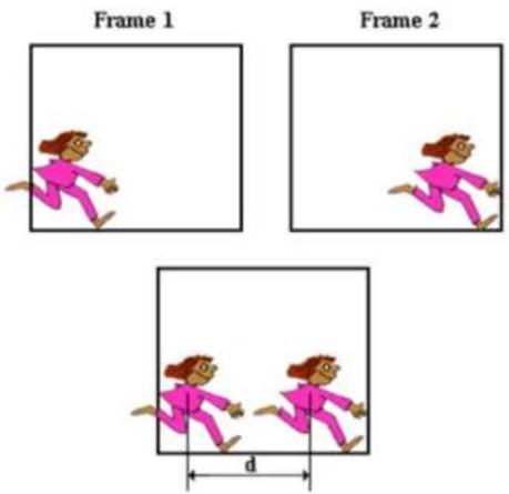
When motion occurs on the screen, ELMO DVR analyzes consecutive frames, in which motion whether the occurred motion(s) represents one same object.
The only way this could be determined is by the speed with which the object moves aci on the left, two consecutive frames are analyzed. The distance that the object has traveled frames equals d.
In order to be counted as a single object, the distance that the object travels between 2 than the Object Speed parameter value. If the distance traveled exceeds the Object Speed, the motion
will not be counted as an object. Since ELMO DVR analyzes digital images, the distance is -300 pixel.
If the Object Speed is set to 40 pixels, and the moving car has traveled 45 pixels on frames, it will not be counted. The Object Speed has to be set based on experiment. The environment and customer needs.
- Set the Activity Weight (1-10) The Activity Weight option is for adjusting the number of blocks that will set off the alarm. For example, if the Detection Size of one block is set to 10 pixels, and it will take at least 3 blocks (30 pixel) for the alarm to go off.
- The Gate is represented with the green arrow pointing in one direction with the number shows how many times the motion was detected in the specified direction. To reset the number, click Reset.
- Click View Record to see when a motion was detected on a specified Gate. This data is exported to the database. Earlier data can be accessed through a calendar.
- Click Save to save the selected Gate configurations.

Note
Ensure there is NO MOTION occurring in defined Gate when clicking Save, otherwise the Intelli-Guard™ function will not work properly for that Gate.
To delete one defined target zone, select that Gate by clicking on it, hold down the left arrow off from the live view screen to remove it.
- To delete all defined target zones, click Reset
3.19.5.1. Suggestions for using Object Speed
- To detect slow moving objects, the Object Speed has to be set to a lower value
- To detect fast moving objects, the Object Speed has to be set to a larger value
- If the Object Speed value is too low, Intelli-Guard will not count fast moving objects
- If the Object Speed value is too high, two unconnected motions on the screen might be This will cause the counter to increase continuously.
Related Topics: Control Setup | Communication Setup | Email Setup
3.20. Virtual Ruler
3.20.1. Overview
With this feature it is possible to approximate the height of a person once they are in the camera's view. During playback, the person's height can be estimated with regard to the virtual ruler. (In the example below, the ruler is 7' long with a division value of 1'.)

3.20.2. Configuring Virtual Ruler
To set up the Virtual Ruler for a camera, do the following:
-
Select the Camera for which the ruler will be inserted.
-
Select the Color {Black or White} of the ruler and the Start/End point values that will be shown on the screen. Choose the color that will best contrast with the background.
-
In the Degree menu, enter the Start Point value of the ruler. This number will be shown at the ruler's beginning.
-
In the Degree menu, enter the End Point value of the ruler. This number will be shown at the ruler's end.
-
In the Degree menu, enter the Division value, which is the value of one ruler division. This number has to be smaller than the length of the ruler, or will be assigned the same value as the length is the distance (in chosen units: feet, meters, etc.) between two dividers. To obtain the total number of ruler divisions, the length of the ruler is divided by the Division value.
-
The smaller the division value, the more divisions there will be on the ruler. The ELMO adjust the division value if the length of the ruler can not be equally divided by the sp
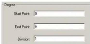
- In the Unit section, select the desired unit of measurement: feet, inches, meters, etc.
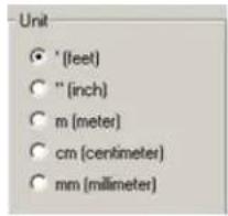
- Draw the Virtual Ruler in the live view screen.
To draw a Virtual Ruler, do the following:
- Physically measure the height or the area covered in the camera view
- Draw a mark(s) on that area to signify the start and end points of the ruler
- Using the mouse, move the cursor to the live view screen in the Virtual Ruler Setup ta
- Hold down the left mouse button, and drag it in a straight line
- Adjust or move the ruler if necessary
- To erase the ruler click Clear
Example,
In the following example the height of the person is exactly 72 inches. The ruler starts with 72". The unit of measurement is inches. The division value equals to 12 inches, thus dividing the virtual ruler into 6 equal parts.
![Degree Start Point: 0 End Point: 72 Division: 12 Unit "(Ieel) "[inch] m (meter) cm (centimeter) mm (millimeter)](/content/2026/05/941759/images/42d516210e5b55efce4c365108a0f466be369ea0bf319822611588373b97af17.jpg)
Related Topics: Main Screen
3.21. Intelli-Zone™
3.21.1. Overview
Intelli-Zone™ is another exclusive intelligent feature offered by ELMO USA CORP. Intelli-Zone™ is a the camera to intelligently pan, tilt, or zoom to a specified preset. The ELMO DVR Server will automatically detect if that camera has P/T/Z features and adjust the pan-, tilt-, or zoom- settings where applicable. In comparison to Motion Tracking, Intelli-Zone™ does not provide real-time motion tracking. Instead, it offers a simulated motion tracl

To set up Intelli-Zone for each camera, do the following:
- Enable Intelli-Zone by checking the Enable Intelli-Zone checkbox.
- Click the desired camera number that Intelli-Zone will be configured for. The selected camera will be displayed in the live view screen on the left.
- Select the Start Position's preset. This is the position the camera will return to after the specified dwell time.
- Configure up to 10 desired Presets in the P/T/Z Control menu. The presets previously configured in the P/T/Z mode can also be used
- Set the Active Time to enable Intelli-Zone on the selected camera. Intelli-Zone will not work outside of the set Active Time. This value will be the same for all target areas on one given camera.
-
Adjust Sensitivity. This value will be the same for all target areas on one given camer
-
Set the Refresh time. Refreshing an image more often will decrease the cumulative image difference caused by normal occurrences, such as changing illumination across the period of a day and will reduce alarms. This value will be the same for all target areas on one given camera.
3.21.2. Setting up Intelli-Zone target areas
To Set up Intelli-Zone target areas, do the following:
- Draw a target zone on the selected camera (up to 10 zones can be defined per camera
a. Place the cursor over the start point on the live view screen
b. Hold the left mouse button down and drag to create a rectangular area
c. Let the mouse button go
d. Move/adjust the area if necessary
e. To delete target zone, click a target zone to select it, hold the left mouse button do off from the live view window.
f. To erase created areas, click Reset All Areas - Select the specific target area by clicking on it in the live view window.
- Enter the Area Name for the created target zone in the Detection Zone menu.
- Check the Display Area Name checkbox to display the Area Name on the main screen each time the motion is detected in that area.
- Select the Go to Preset position. The camera will move to this position when motion is detected.
- Set the Block Count number by clicking up and down with the arrows. The Block Count number determines the detection sensitivity of the target zone. One block is 10-pixels high and 10-pixels wide. number, the more significant a change must be in an image to set off the alarm. The cannot be manually changed and depends directly on the block count number. Percent of ChCount as a percentage, as opposed to blocks.
- Enter the Dwell Time. This defines the delay time before the camera returns to the Start Position.
- Assign the Control Output that will be triggered by the motion detected in the target area. The control has to be available and activated in the Hardware Setup.
To associate a target area with another camera, do the following:
-
In Associated with Camera menu, choose the associated camera in the Camera field. This camera will assume the selected preset when motion is detected in the specific target area.
-
In Associated with Camera menu, in the Preset Number field, choose the Preset position that the associated camera will go to once motion is detected in the target area.
In the example above,
If a change of at least 5 blocks (5% of the total target area) occurs in the target area labeled "Door", Camera 1 will go to Preset 02, Control 2 will be activated, and the camera labeled Front Door will move to the camera will return to the Preset 01.
Related Topics: PTZ mode | Control Setup
3.22. Motion Tracking
3.22.1. Overview
Motion tracking is a real-time tracking technology offered by supported cameras. When a camera tracking, the camera moves to the location of the object detected in the target zone. In order you must first select a camera which supports motion tracking.

To set up motion tracking on a camera, do the following:
- Select the desired camera.
- On the video window, move the mouse to the start point. Hold down the left mouse by draw a rectangular 'box' (target zone).
- In the Enable Camera section, select the camera from the Current Camera drop-down list.
- Click the numbered button to enable the selected camera.

Note
You must have a camera that tion tracking before any cameras available.
supports mo- will be a. Set the PAN and TILT respectively.
b. Click Screen Value to get the current position of the camera.
c. Click Move Camera to move the camera to your new position.
d. Set the Return Start Position time in seconds for when to move the camera back to the original Start Position, after the camera stops tracking motion.
- Define the Range.
a. Set the PAN to move left and right. The camera moves from the Start Position that you pre-set. The minimum value to the left and right is 40 degrees. The sum of value to the left and 360 degrees. If the sum of both values exceeds 360 degrees, then the value will be
b. Click Screen Value to get the current camera position.
c. Click Enable to activate the panning range.

Note
Using the PTZ controls will stop tracking. This is the reason for
d. Set the minimum angle of the TILT based on the value you placed in the Start Position.
e. Click Screen Value to get the current minimum value of the TILT .
f. Click Enable to let the camera move within the value of the angle.
7. Define On/Off Time
a. Set the time for which to activate the Motion Tracking function. The default value is 00:00 \~ 00:00. The camera works in PAN/TILT mode outside of the configured time.
b. Click Disable PTZ Mode : to disable PTZ mode from the motion tracking camera. If you don't select this option, both motion tracking and PTZ will be used.
- Define the Set Values
the motion Disable PT2a. Adjust the PAN Angle to set the value when the selection box is not in correct
b. Adjust the Tilt Angle to set the value when the selection box is higher or lower than the position chosen.
c. Increase or decrease the Sensitivity of the camera movement. You will need to adjust this value properly depending on the location. Note that motion tracking may become sensitive to light, and
d. Enabling Camera Flip will allow a PAN/TILT camera to maintain an upright viewing position. For example, the image will not be inverted.
Related Topics: Motion Detection | Intelli-Guard™
3.23. VideoLogix™ Setup
3.23.1. Overview
VideoLogix™ is an intelligent human{vehicle} tracking/theft detection module developed exclusively by E. This module allows:
- Detecting Human Presence
- Detecting a Vehicle
- Detecting Missing Object
- Analyzing Human/Vehicle behaviour
- Initializing pre-selected response depending on the nature of the behaviour
To use VideoLogix™ module, your system must meet the following requirements:
For 1 channel of VideoLogix™:
• CPU: Pentium 4, 2.4 GHz or above
• RAM: 512 MB
- OS: Windows XP Pro
For 4 channels of VideoLogix™:
• CPU: Pentium 4, 3 GHz or above
- RAM: 1GB
- OS: Windows XP Pro
New systems come with 1 free channel of VideoLogix™. It is possible to upgrade to the tot channels. Please note that it will also require necessary hardware upgrades in order to meet t requirements. After the purchase of additional VideoLogix™ channels, call technical support to obtain add the additional VideoLogix channel(s), click Update License in the VideoLogix™ Setup and enter the new License Key.
The VideoLogix™ tracking module is a versatile device that allows for seven different types of and tracking: Area, CrossWire™, Idle, Missing, Stop, Direction, Passthrough Counter™.

3.23.2. Configuring VideoLogix™

Note
Configure each Videologix™ channel ately.
separ-

To configure the camera settings, do the following:
- Click the desired camera number. The selected camera will be displayed in the live view:
- Check the Enable VideoLogix checkbox to enable the VideoLogix™ module for the selected camera. In the example above, VideoLogix™ is configured for Camera 1.
-
Set the Hue, Brightness and Contrast for the selected camera as desired.
-
Click Default to reset the Hue, Brightness and Contrast values back to 0.
-
Click Color/Monochrome to choose between color and monochrome recording. Color recording provides realistic video images. Monochrome is best suited for low light conditions, such as nighttime
- Choose the Control Out in the drop-down menu for the selected VideoLogix™ channel. When the alarm is triggered on the selected VideoLogix™ channel, the configured control will be activated. In the 1 will turn on when the VideoLogix™ alarm is triggered.
- Set Object Min Size. This pixel value is the minimum size that the human form has to represent on the live-view screen in order to be detected by VideoLogix™. By default, this value is set to the 10 pixels. Any objects smaller than the selected object minimum size will not be recognized.
- If necessary, configure the environment for the selected camera. Check Overhead Camera checkbox if the selected camera is facing downwards. Check Crowded checkbox if the selected camera is mounted in a crowded location. Please note that only one checkbox can be selected.

Note
The maximum frame per second rate cameras configured for Videologix™ fps.
on the is 13
- Check the Hide Detection Box checkbox in order to hide the detection box on the After configuring the common channel settings, choose and configure the desired type of human/ol

Note
The environment limitations, such as restricted camera view due to the mounting location or the crowded site will restrain Video-Logix™ functionality. I.e. If Overhead Camera is checked, only Missing and Passthrough Counter alarm options will be available. If Crowded is checked, only Direction alarm option will be available.
3.23.3. Configuring Object/Alarm type
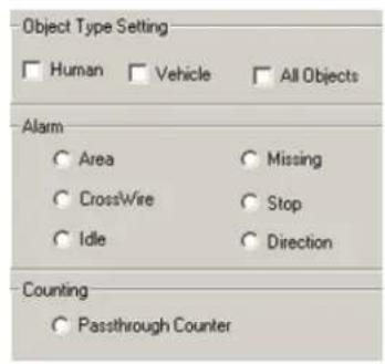
To configure the Object/Alarm type, do the following:
- Choose the Object Type between Human, Vehicle or All Objects.

Note
Human and Vehicle object types can be combined
- Choose the Alarm type from seven possible choices:
a. Area (not available when Overhead Camera or Crowded options are checked)
b. CrossWire (not available when Overhead Camera or Crowded options are checked)
c. Idle (not available when Overhead Camera or Crowded options are checked)
d. Missing available only for All Objects object type. Not available when Crowded option is checked
e. Stop (not available when All Objects object type is selected. Not available when Overhead Camera or Crowded options are checked)
f. Direction (not available when Overhead Camera option is checked)
g. Passthrough Counter (not available when Crowded option is checked)
3.23.3.1. Configuring Area alarm
The Area alarm detects the human / vehicle / object presence in the defined area and initiat
Please note that the Area alarm option will not be available for the overhead-mounted cameras and in the crowded locations.

Note
Due to the background registration technique the persons, who remain in the position, without moving, for an extended period of time will not be detected.
To configure Area alarm, do the following:
- Choose
Area in the Alarm menu.
2.

- Draw the detection zone in the live view screen. A total of three Area alarm detection gular, polygon or both.
a. For rectangular area: Click on the live view screen to define the area starting point, hold down the left mouse button and drag to draw a rectangular area.
b. For polygon area: Click on the live view screen to define each vertex of the polygon. Click on the first point defined to complete the polygon.
c. To adjust the detection zone position on the screen, click on the desired detection zone, down and drag the selected zone to the desired position.
d. Click Undo to delete the last detection zone
e. Click Clear to delete all detection zones for the selected camera
f. Name the detection zone in the Area field if required. Enter the desired name in the text field under the live view window.

- Set the Active Time for each detection zone. In the example below, the Area alarm is active from 8 AM to 5 PM.

Note
Active Time must be configured. Unless the Active Time is set, object detection will not occur in the selected area.

- Configure the Alarm Output Setting for the selected detection zone
a. Check the Send Email checkbox to send an emergency Email every time that the alarm is triggered in this detection zone. The email address is must be configured in the Email Setup tab.
b. Check the Audio Dial Out checkbox to make an emergency phone call every time that the alarm is triggered in the Area. Emergency phone numbers must be configured in the Communication Setup ta
c. Select the Sound Wave File for the audio alarm

Note
If the Audio Dial Out checkbox is enabled, the chosen *.wav file will be played as a message for the emergency phone call.
i. Click the Browse button ⬆ and locate the *.wav sound file that will play every time that the alarm is triggered
ii. Click Open
![Area0 OutPut Setting Send Email Audio Dial Out Sound Wave File: C:\WAV\cameraclick Duration of Sound: 30 Second(s) Open Look in: WAV cameraclick greeting File name: cameraclick Files of type: WAV file["wav"] Open Cancel Open as jead-only](/content/2026/05/941759/images/8731a62b99388e3704671c84ee17e20445ee728f4304ddf4de947cd8d47e47f6.jpg)
-
Set the Duration of Sound (1 - 100 sec) to determine how long the *.wav file v
-
Configure the Area Alarm Setting for the selected detection zone by selecting one of the following conditions:

a. In the Condition drop-down menu, choose any to trigger an alarm every time human/vehicle/object presence is detected in the defined area.
b. In the Condition drop-down menu, choose " = " (equal to) in the drop-down menu and enter the desired number of persons/vehicles/objects. This way the alarm will be triggered only if the specified number jects is met in the defined area.
c. In the Condition drop-down menu, choose “> =” (greater or equal to) in the drop-down menu and enter the desired number of persons/vehicles/objects. This way the alarm will be triggered only if the persons/vehicles/objects is met or exceeded in the defined area.
3.23.3.2. Configuring CrossWire alarm
The CrossWire alarm detects any human/vehicle/object that is crosses the specified boundaries in a predetermined direction and initiates an alarm.
Please note that the CrossWire alarm option will not be available for the overhead-mounted cam locations.

Note
Due to the background registration technique the persons, who remain in the position, without moving, for an extended period of time will not be detected.
To configure CrossWire alarm, do the following:
-
same Choose CrossWire in the Alarm menu
-
Choose the CrossWire drawing tool
-
Draw the detection zone in the live-view window. A total of three CrossWire detection alar
a. Click on the live view screen to define the starting point
b. Hold down the left mouse button and drag the cursor to set the end point. The arr in the desired location.
c. To adjust the detection zone position on the screen, click on the desired detection zone, down and drag the selected zone to the desired position.
d. To adjust the detection zone, click on start/end point, hold down the left mouse button and drag in desired location to expand/shrink or change the direction of the CrossWire detection zone
e. Click Undo to delete the last detection zone
f. Click Clear to delete all detection zones for the selected camera
g. Name the detection zone in the Area field if desired
- Repeat steps 4-6 of the Area alarm setup
3.23.3.3. Configuring Idle alarm
The Idle alarm detects a human/vehicle/object and initiates an alarm if the detected object remains for a period of time longer than that defined by user.
Please note that the Idle alarm option will not be available for the overhead-mounted cameras and in the crowded locations.
To configure Idle alarm, do the following:
- Choose Idle in the Alarm menu
- Repeat steps 2-6 of the Area alarm setup
- Configure the Idle Alarm Setting for the selected detection zone. Set the Period of Time, in hours, minutes and seconds that an object is allowed to remain in the defined area. Once the p exceeded the allowed period of time, the alarm will be triggered.
In the example below, the alarm will be triggered if the person remains in the defined a

3.23.3.4. Configuring Missing alarm
The Missing alarm tracks any selected object and initiates an alarm if the object has been removed/moved from its original position.
Please note that the Missing alarm option will not be available in the crowded locations.
To configure Missing alarm, do the following:

Note
All Objects must be chosen in Type menu in order to activate alarm type.
the Object Missing 3.
-
Choose Missing in the Alarm menu
-
Repeat steps 2-6 of the Area alarm setup
Configure the Missing Alarm Setting for the selected detection zone. Set the Area Change Percent (0% - 100%). The higher the number, the more profound the change in the defined area the alarm. To detect the item being moved slightly from its original position, the Area Change Percent number should be set to a lower value.

3.23.3.5. Configuring Stop alarm
The Stop alarm detects a human/vehicle and initiates an alarm if the detected human/vehicle sto for a period of time longer than that defined by user.
Please note that the Stop alarm option will not be available for the overhead-mounted cameras and in the crowded locations.

Note
Human or Vehicle must be chosen in the Object Type menu in order to activate Missing alarm type. Stop alarm will not 2. work with All Objects object type.
To configure Stop alarm, do the following:
Choose Stop in the Alarm menu
Repeat steps 2-6 of the Area alarm setup
- Configure the Stop Alarm Setting for the selected detection zone. Set the Period of Time, in hours, minutes and seconds that a human/vehicle is allowed to stop for in the defined area. Once in the defined area for the period of time longer than defined by user, the alarm will I In the example below, the alarm will be triggered if the human/vehicle stops in the defined seconds.

3.23.3.6. Configuring Direction alarm
The Direction Alarm detects any human/vehicle/object that moves in a predetermined direction and Please note that the Direction alarm option will not be available for the overhead-mounted came

Note
Due to the background registration technique the persons, who remain in the position, without moving, for an extended period of time will not be detected.
To configure Direction alarm, do the following:
- Choose Direction in the Alarm menu
Choose the Direction drawing tool
- Draw the detection zone in the live-view window
a. Left-click on the live view screen to define the starting point
b. Hold down the left mouse button and drag the cursor to set the end point. The arr direction.
c. To adjust the detection zone position on the screen, hold the left mouse button down to the desired position.
d. To adjust the detection zone, click on start/end point, hold down the left mouse button direction to expand/shrink or change the direction of the CrossWire detection zone
e. Click Undo to delete the last detection zone
f. Click Clear to delete all detection zones for the selected camera
g. Name the detection zone in the Direction field if desired
- Repeat steps 2-6 of the Area alarm setup
3.23.3.7. Configuring Passthrough Counter alarm
The Passthrough Counter alarm detects any human/vehicle/object that is moving in a defined direct and stores it in the Access database.
Please note that the Passthrough Counter alarm option will not be available in the crowded lo
To configure Passthrough Counter alarm, do the following:

Note
Due to the background registration technique the persons, who remain in the position, without moving, for an extended period of time will not be detected.
-
Choose Passthrough Counter in the Counting menu.
-
Repeat steps 2-3 of the Direction alarm setup.
-
Repeat step 4 of the Area alarm setup.
3.23.4. VideoLogix on the Main Screen
The Main Screen displays all configured VideoLogix™ detection zones along with the assigned nam-triggered in one of the specified zones, in one of the specified zones, the Alarm icon is dis
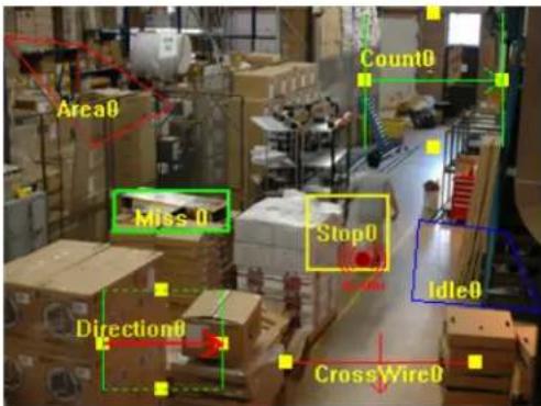
3.24. Snapshot Setup
3.24.1. Overview
Snapshot setup allows the user to configure the default location and the default file name for
When the Snapshot button is clicked on the main screen, the ELMO DVR will take the snap cameras and save them to the destination specified in this setup page. The embedded text and are also configured in the Snapshot setup page.
3.24.2. Configuring Snapshot Setup

To configure the Snapshot setup, do the following:
-
Check the Enable checkbox for all cameras that will be used with the Snapshot feature. Check the All Cameras checkbox to enable all cameras. When the Snapshot button is clicked on the main screen, the snapshots from enabled cameras will be taken. If no cameras are enabled in the Snapshot Setup, the Snapshot button on the main screen will not work.
-
Set the File Name Extension to File Name, Suffix, or Prefix. This feature allows customizing the snapshot name for easy classification.
a. File Name extension:
The text entered in the File Name field will be used in the snapshot file name. In the example below, the snapshot name for Camera 1 will start with "Front Door" and end with "01", where D1 is the camera number.

b. Suffix extension:
When the Snapshot button on the main screen is clicked, the Snapshot window is displayed.

Enter the file name and click OK. In this example, the file name is "Yesterday". The text entered in the Suffix field will be added in the end of the file name. In the example below, the snapshot with "YesterdayFront Door" and end with "01", where 01 is the camera number.

c. Prefix extension:
When the Snapshot button on the main screen is clicked, the Snapshot window is displayed.
Enter the file name and click OK. In this example, the file name is "Yesterday". The text entered in the Prefix field will be inserted in the beginning of the file name. In the example below, the sn will start with "Front DoorYesterday" and end with "01", where 01 is the camera numt

- In the Preset Setting menu, select the desired Presets for the PTZ cameras. When the Snapshot button on the main screen is clicked, the PTZ camera adjusts to each selected preset and takes below, three snapshots are saved when the Snapshot button is clicked. The camera and preset numbers become the part of the snapshot name.


- Check the Overwrite old image(s) checkbox to replace old snapshots with the new ones every time the Snapshot button is clicked. Uncheck to create a new copy of a snapshot every time the Snapshot button is clicked.
When checked, no time stamp is used in the file name. (E.g. "Front Door__01.jpg")l. The snapshot from the selected camera is replaced every time the Snapshot button is clicked.
When unchecked, the time stamp is added to the file name. The template for the time is YYYYMMDD_HHMMSS (E.g. "Front Door_20060104_165235_01.jpg"). Every time the Snapshot button is clicked, the snapshot copy is created in the selected folder.
In the example below, three snapshots have been taken with the Overwrite old image(s) feature on. The File Name Extension was set to File Name, then to Suffix and, finally, to Prefix.

-
Check the Embed text to image(s) checkbox to use the embedded text with the snapshots. The embedded text can be customized for each individual camera. The embedded text will be positioned in the snapshot. The date and time are automatically embedded in the top right corner of the
-
Click the camera number. The chosen camera will be displayed in the live view screen.
-
Configure the settings for the selected camera.
a. Click Select Folder and set the snapshot destination folder for the selected camera. A different destination folder can be configured for each individual camera. Only local and remote folders can be will be used by the Snapshot feature in the Search window. To save the snapshots on R, please use the Snapshot backup in the Search window.
b. Enter the embedded text for the selected camera in the Embed Text field. This text can be customized for each individual camera.
- Click Default to set the destination folder to default [C:\ELMO_Server\TemporarySnapshotImages] and to disable the snapshot feature for all cameras.
Related Topics: PTZ mode | Snapshot Backup

4. Search on ELMO DVR Server
Search is one of ELMO DVR Server's most used features. ELMO DVR technology provides an i time/date/camera and smart search - an exclusive feature not offered by VCR technology. The ef capabilities make DVR technology much more efficient as it eliminates hours of video screening - common with conventional VCR technology.
To browse through the recorded video, click Search on the main screen.
The Search window will appear.
The main areas of the Search window are:
- Display window
- Time panel
- Camera Selection buttons
- Timeline
- Playback Control panel
-
Tools panel
-
Advanced settings
• a) Advanced search panel
- b) Image settings panel
- cl PAC panel

4.1. Time Panel

Current Date and Time
Current Date and Time is obtained from the Windows Date/Time Properties. example: system time is November 02, 2006, 15:08:37 PM

Calendar
Browse through the years and months by scrolling the arrows up and d Days highlighted in red are days for which there is recorded data.
A day highlighted in white indicates a day selected for a search.
A day highlighted in yellow indicates the current day of recording.
The red box highlights the day that the cursor is pointed to.
In this example: There is recorded video data on January 3rd, 2006. for January 4th is currently displayed in the timeline bar. The current d cording is January 6th 2006, and the cursor is pointed at January 5th.
Clock
Browse through the 24-hour clock by scrolling the arrows up and down. time in this menu will move the time line marker on the timeline bar.
In this example: the time line marker in the timeline bar is set

4.1.1. Timeline Bar
The timeline provides a visual representation of the recorded video data. The recorded data is represented by multi-colored bars. The color of the bar indicates the type of the video recording (motion, sensor, pre-alarm
The timeline bar permits navigation through recordings made with different cameras, and to brows clock.
The main areas of the Timeline bar are:

- 24-hour timeline
- Camera scroll bar
- Camera activation buttons
- Video recording bars
- Video recording area
- Timeline marker
4.1.2. 24-hour Timeline
This timeline represents a single day chosen in the Calendar. It can be expanded to simplify a search. Click on the 24-hour time line once to expand it once, click twice to expand it twice. When expanded, the Timeli horizontal scroll bars. The vertical is used to browse through all available Camera Activation buttons, the horizontal scroll bar is added to browse through the expanded 24-hour timeline.
Timeline (zoom x1)
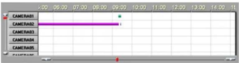
Timeline (zoom x2)
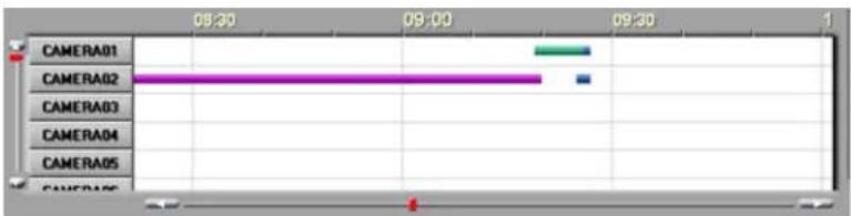
4.1.3. Camera Activation Buttons
Camera Activation buttons allow for a choice of specific cameras for each search. These buttons labels as configured in the Hardware Setup. To select a camera for a search, click the Came selected camera will be highlighted in blue.
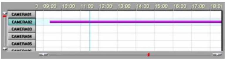
4.1.4. Camera Scroll Bar
Scroll up and down to see all the available Camera Activation buttons cameras
4.1.5. Timeline Marker
The vertical blue line is the Timeline marker that indicates the playback start time. In the ex- marker is set to 11AM.
4.1.6. Video Recording Bars and Types of Recording
Multicolored bars in the white video recording area represent different types of recording.
• the pink bar indicates Continuous Recording
• the blue bar indicates Motion Recording
• the green bar indicates Pre-alarm Recording
• the orange bar indicates Object / Sensor Recording
The timeline below indicates that the Camera 1 (Front Door) has recorded continuously from 52 (Parking) has recorded based on motion detection from 5:30 PM to 10:40 PM. Camera 3 based on Prealarm from 10 AM to 3:50 PM. Camera 4 (Warehouse) has recorded based on activity from 12:30 AM to 6:50 AM.
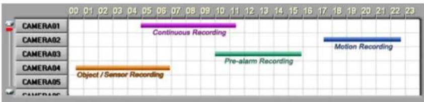
bar
| Method | Time (minutes) | |---|---| | CAMERA01 | 11 | | CAMERA02 | 23 | | CAMERA03 | 16 | | CAMERA04 | 1 | | CAMERA05 | 1 | | CameraA06 | 0 | Continuous Recording Pre-alarm Recording Object / Sensor Recording4.1.7. Playback Control Panel
Playback buttons are located on the bottom right corner of the Search Window.

Skip to the beginning of the recorded data
View previous frame
Reverse playback
Stop
Play
View next frame
Skip to the end of the recorded data
Real time - video is played back with the natural speed
Snapshot - takes the snapshot(s) during the video playback
Skip – the playback will skip several frames at a time. The higher the Skip value, the more frames will be skipped during the playback
Delay – will slow down the playback. The higher the Delay value, the slower the video recording will be played.
4.2. Tools Panel

The Tools panel contains the following function buttons:
Screen Division. Click the Screen Division button to switch between 4, 9, and 16 screen divisions. Depending on the amount of chosen cameras, the Search window will display the appropriate accommodate all chosen camera inputs. (e.g. if 5 cameras are chosen, a 9-camera screen
Panorama. Click the Panorama button to view the video segment frame-by-frame in the multiple screen division
Expand. Click the desired camera on the display screen during the playback and click the Expand button to enlarge the image to fit the display window
Zoom In / Zoom Out / Drag. Click the Zoom button to switch between the Zoom In, Zoom Out and Drag functions. The user can zoom in or out of a still image drag the enlarged image on the display screen.
Refresh. Click the Refresh button to refresh the timeline to display the recently recorded video.
Print. Click the Print button to print the still image on the connected printer.
Audio Setup. Click the Audio Setup button to mute/adjust the audio volume
Backup. Click the Backup button to save the video/still image on the local or remote media.
Bookmark. Click the Bookmark button to save the exact time of the video recording, so that it can be quickly located on the timeline later.
Full Screen. Click the Full Screen button to display a single camera, selected screen division or still image in the full screen mode with no Graphic User Interface (GUI)
4.3. Video Recording Playback
To playback the video recording in the Search mode, do the following:
- In the Time panel, choose the date from the Calendar window
- Set the time of the recording in the Time panel Clock window
OR
Set the time of the recording by clicking inside of the timeline bar to set the timeline to the start of the video recording to be played back.
- Choose one or more cameras in the Timeline bar by clicking on the appropriate camera activation buttons. If no cameras are chosen for the search, the following warning window will appear:


Note
Depending on the number of selected cameras, the video recording will be displayed in a 4, 9 or 16-camera screen division.5
- Adjust the Skip and Delay parameters on the Playback Control panel. The higher the Skip value, the more frames will be skipped during the playback. Increase the Delay value to slow down the playback.
To start the playback, click the Play button
- To view a single camera in a 1-camera division screen stop the playback, click the desi playback
- To go back to the multiple-cameras screen division: stop the playback, click on the display playback
4.4. Snapshot Function
The Snapshot function allows taking snapshots on a single or multiple cameras during the video improved feature allows taking instantaneous snapshots without pausing the video. The snapshots ta are automatically stored to the configured folder on a local or remote drive. To save the sna R/DVD-R, please use the Snapshot Backup feature.

Note
Please configure the default destination folder in the Snapshot Setup.
To use the Snapshot function, do the following:
- Select camera(s) for playback
- Set the start time in the Clock window or by clicking directly on the timeline
- To start the playback, click the Play button
- During the playback, click on the Snapshot button at the exact instance that needs to
The snapshots will be saved in the default destination folder. The snapshot name will start with "SSI" and will include the time stamp and the camera number. E.g. "SSI_20060104_094105_01.jpg"
The changes done to the video (zoom, sharpness, contrast, etc.) will NOT be reflected by 1
Related Topics: Server Information | Snapshot Setup | Snapshot Backup

Note
Please configure the snapshot format |JPEG / BMPI in Server Information setup
4.5. Panorama Function
The panorama function can be used to view the video recording frame-by-frame in the selected be done to see the motion progression, count the number of frames in a second, etc.
To use the Panorama function, do the following:
- Select a camera
- Set the start time in the Clock window or by clicking directly on the timeline
- Click the Panorama button on the Tools panel
- Select the desired screen division: 4, 9 or 16. (the number of frames to view on the c
- Adjust the Skip/Delay parameters in the Playback Control panel. Start playback by clicking the Play button
OR
Click the Next Frame button to display each consequent frame in the next screen division In the example below, Camera #1 is displayed on nine screens in the 9-screen division Panoram shows 9 consequent frames starting at 10:34:08 (frame#1) and ending at 10:34:08 (frame#9) on
| C01 2006/06/14-10:34:08-1 | C01 2006/06/14-10:34:08-2 | C01 2006/06/14-10:34:08-3 |
| C01 2006/06/14-10:34:08-4 | C01 2006/06/14-10:34:08-5 | C01 2006/06/14-10:34:08-6 |
| C01 2006/06/14-10:34:08-7 | C01 2006/06/14-10:34:08-8 | C01 2006/06/14-10:34:08-9 |
4.6. Image Zoom In/Zoom Out

Note
The instructions below apply to ings in the playback mode and images.
video record- paused still Select the camera
- Set the start time in the Clock window or by clicking directly on the timeline
- Start playback
- Click the desired camera to display it separately in the display window. For the still image, go to the step 5. To zoom into the video during the playback, go to the step 6.
- Stop the video recording by clicking the Stop button in the Playback Control panel
- On the Tools panel select the plus sign to zoom in or minus sign to zoom out To switch between zoom in/zoom out and drag buttons, click the Zoom button on the T
- Right-click on the video recording/still image to zoom in/out until the desired result is achieved. The video recording/image can be zoomed in digitally up to 17 times. Digital zoom refers to the pixelation of as optical zoom, which uses lens capacity to zoom in on a picture. Digital zoom changes affecting its resolution.
- To drag the enlarged image, choose the Drag button 🎨 on the Tools panel, click on the image, hold down the left mouse button and drag the image

Note
The existing bookmarks only exist as as the corresponding video recordings e on the hard drive. Once the video is overwritten, the bookmark no longer works.
4.7. Using Bookmark
Much like regular paper bookmarks, bookmarks in the Server Search mode are used to mark long video recording for quick access at a later time. The Bookmark function saves the date and instances in a single database, to simplify the search process later on.
To use the bookmark, do the following:
- Select the date of the recording in the Calendar window
- Set the start time in the Clock window or by clicking directly on the timeline
- Click the Bookmark button on the Tools panel
- Click Add. The set time and date will be automatically added the bookmark database.
- Enter the Bookmark description. E.g. below: Meeting, Closing Time, etc. Use the regular keyb keyboard provided by the ELMO DVR Server.
- To locate the bookmark on the time line, click Go To. The Time line marker will jump to the specified time on the Timeline Bar.
-
- To delete a bookmark, click on the bookmark in the list and click Delete
- To delete all bookmarks, click Delete All
- To close the Bookmark window, click OK

4.8. Advanced Search Panel
The Advanced Search panel allows Index and Object searching of the recorded video data.
Index Search


Object Search
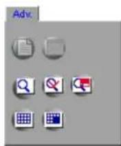
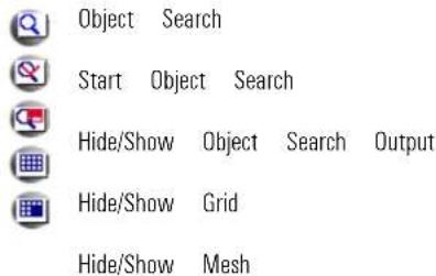
4.8.1. Index Search Panel
Click the Hide/Show Index Search panel button 📁 to bring up the Search Option panel.
The Index Search panel allows the users to distinguish between the different types of recording to the specific frames where detected motion, triggered sensors, or pre-alarm recording took place
The camera/sensor numbers that have recorded video data will be highlighted in yellow. The car recorded video data are grayed out. To select the recordings made with a camera/sensor to be bar, select the appropriate number on the Index Search panel. The selected camera/sensor buttons
The following information is known from the example below:

- Camera 1 has recorded video data
- Video data was recorded based on Pre-alarm, Motion and Sensors 2-4
Example 1,

In the example above,
The sensor video recording made with Sensors 2-4 is currently selected for display.
The following is know from this example:
- Camera 1 was recording based on sensor activity from 1:08 PM to 1:28 PM and from
Note: the following conditions had to be met for this sensor recording to
- Sensors 2-4 are activated in the Sensor Setup
- Camera 1 is associated with Sensors 2-4
- Recording schedule for Camera 1 is either O:S, M:S, O:S:P, or M:S:P
Example 2,

In the example above,
All types of video recording are currently selected for display.
The following is known from this example:
- Camera 1 was recording continuously until 12:37 PM. Schedule Setup setting: C
- Camera 1 was recording based on Motion from 12:38 PM to 12:55 PM. Schedule Setup s
- Camera 1 was recording based on Pre-alarm from 12:56 PM to 1:07 PM. Schedule Setup setting: M:P, O:S:P or M:S:P
- Camera 1 was recording based on Sensor from 1:08 PM to 1:28 PM and from 1:31 PM setting: O:S
4.8.2. Index Search

Note
This feature is NOT available on Remote.
Index Search allows for searching a recorded video according to recording type: motion or sensor. As opposed to the Index Search Panel, this function does not recognize Pre-alarm recording.
After clicking the Index Search button, the following panels will appear in the Search screenshot.
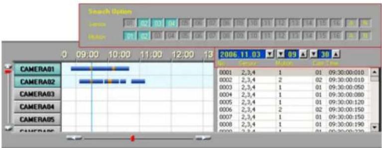
To search the available video recording based on Sensor or Motion, do the
- Select the day in the Calendar window
- Select the start time for Index Search. This can be done either from the Clock window or in the Index Search panel by scrolling the arrows up and down. In this example, the start time for Index Sea Index Search will search all available video recordings starting at the selected start time until day. An Index Search can only be performed within one calendar day.
- Select the Sensor number that triggered the motion recording (if applicable). Click A for "All" to select all sensors. Click N for "None" to deselect the chosen sensors.
- Select the camera, by number, that recorded based on Motion (if applicable). Click A for "All" to select all cameras for motion recordings. Click N for "None" to deselect chosen cameras.
- To view a specific frame, click on the desired frame in the list of found frames. The selected frame will be displayed in the Search display window.
Index Search displays the list of frames that meet the requirements Icamera number and type example, motion occurred on Cameras 1 and 2 starting 9:30 AM
The Search display window contains the following information:

- the frame number. E.g. No.0003
- the sensor number that triggered the video recording (if applicable) E.g. Sensor 2,3,4
- the camera number for motion recording (if applicable) E.g. Motion 1
- the camera number from which the video came E.g. Cam 01
- the exact time when the frame was recorded E.g. Time 09:30:00:080
The list will be updated instantly when the settings in the Search Option panel are changed. changed to 9:35 from 9:30, all frames recorded before 9:30 will be deleted from the list.
4.8.3. Object Search
The Object Search function is the smart search function that allows searching for a change in

To use the Object Search, do the following:
- Click the Object Search Button in the Advanced Search panel
- Choose the camera in the Timeline bar for an Object Search
- Select the Start Time and the End Time in the Clock window. Only the selected part of the video recording will be processed by the Object Search. An Object Search can only be performed within one calendar day


Note
An Object Search can only be one camera at a time.
performed
- Click the Grid button to remove the grid or to overlay the grid on the video image for easier area selection
- Click the Mesh button to remove the blue mesh or to highlight the selected search area
- Click the Object Search Output button to hide/display the separate Object Search window
- Highlight the area to be searched. Click on the screen. Hold the left mouse button down the desired area is covered. To remove the selection, hold the right mouse button and drag
- Click the Object Search Start button to start the Object Search
- Wait while the Object Search is processing the data
- When the Object Search is finished, one of the following message should appear:
a. No object motion was detected on the selected camera within the selected time period
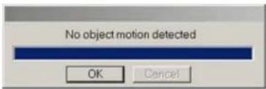
b. The Object Search has completed successfully
- In the Object Search Output window browse through the found instances.

Note
Make sure that the window with the is displayed. Otherwise, click the Object Search Output button.
The Object Search Output window can display results in either graphical or text format. In both cases, the object detection instance will have the time stamp displayed. To view the instance in the results on either the image thumbnail (example on the left) or the text line (example on the right
12.

![[10:08:56] Object Detect Object Search - Object Detection](/content/2026/05/941759/images/e1ce2ca4f15434f311780151ea9c7d8f47fe52e6ce581705712bf4e27de61612.jpg)
4.9. Image Settings Panel
The Image Settings panel is for editing still images. The edited image can then be printed on media.
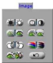
To enable the Image Settings panel, do the following:
-
Select the camera
-
Set the start time in the Clock window or by clicking directly on the timeline
- Start the playback
- Stop the playback at the exact frame
- Click the desired camera to show it separately in the display window. The Image Setting

Brightness. Click the right (left) icon to increase (decrease) image brightness.

Contrast. Click the right (left) icon to increase (decrease) image contrast.

Sharpness. Click the right (left) icon to increase (decrease) image sharpness.

Noise Reduction. Click the icon to reduce the noise in the image

Deskew. Images may sometimes be off-centered by a few degrees. The Deskew option is used to correct such skews. . Click the right (left) icon to rotate the image clockwise (counterclockwise

Gamma correction. Click the right (left) icon to decrease (increase) the gamma correction input. This is done in order to display the image colours correctly by customizing the gamma co output. The lower the gamma correction input the lighter the image.

Rotation. Click the icon to rotate the image clockwise by 90^ and to flip it vertically or horizontally.

Undo. Click the icon to undo all the changes and to return to the original image
Backup on ELMO DVR Server

Note
Any type of video backup made on the ELMO DVR Server and stored on any kind of removable media will be categorized as Removal Hdd Drive Data when played back on ELMO DVR Remote software.

Note
Please avoid using CD-R/DVD-RW/DVD-RW due to the lengthy formatting process.
Four types of Backup are available on the ELMO DVR Server:
Quick Backup - Configured in the ELMO DVR Server Search Window
Manual Backup - Configured in the ELMO DVR Server Search Window
-
Scheduled Backup - Configured in the ELMO DVR Server Setup menu
-
Panic/Sensor Backup - Configured in the ELMO DVR Server Setup menu
1. Quick CD Backup
Quick CD Backup allows quickly saving a portion of the video recording onto the CD-R/DVD-R AVI format.

Note
Quick CD backup is available on R/DVD-R only.
To perform a Quick Backup, do the following:
-
Ensure that there is enough free space on the C drive. CD-R/DVD:
-
Insert a CD-R/DVD-R/DVD-R into the combo drive.
-
Select one or more cameras
-
Set the start time in the Clock window or by clicking directly on the timeline
-
Right-click on the data area of the Search Bar: the context menu will appear. Select Mark Start to choose the start time.
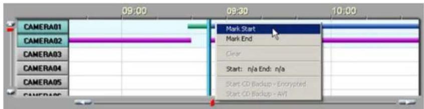
- Set the end time in the Clock window or by clicking directly on the timeline
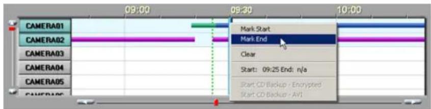
-
Right-click on the data area of the Search Bar. The context menu will appear. Select Mark End to choose the end time. Start Time on the Timeline has been marked with the broken green line
-
Right click and select Start CD backup – AVI to backup in AVI format. End Time on the Timeline has been marked with the broken red line; the segment of the recording between Start and End tim in blue.
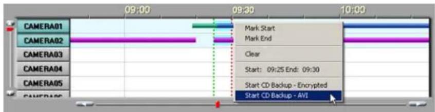
- To backup in encrypted format, select Start CD backup - Encrypted in the context

- To clear the Start and End times for quick backup, select Clear in the context menu.

- Wait for the backup process to complete. In the Backup window click Yes to burn the backup onto a CD-R/DVD-R immediately or No to burn later. (see Multi-CD Backup)

Related Topics: Multi-CD Backup
2. Manual Backup
Backup types:
- Snapshot (single frame / still image)
- Encrypted video can only be viewed with ELMO DVR Remote Software. One minute of the Encrypted video backup is always 66 megabytes.
- AVI (video can only be opened by AVI viewers). One minute of the AVI video backup can fluctuate between 1.3 megabytes and 2.5 megabytes depending on the recording settings.
- Email (a single frame or a 1 min. long video will be e-mailed as an attachment)

Note
Please avoid using CD-R/DVD-RW/DVD-RW for backup on the ELMO DVR Server, recording process is significantly longer compared to the CD-R/DVD-R/DVD-R. Backup on CD-R/DVD-RW/DVD-RW might slow down the ELMO DVR Server.
2.1. Snapshot Backup
![Backup Type Snapshot Encrypted AVI Email Data Time Start: Monday January 09.2006 10:41:00 End: Monday January 09.2006 10:42:00 Total Recording Time 1M Backup Media Drive : A: Select Media Browse Image Option: Priority: Low Camera Front Door Parking Back Door Warehouse CAMERA05 CAMERA06 CAMERA07 CAMERA08 CAMERA09 CAMERA10 CAMERA11 CAMERA12 CAMERA13 CAMERA14 CAMERA15 CAMERA16 All Select Compressor : Microsoft MPEG-4 Video Codes VZ. AVI Option: [Camera No] [Camera Name] [Date] [Time] Left Top OK Cancel](/content/2026/05/941759/images/20a1a3c32a00ead9066687b63ae3373f619e7ae84eb62bf8e6460b9c968d35b7.jpg)
Snapshot backup allows saving a single frame as a still image on any local drive in both *
To save a still image (Snapshot), do the following:
-
Stop the video playback on the exact frame
-
Click the desired camera to show it separately in the display window
-
Click the Backup button on the Tools panel
-
Choose Snapshot as the Type field
-
Click Select Media to choose the type of media to save the snapshot to
-
Choose the local or removable drive for the Snapshot backup. The snapshot file will be set of the selected drive.

- In the Watermark Checker Copy window, click Yes if this program has not been previously saved on the hard drive. Click No if it has been previously saved on the local drive before.
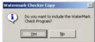
2.1.1. Browse Image
The Browse Image option allows browsing through the snapshots saved with the Snapshot feature via the main screen or the search window. The selected images can then be saved onto the local or remote RI.

To save a single/multiple snapshot(s) to the local/removable media, do the
-
Click Select Media to choose the type of media to save the snapshot to.
-
Choose the local or removable drive for the Snapshot backup. The snapshot file will be set of the selected drive.

-
Click on the '+' sign to expand the list of available cameras.
-
Select the desired camera from the list. Once the specific camera is selected, the system configured in the Snapshot Setup and displays the list of all available images in the middle all cameras, click Select All Cameras.
-
To preview, select the image from the list. In the example above, SSI_20060109_102345 is displayed in the Image Preview in the top right corner.
-
To copy the desired image to the configured media, select the image in the Available Image it to the Selected Image(s) list on the right. To select all images from the selected camera, click Select All Images.
-
To remove a single image from the Selected Image(s) list, select the image and drag-and-drop it to the Available Image(s) list in the middle. To remove all images, click Remove All Images.
- Check the Delete temporary Images checkbox in order to delete all selected images from the current folder.
- Click OK to proceed with the snapshot backup.
- All selected images will be saved into the Snapshot_Backup folder on the selected drive. Click OK to complete the snapshot backup.
Related Topics: Snapshot Setup
2.2. Encrypted Backup
Encrypted backup is a unique compression method, which records all available camera input in a
![Note If backing up to a remote drive, ELMO Remote Software has to be installed on the remote computer and the K-Remote Backup Server has to be running. Encrypted backup files can only be played in the ELMO DVR Remote Software. Backup Type Computer Encrypted AVI Email Date/Time Start Monday , August 15, 2005 14:12:00 End Monday , August 15, 2005 14:13:00 Total Recording Time Calculate Size Backup Media Selected Media Select Media Option Copy Remote Software to (D) Priority Low Camera CAMERA01 CAMERA02 CAMERA03 CAMERA04 CAMERA05 CAMERA06 CAMERA07 CAMERA08 CAMERA08 CAMERA10 CAMERA11 CAMERA12 CAMERA13 CAMERA14 CAMERA15 CAMERA16 Note: You can backup selected camera(s) only on CD. Select Compression: Molcowr MPEG-4 Video Codes V2 AVI Caption: [Camera No | [Camera Name] [Date] [Time] Left: Top OK Cancel](/content/2026/05/941759/images/86ab6a71eedfcd49d454d46c746fe53953f0ded2cefefe955401f13b5136ce06.jpg)
To perform the Encrypted Backup, do the following:
-
Click the Backup button on the Tools pane
-
Choose Encrypted in the Type field
-
Set the Start date and time from the Start menu
-
Set the End date and time from the End menu
Make sure there is recorded video data in the selected time period. Otherwise, the warning and the backup will not be performed.
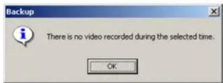

-
Click Calculate Size to estimate the size of the encrypted backup file.
-
Select the desired cameras for backup in the Camera field. By default, all cameras are selected for backup. If specific cameras are chosen, the backup must be performed to a CD-R/DVD-R.
-
Click Select Media to choose the destination for the encrypted backup. The Encrypted backup file can be saved to the local or a remote drive.
ELMO DVR _B . Saving to the local drive. The recording will be saved to the LocalDrive:\kdb\backup
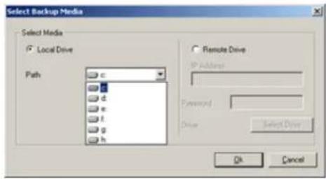
i. Select Local Drive to save the encrypted video recording to any local drive
ii. Click the drop-down menu in the Path field
iii. Select the desired drive
iv. Click Ok
b. Saving to the remote drive. The recording will be saved to the RemoteDrive:\kdb\t

Note
All video recordings saved to the remote drive will be displayed under the Backup Data category in the ELMO DVR Remote local Search mode.

i. Select Remote Drive to save the encrypted video recording to a remote drive
ii. Enter the IP Address of the remote computer
iii. Enter the password to access remote computer

Note
The ELMO DVR Remote Software has to be installed and the K-Remote Backup Server has to be running on the remote computer, otherwise the connection will not be established.
iv. Click Select Drive. The Drive Select window will appear.

v. Choose the remote drive from the Drive Path (drop-down menu) once the connection has been established
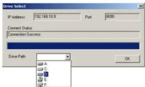
vi. Click OK
vii. Click OK in the Select Backup Media window to close it
- Check the Copy Remote Software to CD checkbox if backing up to a CD-R/DVD-RC ELMO DVR Remote software along with the backup files
- Set the priority of this backup process (High/Low). If set to High, this backup will have priority over other backup processes (e.g. scheduled backup).
s inClick OK to start the backup process.
- The backup progress window and the rising icon on the top of the screen will be dis the backup process.
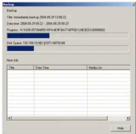
- If saving onto a CD-R/DVD-R, wait for the backup to complete. In the Backup window click Yes to burn the backup onto a CD-R/DVD-R immediately or No to burn later. (see Multi-CD Backup)
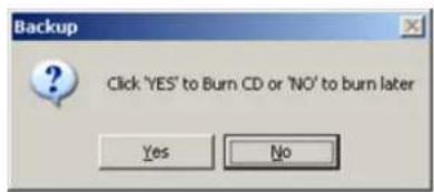
Related Topics: Multi-CD Backup
2.3. AVI Backup
AVI Backup can be performed to both Local and Remote drives (folders).

Note
If backing up to a remote drive, ELMO Remote Software has to be installed on remote computer and the K-Remote Backup Server has to be running. Video recording from each camera input is saved as a ate file with an *.avi extension. AVI ba files can only be opened with the AVI viewers i.e. Window Media Player, Quick Time, Real Player, etc.I
![Backup Type Snapshot Encrypted AVI Email the Date/Time Start Monday, August 15, 2005 Separ- 09:57:00 End Monday, August 15, 2005 09:58:00 Total Recording Time 1M Backup Media Selected Media Select Media Option Priority Low Camera CAMERA01 CAMERA02 CAMERA03 CAMERA04 CAMERA05 CAMERA06 CAMERA07 CAMERA08 CAMERA09 CAMERA10 CAMERA11 CAMERA12 CAMERA13 CAMERA14 CAMERA15 CAMERA16 All Select Compressor : Microsoft MPEG-4 Video Codec V2 AVI Caption : [Camera No.] [Camera Name] [Date] [Time] Left, Top OK Cancel](/content/2026/05/941759/images/3373ccbfcdcb91ae9486bfa2b9f8afc9b05d64beb94d29ba87d4926ffaf68697.jpg)
To perform the AVI Backup, do the following:
1.
Click the
Backup

on the
Tools
panel
- Choose
AVI
in the
Type
field
- Set
Start
date
and time
from
the St
rt me
- Set
End
date
and
time
rom
the
End
menu
Make sure there is recorded video data in the selected time period. Otherwise, the warning and the backup will not be performed.

- The Total Recording Time will be displayed in the drop-down menu. When backing up lengthy video recordings, this menu will have 5, 10 and 30 minute, and 1 hour backup options that can be chosen recording time.

Note
The size of the AVI backup file on the video recording settings. a one-minute AVI video recording ate between 1.3MB and 2.5MB.
- Select the desired camera for backup in the Camera field
The size 7. of Click Select Media to choose the destination for the AVI backup. The AVI backup file can be saved to a local or fluctuate remote drive.
a. Saving to the local drive.

i. Select Local Drive to save the AVI video recording to any local drive
ii. Enter the descriptive File Name for the AVI backup file
iii. Click the Browse button to select the local drive and folder for the AVI backup
iv. Browse through the local drives and select the desired folder

Note
If no custom folder is selected, AVI file will be saved to the rive::kdb|BACKUP_AVI folder.
the backup LocalD-
v. Click Ok
Saving to the remote drive. The recording will be saved to the RemoteDrive:\kdb\BACKUP_AVI folder

Note
All video recordings saved to the remote drive will be displayed under Backup Data category in the ELMO DVR Remote local Search mode.

i. Select Remote Drive to save the AVI video recording to a remote drive
ii. Enter the IP Address of the remote computer

Note
The ELMO DVR Remote Software installed on the remote computer K Remote Backup Server has to otherwise the connection will not lished
has to be and the be running, be estab-
iii. Enter password to access the remote computer
iv. Click Select Drive. The Drive Select window will appear.

v. Choose the remote drive from the Drive Path drop-down menu once the connection has been established

vi. Click OK
vii. Click OK in the Select Backup Media window to close it.
-
Set the Priority of this backup process (High/Low). If set to High, this backup will have priority over other backup processes (e.g. scheduled backup).
-
Select all desired cameras from Camera list. Only the video recordings from selected cameras server will create backup files with the custom file name and the camera number for each Time [1].avi; Closing Time [5].avi. In this example, 2 AVI backup files were created: for ca
-
Select the video codec for the AVI backup from the Select Compressor field. Select the codec name displayed for the list of all available codecs.

Attention: It is highly advisable to leave the default codec chosen by the Server - it is always the latest available codec. (In this example, Microsoft MPEG-4 Video Codec V2) The only reason to change the is to play back the AVI backup file on the older system with older codecs installed.
- Select the desired AVI Caption format for the AVI file. Select the default caption format for the list of all available caption formats. The AVI Caption text will be overlaid on the AVI video recording. Select Disable for no caption text overlay.
![Disable ✓ [Camera No.][Camera Name][Date][Time] [Camera No.][Date][Time] [Camera Name][Date][Time] [Camera No.] [Camera Name]](/content/2026/05/941759/images/8b0c0c84123e9b76af6a820121c3474fa577f7479dd232528091808da8441ee3.jpg)
- Select the position for the AVI caption from the list. The Caption position determines the position of the Caption text overlay on the AVI video recording. Select the default caption position (Left, Top) for the list of all available caption positions.

- Click OK to start the backup process.
The backup progress window and the recording icon on the top of the screen will be dis the backup process.
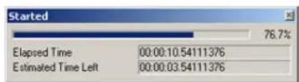
- If saving onto a CD-R/DVD-R, wait for the backup to complete. In the Backup window click Yes to burn the backup onto a CD-R/DVD-R immediately or No to burn later. (see Multi-CD Backup)
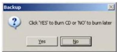
Related Topics: Multi-CD Backup
2.4. Email Backup
E-mail backup allows the user to send a Snapshot or an AVI video file from a single came one or multiple recipients. Due to the fact that many mailing providers do not allow large e-mail attachments, the length of video recording for AVI attachments is automatically limited to 1 minute.
2.4.1. Emailing a Snapshot
![Backup Type Snapshot Encrypted AVI Email Date/Time Start Thursday : November 02.2006 11:31:00 End Thursday : November 02.2006 11:32:00 Still Image backup AVI backup Mail Setting Recipients List user@provider.com Add DEL Outgoing Mail sntp.askuprovider.com Sender's Email uremail@provider.com Mail Subject Snapshot Camera CAMERA01 CAMERA02 CAMERA03 CAMERA04 CAMERA05 CAMERA06 Camera07 CAMERA08 CAMERA09 CAMERA10 CAMERA11 CAMERA12 CAMERA13 Camera14 Camera15 Camera16 AI Select Complete Microsoft MPEG-4 Video Codes V2 AVI Caption [Camera No] [Camera Name] [Date] [Time] Left, Top OK Cancel](/content/2026/05/941759/images/c4a04a6a865d0ebefe2c66c2ff9eae5864441a0d02e24d3ecb9874589191c578.jpg)
In order to email a snapshot, do the following:
- Stop the video playback on the exact frame
- Click the desired camera to show it separately in the display window
- Click the Backup button on the Tools panel
- Choose Email in the Type field
- Choose Still Image backup
- Add recipients e-mail addresses to the Recipients List. The still image/AVI video will be sent to all recipients on the list
a.

b. Type in the Recipient's e-mail address
c. Click Save/Exit to add the e-mail to the list
d. Click Close to exit without adding the e-mail
e.
To delete an e-mail, click on it in the Recipients List and click DEL
- Enter the simple mail transfer protocol |SMTP| in the Outgoing Mail field. In this example, smtp.bellnexxia.net.
Obtain this information from the e-mail provider.
-
Enter Sender's Email
-
Enter Mail Subject
-
Click OK to send the e-mail
2.4.2. Emailing an AVI Video
![Backup Type Snapshot Encrypted AVI Email Date/Time Start Thursday . November 02. 2006 11:31:00 End Thursday . November 02. 2006 11:32:00 Still Image backup AVI backup Mail Setting Recipients List user@provider.com Add DEL Outgoing Mail sntp.askuprovider.com Sender's Email uremail@provider.com Mail Subject Snapshot Camera CAMERA01 CAMERA02 CAMERA03 CAMERA04 CAMERA05 CAMERA06 CAMERA07 CAMERA08 CAMERA09 CAMERA10 CAMERA11 CAMERA12 CAMERA13 CAMERA14 CAMERA15 CAMERA16 Select Compressor: Microsoft MPEG-4 Video Codec V2 [Camera No] [Camera Name] [Date] [Time] Left, Top OK Cancel](/content/2026/05/941759/images/316ebcdb5f478ef01ae399cb64ca8aeb67babfe5a04ac38271df51748c7bac5a.jpg)

Note
The size of the AVI backup file on the video recording settings. of one-minute AVI video recording tuate between 1.3MB and 2.5MB. this fact before sending an AVI
In order to email an AVI video file, do the following:
e will depend The size ^1 .a Click the Backup button on the Tools panel can lluc- Consider video file. 2 Choose Email in the Type field
-
Choose AVI backup
-
Select the desired single camera from the Camera list
-
Select the video codec for the AVI backup from the Select Compressor field. Select the codec name displayed for the list of all available codecs.

Attention: It is highly advisable to leave the default codec chosen by the Server - it is always the latest available codec. (In this example, Microsoft MPEG-4 Video Codec V2) The only reason to change the is to play back the AVI backup file on the older system with older codecs installed.
- Select the desired AVI Caption format for the AVI file. Select the default caption format for the list of all available caption formats. The AVI Caption text will be overlaid on the AVI video recording. Select Disable for no caption text overlay.
![Disable ✓ [Camera No.] [Camera Name] [Date] [Time] [Camera No.] [Date] [Time] [Camera Name] [Date] [Time] [Camera No.] [Camera Name]](/content/2026/05/941759/images/ac2ff8a9fb7eb560979fd5f82ab190be280a026746d9a21ac30cd98c9b073d15.jpg)
- Select the position for the AVI caption from the list. The Caption position determines the position of the Caption text overlay on the AVI video recording. Select the default caption position (Left, Top) for the list of all available caption positions.

- Add recipients e-mail addresses to the Recipients List. The still image/AVI video will be sent to all recipients on the list.
a.
b. Type in the Recipient's e-mail address
c. Click Save/Exit to add the e-mail to the list
d. Click Close to exit without adding the e-mail
e. To delete an e-mail, click on it in the Recipients List and click DEL
-
Enter the simple mail transfer protocol (SMTP) in the Outgoing Mail field. In this example, smtp.bellnexxia.net. Obtain this information from the e-mail provider.
-
Enter Sender's Email
-
Enter Mail Subject
-
Click OK to send the e-mail
3. Multi-CD Backup
Multi-CD Backup feature works for both AVI and Encrypted backups. It can be performed either through Quick Backup or Manual Backup in the Search mode. Multi-CD Backup allows temporary saving the Encrypted/AVI backup files onto a hard drive in order to burn several backup processes onto a single CD-R/DVD-R at a later time without accessing the Desktop.

Note
If backing up through Manual Backup, CD drive must be chosen as the Backup Media in order to use Multi-CD Backup function2.
To perform the Multi-CD Backup, do the following:
Click Search
Complete Quick Backup - Encrypted or AVI
OR
Complete Manual Backup - Encrypted or AVI. Make sure to choose CD-R/DVD-R as a Backup
- Start Backup, wait for the following window:

-
Click No to temporary save the current backup onto the hard drive.
-
The following Multi-CD buttons will appear in the Search Window:

The Del. Backup button allows deleting all backup processes temporary saved onto the hard drive.
The Burn CD button allows burning all backup processes temporary saved onto the hard drive onto a single CD-R/DVD-R.
The same Multi-CD buttons will be displayed on the Main Screen outside of the Search Mode

Note
Total size of the temporary backups should not exceed the size of the CD-R/DVD R.

Note
The temporary Multi-CD backups are not deleted from the hard drive when system is restarted, they remain on the hard drive until either deleted or burned onto a CD-R/DVD-R.
ELMO DVR Remote
The ELMO DVR Remote software is used to connect to and manage multiple servers by using connection. The managers can easily view the cameras in the remote location, search the record the PACDM™ database from the comfort of their home. Most of the features provided in ELM in ELMO DVR Remote, though these software products are not identical. Unlike the ELMO DVR can easily be turned off without shutting down the system or can be minimized like any other level of access assigned to the user in the ELMO DVR Server remains the same when loggir E.g. If the user is restricted from viewing Camera 1, they will not be able to see it via in with their name and password.
1. Starting ELMO DVR Remote
The ELMO DVR Remote software is used to connect to and manage multiple servers by using connection. The managers can easily view the cameras in the remote location, search the record the PACDM™ database from the comfort of their home. Most of the features provided in ELM in ELMO DVR Remote, though these software products are not identical. Unlike the ELMO DVR can easily be turned off without shutting down the system or can be minimized like any other level of access assigned to the user in the ELMO DVR Server remains the same when loggir E.g. If the user is restricted from viewing Camera 1, they will not be able to see it via in with their name and password.
Before connecting to a remote site, please ensure the following:
- The following minimum hardware specifications are met (PIII 500 MHz; 128MB RAM; 64MB Windows 2000/XP)
- The same versions of ELMO DVR Server and ELMO DVR Remote are used.
- The remote ELMO DVR Server is on. The correct type of connection and Live Video Strea Communication Setup.
- The correct type of connection is set in ELMO DVR Remote - Communication Setup.

Note
If connecting to ELMO DVR Server v.5,01 remotely, the video image will appear narrower than the screen division resulting in two vertical black stripes on either side of the time. Please note that this is caused by higher resolution and is normal.
1.1. Logging In
To open the ELMO DVR Remote software, do the following:
1.
Click the ELMO DVR Remote icon or ELMO Rem Desktop
- When logging in for the first time, enter elmo as the password. Click OK to log in.

- To change the password for ELMO DVR Remote, do the following:

a. Click Change Password
b. Enter old password
c. Enter new password
d. Re-enter new password to confirm it
e. Click OK to save the new password
When the ELMO DVR Remote software is started, the following screen will appear:

1.2. Creating New Remote Site Connection
To create a new Server connection, do the following:
1.
Click Connections on the main screen
- Click on the "Server" group
- In the Server Connect - LAN window, click Add
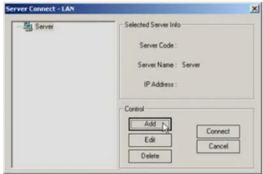
- The Insert to new site window will appear

- Choose the group to which the new connection will be established
a. Choose the existing group from the drop-down menu
b. To add a new group, click Add Group and Enter the name of the new group. Click Ok.

-
Enter Server ID - a maximum of 7 alphanumeric characters. This must match the remote Server ID as entered in the Server Information Setup.
-
Enter a Server Name - a descriptive name for the server. E.g. "boston"
-
Enter the Server IP Address. This must match the remote Server IP Address. Unless the ELMO DVR Server has a static IP Address or a Dynamic IP domain service, the remote connection will not

If the remote site is currently in the Setup mode, the connection will not be established message will be displayed.

-
Check the Connect when system starts checkbox to connect to the site automatically every time the ELMO DVR Remote software loads.
-
Enter the User Name and User Password. When trying to connect to the remote server, the system will check the Server ID, User Name and User Password together. If either of the variables is incorrect, the Remote software will not be able to connect to the site.
-
Check the Emergency Alarm checkbox to use the custom alarm each time the alarm occurs on the remote site
-
Choose the *.wav file for the custom alarm in the Sound File field. Click Browse to locate the *.wav sound file that will play every time that the alarm is triggered on the remote site.
-
Configure the Duration of Sound Wave for the custom alarm: 1-99 sec.
-
Click OK to save the new connection, or click Cancel to close the new site setup window without saving
-
To delete an individual site, choose it in the Connections list, and click Delete
-
To delete the entire group, choose the group from the list and click Delete. Click Yes in the window below to delete the group. Click No to delete the group but not the remote sites. If No is clicked, the group will be deleted from the list and all sites from the group will be added to the first remaining group.
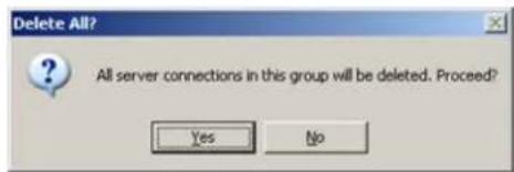
- When information for the new site is completed, it will appear in green font in the Server Info window on the main screen. In this example there are currently 2 configured remote sites, both are currently
1.3. Main Screen
The areas of the ELMO DVR Remote main screen are:
- About
- Date and Time
- Exit
- Help
11.View/Stop - Sensor/Control panel
- Emergency Monitor
- Search
- Camera panel
- Health Monitor
- Setup
- Screen Division
- Intelli-Upgrader
- Connections
- Full Screen
- K-Remote Backup Server
- Disconnect
- Multi-Site Selection Tool
- 2-Way Audio
- Multi-Site
- Multi-Site Display
- Minimize
- Server Info
- Close
- RECEIVE

About
About - Displays the ELMO USA CORP. license Agreement and the version of the ELMO DVR Remote software installed on the ELMO DVR. To close, click I Accept in the bottom of the license agreement.
Help
Help - Displays the help menu window. The major help topics are available.
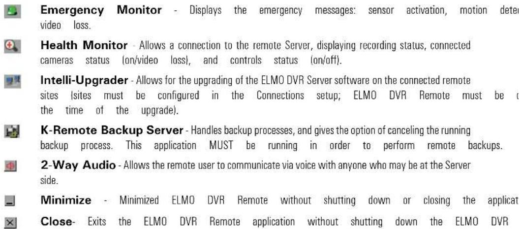

Date and Time - displays the current time and date. This information is Windows OS time and date settings. If time/date is not correct, minimize/close the application and double-click the Windows time display in the right-hand corner. Set time and click Apply. The time will be automatically updated in the ELMO [

View/Stop - connect to the remote server, select desired cameras in the Ca click View to display the selected cameras. Click Stop to stop transmitting live video from the remote server.

Search - In local mode, the Search button gives access to video recordings stored on the local or removable drive. When connected to the remote server, the Search to the video database of the remote server.

Setup - In local mode, the Setup button gives access to the ELMO DVR Remote software setup menu. When connected to the remote server, the Setup button gives access to DVR Server software setup menu.


Connections - Manages the lists of the remote server connections.
Disconnect - Breaks the connection with the connected remote server(s).
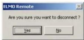

Multi-Site - Displays the window with all available cameras on all connected from different connected servers can be displayed on the same Screen Division. through drag-and-drop.
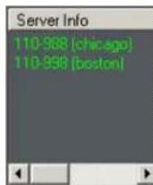
Server Info - Displays the connection status of all configured remote sites (online/offline). The connected sites are highlighted in red, the sites that are offline, are highlighted in green. In this example, ELMO DVR Remote software is connected to two remote sites; the rel are currently offline. To connect to the remote site, double-click the desired rem Server Info window.
RECEIVE - Displays the progress of data transmission
Power - Exits the ELMO DVR Remote application without shutting down the ELMO

Sensor and Control panel

The Control panel activates the selected controls on the connected remote site. The Sensor panel status on the connected remote site
Camera panel
The Camera panel allows choosing the cameras to be displayed in the ELMO DVR Remote max camera numbers and click View. To display all the available cameras, click All. The camera numbers that are currently displayed are highlighted in blue. In this example, cameras 1-4 are presently displayed in the r

Screen Division - this panel allows customizing the main screen appearance. By clicking on the Screen Division buttons, ELMO DVR Remote will select the corresponding amount of cameras for viewing. Three are available on ELMO DVR Remote: 4, 9 and 16-cameras screen divisions.

Selects and displays the first 4 available cameras on the Main Display Screen screen division

Selects and displays the first 9 available cameras on Main Display Screen in division

Selects and displays the first 16 available cameras on Main Display Screen in a 16 cameras screen division

Full Screen - This button displays a single camera or chosen screen division bars (no interface shown). Right-click to exit the full-screen mode.

Multi-Site Display, Multi-Site Selection Tool - Scroll the arrows up and down to switch between connected sites. and Server ID of the currently active connection are displayed site display window.
1.4. Connecting to the Remote Site
Before connecting to a remote site, ensure that the remote ELMO DVR Server is on. The same versions of ELMO DVR Server and ELMO DVR Remote must be used.
It is possible to connect to multiple remote sites at the same time.
There are two ways to connect to the remote site from the ELMO DVI software.
1. Main Screen
In the Server Info window, double-click the desired server.
2. Connections menu
a.
Click Connections on the ELMO DVR Remote main screen
b. Click the (+) sign next to the group and choose the desired connection
c. Click Connect

d. The following window will appear to indicate that the ELMO DVR Remote software is remote Server
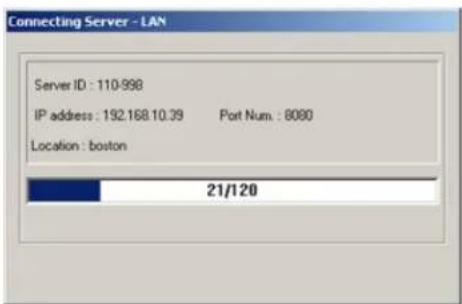
- The Server Info window provides the connection status for the configured remote sites. The sites currently connected are highlighted in red, the sites that are currently disconnected are highlighted in
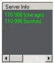

1.5. Viewing the cameras on the connecte remote site
To view the real-time video on the remote site, do the following:
- Connect to the desired remote site(s) (See the Connecting to a Server section for step-by-step instructions)
- Select the cameras for viewing in the Camera panel. Click All to view all cameras available on the remote site.
3.

If no cameras were selected in the Camera panel, the following warning window will appear


Note
Depending on the number of selected eras, the video will be displayed in 16-camera screen division.
- Click the desired camera on the main screen to display it in a 1-camera screen division. Left-click again to go back to the multiple cameras screen division.
4, 9 or 5. To add additional cameras for display, click Stop, select additional cameras in the Camera panel and click View
- To add additional cameras or remove specific cameras from the Screen Division without stop click Multi-Site. The Multi-Site window with the connected server name(s) will be displayed on the right-hand panel of the main screen window.

a. Double-click on the server name to display the list of available camera la rently displayed are highlighted in red, cameras currently offline are highlighte b. To add a specific camera to the main screen display, click the camera mouse button down and drag the selected camera onto the main screen. c. To stop viewing the specific camera, right-click the camera label in the Mu d. Click Exit to close the Multi-Site window
-
To stop viewing all cameras without disconnecting from the remote site, click Stop
-
To switch between multiple connected sites, scroll the arrows up and down in the Multi-Site Selection Tool

1.6. Using Multi-Site tool
The Multi-Site tool allows for the viewing of cameras from multiple remote sites in the same
To use the Multi-Site tool, do the following:
-
Connected to at least two remote sites
-
Click Multi-Site on the Control panel
-
The list of the connected server name(s) will be displayed on the right-hand panel of the
-
Double-click each server's name to display the list of all available cameras. Cameras currently displayed are highlighted in red, cameras currently offline are highlighted in orange.
-
Click the desired camera name (label) in the Multi-Site window, hold the left mouse button down and drag the camera name onto the main screen. The camera will be displayed in the chosen screen div
-
To remove a camera from the Screen Division (to stop viewing this camera), right-click the the Multi-Site window
-
Click Exit, to close Multi-Site window
1.7. Disconnecting from the Remote Site
To disconnect from the remote site(s), do the following:
- Select the desired remote site in the Multi-Site selection tool by scrolling the arrows up a

2.
Click Stop to discontinue video transmission from the remote site
3.
Click Disconnect
- Click Yes in the warning window. The connection with the remote site will be broken and the remote site name will be highlighted in green in the Server Info window.


Note
If the user on the ELMO DVR Server side opens the Server Setup, the remote connection is terminated.

2. Configuring ELMO DVR Remote
ELMO DVR Remote Setup is only available in the Local mode. To access Local Setup, disconned and click Setup on main screen.
2.1. About ELMO DVR Remote

The About setup tab provides information about the system:
- List of drives/partitions
- Total and free hard drive space information
- Processor type
- RAM size
- Windows operating system version
- Service Pack version
- ELMO DVR Remote software version
2.2. Configuration Setup
In the Configuration Setup, the user can setup the Automatic Backup, configure the Watermark screen display settings.

To setup the Configuration Setup, do the following:
- Check the Display Sensor Status Bar checkbox to display the Sensor panel on the main screen when connected to the Remote site.
- Check the Display Control Status Bar checkbox to display the Control panel on the main screen when connected to the Remote site.
- Check the Display WATERMARK logo checkbox to display the watermark logo in green font on all watermarked video recordings during the playback.
- Check the Start with Password checkbox to request password on each startup
- Configure the Automatic Backup in the Received Data Save Setup menu:
a. Check the Current Screen Data Save checkbox to save the live video recordings on the selected local drive, as they are viewed in the ELMO DVR Remote software.
b. Check the Current Screen Data Save checkbox to save the live video recordings on the selected local drive, as they are viewed in the ELMO DVR Remote software.
c. Choose the local drive in the Select Save Drive drop-down menu. The data from the Automatic Backup will be saved to this local drive.
- In the Display Mode menu choose between DirectX and RGB display modes. If the video card meets the minimum hardware requirement of 64MB, select DirectX. If the video card does not meet the minimum hardware requirement, select RGB.
- Select the server sort order from Ascending, Descending, or None in the Sort Server Info by Alphabetic Order menu
Check the Play Sound with unknown server checkbox to use the custom alarm w do not have a custom alarm assigned to them
- Choose the *.wav file for the custom alarm in the Emergency Alarm field. Click Browse button to locate the *.wav file that will play every time alarm is triggered on the remote site.

Note
ELMO USA CORP. does not guarantee proper functioning of ELMO Remote if the system does not meet minimum hardware 8 requirements.
- Configure the Duration of Sound Wave for the custom alarm: 1-99 secs
2.3. Communication Setup

In Communication Setup, configure the type of connection available on the system.
- Select PSTN (modem) / ISDN - No Router for modem connection.
a. Enter Installed modem name
b. Enter Initialization string
c. Enter Port number and modem transfer speed |Bps|
OR
Select LAN/ISDN - Router / Leased Circuit for other Internet connections.
- Click OK to save the settings
2.4. Other Setup
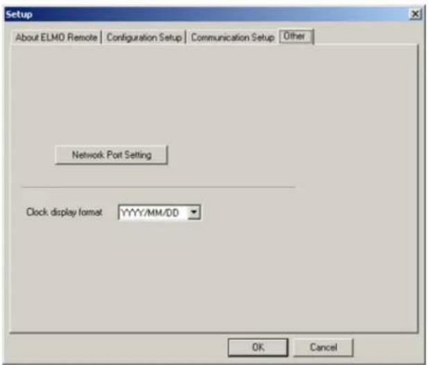
To view/change port settings, do the following:
- Click Network Port Setting
![Network Port Setting MainControl Port 8080 MainVideo Port 8081 IntelliUpgrade Port 8083 HealthMonitor Port 8084 EmergencyMonitor Port 8085 Center Backup-Server Port 8090 Two-Way Audio[cmd] Port 3001 Two-Way Audio[Audio] Port 3005 EmergencyConnect Port 6911 OK Cancel](/content/2026/05/941759/images/6b7cc03a0258c85456fd211fa1fdd762d91d933127de86688d614e88398cd798.jpg)
-
Change the settings if needed
-
Click OK to save the changes.
OR
Click Cancel to exit without saving
To change the time and date display, click the Clock display format drop-down menu. The current time and date in the ELMO DVR Remote main screen will be displayed according to the format chosen here.
3. Search on ELMO DVR Remote
ELMO DVR Remote software allows searching video recordings stored on the remote site and vi locally.
3.1. Local Backup Search Categories
When searching the remote backup files saved locally, ELMO DVR Remote distinguishes between t files based on the type of the backup that they were saved with.
The search Mode Select window distinguishes the following backup search categories:
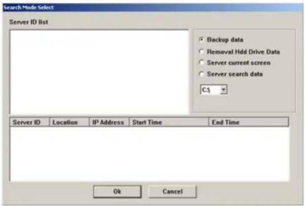
- Backup data
- Removal Hdd Drive Data
- Server current screen
- Server search data
Backup Data
This backup category includes all the encrypted backups done through the ELMO DVR Remote, saved remotely to the ELMO DVR Remote from ELMO DVR Server software.
E.g. ELMO DVR Server software is installed on the ELMO DVR at a business's premises. ELMO installed in the manager's office. All the encrypted backups made from the ELMO DVR in the store to the manager's computer AND all the encrypted backups made on the manager's computer, while remotely connect Server in the store, will show up under the Backup Data category.
Removal HDD Drive Data
This backup category includes all the encrypted backup files stored on a hard drive that has ginal ELMO DVR and connected to the system, where ELMO DVR Remote software is installed.
Server Current Screen
This backup category includes the automatic backup files of the video recordings viewed remotely, the remote site. All the backup files made with the "Current Screen Data Save" will be saved under this backup category.
Server Search Data
This backup category includes the automatic backup files of the video recordings searched remotely the remote site. All the backup files made with the "Remote Search Data Save" will be saved under this backup category.
3.2. Local Search on ELMO DVR Remote
To search video recordings stored locally, do the following:
- Disconnect from all connected servers
2.
Click Search on the
- In the Search Mode, choose the backup type
- Choose the local drive where the backup information has been stored
- In the Server ID list select the appropriate backup file. The backup files are additionally sorted by the remote Server ID from which they have been recorded.
- Click Ok. The local Search window will appear.
3.3. Search Window in the Local mode
The areas of the Search Window are:
- 2-Way Audio
- Minimize the Window
- Time panel
- Playback Control panel
- Skip
- Delay
- Camera Selection panel
- Backup
- Adjust Video Brightness
- Zoom In/Out
-
Exit
-
Full Screen
-
Audio Settings
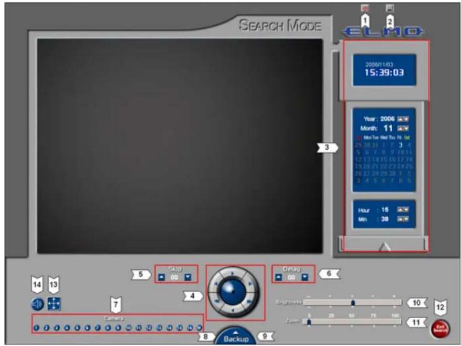
2-Way Audio - Allows the remote user to communicate via voice with anyone who may be at the Server side.
Minimize - Minimize ELMO DVR Remote without shutting down or closing the application.
Time Panel
The Time panel is identical to that of the ELMO DVR Server Search window. (See the Search on ELMO DVR Server section for more information) Days, highlighted in red, signify that there is a corresponding video recording stored on the local hard drive. In this example, there is backup video information for October 1st and 3rd, 2004.
Playback control panel.
Except for the graphic aspect, the Playback panel is identical to the Playback panel in ELMO (See the Search on ELMO DVR Server for more information)
Skip & Delay - Same as in ELMO DVR Server Search window. (See the Search on ELMO DVR Server section for more information)
Camera Selection Panel.
The Camera Selection panel allows for a choice of specific cameras for playback. Click All to view all cameras.
Backup panel: (Click Backup to expand)
Backup - is identical to the Manual Remote Backup (See the Manual Backup section for more information).
Print - This button is for printing the still images with the local network printer
Adjust Brightness - Allows adjustments to the video brightness
Zoom In/Out - Is for zooming in and out of the video recording
Exit - Is for exiting the Local Search mode
Full Screen - Is for entering the full-screen mode - no Graphic User Interface
Audio Settings - Is for enabling the audio playback on specific camera and adjusting the volume (High/Low)
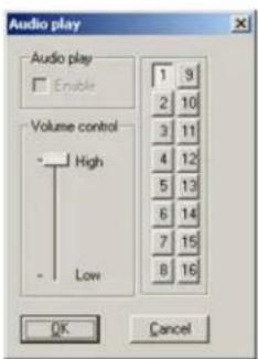
To perform a Search in the Local Search window, do the following:
-
Select the Date in the Calendar Window
-
Select the Time in the Clock Window
-
Select the cameras to be searched in the Camera panel
-
Adjust the Skip and Delay values
-
Click Play on the Playback Control panel

Note
Advanced search options, image editing and access to PACDM™ are not available in the ELMO DVR Remote Local Search window.
3.4. Searching a Connected Remote Site
One of the main functions of ELMO DVR Remote software is searching the video recordings st ELMO DVR Remote software must be connected to a remote site before a remote search can
To search a remote site, do the following:
- Connect to a desired remote site.
2.
Click Search on the main screen. The Search window will appear.
Please note The remote search window on ELMO DVR Remote is identical to the search window on the ELMO DVR Server with the following exceptions:
-
The Search window on ELMO DVR Remote allows switching between multiple connected remot the Multi Site selection tool.
-
The Search window on ELMO DVR Remote allows switching between multiple connected remot the Multi Site selection tool.
- 2-Way Audio connection can be initiated through the ELMO DVR Remote Search window
- No Advanced Search panel is available in the ELMO DVR Remote Search window
- No Quick CD Backup is available in the ELMO DVR Remote Search window
Backup on ELMO DVR Remote
Two types of backup are available on ELMO DVR Remote: Automatic Backup and Manual Backu
- Automatic Backup
- Manual Backup
1. Automatic Backup
ELMO DVR Remote software can be configured to save the video recordings viewed or searched media automatically. Automatic backup is configured in the ELMO DVR Remote local Configuration Setup. (Please refer to the ELMO DVR Remote Local Setup - Configuration Setup)
Automatic Backup of the video recordings viewed remotely:
The user has an option of automatically saving all the video recordings that are viewed remote. To automatically save all remotely viewed video recordings onto the local drive, check "Current Screen
Data Save" option in the ELMO DVR Remote Configuration Setup. Choose the local drive to which the video recordings
will be saved. Every time the user connects to the remote site and chooses one or more stream displayed on the main screen is automatically saved in the encrypted format onto the

Note
In the local Search window the made with the Current Screen option will be stored under the rent screen category.
Automatic Backup of the video recordings searched remotely:
The user can configure the ELMO DVR Remote software to save all the video recordings search data Savenected remote site. To automatically save all remotely searched video recordings onto the local drive, check the "Remote
Search Data Save" option in the ELMO DVR Remote Configuration Setup and choose the local drive to which
the video recordings will be saved. Every time the user connects to the remote site and cho for remote search, the video recordings that are being searched remotely are automatically saved onto the selected local drive.

Note
In the local Search window the made with the Remote Search option will be stored under the search data category.
backup data Data Save Server
2. Manual Backup

Note
If the ELMO DVR Remote is router and is not located on network as the ELMO DVR Ser technician will have to forward Backup port 8090 to the ELMO computer.
A Manual Remote Backup is done from the ELMO DVR Remote Search window, while connected is done in a similar way as the manual backup on the ELMO DVR Server (See the Backup on ELMO DVR Server - Manual Backup section for more information). A Manual Remote Backup can only be performed to the local media; a backup to the remote media is not available on ELMO DVR Remote.
DVR Remote There are three types of manual backup available on ELMO DVR Remote:
- Snapshot
- Encrypted
- AVI backup

Note
All Manual Backup files will be under the Backup Data category ELMO DVR Remote local Search
displayed in the mode.
2.1. Snapshot Backup
Snapshot backup allows saving the still image from the remote site to the local drive.

Note
This feature is NOT available on Remote.
ELMO DVR To perform Snapshot backup, do the following:
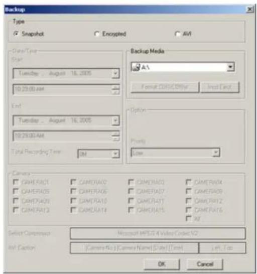
- Stop the video playback on the exact frame
- Click the desired camera to be displayed separately
- Click the Backup button on the Tools panel
-
Choose Snapshot in the Type field
-
Choose the local drive for Snapshot backup from the drop-down menu in the Backup Media field. The snapshot file will be saved to the root catalogue of the selected drive.
-
In the Watermark Checker Copy window, click Yes if this program has not been previously saved on the hard drive. Click No if it has been previously saved on the local drive.

2.2. Encrypted Backup
Encrypted backup is a unique compression method, which records all available camera inputs in a backup files can only be played with the ELMO DVR Remote Software. The K-Remote Backup during the backup process.

To perform the Encrypted Backup, do the following:
-
Click the Backup button on the Tools panel
-
Choose Encrypted in the Type field
-
Set the Start date and time from the Start menu
-
Set the End date and time from the End menu
-
Choose the local drive from Backup Media drop-down menu. The files will be saved in the LocalDrive:\KDB\backup folder
-
Set the priority of this backup process (High/Low). If set to High, this backup will have priority over other backup processes (e.g. scheduled backup).
-
Click OK
-
The current backup progress is displayed in the K-Remote Backup Server:

In the K-Remote Backup Server the user can see:
a. The IP Address of the remote Server
b. The backup title
c. The path to the backup file
d. The backup progress
e. The list of remote sites the K-Remote Backup Server has connected to and disconnected
2.3. AVI Backup
AVI backup files can only be opened with the AVI viewers (e.g. Window Media Player, Quick video recording from each camera input is saved as a separate file with an *.avi extension. MUST be running during the backup process.
![Backup Type Snapchat Encrypted AVI Date/Time Start Tuesday . August 16.2005 10:29:00 AM End Tuesday . August 16.2005 10:30:00 AM Total Recording Time 1M Backup Media Path Select Media Camera COM/CDRStar Final Text Option Priority Low Camera CAMERA01 CAMERA02 CAMERA03 CAMERA04 CAMERA05 CAMERA06 CAMERA07 CAMERA08 CAMERA09 CAMERA10 CAMERA11 CAMERA12 CAMERA13 CAMERA14 CAMERA15 CAMERA16 All Select Compressor Microsoft MPEG-4 Video Codec V2 AVI Caption : [Camera No] [Camera Name] [Date] [Time] Left Top OK Cancel](/content/2026/05/941759/images/b795446bbd5ce93e831bd478ebd4e339e070b0fb6730ce1f5ebb52104ee3e11f.jpg)
To perform the AVI Backup, do the following:
1.
Click the Backup button on the Tools panel

Note
The size of the AVI backup file will on the video recording settings. The size one-minute AVI video recording can fluctuate between 1.3MB and 2.5MB
-
Choose AVI in the Type field
-
Set the Start date and time from the Start menu
-
Set the End date and time from the End menu
-
The Total Recording Time will be displayed in the drop-down menu. When backing up lengthy video recordings, this menu will have 5, 10 and 30 minute, and 1 hour backup options that can be chosen recording time
-
Click Select Media to choose the destination for the AVI backup

a. Enter the descriptive File Name for the AVI backup file
b. Click Browse to select the local drive and folder for the AVI backup
c. Browse through the local drives and select the desired folder. If no custom folder is s will be saved to LocalDrive:\kdb\BACKUP_AVI folder.
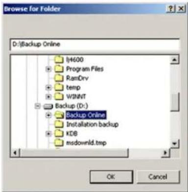
d. Click Ok
-
Set the Priority of this backup process (High/Low). If set to High, this backup process will have priority over other backup processes (e.g. scheduled backup).
-
Select all desired cameras from the Camera list. Only the video recordings from selected ca The server will create backup files with the custom file name and the camera number for Closing Time [1].avi; Closing Time [5].avi, Closing Time [9], etc. In this example, 3 AVI bac cameras 1, 5 and 9.
-
Select the video codec for the AVI backup from the Select Compressor field. Select the codec name displayed for the list of all available codecs.

Attention: It is highly advisable to leave the default codec chosen by the server - it is always the latest available codec. (In this example, Microsoft MPEG-4 Video Codec V2) The only reason to change the is to play back the AVI backup file on the older system with older codecs installed.
- Select the desired AVI Caption format for the AVI file. Select the default caption format for the list of all available caption formats. AVI Caption text will be overlaid on the AVI video recording. Select Disable for no caption text overlay.
![Disable ✓ [Camera No.] [Camera Name] [Date] [Time] [Camera No.] [Date] [Time] [Camera Name] [Date] [Time] [Camera No.] [Camera Name]](/content/2026/05/941759/images/9cc2a8c52b704b63d4a116db6438150e0535d97597392daa359fb58d4d6be105.jpg)
- Select the position for the AVI caption from the list. The caption position determines the position of the Caption text overlay on the AVI video recording. Select the default caption position (Left, Top) for the list of all available caption positions.

-
Click OK to start backup process.
-
The backup progress window and the pointing icon on the top of the screen will be dis the backup process.
-
The current backup progress is displayed in the K-Remote Backup Server:
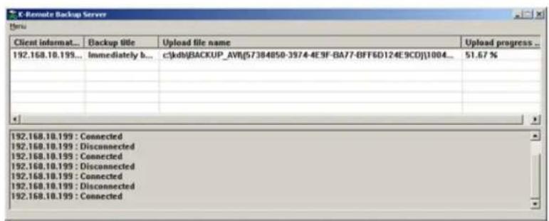
In the K-Remote Backup Server the user can see:
a. The IP Address of the remote Server
b. The backup title
c. The path to the backup file
d. The backup progress
e. The list of remote sites the K-Remote Backup Server has connected to and disconnected
PACDM ^TM Integration
1. Setting up Text Overlay
Your ELMO DVR can be configured to display and capture current PAC activity on any camera support.
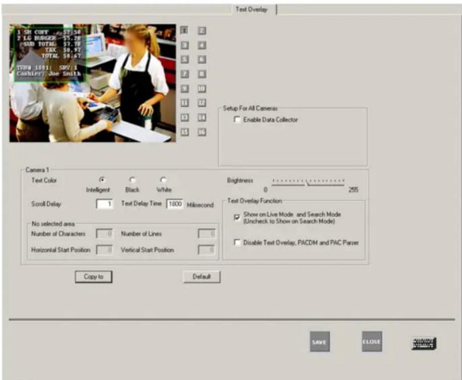
To set up PAC Text Overlay on a camera, do the following:
- Click Setup on the main screen
- Click the Text Overlay tab
- Select the camera on which you wish to see text overlay
- On the video window draw a rectangular box around the area for which you would like
- Select Black/White for the text color. Selecting Intelligent will set the text color to the opposite color of the background. Example: If the background is dark the text color would be white. If the background is bright the text color would be black.
- Adjust the Brightness according to desired background sensitivity.
- Select Show Text Overlay on Live Mode to display text inserter on live mode.
- Enter the Number of Characters per line.
- Set the Horizontal Start Position with respect to the rectangle's left edge.
-
Set the Vertical Start Position with respect to the rectangle's top edge.
-
Enter the Scroll Delay to determine the number of frames delayed when text scrolls up.
-
Enter the Number of Lines to display in the rectangle.
-
Enter the Text Delay Time. If there is no text input for a long time, the text will disappear automatically.
-
In the Setup For All Cameras menu, check off the Enable Data Collector checkbox, to start collecting data from the connected POS.
-
In the Text Overlay Function menu,
a. Check off the Show on Live Mode and Search Mode checkbox to show the Live and Search modes or leave it unchecked to show on Search mode only
b. Check off the Disable Text Overlay, PACDM and PAC Parser checkbox to overlay on ELMO DVR Server.
- ELMO DVR User Manual v5.01
- Table of Contents
- ELMO DVR Server 1
- Introduction ...... 2
- Starting ELMO DVR Server 5
- Configuring ELMO DVR Server 13
- Search on ELMO DVR Server 86
- Backup on ELMO DVR Server 101
- Introduction
- Welcome
- Important changes to ELMO DVR, v.5
- Limited Warranty
- General
- Precautions
- Unpacking
- ELMO DVR Back View
- Starting ELMO DVR Server
- Logging In/Out
- ELMO DVR Server Main Screen
- ELMO DVR Server Main Screen Features:
- About
- Help
- Location: Boston
- Server ID: 110-998
- 2006/10/31 14:09:13
- Camera panel
- Note
- Sensor and Control panel
- Screen Division
- PTZ mode
- PTZ cameras can be controlled from:
- In the PTZ window the user can:
- The PTZ window can be controlled with:
- The main areas of the PTZ mode window are:
- To configure the presets for a PTZ camera, do the following:
- Program the desired Preset with the PTZ window buttons:
- OR
- Program the desired Preset with the in-cameo PTZ function:
- Program the desired Preset with keyboard:
- Configuring ELMO DVR Server
- Hardware Setup - Camera Setup
- Overview
- Creating/Modifying Camera Settings
- To setup all connected cameras, do the following:
- Hardware Setup - Sensor Setup
- Overview
- Creating/Modifying Sensor Settings
- To configure the available sensors, do the following:
- To customize the Alarm for Sensor activation, do the following:
- Hardware Setup - Control Setup
- Overview
- Active Time
- Dwell Time
- Creating or Modifying Control Settings
- To configure the available controls, do the following:
- Hardware Setup - External Monitor Se
- Overview
- Creating or Modifying External Monitor Setting
- To set up an External Monitor do the following:
- The Preset Touring & Alarm/Preset Se 3.5.1. Overview
- Configuring Preset Touring & Alarm / Preset
- Motion Setup
- Overview
- Setup for individual camera
- To set up each individual camera, do the following:
- To draw the Motion detection zones on the selected camera, do the foll
- Individual Camera Adjustment
- Setup For All Cameras
- Setup For All Cameras - Recording/Display Op
- Recording Frame Rate per Camera
- Recording Frame Rate per Camera - Advance Setup
- In the Advanced Setup:
- Schedule Setup - Simple Mode
- Overview
- Creating a quick recording schedule
- Creating a custom holiday
- Copying a schedule to other cameras
- Schedule Setup - Advanced Mode
- Example
- Screen Division
- Communication Setup
- Overview
- Configuring Communication Setup
- Server Information
- Overview
- Configuring Server Information Setup
- Configuring Main Screen appearance
- Display Server Information:
- Display Camera Status Bar:
- Display Control Status Bar:
- Display Sensor Status Bar:
- Display Motion Detection Grid:
- Check/uncheck to save image as JPEG/BMP
- Disable Video on Main Screen:
- Display Snapshot Button
- ELMO DVR Information
- This part of the menu contains the following information about the ELMC
- Additional Configurations
- Enable Intelli Search Tooltip:
- Date Display Format:
- Sensor Type:
- Export Setting:
- Import Setting:
- Setting the System Clock
- Get Time:
- Set Time:
- Switching to the Daylight Saving Time
- Password Setup
- Overview
- Setup List
- Creating new users
- Deleting existing users
- Audio Settings
- Overview
- Configuring Audio Setup
- System Setup
- Overview
- Configure backup schedules
- Configure System Restart Time
- Synchronize System Clock with NTP Server
- Watermarking
- More about Watermarking
- Checking Authenticity of a Watermarked Ima
- Creating Scheduled Backup
- Saving to the remote drive.
- To delete a schedule, do the following
- Panic and Sensor Backup
- Network Port Setting
- Video Loss Alarm
- To configure the Video Loss Alarm menu, do the following:
- Select the Num of days to Store Data
- Video Format
- Storage Structure Setup
- Understanding ELMO DVR storage structure:
- Overview
- The Storage Structure tab displays the following:
- Formatting ELMO DVR File Structure
- E-Map Setup
- Overview
- Drawing a map
- Configuring Emap
- Control:
- To add the camera icon on the E-map, do the following:
- Sensor:
- Delete Cameras/Controls/Sensors from Emap
- Delete/Change the E-Map bitmap image, do following
- E-Map on the Main Screen
- View Log Records
- Overview
- Viewing Log Records
- Email Setup
- Overview
- Triggered Sensor(s)
- Video Loss
- Scheduled Server Status
- Configuring Email Setup
- Intelli-Guard™
- Overview
- Suggestions for using Intelli-Guard™
- General Intelli-Guard™ configurations
- Surveillance target zone (Area) configurations
- Count target zone (Gate) configurations
- Object Speed:
- Suggestions for using Object Speed
- Virtual Ruler
- Overview
- Configuring Virtual Ruler
- To draw a Virtual Ruler, do the following:
- Example,
- Intelli-Zone™
- Overview
- To set up Intelli-Zone for each camera, do the following:
- Setting up Intelli-Zone target areas
- To Set up Intelli-Zone target areas, do the following:
- To associate a target area with another camera, do the following:
- Motion Tracking
- Overview
- Define On/Off Time
- VideoLogix™ Setup
- Overview
- Configuring VideoLogix™
- To configure the camera settings, do the following:
- Configuring Object/Alarm type
- Configuring Area alarm
- Configuring CrossWire alarm
- To configure CrossWire alarm, do the following:
- Configuring Idle alarm
- To configure Idle alarm, do the following:
- Configuring Missing alarm
- Configuring Stop alarm
- To configure Stop alarm, do the following:
- Configuring Direction alarm
- To configure Direction alarm, do the following:
- Configuring Passthrough Counter alarm
- To configure Passthrough Counter alarm, do the following:
- VideoLogix on the Main Screen
- Snapshot Setup
- Overview
- Configuring Snapshot Setup
- To configure the Snapshot setup, do the following:
- c. Prefix extension:
- Search on ELMO DVR Server
- The main areas of the Search window are:
- Time Panel
- Current Date and Time
- Calendar
- Clock
- Timeline Bar
- 24-hour Timeline
- Camera Activation Buttons
- Camera Scroll Bar
- Timeline Marker
- Video Recording Bars and Types of Recording
- Playback Control Panel
- Tools Panel
- Video Recording Playback
- Snapshot Function
- To use the Snapshot function, do the following:
- Panorama Function
- To use the Panorama function, do the following:
- Image Zoom In/Zoom Out
- Using Bookmark
- To use the bookmark, do the following:
- Advanced Search Panel
- Index Search Panel
- In the example above,
- Note: the following conditions had to be met for this sensor recording to
- Example 2,
- Index Search
- Object Search
- Image Settings Panel
- Backup on ELMO DVR Server
- Quick CD Backup
- To perform a Quick Backup, do the following:
- Manual Backup
- Backup types:
- Snapshot Backup
- Browse Image
- Encrypted Backup
- AVI Backup
- Email Backup
- Emailing a Snapshot
- Emailing an AVI Video
- Multi-CD Backup
- ELMO DVR Remote
- Starting ELMO DVR Remote
- Before connecting to a remote site, please ensure the following:
- Logging In
- Creating New Remote Site Connection
- Main Screen
- The areas of the ELMO DVR Remote main screen are:
- Connecting to the Remote Site
- Main Screen
- Connections menu
- Viewing the cameras on the connecte remote site
- Using Multi-Site tool
- Disconnecting from the Remote Site
- Configuring ELMO DVR Remote
- About ELMO DVR Remote
- Configuration Setup
- To setup the Configuration Setup, do the following:
- Communication Setup
- Other Setup
- Search on ELMO DVR Remote
- Local Backup Search Categories
- Backup Data
- Removal HDD Drive Data
- Server Current Screen
- Server Search Data
- Local Search on ELMO DVR Remote
- To search video recordings stored locally, do the following:
- Search Window in the Local mode
- Time Panel
- Playback control panel.
- Camera Selection Panel.
- Searching a Connected Remote Site
- To search a remote site, do the following:
- Backup on ELMO DVR Remote
- Automatic Backup
- Automatic Backup of the video recordings viewed remotely:
- Automatic Backup of the video recordings searched remotely:
- In the K-Remote Backup Server the user can see:
- PACDM TM Integration
- Setting up Text Overlay
Brand : Elmo
Model : DVR
Category : Video recorder