
VR-X10 - Tablet Getac - Free user manual and instructions
Find the device manual for free VR-X10 Getac in PDF.


User questions about VR-X10 Getac
0 question about this device. Answer the ones you know or ask your own.
Ask a new question about this device
Download the instructions for your Tablet in PDF format for free! Find your manual VR-X10 - Getac and take your electronic device back in hand. On this page are published all the documents necessary for the use of your device. VR-X10 by Getac.
USER MANUAL VR-X10 Getac
| VR-X10 DVR System | |
| Terminal connector for DC IN | Terminal connector for GPIO x 2 |
| D-sub to BNC cable Electrical wire x 3 | |
| Fuse tap (ignition) -5A | 15A inline fuse |
| GPS antenna Wi-Fi/BT | antenna x 2 |
| Mounting kit (racket and screw x 4) | Key x 2 |
2. Identifying Components
Front Panel
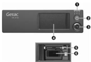
Rear Panel
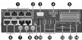
No. Descriptions
- SUPPLED
- Green light: HDD activity
Security door LED - Green light: Door locked
- Red light: Door unlocked
Recording LED - Blue light: Video recording in progress
② Power button: Press to power on VR-X10.
Power LED - Red light (for 10 seconds): DC power-in
- Green light: Software ready
Door lock: Use the key/software to unlock the door.
4 Security door: Protects the removable storage inside (if existing). The door is automatically locked when closed.
⑤ CFast connector: Allows the use of a CFast card for removable storage.
6 USB 3.0 connector: Allows the use of an USB disk for removable storage. (See "Recommended USB Disks" on the reverse side for more information.)
| No. | Descriptions Remarks | |
| 1 | 802.3af PoE ports (1 to 4): Connects up to four IP cameras. Each port has a status LED. | |
| 2 | RJ45-type audio in connectors: Connects up to two wireless microphones. | Wireless microphone model: WM-T2400M |
| 3 | Video capture connector: Provides 8-channel composite video inputs and 4-channel audio inputs. | |
| 4 | DC-in connector: Connects to vehicle ignition and battery with the 3 electrical wires provided. | See “DC-in Connector Pin Assignments” on the reverse side for wiring information. |
| 5 | GPIO ports: Provides additional control lines. There are 20 GPIO pins in two groups of 10 pins. | See “GPIO Connector Pin Assignments” on the reverse side for wiring information. |
| 6 | RJ45 connectors (LAN 1 and LAN 2): Provides 10/100/1000 base-T Ethernet connection. | LAN 2 supports PXE. |
| 7 | GPS antenna connector | |
| 8 | Wi-Fi/BT antenna connectors (Auxiliary and Main) | |
| 9 | Combo audio connector: Connects a headset microphone. | |
| 10 | USB 3.0 connector | |
| 11 | USB 2.0 connectors (1 to 3) | |
| 12 | Control unit connector: Connects to the CU-D50 control unit. | CU-D50 is an optional item. |
| 13 | Mini-HDMI connector: Connects to a monitor supporting HDMI interface. | |
| 14 | Mini DisplayPort: Connects to a monitor supporting DisplayPort interface. |

References
Pin Assignments
DC-in Connector Pin Assignments

GPIO Connector Pin Assignments

Notes on GPIO:
| Pins | Low / High Active | Input Voltage | When using a digital/O device, you must ground the device by connecting it to the metal part of the VR-X10 cabinet. This common return path is needed as the reference point for high/low voltage measurement. |
| I/O In 1, 2, 5, 6 | Low Active | 0 V | |
| I/O In 3, 4, 7, 8 | High Active | 6 V-24 V |
| Pins | Battery Mode | Output Voltage / Current |
| IO Out 1, 2, 3, 4 | Vehicle Battery Mode | Vehicle Battery Voltage / 0.75 A |
| VR-X10 Internal Battery Mode | 6.3 V~8.4 V / 0.75 A |
Recommended USB Disks
The below USB disk models have been tested
as fully compatible with VR-X10.
• SanDisk Ultra® USB 3.0 Flash Drive
• Kingston DataTraveler G4
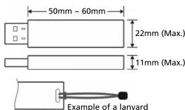
NOTE: See the figure at the right for the USB disk size supported by VR-X10. Also, you are advised to attach a lanyard to the USB disk for easy removal of the disk.
More Information
See Installation Diagram for more information.

Cautions and Notices
This equipment is designed for use and installation in a vehicle. It can be mounted in a vehicle's center console or trunk.
Safety Cautions
- This symbol (a lightning flash in a single) is intended to alert the user to the presence of uninsulated voltage within the product's enclosure that can be high enough to constitute a risk of electric shock to human bodies.
- This symbol (an exclamation mark in triangle) is intended to alert the user to the presence of important operating and maintenance information in the document(s) accompanying the product.
- To reduce the risk of electric shock, do not remove the cabinet cover. There are no user-serviceable parts inside. Contact qualified service personnel if servicing is required.
- Do not expose the equipment to rain or moisture.
- Keep the equipment away from risks of dripping or splashing liquids.
- Allow adequate ventilation around the equipment. Do not cover or block any ventilation openings.
- Use the recommended accessories only.
Battery Cautions
There is danger of explosion or fire if the battery is handled improperly.
- Replace only with the same or specified type.
- Do not disassemble or dispose of in fire.
- Do not store in temperatures above 60^ .
- Use specified charger for rechargeable batteries.
- Do not recharge the battery if it is not a rechargeable type.
- Do not leave the battery in a vehicle exposed to direct sunlight for a long period of time with doors and windows closed.
- For memory backup battery: There is danger of explosion if the battery is incorrectly replaced. Replace only with the same or equivalent type. Consult qualified service personnel when replacement is required.
FCC Regulations
This device complies with Part 15 of the FCC Rules. Operation is subject to the following two conditions: (1) This device may not cause harmful interference, and (2) this device must accept any interference received, including interference that may cause undesired operation.
To assure continued compliance, follow the attached installation instructions and do not make any unauthorized modifications.
FCC Note:
This equipment has been tested and found to comply with the limits for a class A digital device, pursuant to Part 15 of the FCC Rules. These limits are designed to provide reasonable protection against harmful interference when the equipment is operated in a commercial environment. This equipment generates, uses, and can radiate radio frequency energy, and if not installed and used in accordance with the instruction manual, may cause harmful interference to radio communications. Operation of this equipment in a residential area is likely to cause harmful interference in which case the user will be required to correct the interference at his own expense.
Warning:
To assure continued FCC emission limit compliance, the user must only use shielded interface cables when connecting to external units. Also, any unauthorized changes or modifications to this equipment could void the user's authority to operate this device.
Brand : Getac
Model : VR-X10
Category : Tablet