
55L35B5U - Video Conferencing System HISENSE - Free user manual and instructions
Find the device manual for free 55L35B5U HISENSE in PDF.


| Product Type | Video Conferencing System / LCD Display with Splicing Capability |
| Model | 55L35B5U |
| Display Size | 55 inches |
| Overall Dimensions (W x H x D) | 1213.6 × 684.3 × 94.4 mm |
| Net Weight | 28.1 kg |
| Resolution | 1920 × 1080 (Full HD) |
| Brightness | 500 nits |
| Contrast Ratio (Typical) | 1200:1 |
| Response Time | 8 ms |
| Viewing Angle | 178° (CR≥10) |
| Color Support | 16.7M (8-bit), 72% NTSC color gamut |
| Backlight Type | LED |
| Backlight Life | 30,000 hours |
| Power Supply | 100–240V AC, 50/60 Hz |
| Rated Power Consumption | 240 W |
| Operating Temperature | 0–50 °C |
| Operating Humidity | 10%–80% RH (non-condensing) |
| Input Interfaces | DVI, HDMI (MHL), HDMI 4K, DP, VGA |
| Output Interfaces | DP loop-through (supports 4K), RS232 (RJ45) |
| Control Interface | RS232 input and looping-out via RJ45 (568B standard) |
| Key Features | Ultra-narrow bezel, 4K input support, DP loop-through, 0°/90°/180°/270° image flip, automatic signal detection, multi-screen splicing (up to 2x2 or larger), matrix linkage |
| Included Accessories | Power cord, Ethernet cable, hooks (4x), remote control, RS232 connector, infrared receiver, adjusting screws (8x), hook screws (8x) |
| Surface Treatment | Haze 25%, 3H hardness (front polarizer) |
| Maintenance | Clean with soft cotton cloth; avoid hard objects, water splashes, and extreme environments |
| Safety | Grounding required; do not disassemble; avoid moisture and lightning (unplug during storms) |
Frequently Asked Questions - 55L35B5U HISENSE
User questions about 55L35B5U HISENSE
0 question about this device. Answer the ones you know or ask your own.
Ask a new question about this device
Download the instructions for your Video Conferencing System in PDF format for free! Find your manual 55L35B5U - HISENSE and take your electronic device back in hand. On this page are published all the documents necessary for the use of your device. 55L35B5U by HISENSE.
USER MANUAL 55L35B5U HISENSE
Read the manual carefully and ensure you have fully understood its contents before operating this device for the first time.
Dear user,
Hello! Thank you for purchasing the products of Hisense. We believe this new product will bring you infinite joy. Before using this product, please read the guide and keep it properly. The company shall not be liable for any accidents resulting from violation of the safety precautions and instructions in this manual.

There is high pressure in this product; the user must not open the shell without authorization. The non-maintenance personnel shall not repair or replace the parts without authorization for avoiding electric shock and fire accidents.

Please use clean and soft cotton cloth to clean and maintain the whole machine. It is prohibited to use hard objects to carve, knock, impact or rub the display with various abrasive objects. In the process of installation, placement and use, the product should avoid water drop and splash. In case of thunderstorm and other weather, the power plug and cable TV (or outdoor antenna) should be unplugged quickly so as not to cause lightning damage.
This product is a kind of equipment (I Type) with grounding .
Copyright ⒶAll rights reserved by Hisense
Any part of this manual, including text, pictures and graphics, belongs to Hisense. Without written permission, no unit or individual may extract, copy, translate or modify the whole or part of this manual in any way. Unless otherwise agreed, the company will not provide any representations or warranties to this manual through a declaration or implication.
This manual is used as a guide. The photos, pictures, charts and illustrations provided in the manual are only used for explanation. If there is any difference between the product and the specific product, please refer to the actual product. Hisense may update this manual due to product version upgradation or other requirements.
Hisense recommends that you use this manual under professional guidance.
Brand Statement
This is a registered trademark for Hisense. The other trademarks involved in this manual are owned by the specific owners.
Responsibility Statement
- Within the scope of the maximum allowed by law, the product described in this manual (including its hardware, software, firmware, etc.) is provided in a way that is "in accordance with the status quo". So there could be flaws, errors or failures, and Hisense won't provide any form of guarantee, including but not limited to such guarantee (marketability, satisfaction with the quality, suitable for a particular purpose and no infringement of third party rights, etc.). And Hisense also will not compensate for any special, incidental, accidental or consequential damages arising from the use of this manual or the use of the company's products. This damage includes, but is not limited to, loss of business profit, loss of data or loss of documentation.
- When using this product, please follow the applicable laws strictly. Hisense shall not assume any liability if the product is used for infringement of third party rights or other improper uses.
This manual is applicable to the following products:
Product Model
46L35B5U/55L35B5U

CONTENTS
Contents 3
Chapter 1 Introduction....4
Chapter 2 Product Introduction....6
2.1 Product Advantages ....6
2.2 Product Characteristics ......6
2.3 Technical Specifications ....7
2.4 System Connection Mode 8
2.5 Common Fault Handling....10
Chapter 3 Interface and Dimension....11
3.1 Interface Specification .... 11
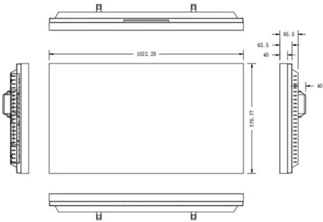
3.2 Product dimensions....11
Chapter 4 The Control Software....14
4.1 Settings of the software....15
4.2 Address settings for the splicing controller (setting ID)....15
4.3 Single machine operation....16
4.4 Splicing operation....16
4.5 Large-size screen splicing and signal source selection....17
4.6 Matrix linkage .... 17
4.7 Scene default....18
4.8 System settings....18
Chapter 5 Line Order of RJ45 Transfer Interface 26
Chapter 6 Packaging list....27
Chapter 1 Introduction
The purpose of this section is to ensure that the user is able to use the product correctly through this manual to avoid any risk or loss of property in the operation. Before using this product, please read the product manual carefully and keep it for future reference
Convention of symbols
For the symbols that appear in the document, the instructions are as follows:
| Symbols Instructions | ||
 | Instructions | This is the description text, which indicates the complement and interpretation of the text. |
 | Attention | This is the attention text, which means to remind users of important actions or to guard against potential damage and property loss. |
 | Warning | This is the attention text, which warns users against potential death or serious injury risk. |
Safety precautions

Warning
- In the process of product installation and use, all electrical requirements of the state and the use area must be strictly observed.
- To reduce the risk of fire or electric shock, the product should not be exposed to rain or moisture.
- When installing wiring in a building, it should be embedded in easy-to-use power-off equipment
- When the product is installed on the wall or ceiling, make sure the product is firmly fixed.
- If the product is not working properly, please contact the company.
- Do not disassemble or modify the product in any way. The company does not bear any responsibility for any unauthorized modification or maintenance.

Attention
- Avoid placing products in vibration or impact environments and away from electromagnetic interference. (ignoring this could damage the product)
- Do not touch the radiator parts directly, so as not to cause scalding.
- Indoor products should not be installed in the environment where water or other liquids may be sprayed.
- Do not use products in extreme heat, extreme cold, dust, corrosion or high humidity. Please refer to the product parameters table for specific temperature and humidity requirements.
- Avoid the heat accumulation, keep the surrounding ventilation smooth.
- If the product is not working properly, please contact the company.
- Please keep all the original packaging materials of the product properly so that when problems occur, you can use the packing materials to wrap the product and then return to the manufacturer for maintenance. The user shall be responsible for the accidental damage caused by the non-original packing materials.
Chapter 2 Product Introduction
2.1 Product Advantages
Ultra-narrow bezel: the ultimate splicing mode, the new experience of the huge screen viewing;
Customized stitching: easy to spell matrix control, the screen can realize free combination;
Simple split screen: automatic dislocation compensation, perfect seamless splicing;
Multiple controls: the control port is very complete and the control mode is free to choose.
Excellent control: multi-screen unified screen, enjoy the real big screen;
High resolution: fine screen resolution, screen zoom freely;
Highlight screen: highlight the screen to show the high quality view;
Ultra wide Angle: visual range up to 89°, each angle of wonderful view.
2.2 Product Characteristics
(1) the product supports 4K input, and when clicking 4 pieces of 1920 Mosaic screen (3840x2160), the point-to-point display can be realized, which means that the display screen is not compressed, and the display effect is clear and realistic.
(2) the product support DP loop - through, as long as the user input signal randomly, DP can output loop - through to the next screen DP input port, and this function can replace distributor and matrix (front signals access is 4 k, which means that it has replaced the 4 k and 4 k dispenser matrix) part of the function to use (product no longer needs to use signal distributor);
(3) the input signals support a 0-degree, 90-degree, 180-degree, 270-degree flip, and the rollover effect is excellent.
(4) support machine code (address code), and the line address is easy to recognize, because the user only needs to fill in the control software;
(5) it has the function of automatic signal detection. When the signal input is detected, it will automatically switch to the signal source.
2.3 Technical Specifications
| 46L35B5U 55L35B5U | ||
| Overall dimensions | 1022.28 × 576.77 × 95.5 mm | 1213.6 × 684.3 × 94.4 mm |
| Net weight | 20.8 KG 28.1 KG | |
| Physical joint | 3.5 | |
| Display parameters | ||
| Resolution | 1920 × 1080 | |
| Brightness 500 nits | ||
| Contrast (typical value) 1 | 200 : 1 (Typ.) | |
| Response time 8 ms | ||
| Visual angle 178° (Typ.) | (CR≥10) | |
| Color 16.7M (8bit) | ||
| Color gamut 72% NTSC | ||
| Surface Treatment Haze | 25%, 3H, (Front Polarizer) | |
| Back light source | ||
| Light source type LED | ||
| Light source life 30K hours | ||
| Power supply | ||
| Working voltage 100-240 | V 50/60 Hz | |
| Rated power 150 W 240 | W | |
| Working environment | ||
| Working temperature | 0 - 50 °C | |
| Working humidity | 10% - 80% RH (without condensation) | |
2.4 System Connection Mode

flowchart
graph TD
    A["Video Matrix"] -->|RS232| B["Computer"]
    C["RGB Matrix"] -->|RS232| B
    D["Video Signal"] -->|RS232| B
    B -->|Signal Input| E["Image of field"]
    style A fill:#f9f,stroke:#333
    style C fill:#ccf,stroke:#333
    style D fill:#cfc,stroke:#333
The structure of the system

flowchart
graph TD
    A["DID 1"] -->|RS232 OUT| B["DID 2"]
    A -->|signal input| C["DID 3"]
    B -->|RS232 IN| D["DID 4"]
    C -->|RS232| D
    E["PC"] --> C
    F["AC 100-240V"] --> A
    G["AC 100-240V"] --> B
    H["AC 100-240V"] --> C
    I["AC 100-240V"] --> D
    J["RS232"] --> C
    K["RS232"] --> B
    L["RS232"] --> C
    M["RS232"] --> D
The block diagram of the screen wall (2 by 2)
2.5 Common Fault Handling
When the fault occurs, please cut off the power supply immediately. Please do not attempt to disassemble the machine to repair by yourself, which may cause a further damage. You can follow the steps below, if you still can not solve the problem, please contact your local dealer or professional repairing personnel. The products are out of the warranty scope when users repair them by themselves.
| Phenomenon Disposal | |
| No boot (the power indicator light does not shine) | 1. Check whether the power line is damaged.2. Check whether the power supply is accessed to electricity.3. Verify that the power supply has been opened.4. Check whether the power switch is damaged.5. Check whether the insurance is fused. |
| All the splicing units are out of control | 1. Check whether the port settings of the splicing software are correct.2. Check whether there is a damage in the serial line, and whether it is a good connection between the product and the PC interface.3. Check whether there is a problem with the PC serial port, you can change another PC for testing.4. Check whether the address of the splicing unit is correctly set according to the address setting instructions. |
| Some individual splicing units are out of control | 1. Check whether the address of the device are correctly set.2. Check whether can control a single unit separately. |
| No VGA/DVI input of single or multiple devices | 1. Check whether the interface between the unit board and the signal source is well connected.2. Change another VGA/DVI line to test.3. Check whether the device is arranged in the corresponding input state.4. Check whether the input signal is beyond the scope of this product input.5. For DVI input, confirm the DDC capture and the output. |
Chapter 3 Interface and Dimension
3.1 Interface Specification

| NO | Definition Notes | |
| A | DVI input DVI interface input, support 1920 x 1080 60Hz | |
| B | HDMI MHLinput HDMI digital signal input, support 1920 x 1080 60Hz | |
| C | HDMI 4Kinput HDMI digital signal input, support 3840 x 2160 60Hz | |
| D | DPinput DP digital signal input, support 3840 x 2160 60Hz | |
| E | VGA input VGA analog signal input, support 1920 x 1080 60Hz | |
| F | DP output DP digital signal output,support 3840 x 2160 60Hz | |
| G | RS-232input (RJ45interface) | serial port input connects the control computer, which adopts the standard of 568B |
| H | RS-232looping-out (RJ45interface) | serial port looping-out controls B, which adopts the standard of 568B |
| I | Power supply interface 100-240V 50/60Hz AC input | |
3.2 Product dimensions
46L35B5U
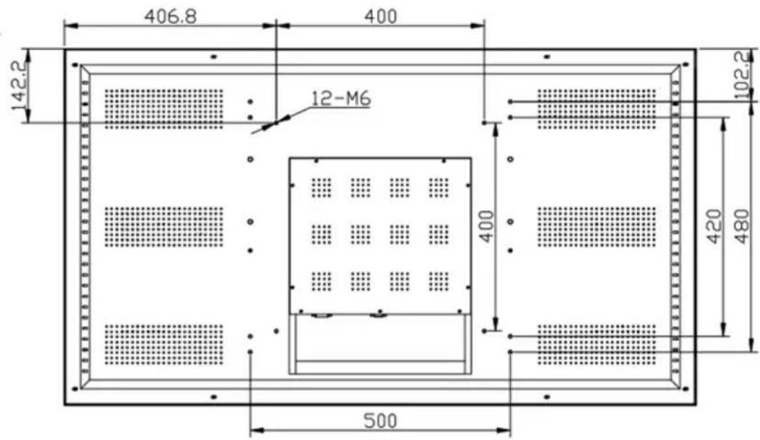
55L35B5U


Chapter 4 The Control Software
PC control software installation and Application
The system running environment: English or Chinese operating system of Windows98/2000/NT/XP/WIN7/WIN10
The minimum configuration of CPU: Dual core 2.0GHz and above
Memory: 1GB
Display card: Standard VGA, 256 color display mode and above
Hard disk: A typical installation 10M
The serial communication interface: Standard RS232 communication interface or its compatible model
Other equipment: mouse
Starting the system
Before running the system, ensure the following normal connection:
- The RS232 line of the computer for the software is properly connected to the controller.
- Both the relevant signal lines of the controller and power line are connected correctly.
System operation procedure:
1) open the power supply of the controller, the indicator light will light up.
Green stands for a startup state; orange stands for a standby state.
2) operate of the software
Extract the splicing control software.RAR, you can get the following files: user logo, automatically adjust the picture VGA, serial debugging, LCDWall.exe, LcdWall.exe.manifest, MWS_Cfg.ini. The control software is a green version, no need to be installed. Run the Lcdwall.Exe, and then it appears as shown in Fig.1.
(Note: all the operations must be open in the serial port)
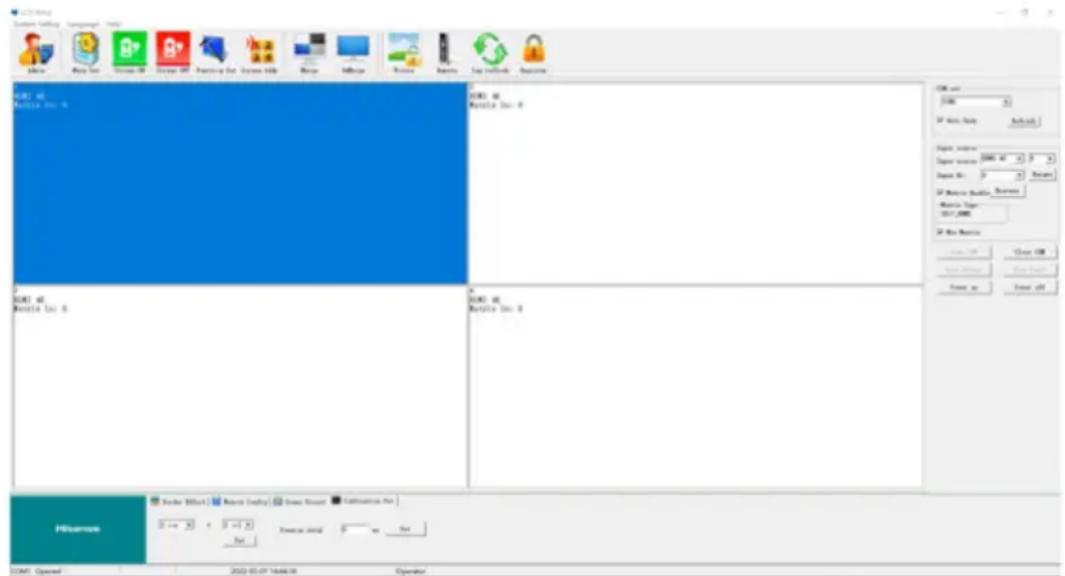
Fig.1
Note: The contents of interface may differ from the example shown above with the different version of the software; you may consult our relevant customer service staff. The function description of the operation interface is shown in Fig.1:
| Operation zone | each grid element represents the corresponding controlled screen, you can select the corresponding controlled unit through the keyboard or the mouse clicking or dragging. |
| Function zone | contains commonly used function buttons. |
| User's title zone | the users can change the displays of the title according to their own requirements. |
| Status zone | displays the port state and the operation authority state, and the current local time, date, etc. |
4.1 Settings of the software
Click the function diagram of "serial port settings", the interface is shown as in Fig.2.
Note: Click "refresh" button to mate COM automatically, and then click "open" to achieve connection.
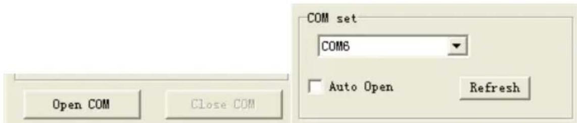
Fig.2
The ranks in the "curtain wall settings" can be set according to the actual needs. The following is an example of 2 by 2 in the WinXP
(Note: if the wall is 2 by 2, then the splicing array must be set to 2 by 2, otherwise it will fail to splice)
4.2 Address settings for the splicing controller (setting ID)
System settings ---- sequence number (setting ID) changes:
each equipment's original serial number is "1", the users can set the screen sequences according to their own needs. Administrator users can go into the "curtain wall settings" to fill in the corresponding target sequence numbers according to each screen machine's code, then click "modify" to complete modification of the serial number of the screens (Note: this function will read the screen machine's code and modify the corresponding serial number of the screens when modification).
(Note: the "system settings" button can only be operated when inputting the administrator password. The remote controller can only be used in the multimedia channel. The default administrator password is 111111, which can be modified. Please keep the new password in mind when modified)

Fig.3
4.3 Single machine operation
Fig.4 is showing the relative options.
You can choose a single or multiple splicing units to set on/off of the unit(s), and you can also right click the mouse to set the input signal, or click on the "image freezing" to freeze the current image, and click again to cancel the freezing.

Fig. 4
4.4 Splicing operation
Splicing operation is as shown in Fig.5. For multiple splicing units, 2 by 2 for example, after selecting the 4 screen, select the signal source in the signal sources, click the "execute" button to complete the splicing. You also can click on the "image freezing" to freeze the current image, and click again to cancel the freezing.
After splicing, there will be physical seams between the units, you can select the "eliminate the border" and set up corresponding values to realize the image coherence (Note: the frame value is set according to the physical frame of the screen. For example: the length of the LTI460HA03 frame is 10mm, and the value should be set to 10).
Fig.5 shows the effect of removing frames.
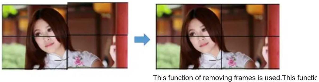
Fig.5
4.5 Large-size screen splicing and signal source selection

4.6 Matrix linkage
1) Select: Matrix linkage, and select the matrix input channel. The interface is shown as in Fig.6

Fig.6
2) Select the matrix type and configure the matrix ID. The interface is shown as in Fig.7.
(Note: different matrix selection has the different time delay)

Fig.7
4.7 Scene default
The scene default is shown in Fig.8.
It supports to save 16 kinds of scene modes, whose names can be modified. Select the mode to be saved, then click "save mode", and the model is saved. The "call mode" can call the users saved mode. The polling mode of the scenes can be started according to users needs.
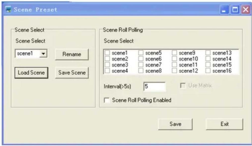
Fig.8
4.8 System settings
Click system settings, see Fig.9.
(Note: only the administrator can access the settings, password: 111111)
In this menu, the two options of Video and VGA are set by different signal sources; and each of the settings in the splicing unit will display correspondingly.
1) Color adjustment
The buttons of "brightness", "contrast", "chrominance", "could", "tone", "one key color correction" can be adjusted when selecting Video.
When choose VGA, you can only adjust the "brightness", "contrast", and "one key color correction" buttons. See Fig.9.
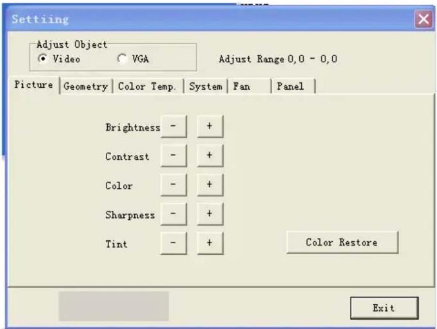
Fig.9
2) Geometry adjustment
When choose the Video, you can adjust the "horizontal position/size" and "vertical position/size". When choose VGA, the "clock", "phase", "horizontal position" and "vertical position" can be adjusted. See Fig.10.

Fig.10
3) Color temperature adjustment
When choose Video/VGA, you can adjust the colors of red, green and blue. See Fig.11.

Fig.11
4). System adjustment
In this menu, you can adjust solidified software on the machine, including the backlight brightness adjustment, the no-signal blue/black mode, the software upgrade, and the automatic adjustment function the VGA location/color. See Fig.12.

Fig.12
Terms interpretation:
| Backlight brightness | it is used to adjust the brightness of LCD lamp, and has nothing to do with signals. |
| Automatic adjustment of the VAG color | if the value is caught incorrectly in the VGA state, the display color is not normal. Now you can click this button to catch it again, it can be repeatedly clicked (Note: it is used when single screen display of the splicing unit). |
| No-signal blue screen | when you click on this button, the no-signal blue mode is on. If there is no signal, the screen displays blue. When signal is connected, it will display normally. |
| No-signal black screen | when you click on this button, the no-signal black mode is on. If there is no signal, the screen displays black. When signal is connected, it will display normally (Note: this function is practical in some special occasions such as at night time). |
| Reset | you can click this button to restore the machine to original state when your settings are in chaos (Note: do not reset unless you get the permission from the manufacturer) |
| Change of the curtain address (i.e. splicing control box address) | all the splicing control boxes addresses are originally set to “1”, the users can set the addresses according to their own needs. Firstly to display the screen machine codes, as shown in the bottom of the screen (see Fig.13 and Fig.14), then set the corresponding addresses, click “modify” to complete the changes. |
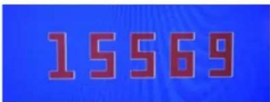
Fig.13 Machine code

Fig.14 Machine code and screen address
6) Fill the machine code and the screen address displayed in the control software into the corresponding boxes and then click "modify" to finish it. All the default addresses of the display screen are "001".
For example, in the 2 by 2 splicing screen, the machine code 15569 is showing for the fourth screen counted from left to right by column, as shown in Figure 11. When you put the 15569 into the frame, the address box of the curtain wall has been changed into 4, click “modify” to finish it, and then close it to go on for the next one.
Software upgrade: copy the software MERGE.bin from the relevant personnel of our company to the root directory of a USB drive, do not change the file's name, then insert the USB drive into the USB interface, click "software upgrade", the screen will turn into blue, and you can see the update progress of the software in the upper right corner. At the same time, the power indicator light will flash green/orange alternately. It will automatically reboot after the upgrade is completed
(Note: during the upgrade process, do not power off or pull out the USB drive, otherwise it will damage the machine).
7) Screen parameter settings

Fig.15 Screen parameter settings
8) System
(1) Click administrator
This operation software needs administrator's privilege in many places, as is shown in Fig.16 and Fig.17.
The administrator password: 111111
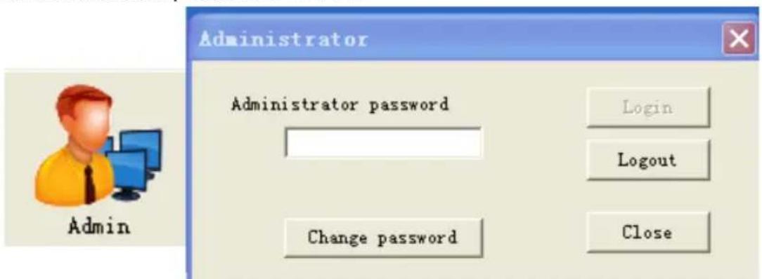
Fig.16
Fig.17
(2) Software settings
click software settings, as shown in Fig.18.

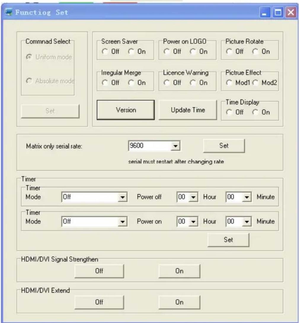
Fig.18
(3) Title settings
click "system" to open the "title settings" as shown in Fig.19.
• Title: the users can modify it according to their own needs.
- User's name: users can modify it according to their own needs.
- Company website: users can modify it according to their own needs, which can be changed into any desired one.
- User LOGO: users can modify any company LOGO, and then determine it.

Fig.19
- Open the control software, click the LOGO picture zone at the lower left corner, it can link to the website as the user designated. See Fig.20.
(Note: the computer has shown normal connection of the network)
natural_image
Abstract blue fractal pattern with glowing edges against a dark background (no text or symbols)Fig.20
• Language: users can choose Chinese and English according to their own needs.

- Registration: click "registration", see Fig.21.
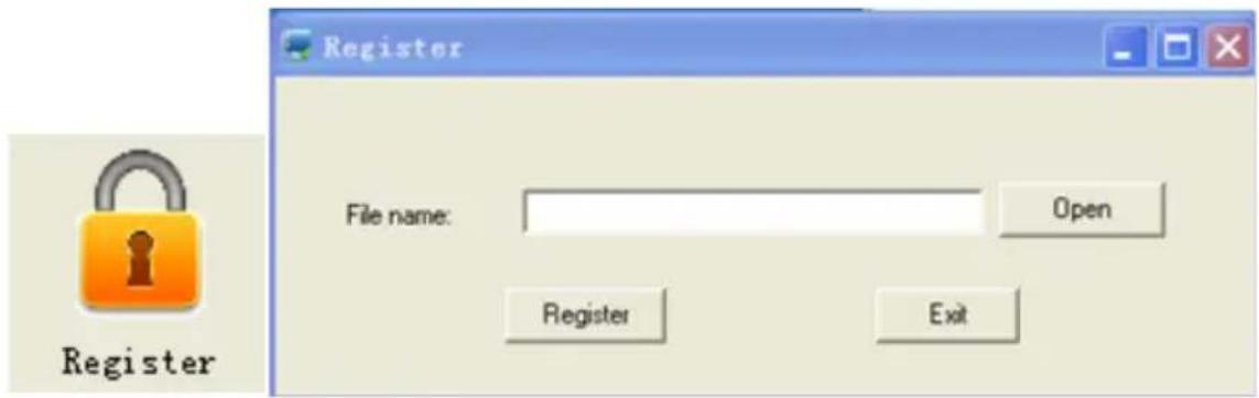
Fig.21
Chapter 5 Line Order of RJ45 Transfer Interface
RJ45 RS-232

| RJ45 DB9 | |||
| Function Pin | Colour Pin | ||
| TXD 1 Blue 3 | |||
| //// | |||
| //// | |||
| //// | |||
| GND 5 Black 5 | |||
| //// | |||
| //// | |||
| RXD 8 White 2 | |||
Chapter 6 Packaging list
| No. | Product name Unit Quantity | ||
| 1 | Whole machine / 1 | ||
| 2 | Power cord / 1 | ||
| 3 | Ethernet cable / 1 | ||
| 4 | Hook / 4 | ||
| 5 | Remote control / 1 | ||
| 6 | RS232 connector / 1 | ||
| 7 | Infrared reception | / | 1 |
| 8 | Adjusting screw | / | 8 |
| 9 | Hook screw | / 8 |
Restricted substances or element identification tables
A restricted substance or element identification form specified in the “administrative
measures for controlling the pollution of electronic information products"

| Part names | Restricted substances or elements | |||||
| Lead (Pb) | Mercury (Hg) | Cadmium (Cd) | Hexavalent chromium(CrVI) | Polybrominated biphenyls(PBB) | Polybromo-diphenyl ether(PBDE) | |
| Metal parts × | ○○○ | ○○ | ||||
| Plastic parts | ○○○ | ○○○ | ||||
| Circuit board | ×○○ | ○○○ | ||||
| Glass (if any) | ○○○ | ○○ | ||||
| Power supply (if any) × | ○○○ | ○ | ||||
| Attachment (if any) | ×○ | ○○○○ | ||||
| Instructions:1. This form is compiled according to SJ/T 11364.2. O indicates that the content of the restricted substances in all homogeneous materials in the component is below the limit specified in GB/T 26572;3. × indicates that the content of the limiting substance exceeds the limited requirements specified in GB/T 26572 for at least one homogeneous material of the component; | ||||||
- Copyright ⒶAll rights reserved by Hisense
- Brand Statement
- Responsibility Statement
- Product Model
- CONTENTS
- Chapter 1 Introduction
- Convention of symbols
- Safety precautions
- Warning
- Attention
- Chapter 2 Product Introduction
- Product Advantages
- Product Characteristics
- Technical Specifications
- System Connection Mode
- Common Fault Handling
- Chapter 3 Interface and Dimension
- Interface Specification
- Product dimensions
- Chapter 4 The Control Software
- PC control software installation and Application
- Starting the system
- System operation procedure:
- Settings of the software
- Address settings for the splicing controller (setting ID)
- Single machine operation
- Fig.4 is showing the relative options.
- Splicing operation
- Large-size screen splicing and signal source selection
- Matrix linkage
- Scene default
- System settings
- 1) Color adjustment
- 2) Geometry adjustment
- 3) Color temperature adjustment
- 4). System adjustment
- 7) Screen parameter settings
- 8) System
- Click administrator
- Software settings
- Title settings
- Chapter 5 Line Order of RJ45 Transfer Interface
- Chapter 6 Packaging list
- Restricted substances or element identification tables
Brand : HISENSE
Model : 55L35B5U
Category : Video Conferencing System