Jupiter Kore - Server OWC - Free user manual and instructions
Find the device manual for free Jupiter Kore OWC in PDF.


| Product Type | Server / Storage Expansion |
| Model | OWC Jupiter Kore |
| Form Factor | 8-bay (2U) or 16-bay (3U) |
| Drive Bays | 8 or 16 (hot-swappable) |
| Supported Drive Types | 3.5-inch SATA/SAS HDD, 2.5-inch SATA/SAS SSD (requires adapter) |
| Drives Included | Yes, pre-installed |
| Connectivity | 2 x Mini SAS HD SFF 8644 ports |
| Power Supply (8-bay) | 650W high-efficiency 1+1 redundant hot-swappable |
| Power Supply (16-bay) | 875W 1+1 redundant hot-swappable with active PFC |
| Power Supply Features | Auto-switching, load-balancing |
| Operating Temperature | 41°F to 95°F (5°C to 35°C) |
| Non-Operating Temperature | -4°F to 140°F (-20°C to 60°C) |
| Compatibility | macOS 10.15+, Windows 10+, Linux |
| Management Interface | TrueNAS SCALE Web UI (default credentials: admin / jupiter) |
| Rack Mount | Included slide rails, 4-post square-hole compatible |
| Package Contents (16-bay) | Unit, 16 drives, 2 power cables, slide rails, rail extensions, mounting hardware |
| Package Contents (8-bay) | Unit, 16 drives (note: likely copy error, actual drives match bay count), 2 power cables, slide rails, rail extensions, mounting hardware |
| Weight (8-bay) | Approximately 15 kg (33 lbs) without drives |
| Weight (16-bay) | Approximately 22 kg (48 lbs) without drives |
| Certifications | FCC Class B, CE |
| Warranty | 3-Year Limited Warranty |
Frequently Asked Questions - Jupiter Kore OWC
User questions about Jupiter Kore OWC
0 question about this device. Answer the ones you know or ask your own.
Ask a new question about this device
Download the instructions for your Server in PDF format for free! Find your manual Jupiter Kore - OWC and take your electronic device back in hand. On this page are published all the documents necessary for the use of your device. Jupiter Kore by OWC.
USER MANUAL Jupiter Kore OWC
natural_image
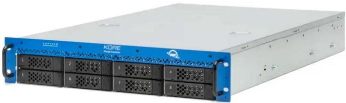
Front view of a KORE network equipment chassis with 14 drive units (no visible text or labels beyond branding)OWC Jupiter Kore 8-Bay (2U)
natural_image
Front view of a KORE server rack with multiple drive bays and blue back panels (no visible text or labels)Introduction
1.1 System Requirements
Operating System
• Mac : macOS 10.15 or later
• PC : Windows 10 or later
- Other : Linux
Hardware
- Works with any Mac or PC's RJ-45 port or through a network adapter
Supported Drives
• 3.5-inch SATA or SAS HDDs
• 2.5-inch SATA or SAS SSDs (requires an adaptersold separately)
1.2 Package Contents
OWC Jupiter Kore 16-Bay (3U)
• (1) OWC Jupiter Kore 16-bay (3U)
• (16) 3.5-inch/2.5-inch SATA HDDs/SSD
• (2) Power cable
• (2) Slide rails
• (2) Rail extensions
• (8) M5 pan head screws
• (12) M5 cage nuts
• (4) M5 enclosure securing screws
OWC Jupiter Kore 8-Bay (2U)
• (1) OWC Jupiter Kore 8-bay (2U)
• (16) 3.5-inch/2.5-inch SATA HDDs/SSD
• (2) Power cable
• (2) Slide rails
• (2) Rail extensions
• (8) M5 pan head screws
• (12) M5 cage nuts
• (4) M5 enclosure securing screws
1.3 About This Manual
The images and descriptions may vary slightly between this manual and the unit shipped. Functions and features may change depending on the firmware version or driver version, if applicable. Please visit the product web page for the most recent product requirements, specifications, and warranty information.
General Use Precautions
- Read this user guide carefully and follow all recommended usage steps and precautions.
- To avoid damage, do not expose the device to temperatures outside the following ranges:
• Environmental (Operating)
• Temperature (°F): 41° — 95°
• Temperature (°C): 5° — 35°
• Environmental (Non-Operating)
• Temperature (°F): -4° — 140°
• Temperature (°C): -20° — 60°
- Always unplug the device from the electrical outlet if there is a risk of lightning or if it will be unused for an extended period of time. Otherwise, there is an increased risk of electrical shock, short-circuiting or fire.
- Do not use the device near other electrical appliances such as televisions, radios or speakers. Doing so may cause interference which will adversely affect the operation of the other products.
- Protect your device from excessive exposure to dust during use or storage. Dust can build up inside the device, increasing the risk of damage or malfunction.
- Do not block any ventilation openings on the device. These help to keep the device cool during operation. Blocking the ventilation openings may cause damage to the device and cause an increased risk of short circuiting or fire.
Safety Precautions
- Read this user guide carefully and follow the recommended steps for assembly.
- Use proper anti-static precautions while installing drives into this enclosure. Failure to do so can cause damage to your drive mechanisms and/or the enclosure.
- Do not attempt to disassemble or modify the device. To avoid any risk of electrical shock, fire, short-circuiting or dangerous emissions, never insert any metallic object into the device. If it appears to be malfunctioning, please contact technical support.
- Never expose your device to rain, or use it near water or in damp or wet conditions. Never place objects containing liquids on the drive, as they may spill into its openings. Doing so increases the risk of electrical shock, short-circuiting, fire or personal injury.
1.4 Front View
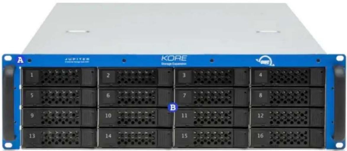
OWC Jupiter Kore 16-Bay (3U)
A (2) Rack Handles - Use to pull and remove the Callisto from a rack server cabinet.
natural_image
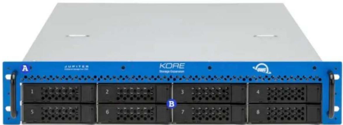
Front view of a server rack unit labeled A and B, showing 13 black rack units with ventilation grilles and a 'KORE Storage Explosion' logo (no readable text beyond labels)OWC Jupiter Kore 8-Bay (2U)
A (2) Rack Handles - Use to pull and remove the Callisto from a rack server cabinet.
(8) Drive
natural_image
Front view of a blue Jupiter storage expansion rack with black drive bays and labeled ports (no readable text beyond labels)1.5 Rear View
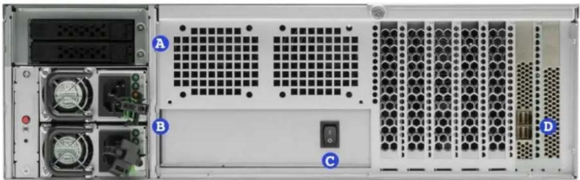
OWC Jupiter Kore 16-Bay (3U)
A. (2) Boot Drive bays – Unused with the OWC Jupiter Kore.
B. (2) Power Supply ports – Connect the power cables to power the device. Status LED Functions?
C. (1) Power Switch
D. (2) Mini SAS HD SFF 8644 ports - Connect storage expansion with an OWC Jupiter Callisto system
natural_image
Front view of a server rack unit with labeled ports (A, B, C, D) and external hardware components (no readable text or symbols beyond labels)OWC Jupiter Kore 8-Bay (2U)
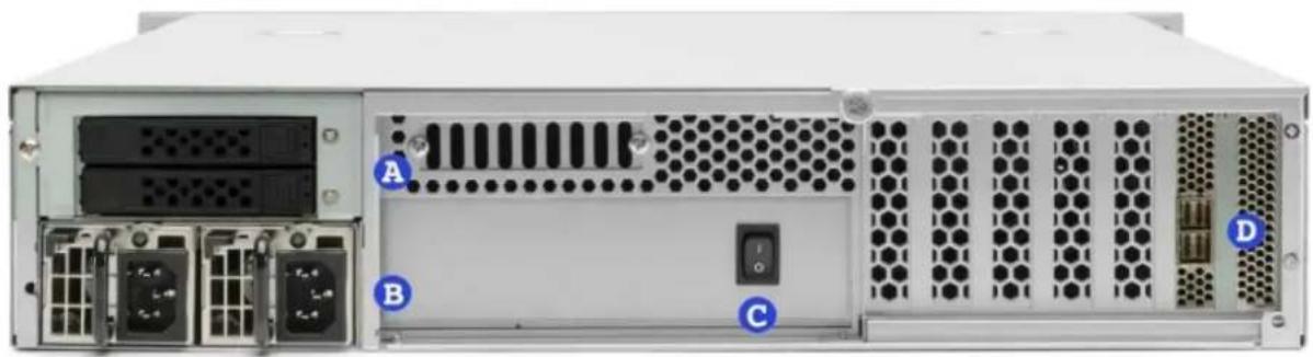
A. (2) Boot Drive bays – Unused with the OWC Jupiter Kore.
B. (2) Power Supply ports – Connect the power cables to power the device. Status LED Functions?
C. (1) Power Switch
D. (2) Mini SAS HD SFF 8644 ports - Connect storage expansion with an OWC Jupiter Callisto system
natural_image
Front view of a server rack unit with labeled ports (A, B, C, D) and internal components including drive bays and heat sinks (no text or symbols beyond labels)1.6 Side View
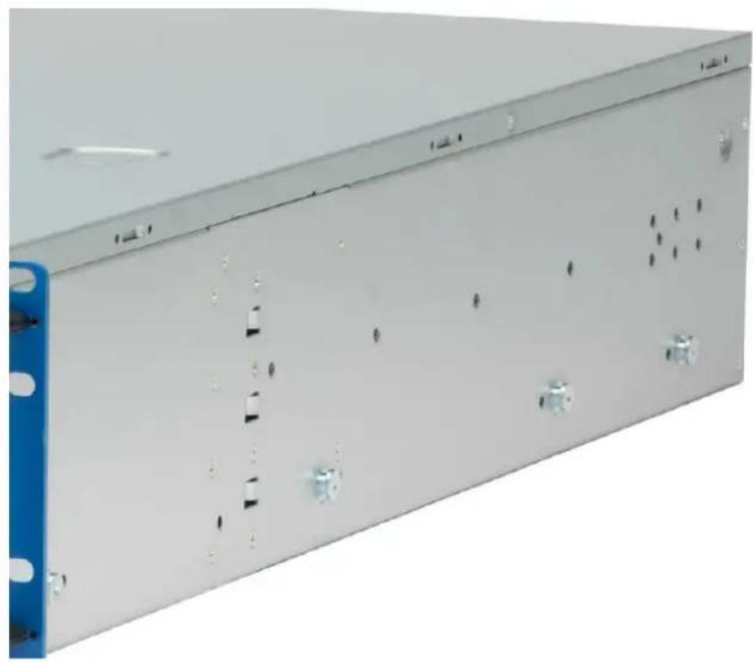
OWC Jupiter Kore 16-Bay (3U)
natural_image
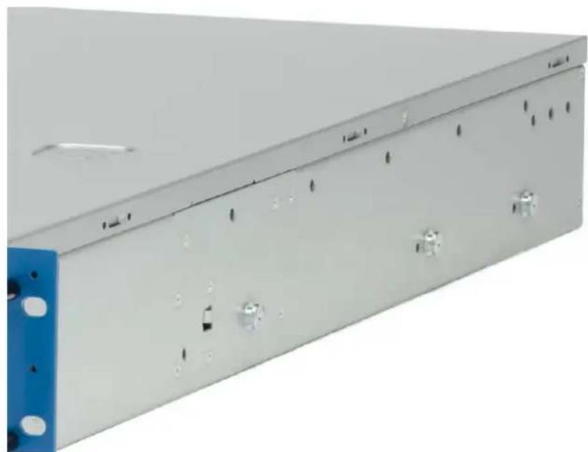
Exterior view of a server rack unit with blue connectors and ventilation slots (no visible text or labels)OWC Jupiter Kore 8-Bay (2U)
natural_image
Exterior view of a server rack unit with blue connectors and metallic casing (no visible text or symbols)Installation & Replacement
2.1 Rail Installation
The OWC Jupiter Kore comes with rack mount slide rails attached to the sides of the unit and the necessary screws and cage nuts for installing into 4-post square-hole rack systems. To install the slide rail brackets into your rack, do the following:
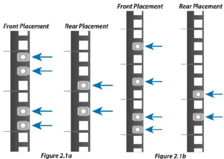
- The Jupiter Kore requires two (8-bay) or three (16-bay) rack units of space. Take note of which units in your rack that you will install your Jupiter Callisto into.
- Install the included cage nuts into your rack. Use as a guide for cage nut placement for an 8-bay Jupiter Kore; use for a 16-bay Kore.
-
On the OWC Jupiter Kore, remove the securing screw from the rail on the left and right sides as seen in Figure 2.1c.
-
Once the securing screws have been removed, remove the rail arm by sliding it toward the rear of the unit as seen in When the rail arm stops, push the release tab while continuing to slide the rail arm off. After removing the rails, set them aside taking note of the side from which they were removed.
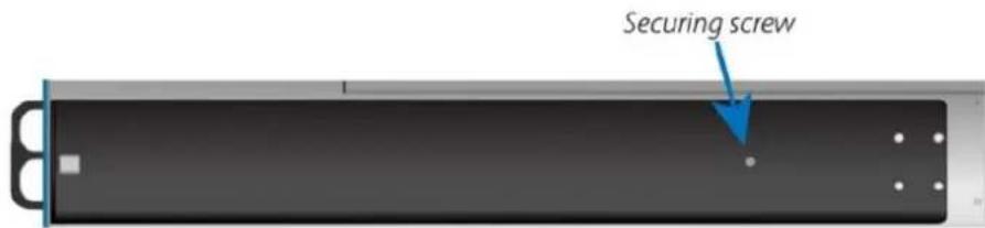
Figure 2.1c
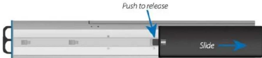
Figure 2.1d
- Remove the rail arm extensions from the accessories box and match them to the rails. Use as a guide for proper matching of rails and the extension pieces.
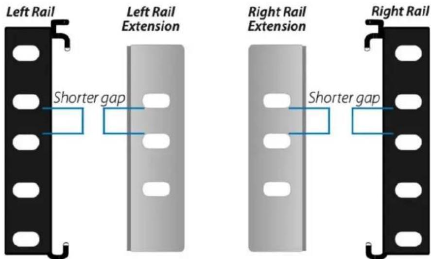
Figure 2.1e
- Install the front rails, first making sure the bottom of the rail lines up with the bottom of the designated rack units. Using Figure 2.1f as a guide for an 8-bay and for a 16-bay unit, secure the rail using two of the included M5 pan head screws.
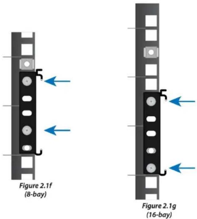
- Before securing the rear rail extension to the back of your rack, make sure to slide the extension into the rail as seen in Figure 2.1h.
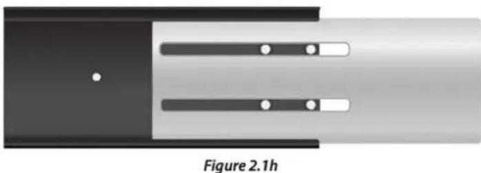
natural_image
Diagram of a mechanical component with two parallel slots and a central dot, labeled 'Figure 2.1h' (no text or symbols on the diagram itself)- Secure the rear rail extension to your rack use two of the included M5 pan head screws as seen in
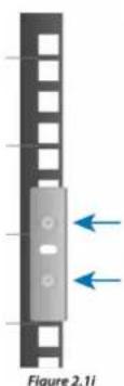
natural_image
Diagram of a mechanical component with two blue arrows indicating direction, labeled as Figure 2.1i (no text or symbols on the diagram itself)- After securing the rear rail extension to your rack, secure the rail extension to the rail using two of the included M5 pan head screws as shown in Figure 2.1j.
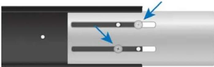
natural_image
Diagram showing two parallel sliders with blue arrows pointing to each, no text or symbols presentFigure 2.1j
- After repeating the steps for the other side, you can now move on to installing the Jupiter storage system into the rack as found in Section 2.2, Unit Rack Installation and Removal below.
2.2 Rack Installation & Removal
After installing the rails, the Jupiter Kore can be installed into the rack. The Jupiter Kore is heavy even when no drives are installed. Never lift heavy equipment by yourself and always use proper lifting techniques. It is recommended that you remove all drives from the Jupiter Kore before installing into or removing from a rack in order to avoid personal injury or damage to equipment.
Rack Installation
-
Before lifting and installing the Jupiter Kore into the rack, make sure all people involved in lifting know where the unit rails are attached to the Jupiter Callisto and how they will slide into the rack rails.
-
Using proper lifting techniques and keeping the Jupiter Kore level, lift up to the rack rails where the unit will be installed into.
-
Visually align the unit rails with the rack rails.
-
Once aligned, evenly slide the unit rails into the rack rails. Do not release the unit until it has been inserted all the way or until an audible click is heard. The click indicates that the Jupiter Kore has been inserted past the security latches as illustrated in
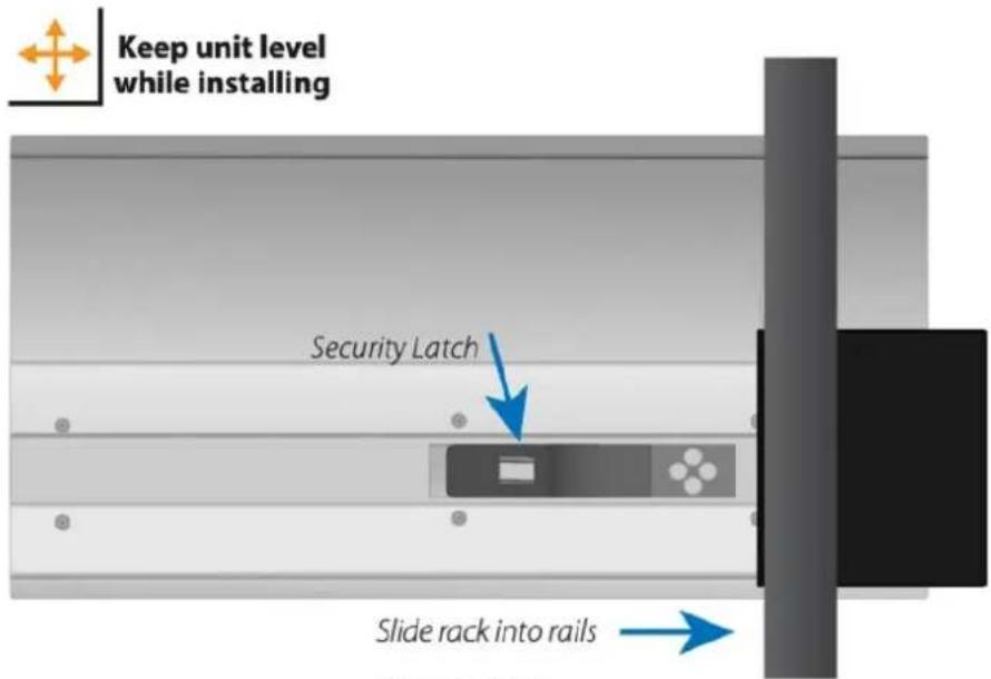
Figure 2.2.1a
- If not already done, insert the Jupiter Kore all the way into the rack until the rack ears touch the rack posts.
- Install the four included rack securing screws to finish the unit installation into the rack as seen in The 16-bay version is shown, but the screw placement is similar on the 8-bay version.
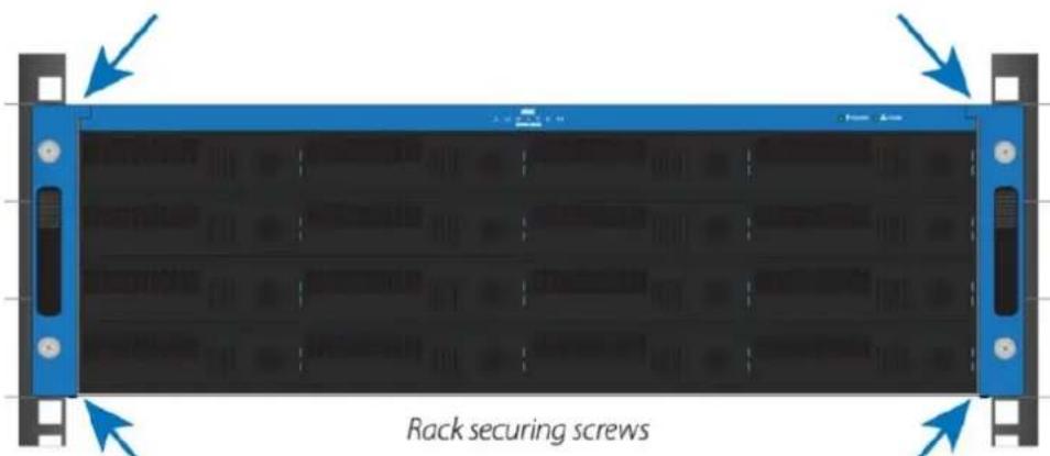
Figure 2.2.1b
Rack Removal
-
Before removing the Jupiter Kore from your rack, it is recommended that you remove all drives to make it easier to remove the Jupiter Kore from the rack and to reduce the risk of personal injury and/or equipment damage.
-
Make sure all cables including data and power are disconnected from the Jupiter Kore.
- Remove the four rack securing screws from the front of the Jupiter Kore as shown in
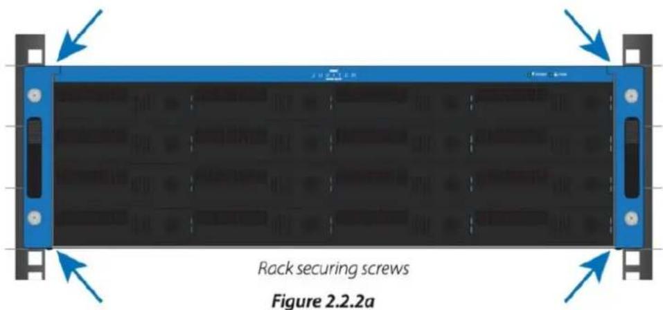
-
Using the handles, pull the rack toward you until it is stopped by the security latches.
-
It is recommended to have a second person assist the removal at this point. Press the security latches while simultaneously sliding the unit out just past the security latch as illustrated in
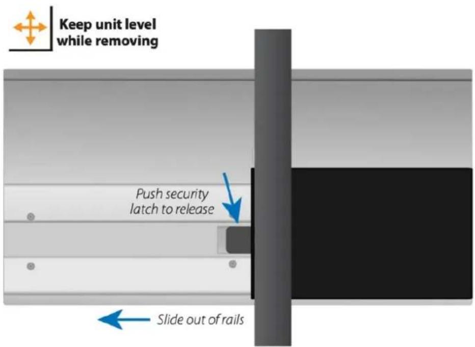
Figure 2.2.2b
- Make sure both people removing the unit have a firm grip on the rack front and base and are prepared to support the full width of the unit. Continue slowly pulling the rack out until it is free from the rails.
2.3 Drive Installation & Removal
The OWC Jupiter Kore comes with drives already installed into the individual trays to provide quicker setup time. Use the following instructions to install and remove drives from the drive bays.
Drive Installation
- Begin by placing the OWC Jupiter Kore on a static free work surface. Careful remove the drive trays from the packaging.
- Each drive tray is labeled with a number. Additionally the drive trays have locking mechanisms. Press down on the locking mechanism to lock the drive tray. A small amount of red will show indicating the drive tray is locked. Press up to unlock the drive tray. The small amount of red will no longer appear indicating the drive tray is unlocked.
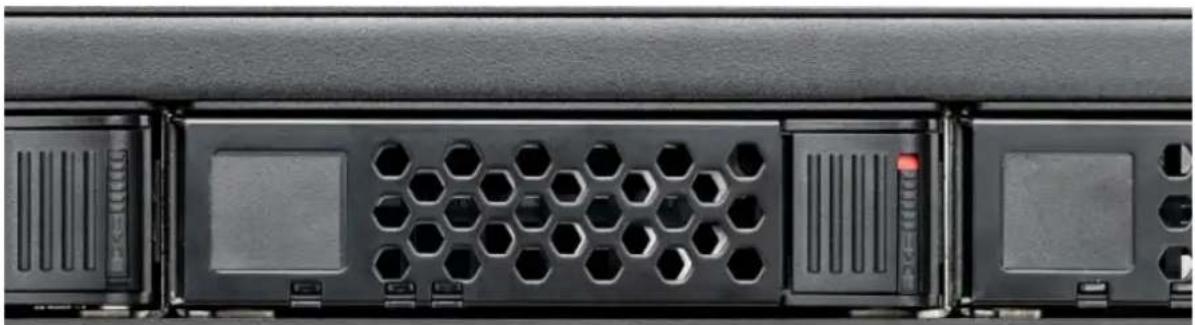
natural_image
Close-up of a black server rack with hexagonal ventilation slots and ports (no visible text or symbols)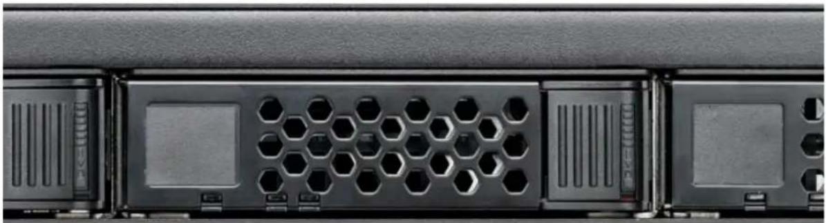
natural_image
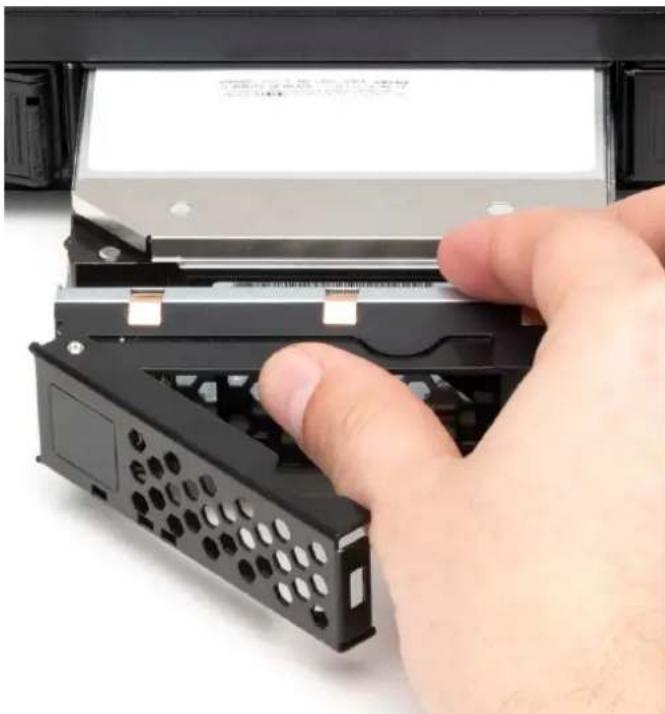
Close-up of a black server rack with hexagonal ventilation slots and ventilation grilles (no text or symbols visible)- Insert the drives, with the drive label facing upwards, in sequential order beginning from the top-left corner. Carefully push the drive tray forward into the drive bay. Do not force the drive as a minimal amount is needed. The drive will rest slightly protruded outside the drive bay.
NOTE : The drive trays have locking mechanisms. Ensure the locks are not engaged before installing the drive trays. The lock is disengaged when the locking mechanism is in the up position.
natural_image
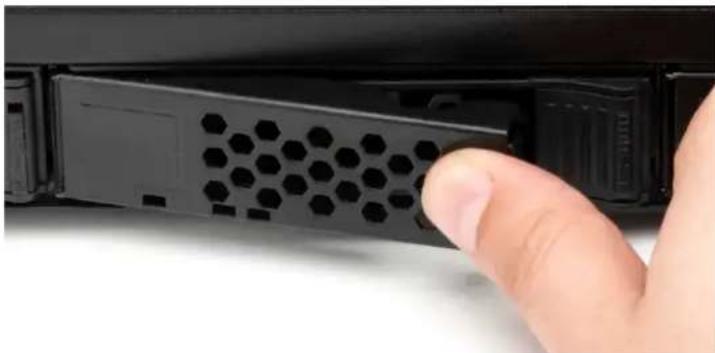
Hand inserting a black remote control into a device casing (no visible text or symbols)- Press the drive tray door to finish pushing the drive into the drive bay and completing the connection.
natural_image
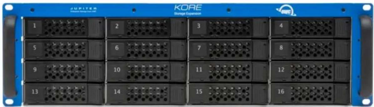
Close-up of a hand inserting a hexagonal plastic component into a black electronic device (no text or symbols visible)- Move right within the same row until full. Move onto the next row beginning from the left and moving right. Repeat this process until all the drive trays are installed into the OWC Jupiter Callisto. Lock the drive trays if desired.
OWC Jupiter Kore 16-Bay (3U)
natural_image
Front panel of a JUPITER storage expansion module showing 13 numbered rack-mounted modules (no text or symbols on panels)OWC Jupiter Kore 8-Bay (2U)

Drive Removal & Replacement
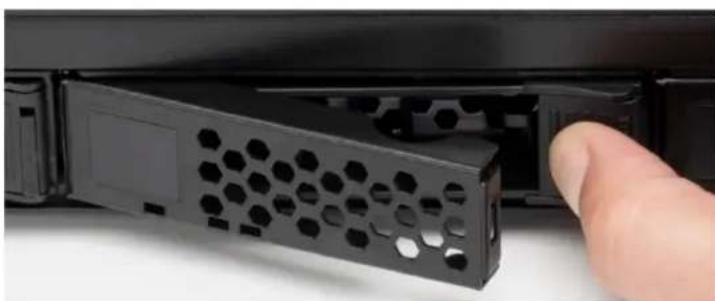
- Disengage the drive tray by pushing the tray tab to the right. The drive tray will protrude slightly from the chassis. Carefully remove the drive tray and place on a flat surface.
NOTE : The drive trays have locking mechanisms. Ensure the locks are not engaged before pushing the tray tabs to the right. The lock is disengaged when the tab is in the up position.
natural_image
Close-up of a black hexagonal device with a finger pointing to its side panel (no text or symbols visible)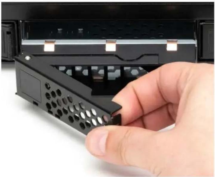
natural_image
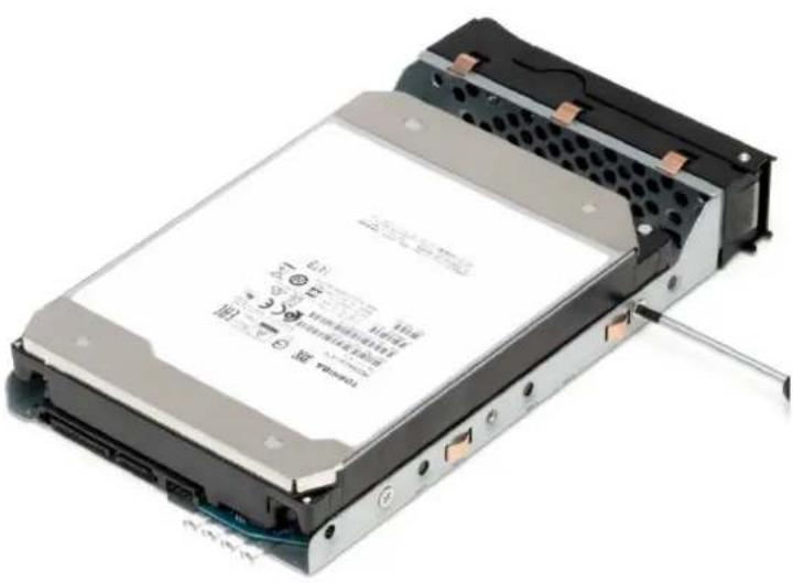
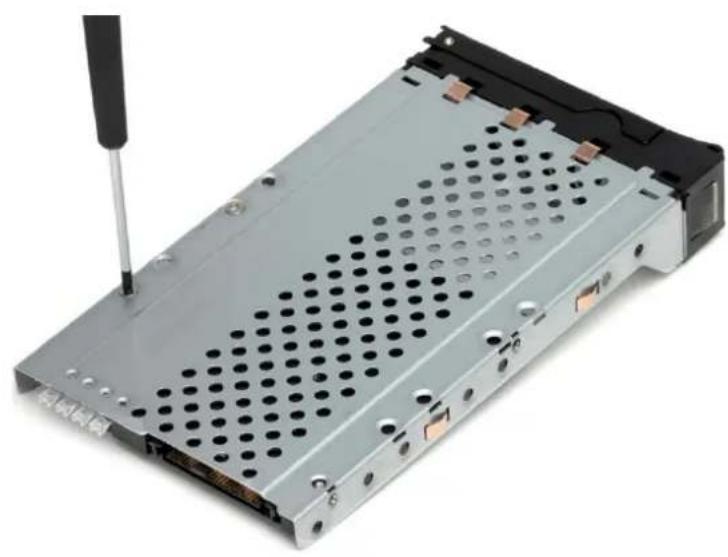
Hand inserting a black remote control into a black rack device (no text or symbols visible)- Remove the screws securing the drive from the drive tray.
NOTE : 2.5-inch drives have screws installed on the bottom of the drive tray. They are also installed with a spacer. The spacer will need to be removed and secured to use with the new drive installation.
3.5-Inch Drive
natural_image
Exterior view of a computer hard drive chassis with visible internal components and mounting bracket (no text or symbols)2.5-Inch Drive
natural_image
Close-up of a computer drive chassis with a screwdriver inserted, showing internal components and mounting holes (no text or symbols visible)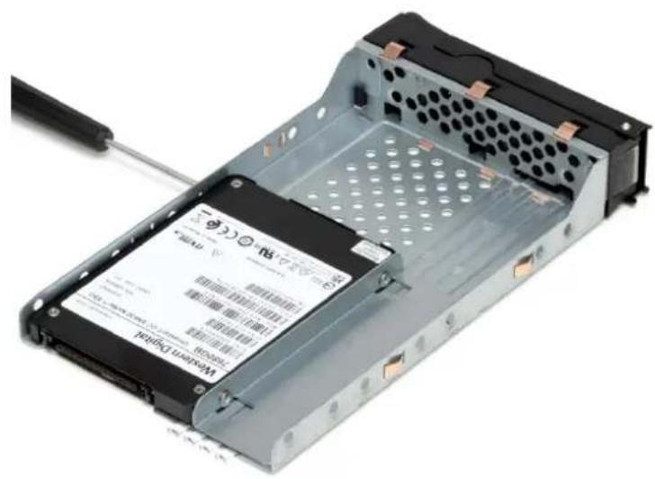
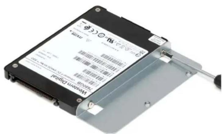
- Remove the drive and place a new drive into the drive tray with the label facing upwards. Secure the drive to the drive tray.
NOTE : 2.5-inch drives will need to be installed with a spacer and secured on the bottom of the drive tray.
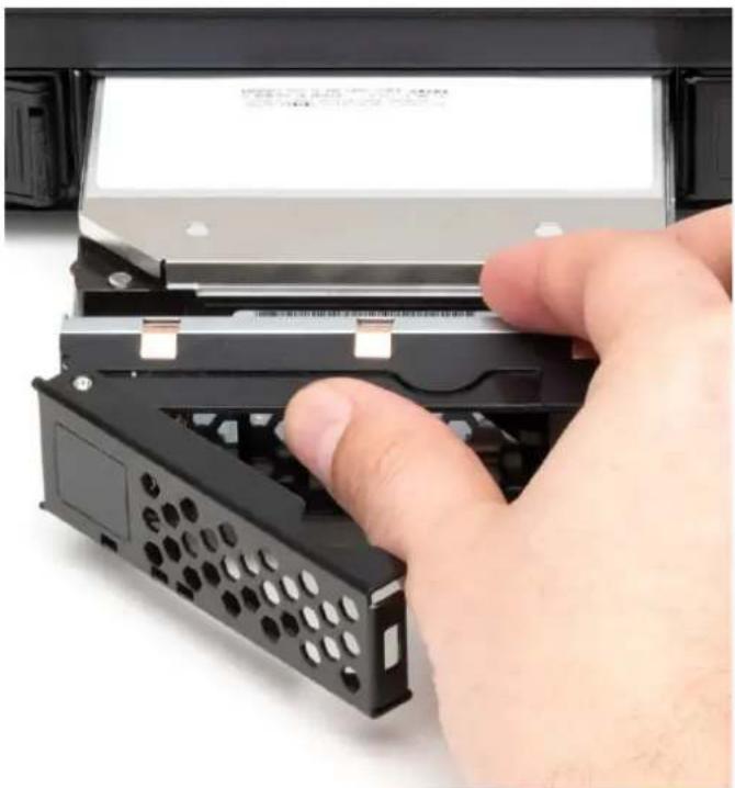
- Insert the drives, with the drive label facing upwards. Carefully push the drive tray forward into the drive bay. Do not force the drive as a minimal amount is needed. The drive will rest slightly protruded outside the drive bay.
NOTE : The drive trays have locking mechanisms. Ensure the locks are not engaged before installing the drive trays. The lock is disengaged when the locking mechanism is in the up position.
natural_image
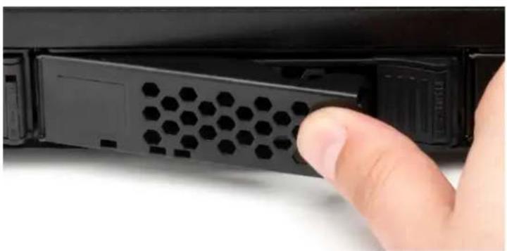
Hand inserting a remote control into a device (no visible text or symbols)- Press the drive tray door to finish pushing the drive into the drive bay and completing the connection.
natural_image
Close-up of a hand inserting a hexagonal socket into a black device casing (no text or symbols visible)2.4 Power Supply Failure & Replacement
The OWC Jupiter Kore has redundant, hot-swappable power supplies which can withstand a failure of one power supply module.
OWC Jupiter Kore 16-Bay (3U) : 875W 1+1 redundant, hot-swappable, and load-balancing power supply with active PFC
OWC Jupiter Kore 8-Bay (2U) : 650W high-efficiency 1+1 redundant 90\~264 VAC full-range, auto-switching power supply
While all of the power supply modules are healthy, the power load is automatically balanced across them. In the event of a power supply failure, an alarm will sound and the 'Power' LED on the front of the unit will turn solid red. Please complete the following instructions to replace a failed power supply module.
OWC Jupiter Callisto 16-Bay (3U)
Removing Failed Power Supply
-
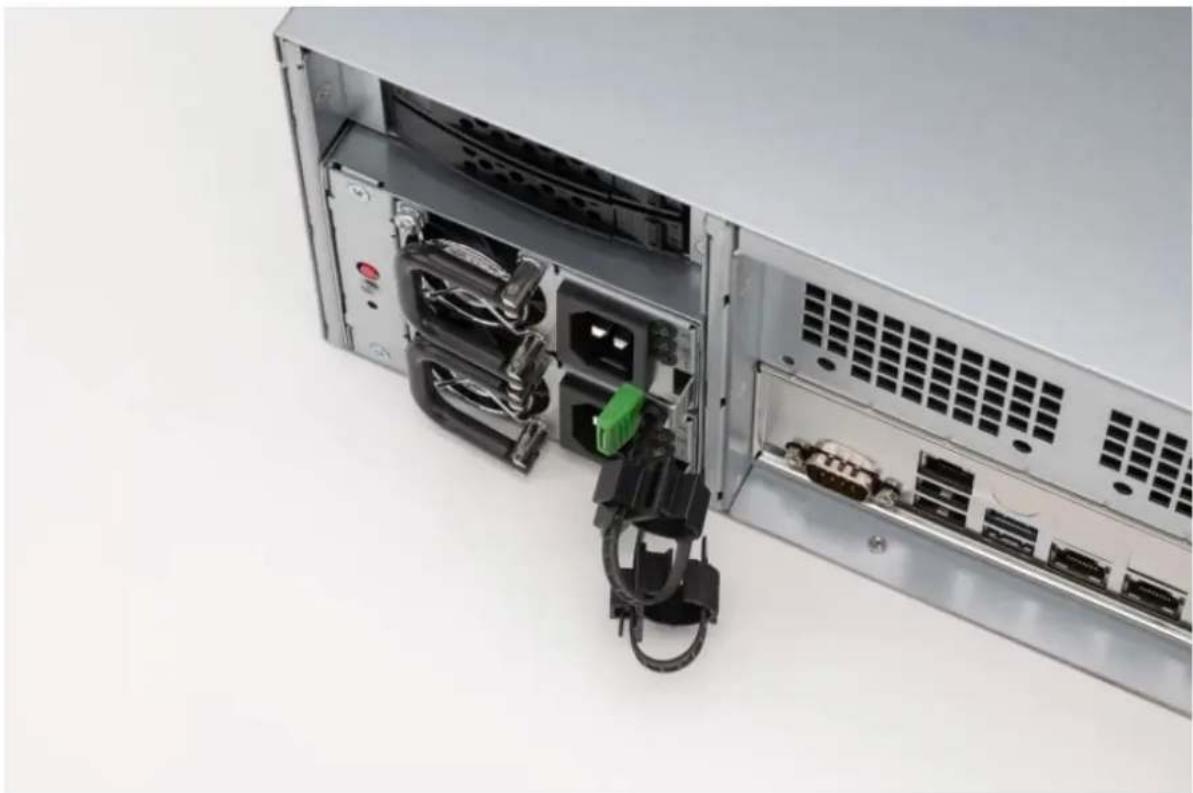
Identify the failed power supply. The LED on the failed power supply will be illuminated red.
-
Lift and brace a finger against the power supply handle and press the lever to the left.
natural_image
Interior view of a server rack with visible internal components and ventilation grilles (no text or symbols)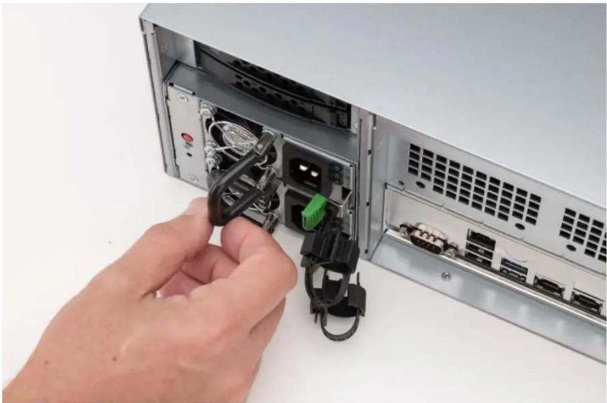
natural_image
Close-up of hands inserting cables into a server rack (no visible text or labels)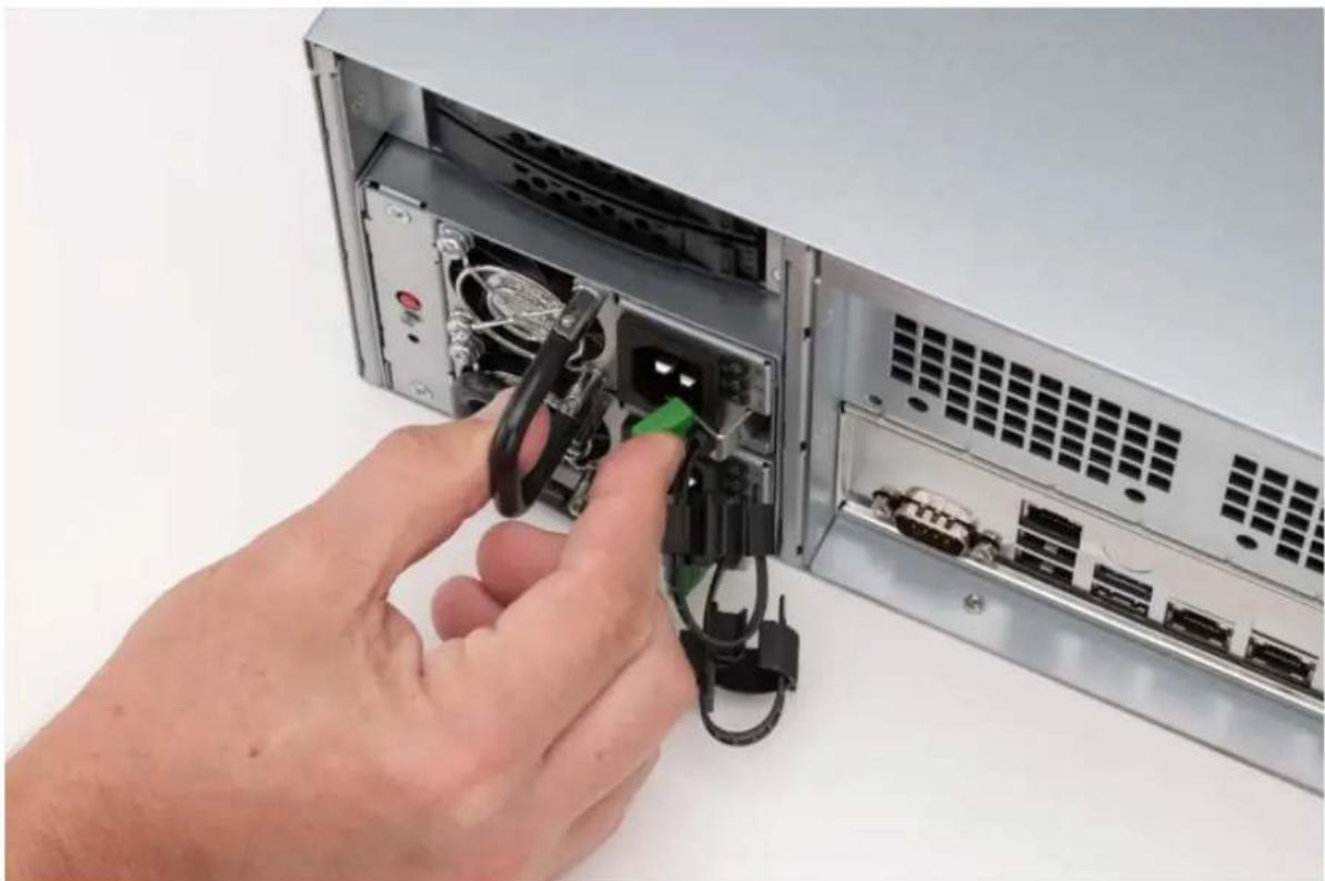
natural_image
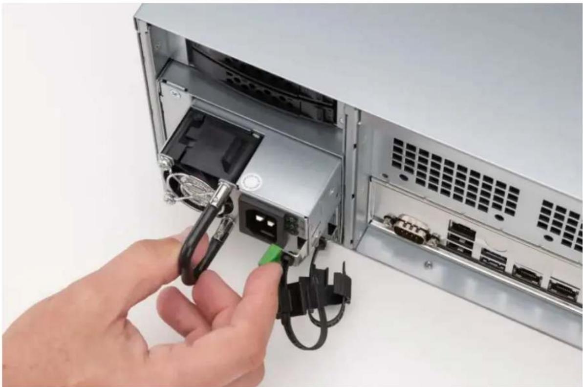
Close-up of hands inserting cables into a server rack with visible ports and connectors (no text or symbols)- Disengage the failed power supply by pulling out while pressing the lever.
natural_image
Close-up of hands inserting a USB cable into an open computer drive chassis (no text or symbols visible)- Carefully remove the failed power supply. The lever no longer needs to be pressed once the power supply is slightly disengaged from the OWC Jupiter Kore.
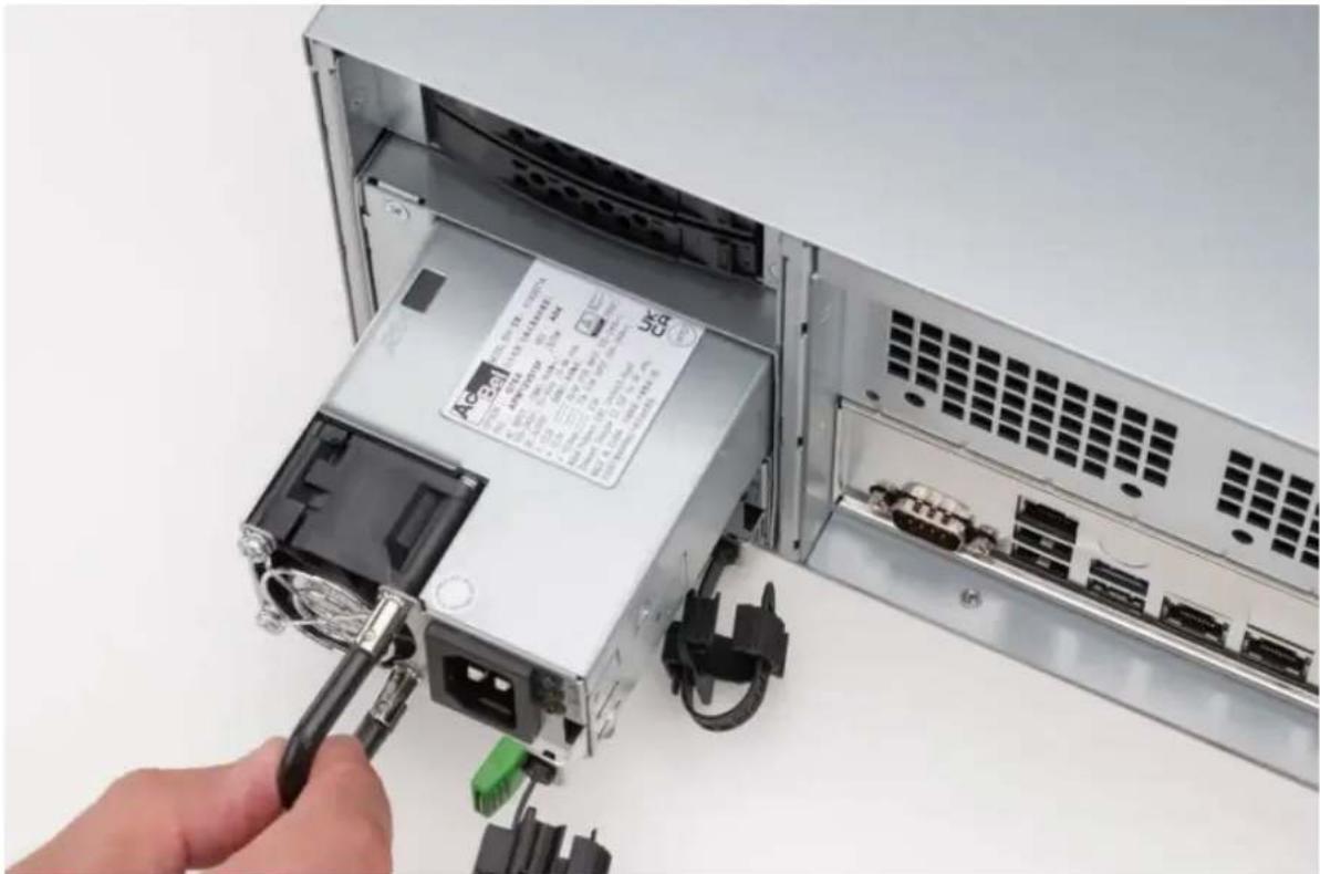
natural_image
Close-up of a computer power adapter with cable inserted, showing internal components and a hand holding the charger (no visible text or symbols)Installing New Power Supply
- Insert the new power supply. Ensure the connections are located on the right, the release tab is on the right, and the power supply cable connection is on the right.
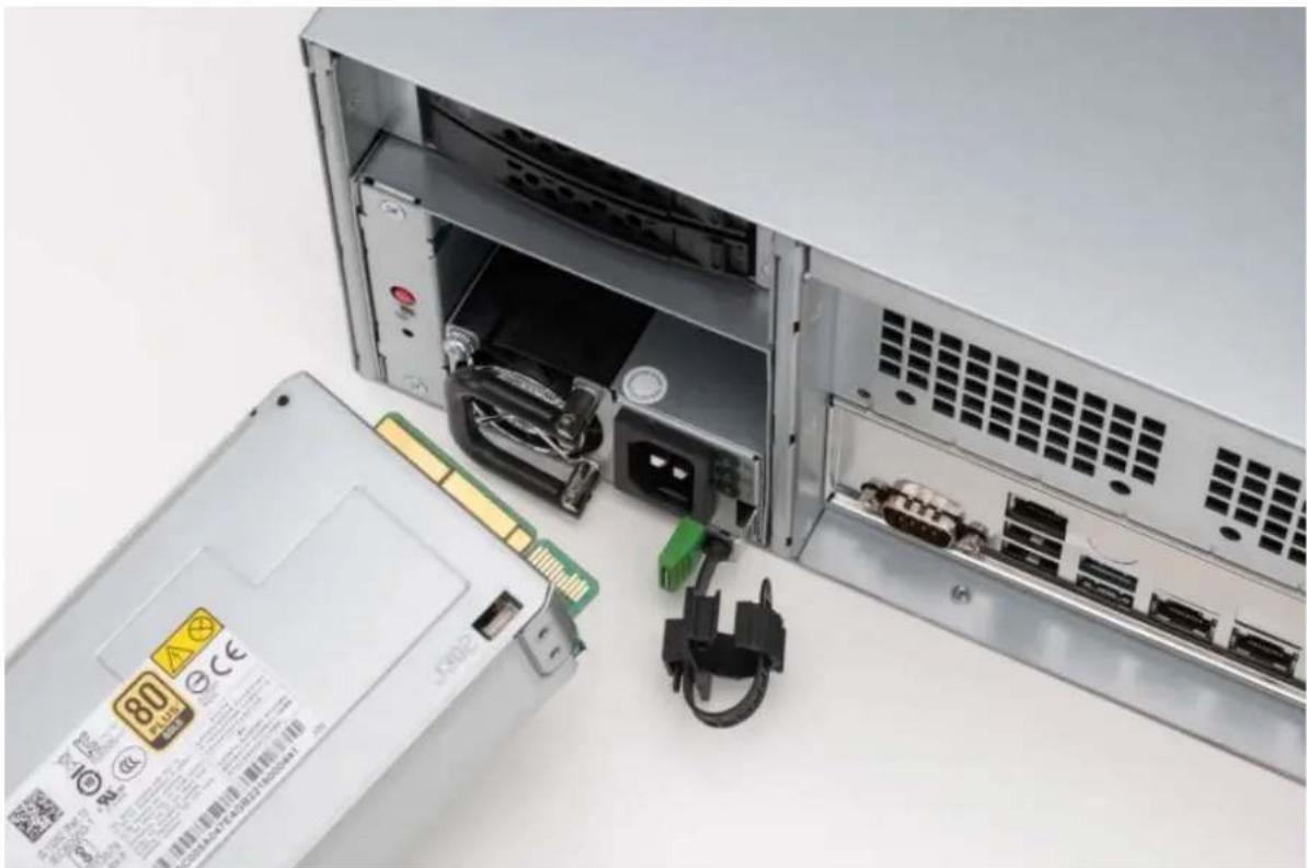
natural_image
Computer hardware unit with open rear panel and internal components, no visible text or symbols on main subject- Carefully slide the power supply into the OWC Jupiter Kore until fully seated. A click will be heard as the lever locks into position.
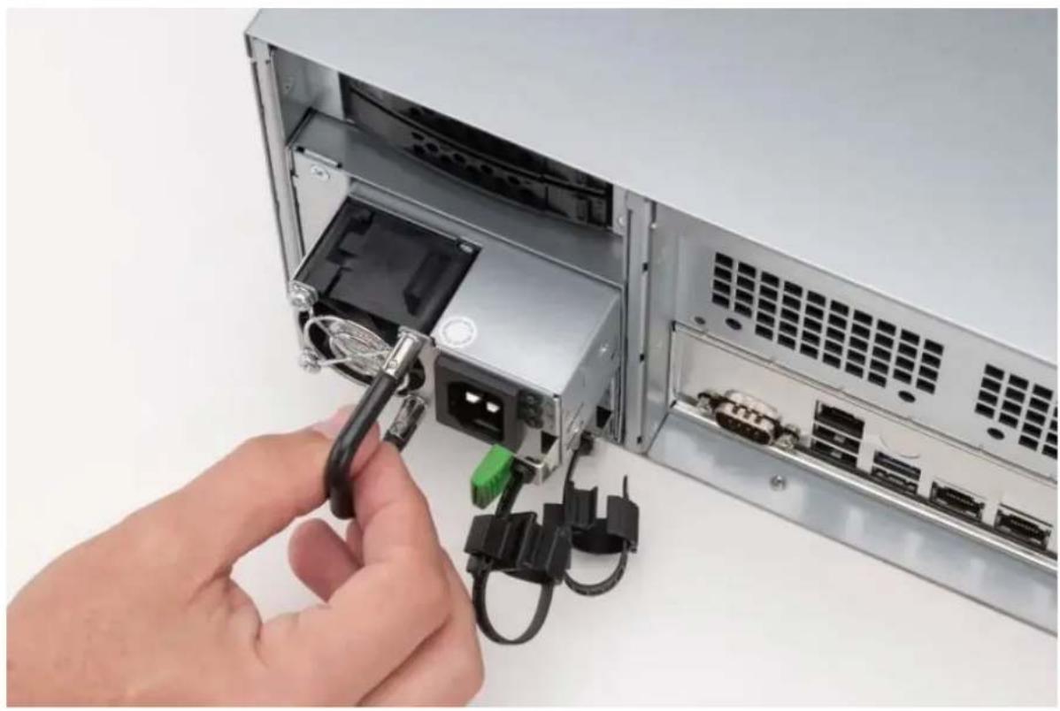
natural_image
Hand inserting a USB cable into an open computer drive chassis (no text or symbols visible)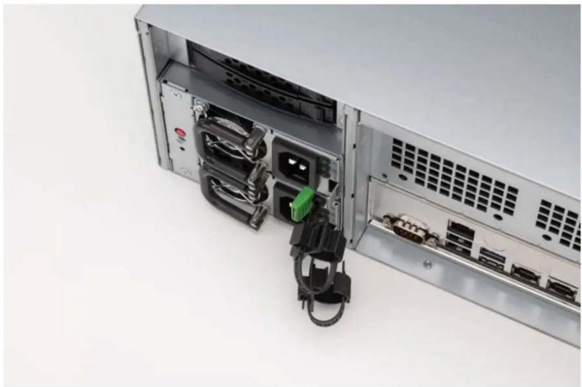
natural_image
Interior view of a server rack with exposed internal components and connectors (no visible text or labels)OWC Jupiter Callisto 8-Bay (2U)
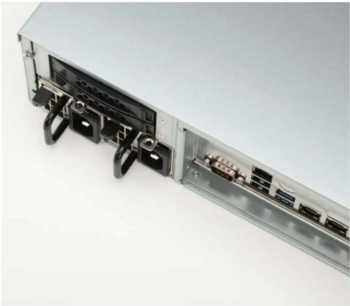
Removing Failed Power Supply
- Identify the failed power supply. The LED on the failed power supply will be illuminated red.
- Brace a finger against the power supply handle and press the lever to the right.
natural_image
Cross-sectional view of a computer monitor case showing internal components (no text or symbols visible)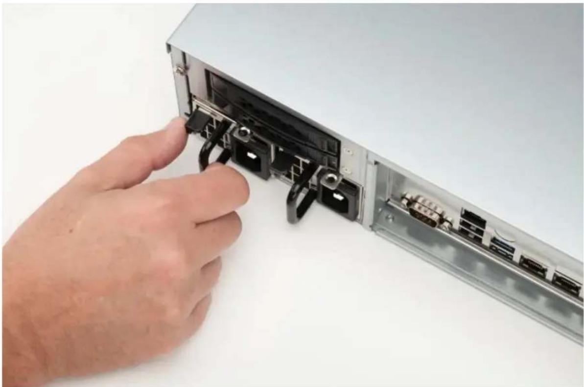
natural_image
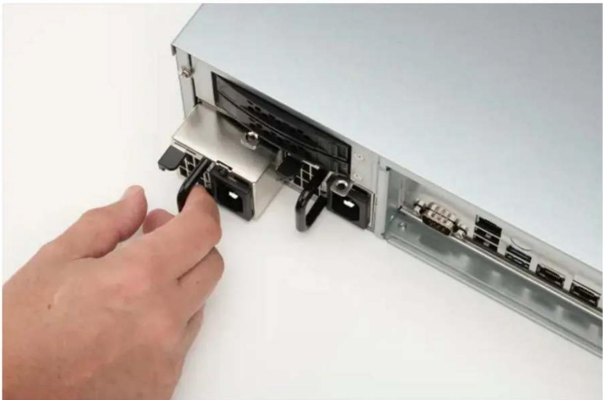
Hand inserting a USB into a server rack with multiple ports (no visible text or labels)- Disengage the failed power supply by pulling out while pressing the lever.
natural_image
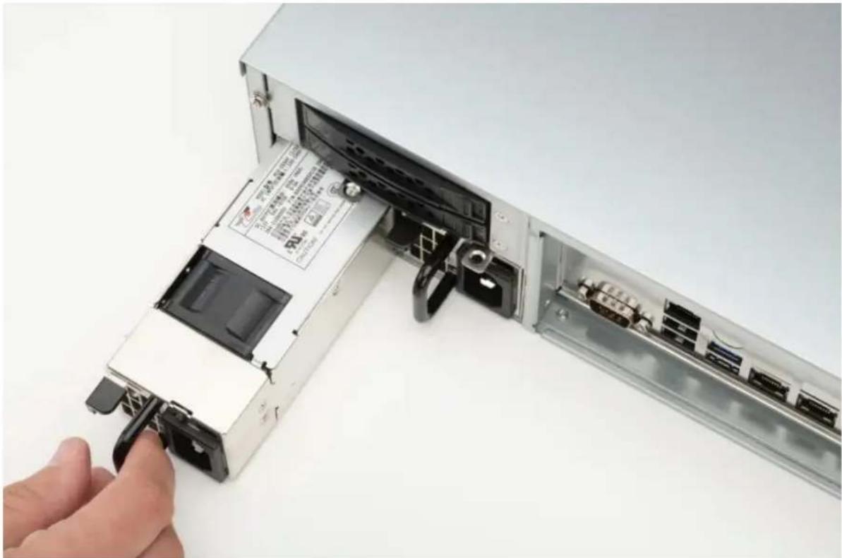
Hand inserting a USB into a computer drive module (no text or symbols visible)- Carefully remove the failed power supply. The lever no longer needs to be pressed once the power supply is slightly disengaged from the OWC Jupiter Kore.
natural_image
Close-up of a computer drive showing internal components and a hand inserting a cable (no visible text or symbols)Installing New Power Supply
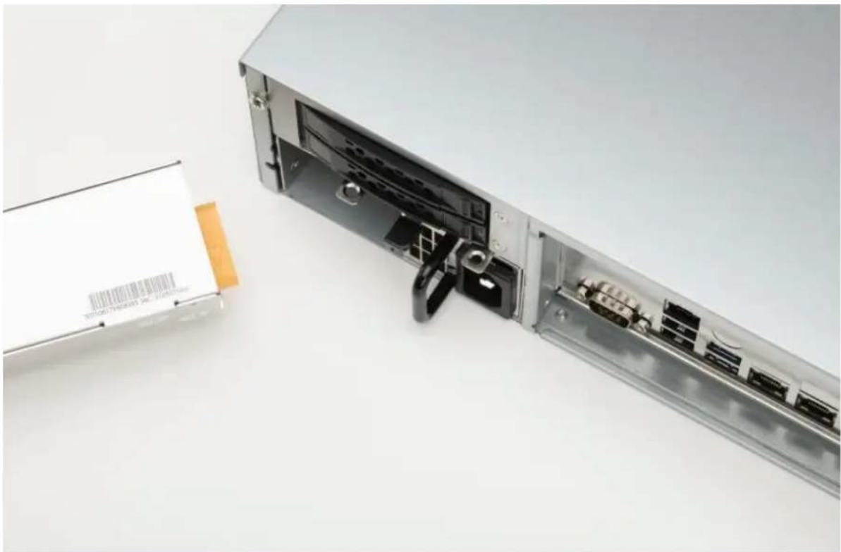
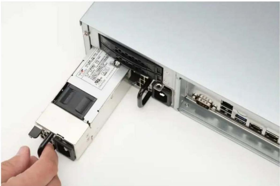
- Insert the new power supply. Ensure the connection is located in the top-right, the release tab is on the left, and the power supply cable connection is on the right.
natural_image
Exterior view of a computer drive unit with internal components and a separate rectangular package (no visible text or symbols)- Carefully slide the power supply into the OWC Jupiter Kore until fully seated. A click will be heard as the lever locks into position.
natural_image
Close-up of a computer drive showing internal components and a hand inserting a cable (no visible text or symbols)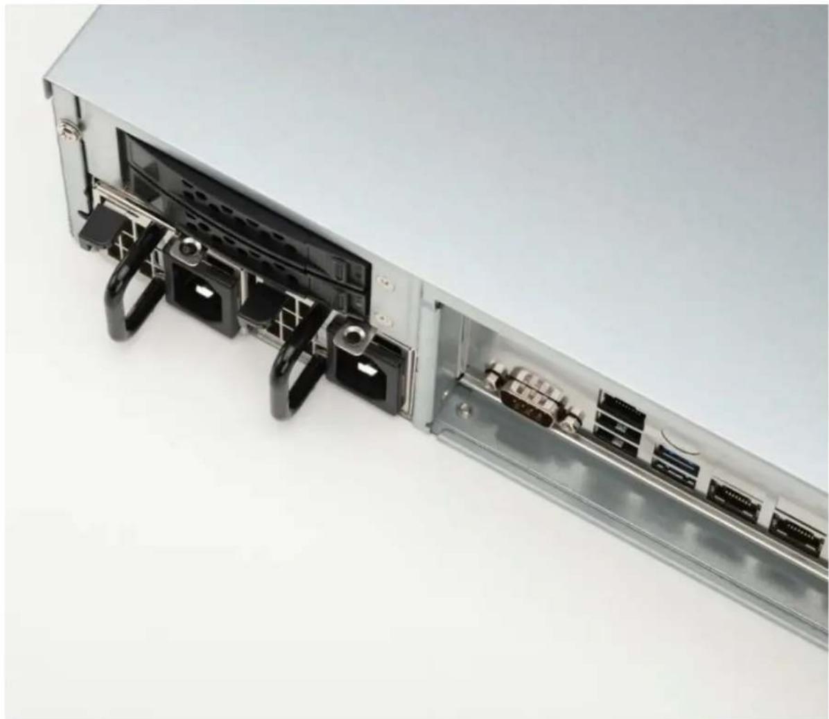
natural_image
Internal view of a computer drive showing internal components and ports (no text or symbols visible)Device Setup
3.1 Connection
This section describes the process of connecting an OWC Jupiter Kore expansion to the OWC Jupiter Callisto.
NOTE : The OWC Jupiter Callisto is a separately sold and will require installation setup before being connected to an OWC Jupiter Kore. Please consult the OWC Jupiter Callisto Support Guide page for more information.
-
Plug the power cable into the OWC Jupiter Kore power port located on the back. Connect the other end into a power outlet. The Power LED will illuminate a solid green.
NOTE : We recommend using a battery backup unit to help protect from data loss due to electrical anomalies.
NOTE : The power supply is an autosensing unit and will automatically determine your AC source voltage level. -
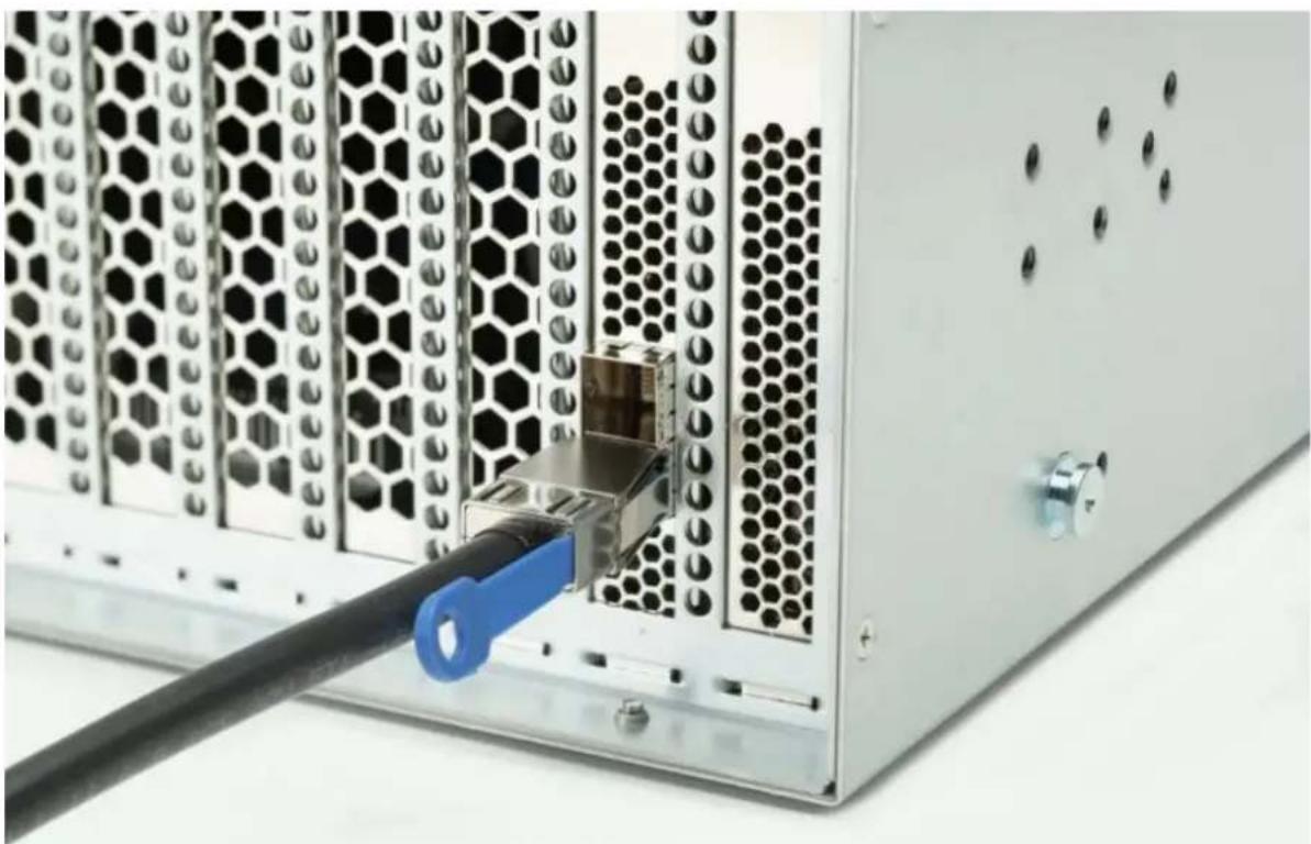
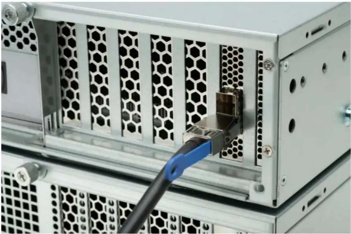
Connect a Mini SAS HD SFF 8644 cable into one of the Mini SAS HD SFF 8644 ports located on the back of the OWC Jupiter Callisto. Ensure the blue tab on the cable is positioned to the right.
natural_image
Close-up of a server rack with a black cable inserted into the socket, showing network patterns and ventilation (no text or symbols visible)- Connect a Mini SAS HD SFF 8644 cable into one of the Mini SAS HD SFF 8644 ports located on the back of the OWC Jupiter Kore. Ensure the blue tab on the cable is positioned to the right.
natural_image
Close-up of a server rack with hexagonal ventilation grilles and a blue cable inserted into a socket (no visible text or symbols)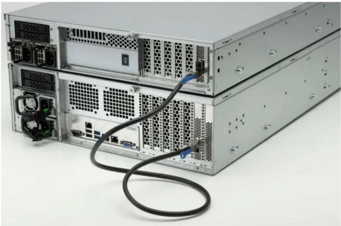
natural_image
Stacked server rack with attached cable, showing ports and connectors (no visible text or labels)- The additional storage offered by the OWC Jupiter Kore can be accessed through the TrueNAS SCALE Dashboard under the Storage category.
3.2 TrueNAS SCALE Dashboard
This section describes the process of accessing the UI to manage the OWC Jupiter Callisto.
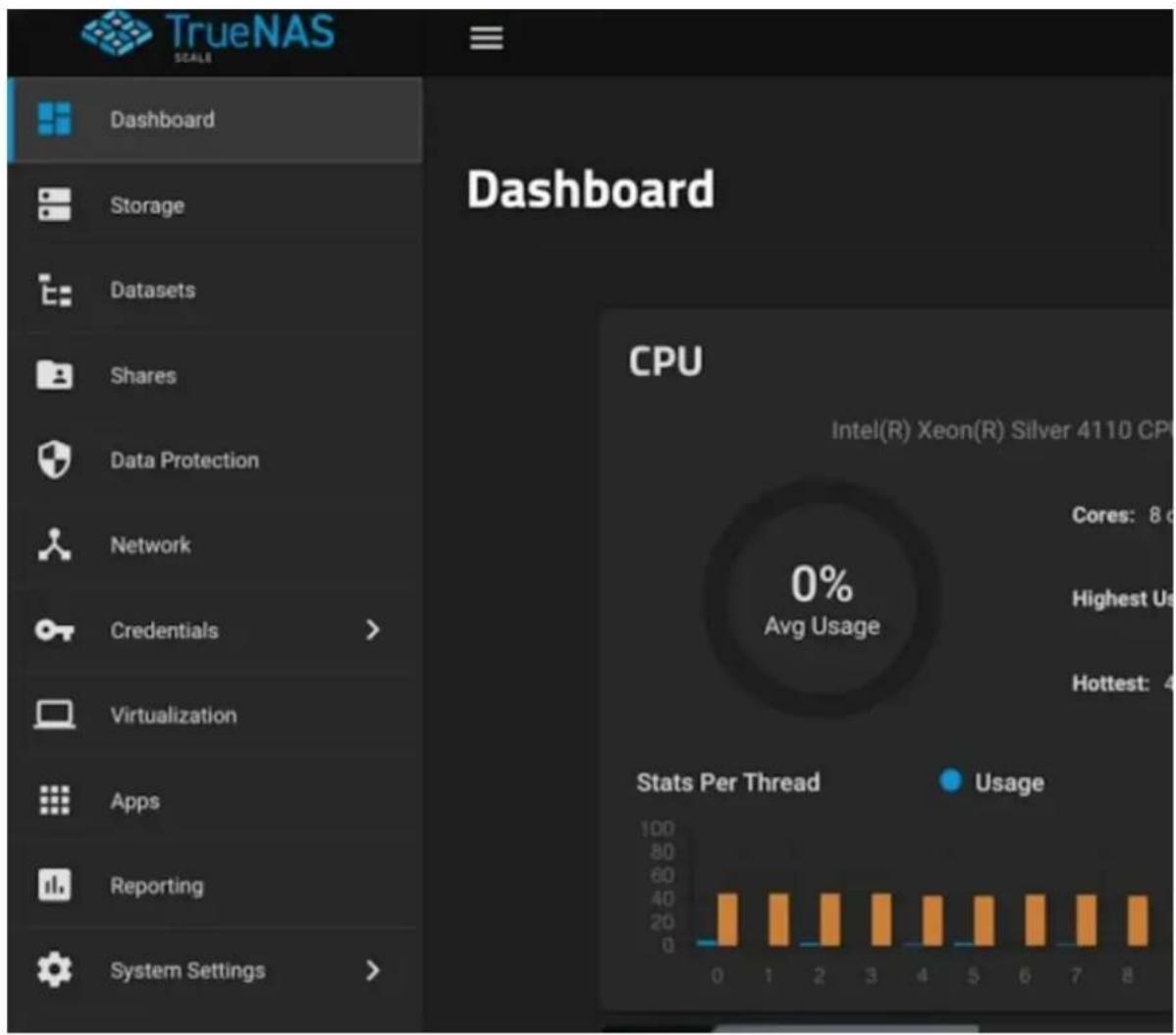
- Open a web browser of your choice and type in the address bar the device's DHCP IP address (ex. 172.21.124.254) or the device's Static IP address (ex. 192.168.0.10) and press "Enter". A login screen for TrueNAS SCALE should appear. Enter the login credentials:
Username : admin
Password : jupiter

- Once you log in this will be the dashboard view.
- More information regarding the use of TrueNAS SCALE can be reviewed by visiting TrueNAS's online guide:https://www.truenas.com/docs/scale/gettingstarted/
Device Management
4.1 Drive Failure
This section describes the process of replacing a failed drive.
- Physically replace the failed drive as covered in section 2.3 "Drive Installation & Removal".
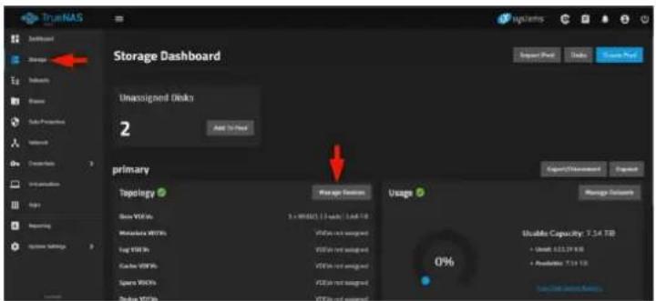
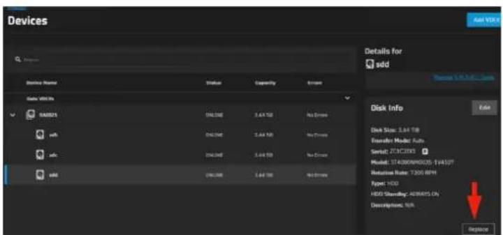
- Access the TrueNAS SCALE web interface. Navigate to Storage and select Manage Devices.
- Expand the list of "Data VDEVs" and locate the disk desired for replacement. Click on the drive and select "Replace".
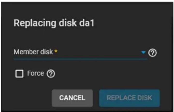
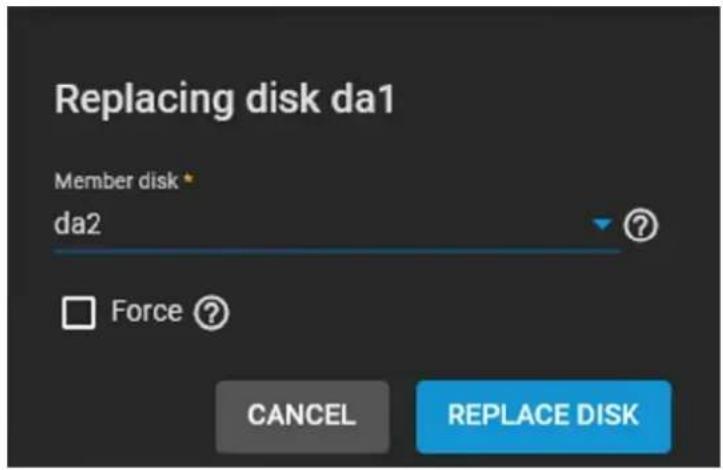
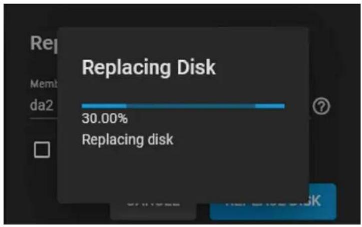
- A Replacing disk window will appear. Drop the Member disk list and select the new replacement drive. Click Replace Disk to finalize the rebuild with the new drive.
4.2 Usage Notes
- The USB ports of the OWC Jupiter Kore are not intended for data mounting purposes. Direct/local system updating and mouse/keyboard are the intended supports.
- While the OWC Jupiter Kore allows remote connectivity through open technologies such as OpenVPN and commercial offerings such as ZeroTier, the installation, configuration, and support are provided by the customer's local IT/Network team or the 3rd party developer.
Support Resources
5.1 Troubleshooting
• Networking Issues
- Make sure Drivers are installed if needed for Client machines. This would be apparent if an Adapter or NIC card didn't show on the Client machine for configuration.
- Check Patch Cables, swap out cable with known good one.
- Double check IP address on Server/Client. Make sure they are on the same IP range and Subnet. (Static IP: 192.168.0.010/ 255.255.255.0, DHCP IP: 172.27.x.x/ 255.255.255.0)
- Swap out Adapters on Client machine (MacBookPro / MacBookAir / Windows PC)
- Plug in monitor to check if the OS is reporting an issue via Shell.
• Double check Jumbo Frames on Server/Client. - Check Link speed of hardware on Client NIC. May need to Manually set 10G speeds or higher depending on the NIC in question.
• Share Issues
- Double check all IP addresses involved with testing the Share. Check Both the Server and Client.
- Check Permissions on the dataset.
- Check Share path to make sure it is set appropriately.
• Double check Jumbo Frames on both Server and Client. - Delete and recreate Share if necessary.
• Refer to Configuration Guide for details on above Troubleshooting steps.
5.2 About Data Backup
- Any data loss or corruption while using the OWC Jupiter Kore is the sole responsibility of the user, and under no circumstances may OWC, its parents, partners, affiliates, officers, employees, or agents be held liable for loss of the use of data including compensation of any kind or recovery of the data.
5.3 Contacting Support
- Phone : M–F, 9am–6pm CT USA 1-866-692-7100 |INTL +1-815-338-4751
- Chat : M–F, 8am–8pm, Sat 9am–5pm CT (www.owc.com/support)
- Email : Answered within 48 hours (www.owc.com/support) OWC Jupiter Kore Support Guide Page
Terms & Conditions of Sale
Warranty
OWC's products are subject to OWC's Terms & Conditions of Sale located at Terms of Sale or other applicable terms. The OWC Jupiter Kore comes with a 3-Year Limited Warranty Additional warranty information can be viewed by visiting Hardware Warranties
Changes
The material in this document is for information purposes only and subject to change without notice. While reasonable efforts have been made in the preparation of this document to assure its accuracy, OWC, its parent, partners, affiliates, officers, employees, and agents assume no liability resulting from errors or omissions in this document, or from the use of the information contained herein. OWC reserves the right to make changes or revisions to the product design or the product manual without reservation and without obligation to notify any person of such revisions and changes.
FCC Statement
Warning ! Modifications not authorized by the manufacturer may avoid the user's authority to operate this device.
NOTE : This equipment has been tested and found to comply with the limits for a Class B digital device, pursuant to Part 15 of the FCC Rules. These limits are designed to provide reasonable protection against harmful interference in a residential installation. This equipment generates, uses and can radiate radio frequency energy and, if not installed and used in accordance with the instructions, may cause harmful interference to radio communications. However, there is no guarantee that interference will not occur in a particular installation. If this equipment does cause harmful interference with radio or television reception, which can be determined by turning the equipment off and on, the user is encouraged to try to correct the interference by one or more of the following measures:
- Reorient or relocate the receiving antenna.
- Increase the separation between the equipment and receiver.
- Connect the equipment to an outlet on a circuit different from that to which the receiver is connected.
Copyrights and Trademarks
No part of this publication may be reproduced, stored in a retrieval system, or transmitted in any form or by any means, electronic, mechanical, photocopying, recording or otherwise, without the prior written consent of OWC.
2023 Other World Computing, Inc. All rights reserved. OWC and the OWC logo are trademarks of New Concepts Development Corporation, registered in the U.S. and/or other countries. OWC Jupiter Kore is trademark of New Concepts Development Corporation. Mac and macOS are trademarks of Apple Inc., registered in the U.S. and other countries. Thunderbolt and the Thunderbolt logo are trademarks of Intel Corporation in the U.S. and/or other countries. Other marks may be the trademark or registered trademark property of their owners.
- Introduction
- System Requirements
- Hardware
- Supported Drives
- Package Contents
- OWC Jupiter Kore 16-Bay (3U)
- OWC Jupiter Kore 8-Bay (2U)
- About This Manual
- General Use Precautions
- Safety Precautions
- Front View
- Rear View
- Side View
- Rail Installation
- Rack Installation & Removal
- Rack Installation
- Rack Removal
- Drive Installation & Removal
- Drive Installation
- Drive Removal & Replacement
- 3.5-Inch Drive
- 2.5-Inch Drive
- Power Supply Failure & Replacement
- OWC Jupiter Callisto 16-Bay (3U)
- Removing Failed Power Supply
- Installing New Power Supply
- Device Setup
- Connection
- TrueNAS SCALE Dashboard
- Device Management
- Drive Failure
- Usage Notes
- Support Resources
- Troubleshooting
- • Networking Issues
- • Share Issues
- About Data Backup
- Contacting Support
- Terms & Conditions of Sale
- Warranty
- Changes
- FCC Statement
- Copyrights and Trademarks
Brand : OWC
Model : Jupiter Kore
Category : Server