USER MANUAL LVM-246A TVLogic
24" Full HD Professional LCD Monitor
Operation manual_V1.2
natural_image
Top-down architectural sketch of a rectangular electronic device with internal components and mounting holes (no text or symbols)
natural_image
Digital TV displaying a white daisy flower against a blue sky background (no text or symbols visible)
TVlogic®
FCC (Federal Communications Commission)
This equipment has been tested and found to comply with the limits for class A digital device, pursuant to part 15 of the FCC Rules. These limits are designed to provide reasonable protection against harmful interface when the equipment is operated in a commercial environment.
This equipment generates, uses and can radiate radio frequency energy and if not installed and used in accordance with the instruction manual, may cause harmful interference to radio communications.
Operation of this equipment in a residential to correct the interference at his own expense
CAUTION: Change or modifications not expressly approved by the manufacturer responsible for compliance could void the
user's authority to operate the equipment.
Disposal of Old Electrical & Electronic Equipment
(Applicable in the European Union and other European countries with separate collection systems) This symbol on the product or on its packing indicates that this product shall not be treated as household waste.
Instead it shall be handed over to the applicable collection point for the recycling of electrical and electronic equipment.
By ensuring this product is disposed of correctly, you will help prevent potential negative consequence for the environment and human health, which could otherwise be caused by inappropriate waste handling of this product. The recycling of materials will help to conserve natural resources.
Contents
01 CAUTION 04p
02 MAIN FEATURES 07p
03 CONTROLS & FUNCTIONS 08p
04 MENU ORGANIZATION & ADJUSTMENT 13p
[7] DISPLAY & SET 27p
06 FIRMWARE UPGRADE 30p
07 BUTTON FUNCTIONS 31p
08 OTHER FUNCTIONS 34p
09 DVI / HDMI SUPPORT RESOLUTION 41p
10 PRODUCT SPECIFICATIONS 42p
11 OPTIONAL ACCESSORIES 43p
01 CAUTION
• Always use set voltage.
- AC : 100 - 240V (0.6\~0.4A, 50/60Hz)
-
DC : 12 - 24V (MAX 3.5A - 2A)
-
All operating instructions must be read and understood before the product is operated.
• These safety and operating instructions must be kept in safe place for future reference.
- All warnings on the product and in the instructions must be observed closely.
- All operating instructions must be followed.
- Do not use attachments not recommended by the manufacturer. Use of inadequate attachments can result in accidents.
- This product must be operated on a power source specified on the specification label. If you are not sure of the type of power supply used in your home, consult your dealer or local power company. For units designed to operate on batteries or another power source, refer to the operating instructions.
- The power cords must be routed properly to prevent people from stepping on them or objects from resting on them. Check the cords at the plugs and product.
- In case of using other DC 12V/24V adapters instead of the standard adapter provided by the manufacturer, please check the proper load capacity (or current capacity) and use an adapter with stable voltage.
-
Do not overload AC outlets or extension cords. Overloading can cause fire or electric shock.
-
Never insert an object into the product through vents or openings. High voltage flows in the product, and inserting an object can cause electric shock and/or short internal parts. For the same reason, do not spill water or liquid on the product.
- Do not attempt to service the product yourself. Removing covers can expose you to high voltage and other dangerous conditions. Request a qualified service person to perform servicing.
- If any of the following conditions occurs, unplug the power cord from the AC outlet, and request a qualified service person to perform repairs.
a. When the power cord or plug in damaged.
b. When a liquid was spilled on the product or when objects have fallen into the product.
c. When the product has been exposed to rain or water.
d. When the product does not operate properly as described in the operating instructions.
Do not touch the controls other than those described in the operating instructions. Improper adjustment of controls not described in the instructions can cause damage, which often requires extensive adjustment work by a qualified technician.
e. When the product has been dropped or damaged.
f. When the product displays an abnormal condition. Any noticeable abnormality in the product indicates that the product needs servicing.
• In case the product needs replacement parts, make sure that the service person uses replacement parts specified by the manufacturer, or those with the same characteristics and performance as the original parts. Use of unauthorized parts can result in fire, electric shock and/or other danger.
01 CAUTION
- Upon completion of service or repair work, request the service technician to perform safety checks to ensure that the product is in proper operating condition.
- When mounting the product on a wall or ceiling, be sure to install the product according to the method recommended by the manufacturer.
- Unplug the power cord from the AC outlet before cleaning the product. Use a damp cloth to clean the product. Do not use liquid cleaners or aerosol cleaners.
- Unplug the power cord from the AC outlet if you do not use the product for considerably long time.
- Do not use the product near water, such as bathtub, washbasin, kitchen sink and laundry tub, swimming pool and in a wet basement.
- Keep the product away from direct rays of the Sun-light.
- Do not place the product on an unstable cart, stand, tripod or table. Placing the product on an unstable base can cause the product to fall, resulting in serious personal injuries as well as damage to the product. Use only a cart, stand, tripod, bracket or table recommended by the manufacturer or sold with the product. When mounting the product on a wall, be sure to follow the manufacturer's instruction. Use only the mounting hardware recommended by the manufacturer.
-
When relocating the product placed on a cart, it must be moved with the utmost care. Sudden stops, excessive force and uneven floor surface can cause the product to fall from the cart.
-
The vents and other openings in the cabinet are designed for ventilation. Do not cover or block these vents and openings since insufficient ventilation can cause overheating and/or shorten the life of the product. Do not place the product on a bed, sofa, rug or other similar surface, since they can block ventilation openings. This product is not designed for built-in installation; do not place the product in an enclosed place such as a bookcase or rack, unless proper ventilation is provided or the manufacturer's instructions are followed.
- The LCD panel used in this product is made of glass. Therefore, it can break when the product is dropped or applied with impact. Be careful not to be injured by broken glass pieces in case the LCD panel breaks.
- Keep the product away from heat sources such as radiators, heaters, stoves and other heat generating products (including amplifiers).
- Infrared devices can cause noise or malfunction under condition as below.
a. parts of the body come into contact with the infrared transmitter or acoustic device.
b. Obstacles can cause electrical changes if there is a partition in the middle or in the wall.
c. Exposure to radio interference from medical equipment, microwave ovens, wireless LAN devices, etc. with the same frequency band.
- If the still image is displayed on the screen in the same position for a long period of time, the permanent burn-in on the LCD panel may occur.
So, do not display characters or markers continuously.
If the video signals or image patterns are continuously displayed at the maximum or high level of luminance, the image smearing or flicker may occur on the screen because of the LCD panel's structure and characteristics of materials used.
When the permanent burn-in, image smearing, or other damages happen on the LCD panel due to the improper use by the end user, the warranty service is not applied.
01 CAUTION
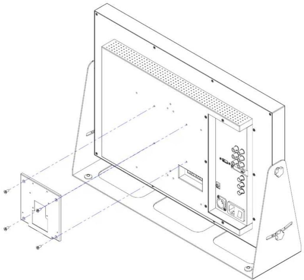
VESA WALL MOUNTING
natural_image
Technical line drawing of a modular electronic device with internal components and mounting brackets (no text or symbols)
- When mounting on the wall bracket, fix the monitor using 4 pieces of M4 x 10mm screws.
- Use the 100mm x 100mm VESA MOUNTING holes on the rear housing.
- Do not install on a place other than a vertical wall.
- Do not use screws longer then the standard dimension, as they may cause damage to the inside to the monitor.
- Do not tighten the screws too much. It may damage the monitor or make the monitor fall and cause personal injury. Vidente(TVLogic) is not liable for these kinds of accidents.
- Remove the stand before installing the monitor on the wall using the wall mount kit.
- Do not install your wall mount kit while the monitor is plugged in.
It may result in personal injury due to electric shock.
02 MAIN FEATURES
LVM-246A(-N1) Monitors contain the following features:
- Compatible with varied SDI signals
- The product is compatible with varied SD/HD/3G(A/B)-SDI 480i,576i,720p,1080i/p,1080psf.
- Compatible with analog signals
- The product is compatible with analog signals : Component, S-Video, Composite
- HDMI, DVI digital/analog(VGA) input is available without any other accessories.
- All-in-one type system
- Slim and all-in-one type monitor that requires no other accessories and optimized for space utilization.
- Waveform & Vector Scope support.
- Luma(Y') zone check support. (False color)
- Embedded Audio Level Meter support.
- Luma(Y') zone check(Color/Zebra type)/Range error function
- Audio in & out
- built-in internal speaker. (Embedded audio & External audio in)
- Stereo audio out using phone jack & external audio in.
- Knob Control
- Easy to adjust user configuration using the control knobs.
• BLUE ONLY/MONO/Focus-Assist/H/V delay
- Internal pattern generator(0\~100% Gray/Colorbar+Pluge)
• Varied Markers & Safety Areas
- Center Marker, Safety Area Marker, Aspect Marker, Display Size(Scan).
• 1:1 SCAN / Zoom
- Outputs the original signal image on the screen without scaling.
- Outputs the original signal image with zoom-in.
- Zoom scroll function. (left/right/up/down)
- AC/DC Compatible
- Basically, this product is powered by a normal AC source, and is also compatible with DC 12V \~24V
- Remote control function
- The product can be remotely controlled using external switch or RS-422 communication.
• RS422/UMD feature support
- This product supports protocols provided by TVLogic or a TSL protocol.
• Additional Features
- Wide Viewing Angle, Loop Through (SDI/Analog), VESA mounting, Easy to operate OSD user interface, Rack Mountable Design. High Brightness 600nits
03 CONTROLS & FUNCTIONS
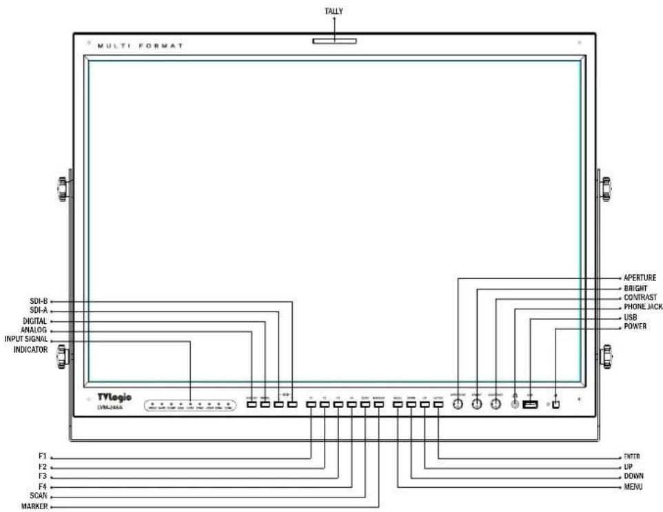
LVM-246A(-N1): FRONT
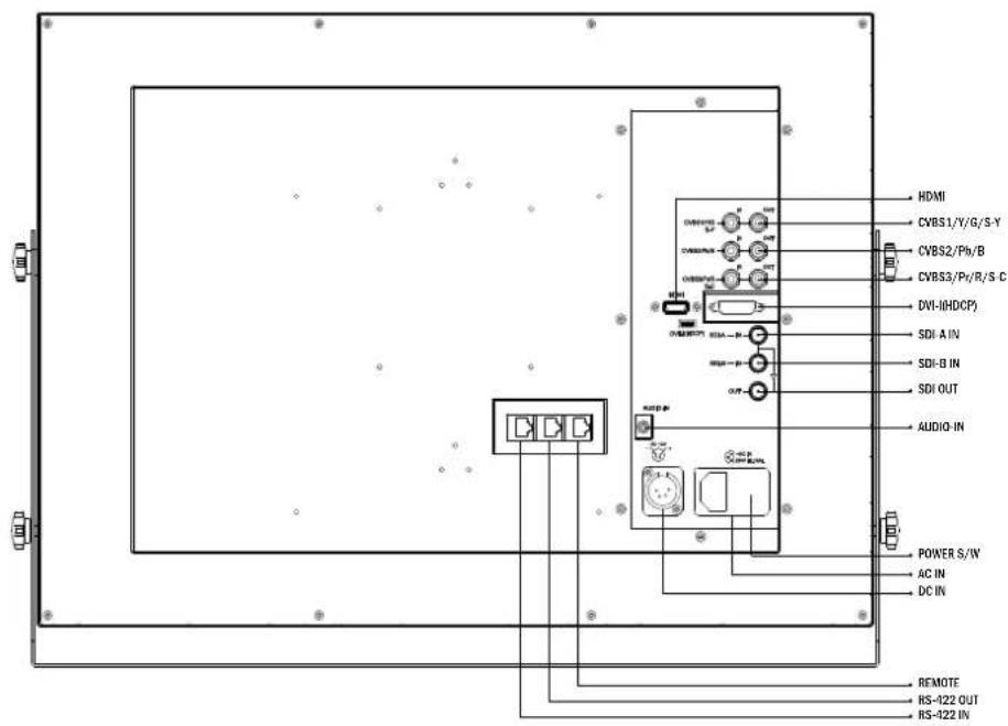
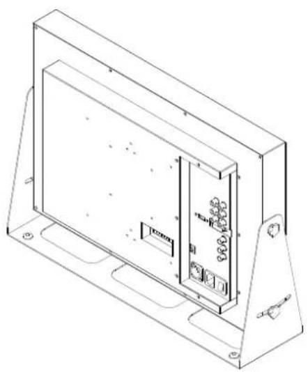
LVM-246A(-N1): REAR
03 CONTROLS & FUNCTIONS
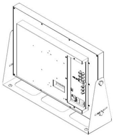
LVM-246A : SIDE / BIRD'S EYE VIEW
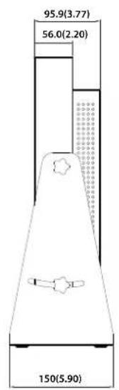
- Unit: mm(inches)
LVM-246A-N1 : SIDE / BIRD'S EYE VIEW
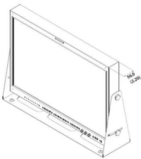
natural_image
Technical line drawing of a rectangular electronic device with internal components and mounting base (no text or symbols)
* The difference between LVM-246A and LVM-246A-N1 is the depth only. Other specifications and functions are exactly the same between the two models.
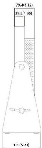
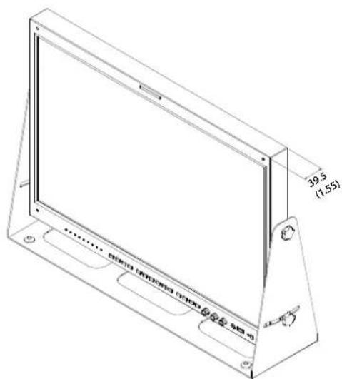
natural_image
Technical line drawing of a rectangular electronic device with internal components and mounting base (no text or symbols)
03 CONTROLS & FUNCTIONS
- Used to display the current input mode.
- Input Mode
VIDEO: Composite
S-VID: S-Video
COMP: Component
RGB: RGB
DVI-A : DVI ANALOG
DVI-D : DVI DIGITAL
HDMI: HDMI
SDI-A : SDI-A
SDI-B : SDI-B
- Used to select desired Analog input.
- Press the button to activate the analog input menu-selection, then use UP and DOWN button to select desired input.
* Please refer to "7. Button Functions [1] ANALOG Button" for more information.
- Used to select desired Digital input. (HDMI, DVI Digital)
- Press the Digital Button to activate the Digital input menu-selection, then use the Knob to select desired input.
* Please refer to "7. Button Functions [2] DIGITAL" for more information.
- Used to select SDI-A input.
- Used to select SDI-B input.
- Performs the function that the user set as hot-keys.
- The selectable hot-key menu comes up when you hold the keys for 2 seconds.
You can select the hot-key functions from it.
- Used to change the scan mode. Press the button to activate through the scan modes: Zero Scan > 2:1 Scan > 1:1 Scan > Fit Width > Over Scan > User Aspect
- Supported modes vary depending on the input video resolution.
* Please refer to "8. Other Functions [1]SCAN" for more information.
- Used to activate/deactivate the Marker.
- The Marker is normally displayed when you select Aspect ratio you want in OSD Menu.
- Activates OSD menu.
- Used to move the cursor down while OSD menu is activated and to decrease the value of the selected feature.
- Used to move the cursor up while OSD menu is activated and to increased the value of the selected feature.
- Used to confirm a chosen value.
- Volume window is activated when OSD menu is not activated. You can adjust the volume value with UP/DOWN keys.
- Used to move the picture position in order in 1:1 SCAN mode, when a original image is bigger than resolution.
03 CONTROLS & FUNCTIONS
- Used to adjust the picture sharpness. The value is selectable between 0\~24.
- It is not available in DVI ANALOG.
• [BRIGHT] Knob
- Used to adjust the degree of brightness. The value is selectable between -100\~100.
• [CONTRAST] Knob
- Used to adjust the contrast.
The value is selectable between -100\~100.
• [AUDIO OUT] (Phone jack)
- Outputs the dis-embedded audio signal: the HDMI audio signal or the SDI audio channel which is selected in [Audio] menu.
• [USB]
- Updates new firmware and color calibration.
• [POWER INDICATOR] Lamp
- Indicates the status of power connection and monitor operation.
- The LED is off with power off.
- The LED is red when the monitor is in waiting mode with power on.
- The LED is green when the monitor is operating.
- Turns on or off the monitor power.
• [TALLY] Lamp
- Tally lamp that can be toggled in green or red using the REMOTE(RJ-45) port.
03 CONTROLS & FUNCTIONS
LVM-246A(-N1): REAR
• [REMOTE] (RJ-45)
- Provides connection to control equipment for external monitor control.
- Features can be changed in the [GPI / UMD] section of OSD menu.
• [RS422 IN/OUT] (RJ-45)
- Controls the monitor by a protocol provided by TVLogic or supports TSL protocol.
• [DVI-I] (DVI-I)
- Signal input terminal for DVI ANALOG or DVI DIGITAL signal.
• [HDMI(HDCP)] (HDMI)
- Signal input terminal for HDMI signal.
• [CVBS1/Y/G/S-Y] (BNC)
- Signal input terminal for COMPOSITE 1, S-VIDEO Y, COMPONENT Y, RGB G signal.
• [CVSBS2/Pb/B] (BNC)
- Signal input terminal for COMPOSITE 2, RGB B, COMPONENT Pb signal.
• [CVSBS3/Pr/R/S-C] (BNC)
- Signal input terminal for COMPOSITE 3, S-VIDEO C, COMPONENT Pr, RGB R signal.
• [SDI-IN A] (BNC)
- Signal input terminal for 3G/HD/SD SDI signal.
• [SDI-IN B] (BNC)
- Signal input terminal for 3G/HD/SD SDI signal.
• [SDI-OUT] (BNC)
- Signal output terminal for 3G/HD/SD SDI input signal through SDI-IN.
* SDI Output is not activated when the unit is turned off or in Standby mode.
• [AUDIO-IN] (Phone Jack)
- Inputs the analog audio out of the external equipment.
- The analog input audio can be selected in [Audio] - [Em. Audio Left/Right] menu.
• AC IN
- 100 \~ 240V (50/60Hz)
• DC IN
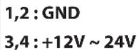
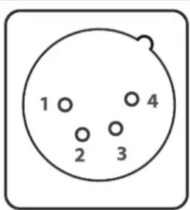
- 12V - 24V (MAX 3.5A - 2A)
DC IN socket