
t505 - Thin client HP - Free user manual and instructions
Find the device manual for free t505 HP in PDF.


| Product Type | Thin Client |
| Brand | HP |
| Model | t505 |
| Dimensions (W x D x H) | 200 mm x 150 mm x 30 mm |
| Weight | 0.8 kg |
| Power Supply | External AC adapter, 12V DC, 2A |
| CPU | VIA Eden 1.0 GHz |
| RAM | 1 GB DDR2 (non-upgradeable) |
| Storage | 512 MB flash memory |
| Operating System | Windows XP Embedded SP2 |
| Networking | 10/100 Ethernet RJ-45 |
| Video Output | VGA, max resolution 1600x1200 |
| Audio | Line-out jack |
| USB Ports | 4 x USB 2.0 |
| Security | Kensington lock slot, TPM 1.2 |
| Maintenance | No user-serviceable parts; external peripherals only |
| Spare Parts | AC adapter, power cord |
| General | Fanless design, low power consumption (~15W) |
Frequently Asked Questions - t505 HP
User questions about t505 HP
0 question about this device. Answer the ones you know or ask your own.
Ask a new question about this device
Download the instructions for your Thin client in PDF format for free! Find your manual t505 - HP and take your electronic device back in hand. On this page are published all the documents necessary for the use of your device. t505 by HP.
USER MANUAL t505 HP
Troubleshooting Guide
HP t505 Flexible Thin Client
© Copyright 2013 Hewlett-Packard Development Company, L.P. The information contained herein is subject to change without notice.
Microsoft and Windows are trademarks of Microsoft Corporation in the U.S. and other countries.
The only warranties for HP products and services are set forth in the express warranty statements accompanying such products and services. Nothing herein should be construed as constituting an additional warranty. HP shall not be liable for technical or editorial errors or omissions contained herein.
This document contains proprietary information that is protected by copyright. No part of this document may be photocopied, reproduced, or translated to another language without the prior written consent of Hewlett-Packard Company.
Troubleshooting Guide
Thin Client
First Edition (April 2013)
Document Part Number: 719622-001
About This Book
WARNING! Text set off in this manner indicates that failure to follow directions could result in bodily harm or loss of life. CAUTION: Text set off in this manner indicates that failure to follow directions could result in damage to equipment or loss of information. NOTE: Text set off in this manner provides important supplemental information.
Table of contents
1 Product Description .... 1
Product features ...... 1
Serial Number Location 2
Front Panel Components 3
Rear Panel Components 4
Installing the Rubber Feet 4
Installing the Stand 5
Removing the Stand 6
2 Hardware Changes 7
General Hardware Installation Sequence 7
Removing and Replacing the Side Access Panel 8
Removing the Side Access Panel 8
Replacing the Side Access Panel 9
Installing Thin Client Options 10
Removing and Replacing the Battery 10
External Drives 11
Configuring Powered Serial Ports 12
3 BIOS Settings, (F10) Utility 21
Using the BIOS Settings 21
Changing BIOS Settings from the reset utility 21
Changing BIOS Settings Using the F10 Utility 22
Setup Utility—System Information 23
Setup Utility—Standard CMOS Features 23
Setup Utility—Advanced BIOS Features 23
Setup Utility—Integrated Peripherals 24
Setup Utility—Power Management Setup 25
Setup Utility—Utility Task Actions 25
4 Diagnostics and Troubleshooting 26
LEDs 26
Power-On Sequence 27
Power-On Diagnostic Tests 27
Beep Codes 28
POST Error Messages 28
Troubleshooting 29
Basic Troubleshooting 29
Diskless (No-Flash) Unit Troubleshooting 30
Troubleshooting Flowcharts 32
Initial Troubleshooting 32
Initial Troubleshooting Part 2 .... 33
No Power, Part 1 .... 34
No Power, Part 2 .... 35
No Power, Part 3 .... 36
No Video, Part 1 .... 37
No Video, Part 2 .... 38
No Video, Part 3 39
No Video, Part 4 .... 40
Error Messages 41
No OS Loading 42
OS Not Loading from Flash 43
Non-Functioning Pointing Device or Keyboard 44
No Internal Network Connection 45
No Audio 46
No IP Address 47
Booting in Continuous Loop 48
5 Restoring the Flash Image 49
System Requirements 49
Getting Started 49
Creating an ISO Image 50
Formatting a USB Flash Drive 50
Unpacking the Image and Tools for Deployment 51
Deploying with PXE 51
Appendix A Adding an Image Restore Tool 52
Appendix B Configuring a PXE Server 53
Prerequisites 53
Installing Remote Installation Services (RIS PXE Server) 53
Authorizing Remote Installation Services (RIS PXE Server) 53
Configuring Remote Installation Services 54
Set User Permissions on the Active Directory Server 54
RIS Menu 55
Creating Network Bootable Disk to Map Drives 55
For More Information 55
Appendix C FTP Update 56
Server Requirements 56
DCHP Server 56
FTP Server 56
Description 57
Host Settings 57
Select Image to Update 58
Appendix D System BIOS 60
Restoring or updating a BIOS 60
Appendix E Electrostatic Discharge 61
Preventing Electrostatic Damage 61
Grounding Methods 61
Appendix F Specifications 62
Index 64
1 Product Description
The following features are common to all HP thin clients:
• No hard drives or diskette drives • 5-minute hardware setup time • Central deployment and management using HP Management Solutions
The following features are specific to the t505 thin client:
Intel Atom D525 single core processor • Intel PCH NM10 chipset • Integrated graphics, selectable at 64/128/256MB • DDR3 SODIMM, 1 socket, up to 2 GB

NOTE: 1Rx16 and 2Rx8 SODIMMS not supported
• Front I/O: 2 USB, 1 mic, 1 headphone • Rear I/O: 2 USB, 2 PS2, 1 NIC 10/100, 1 parallel, 1 VGA, 4 serial ports • VESA mount, supports both horizontal and vertical orientations • Kensington lock slot
Operating systems
The t505 thin client models support the following operating systems:
• Windows Embedded Standard (WES) 2009 • Windows Embedded Standard (WES) 7 (e32) HP ThinPro
Product features
For more information, refer to the model-specific QuickSpecs at http://h18004.www1.hp.com/products/quickspecs/QuickSpecs_Archives/QuickSpecs_Archives.html.
Serial Number Location
Every thin client includes a unique serial number located as shown in the following illustration. Have this number available when contacting HP customer service for assistance.
Figure 1-1 Serial number location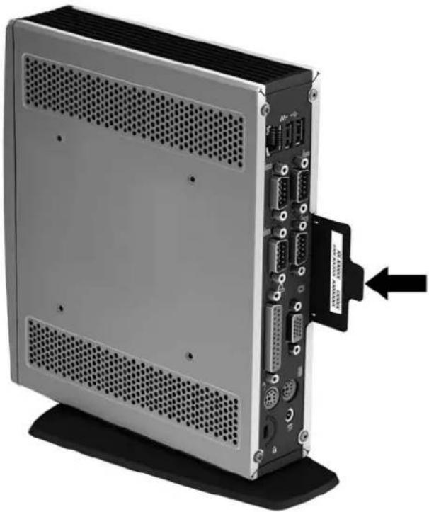
Front Panel Components
For more information, go to http://www.hp.com and search for your specific thin client model to find the model-specific QuickSpecs.
Figure 1-2 Front panel components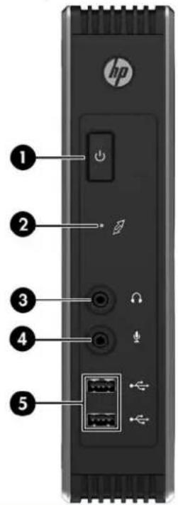
(1) Power button (4) Line-in (microphone) connector (2) Flash activity LED (5) Universal serial bus (USB) connectors (2) (3) Line-out (headphone) audio connector
Rear Panel Components
For more information, go to http://www.hp.com and search for your specific thin client model to find the model-specific QuickSpecs.
Figure 1-3 Rear panel components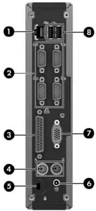
(1) Ethernet RJ-45 connector (5) Cable lock slot (2) Serial connectors (4) (6) Power connector (3) Parallel connector (7) VGA connector (4) PS/2 connectors (2) (8) Universal serial bus (USB) connectors (2)
Installing the Rubber Feet
You may want to use your thin client in a horizontal orientation. You can install rubber feet on the left side of the unit to help keep the unit safely in place.
To install the rubber feet:
- Locate the VESA (Video Electronics Standards Association) holes in the left side of the thin client.
CAUTION: If you use the thin client in a horizontal orientation without the rubber feet, it may slide and result in equipment damage.
- Remove the feet from their backing.
- Align the feet with their holes and press them in securely.
Figure 1-4 Installing the rubber feet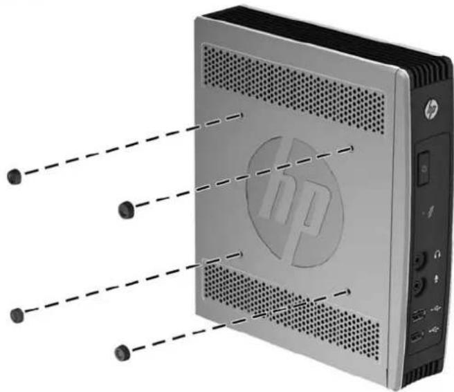
Installing the Stand
If you wish to use the thin client in a vertical orientation, you should install the stand for stability.
- Turn unit upside down.
- Locate the slots on the bottom of the unit into which the tabs on the stand fit. Position the stand with the wide part toward the front of the unit. Align the tabs on the widest part of the stand with the slots approximately 7.6 cm (3 inches) from the front of the unit and the tabs on the narrower part with the slots approximately 3.8 cm (1.5 inches) from the rear of the unit.
- Insert the tabs into the slots and slide the stand forward until it locks into place.
Figure 1-5 Installing the stand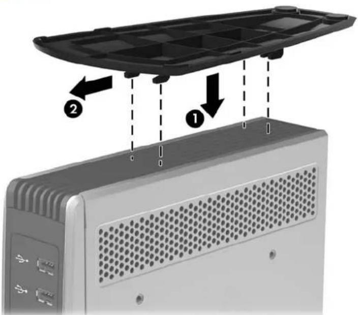
Removing the Stand
- Turn unit upside down.
- Press the tab (1), then slide the stand toward the rear of the thin client and lift it off the unit (2).
Figure 1-6 Removing the stand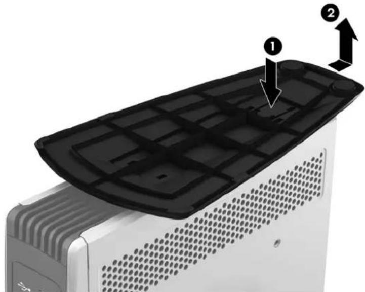
2 Hardware Changes
General Hardware Installation Sequence
To ensure the proper installation of thin client hardware components:
- Back up any data, if necessary.
- If the thin client is powered on:
a. Turn off the computer properly through the operating system, then turn off any external devices. b. Disconnect the power cord from the power outlet and disconnect any external devices. c. Disconnect any external devices or cables, such as a cable lock.
WARNING! To reduce the risk of personal injury from electrical shock and/or hot surfaces, be sure to disconnect the power cord from the wall outlet and allow the internal system components to cool before touching. WARNING! To reduce the risk of electrical shock, fire, or damage to the equipment, do not plug telecommunications or telephone connectors into the network interface controller (NIC) receptacles. CAUTION: Static electricity can damage the electronic components of the thin client or optional equipment. Before beginning these procedures, ensure that you are discharged of static electricity by briefly touching a grounded metal object. See Electrostatic Discharge on page 61 for more information.
- Remove the side access panel. See Removing and Replacing the Side Access Panel on page 8 for more information.
- Remove any hardware that you will replace.
- Install or replace equipment. For removal and replacement procedures, see Removing and Replacing the Battery on page 10.
NOTE: Option kits include more detailed installation instructions.
- Replace the side access panel. See Removing and Replacing the Side Access Panel on page 8.
- Reconnect any external devices and power cords.
- Turn on the monitor, the thin client, and any devices you want to test.
- Load any necessary drivers.

NOTE: You can download select hardware drivers from HP. Go to http://www.hp.com and search for your specific thin client model.
- Reconfigure the thin client, if necessary.
Removing and Replacing the Side Access Panel
Removing the Side Access Panel

WARNING! Before removing the side access panel, ensure that the thin client is turned off and the power cord is disconnected from the electrical outlet.
To remove the access panel:
- Lay the unit flat on a stable surface with the right side up and the left side down.
- Remove the two screws that secure the access panel to the chassis (1).
- Slide the access panel about 8.3 mm (1/3 inch) toward the rear of the unit (2), and then lift the access panel up and off the unit (3).
Figure 2-1 Removing the side access panel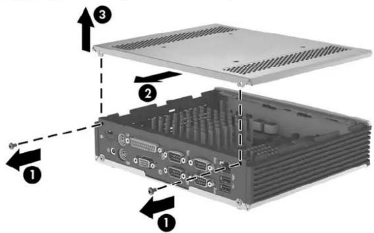
Replacing the Side Access Panel
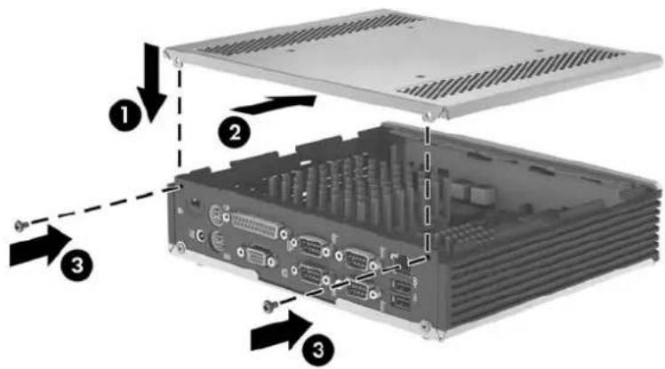
To replace the access panel:
- Align the tabs on the access panel with the slots in the both sides of the chassis and place the access panel on the side of the unit, offset about 8.3 mm (1/3 inch) toward the top of the unit (1).
- Slide the panel toward the front of the unit until the panel is flush with the bottom panel of the chassis (2).
- Insert and fasten the two screws to secure the side access panel to the chassis.
Installing Thin Client Options
Various options can be installed on the thin client:
• Removing and Replacing the Battery on page 10 • External Drives on page 11
Removing and Replacing the Battery
Before beginning the replacement process, review General Hardware Installation Sequence on page 7 for procedures you should follow before and after installing or replacing hardware.

WARNING! Before removing the side access panel, ensure that the thin client is turned off and the power cord is disconnected from the electrical outlet.
To remove and replace the battery:
- Locate the battery on the system board.
- To release the battery from its holder, squeeze the metal clamp that extends above one edge of the battery. When the battery pops up, lift it out (1).
Figure 2-2 Removing and replacing the internal battery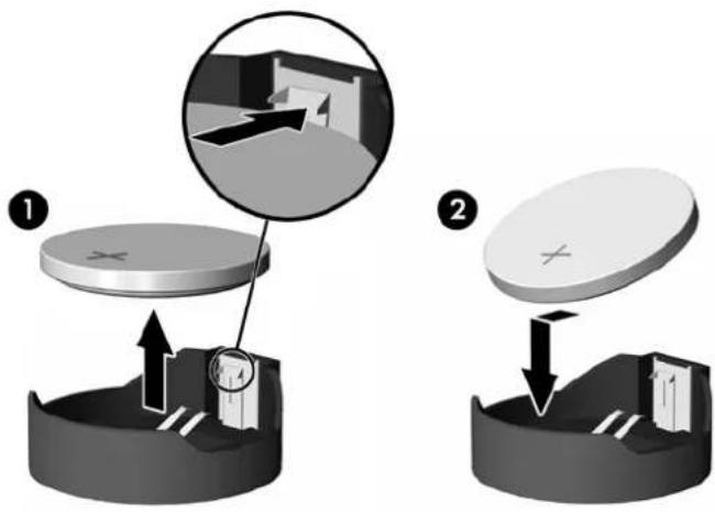
- To insert the new battery, slide one edge of the replacement battery under the holder's lip with the positive side up (2). Push the other edge down until the clamp snaps over the other edge of the battery.
HP encourages customers to recycle used electronic hardware, HP original print cartridges, and rechargeable batteries. For more information about recycling programs, go to http://www.hp.com/go/recycle.

Batteries, battery packs, and accumulators should not be disposed of together with the general household waste. In order to forward them to recycling or proper disposal, please use the public collection system or return them to HP, an authorized HP partner, or their agents.

Please recycle waste batteries.
The Taiwan EPA requires dry battery manufacturing or importing firms, in accordance with Article 15 or the Waste Disposal Act, to indicate the recovery marks on the batteries used in sales, giveaways, or promotions. Contact a qualified Taiwanese recycler for proper battery disposal.
External Drives
Various external USB drives are available as options for these thin clients. For more information about these drives, visit http://www.hp.com and search for your specific thin client model, or refer to the instructions that accompany the option.
For more information about available options, visit the HP website http://www.hp.com and search for your specific thin client model.
Configuring Powered Serial Ports
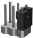
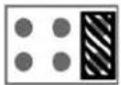
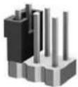
Three configurable, powered serial ports, COM 2, COM 3, and COM 4, are standard on the thin client. COM 1 is a standard, non-powered serial port that cannot be configured. Some devices use a powered serial port. If the serial port is configured as a powered port, devices that support a powered serial interface do not require an external power source.
Figure 2-3 Powered Serial Ports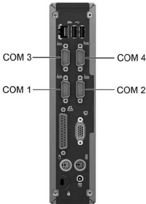
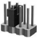
The serial port jumpers on the system board are located as shown in the following illustration:
Figure 2-4 Serial Port Jumper Locations on the System Board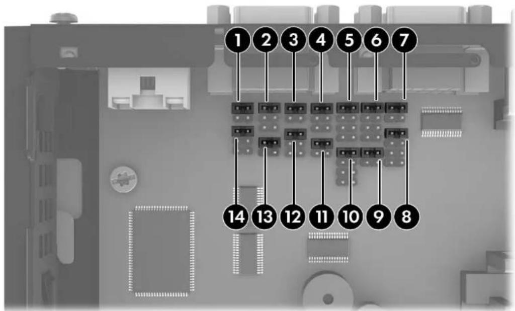
| Item Jumper | |||
| 1 | C | O | M |
| 2 | C | O | M |
| 3 | C | O | M |
| 4 | C | O | M |
| 5 | C | O | M |
| 6 | C | O | M |
| 7 | C | O | M |
| 8 | C | O | M |
| 9 | C | O | M |
| 10 COM2 SP29 | |||
| 11 COM4 SP42 | |||
| 12 COM4 SP44 | |||
| 13 COM3 SP32 | |||
| 14 COM3 SP34 | |||
| 3 | S | P | 3 | 3 |
| 3 | S | P | 3 | 1 |
| 4 | S | P | 4 | 3 |
| 4 | S | P | 4 | 1 |
| 2 | S | P | 2 | 8 |
| 2 | S | P | 2 | 3 |
| 2 | S | P | 2 | 1 |
| 2 | S | P | 2 | 2 |
| 2 | S | P | 2 | 4 |
Before beginning the configuration process, review General Hardware Installation Sequence on page 7 for procedures you should follow before and after installing or replacing hardware.

WARNING! Before removing the side access panel, ensure that the thin client is turned off and the power cord is disconnected from the electrical outlet.
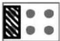
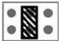
To configure the serial ports:
- Locate the serial port and jumper.
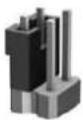
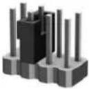
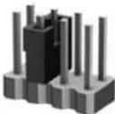
- Place jumpers on the appropriate pins. (See Table 2-3 Configuring Serial Port Power on page 15 to determine the appropriate pins.)
CAUTION: An unsupported configuration can cause severe equipment damage. Carefully verify COM Port Jumper locations and supported configurations before you configure a serial port. See Figure 2-4 Serial Port Jumper Locations on the System Board on page 13 and Table 2-3 Configuring Serial Port Power on page 15 for Jumper locations and supported configurations.
Table 2-1 COM Port Default Configuration
| pin # COM1 COM2 COM3 COM4 |
| pin 1 DCD +5V +5V +5V |
| pin 2 RXD RXD RXD RXD |
| pin 3 TXD TXD TXD TXD |
| pin 4 DTR DTR DTR DTR |
| pin 5 GND GND GND GND |
| pin 6 DSR DSR DSR DSR |
| pin 7 RTS RTS RTS RTS |
| pin 8 CTS RXD (TTL) CTS CTS |
| pin 9 RI TXD (TTL) RI RI |
Table 2-2 COM Port Functionality
| pin # COM1(Standard) | COM2-Cable Connection(Customized) | COM3(Customized) | COM4(Customized) | |
| pin 1 DCD +5V/DCD +5V/+12V/DCD | +5V/+12V/DCD | |||
| pin 2 RXD RXD/TXD/RXD (TTL)/ | TXD (TTL) | RXD/TXD | RXD/TXD | |
| pin 3 TXD TXD/RXD/TXD (TTL)/ | RXD (TTL) | TXD/RXD | TXD/RXD | |
| pin 4 DTR DTR/+5V | DTR/+5V/+12V | DTR/+5V/+12V | ||
| pin 5 GND GND GND GND | ||||
| pin 6 DSR DSR DSR DSR | ||||
| pin 7 RTS RTS RTS RTS | ||||
| pin 8 CTS RXD/TXD/RXD (TTL)/ | TXD (TTL) | CTS CTS | ||
| pin 9 RI TXD/RXD/TXD (TTL)/ | RXD (TTL) | RI RI | ||

CAUTION: To prevent severe equipment damage, carefully verify the location of the COM Port Jumper before you configure it. See Figure 2-4 Serial Port Jumper Locations on the System Board on page 13 for locations.

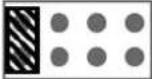
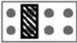
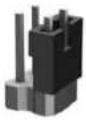
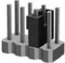
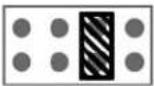
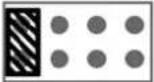
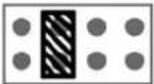
NOTE: The jumpers in the following table are in the same orientation illustrated in Figure 2-4 Serial Port Jumper Locations on the System Board on page 13.
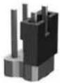
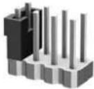
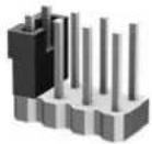
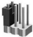
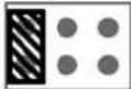
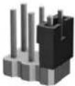
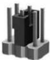
Table 2-3 Configuring Serial Port Power
| COM 2 - SP21 | |||
 |  | Pin1:+5V (Default) | 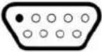 |
 |  | Pin1:DCD | 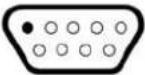 |
| COM 2 - SP22 | |||
 |  | Pin2:RXD (Default) | 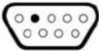 |
 |  | Pin2:TXD | 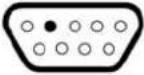 |
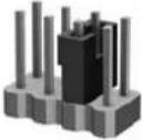 | 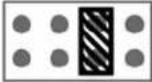 | Pin2:RXD_TTL | 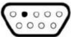 |
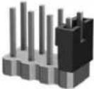 | 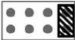 | Pin2:TXD_TTL | 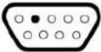 |
| COM 2 - SP23 | |||
 | 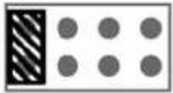 | Pin3:TXD (Default) | 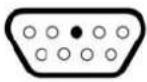 |
 | 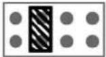 | Pin3:RXD | 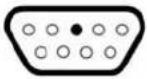 |
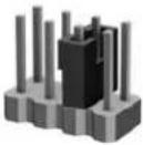 | 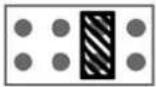 | Pin3:TXD_TTL | 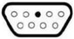 |
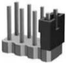 | 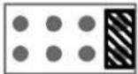 | Pin3:RXD_TTL | 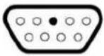 |
| COM 2 - SP24 | |||
| ZW67 |  | Pin4:DTR (Default) | 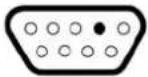 |
 |  | Pin4:+5V | 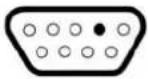 |
| COM2-SP28 | |||
 |  | Pin8:RXD | 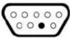 |
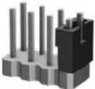 | 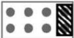 | Pin8:TXD | 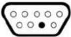 |
 |  | Pin8:RXD_TTL(Default) | 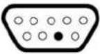 |
 |  | Pin8:TXD_TTL | 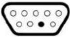 |
| COM2-SP29 | |||
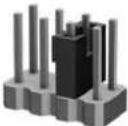 | 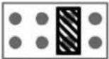 | Pin9:TXD | 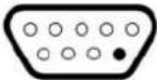 |
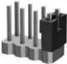 | 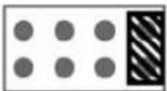 | Pin9:RXD | 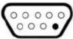 |
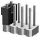 | 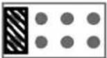 | Pin9:TXD_TTL(Default) | 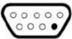 |
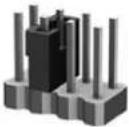 | 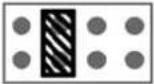 | Pin9:RXD_TTL | 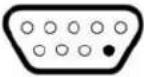 |
| COM 3 - SP31 | |||
 |  | Pin1:+5V(Default) | 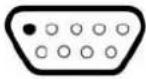 |
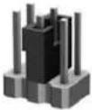 | 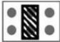 | Pin1:+12V | 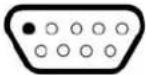 |
 | 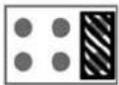 | Pin1:DCD | 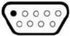 |
| COM 3 - SP32 | |||
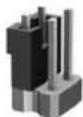 |  | Pin2:RXD(Default) | 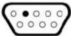 |
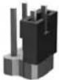 |  | Pin2:TXD | 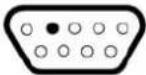 |
| COM 3 - SP33 | |||
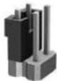 |  | Pin3:TXD(Default) | 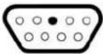 |
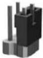 |  | Pin3:RXD | 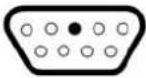 |
| COM 3 - SP34 | |||
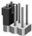 | 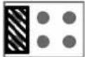 | Pin4:DTR(Default) | 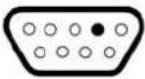 |
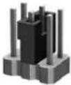 | 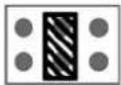 | Pin4:+5V | 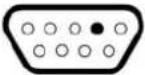 |
 |  | Pin4:+12V | 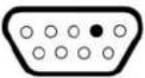 |
| COM 4 - SP41 | |||
 |  | Pin1:+5V(Default) |  |
 |  | Pin1:+12V | 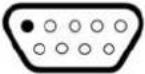 |
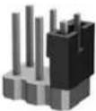 | 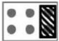 | Pin1:DCD | 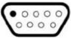 |
| COM 4 - SP42 | |||
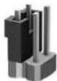 |  | Pin2:RXD(Default) | 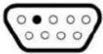 |
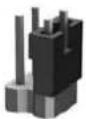 |  | Pin2: TXD | 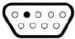 |
| COM 4 - SP43 | |||
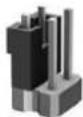 |  | Pin3:TXD (Default) | 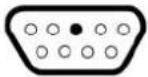 |
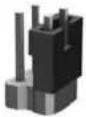 |  | Pin3: RXD | 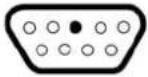 |
| COM 4 - SP44 | |||
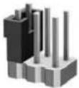 | 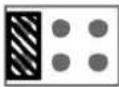 | Pin4:DTR(Default) | 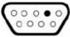 |
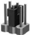 | 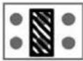 | Pin4:+5V | 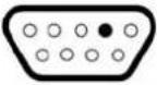 |
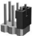 | 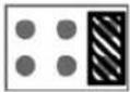 | Pin4:+12V | 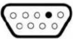 |
3 BIOS Settings, (F10) Utility
Using the BIOS Settings
Changing BIOS Settings from the reset utility
Some BIOS settings may be changed locally within the operating system without having to go through the F10 utility. This table identifies the items that can be controlled with this method.
| BIOS Setting Default Value Other Values | ||
| 1st Boot Device USB ATA Flash, Network, Disabled | ||
| 2nd Boot Device ATA Flash USB, Network, Disabled | ||
| 3rd Boot Device Network ATA Flash, USB, Disabled | ||
| Boot Up NumLock Off On | ||
| F12 Boot Enabled Disabled | ||
| Integrated Audio Enabled Disabled | ||
| Network Controller Enabled Disabled | ||
| Serial Port 1 3F8/IRQ4, other values = 2F8/IRQ3, 3E8/IRQ4, 2E8/IRQ3 | Disabled | |
| Serial Port 2 2F8/IRQ3, other values = 3F8/IRQ4, 3E8/IRQ4, 2E8/IRQ3 | Disabled | |
| Serial Port 3 3E8/IRQ5, other values = 3F8/IRQ5, 2F8/IRQ10, 2E8/IRQ10 | Disabled | |
| Serial Port 4 2E8/IRQ10, other values = 3F8/IRQ5, 2F8/IRQ10, 3E8/IRQ5 | Disabled | |
| Parallel Port | 378/IRQ7, other values = 278/IRQ5, 3BC/IRQ7 | Disabled |
| PWRON After PWR-Fail | Former State | On, Off |
| Wake-on-PME | Enabled Disabled | |
| BIOS Wake Up | Disabled | Enabled, days of the week & time |
| Asset Tag No | 00000000000000000 | User input (18 chars) |
| Setup Password | blank | User input (8 chars max) |
| Power-On Password | blank | User input (8 chars max) |
| Parallel Mode ECP/EPP | Standard, EPP, ECP | |
| ECP Mode Use DMA DMA3 DMA1 |
| USB Controller Enabled Disabled |
| External USB Ports Enabled Disabled |
| Halt On All, but Keyboard No Errors |
| Security Option Setup Always |
| USB Keyboard Support Enabled Disabled |
| USB Mouse Support Disabled Enabled |

NOTE: Settings that can be controlled from the operating system with reset can also be controlled remotely by sending the client an Altiris job that uses the reset tool to apply the setting changes.
Changing BIOS Settings Using the F10 Utility
- Turn on or restart the thin client.
- As soon as the thin client is turned on, press F10 when the "press F10" prompt appears on the screen to enter the Setup Utility.

NOTE: If you do not press F10 at the appropriate time, you must restart the thin client and again press F10 when the F10=Setup message displays in the task bar at the bottom of the screen. When the F10 POST Screen display is set to zero seconds, it may be necessary to press and hold F10 on the keyboard, then power on the thin client.
- The Setup Utility screen is divided into five menu headings and five task actions.
The Menu Headings are: System Information, Standard CMOS Features, Advanced BIOS Features, Integrated Peripherals, Power Management Setup
The Task Actions are: Load Factory Defaults, Set Administrative Password, Set User Password, Save & Exit Setup, Exit without Saving
Use the arrow keys (up and down or left and right) to select the appropriate heading, and then press Enter. To return to the Setup Utility menu, press the Esc key.
- To apply and save changes, select Save & Exit Setup.
If you have made changes that you do not want applied, select Exit without Saving.
To reset to original factory settings, select Load Factory Defaults.

CAUTION: Do NOT turn the thin client power off while the ROM is saving the Setup (F10) changes, because the CMOS could become corrupted. It is safe to turn off the computer only after exiting the F10 Setup screen.
Table 3-1 Setup (F10) Utility Main Menu
| Heading | Table |
| System Information | Setup Utility—System Information on page 23 |
| Standard CMOS Features | Setup Utility—Standard CMOS Features on page 23 |
| Advanced BIOS Features | Setup Utility—Advanced BIOS Features on page 23 |
| Integrated Peripherals | Setup Utility—Integrated Peripherals on page 24 |
| Power Management Setup | Setup Utility—Power Management Setup on page 25 |
Setup Utility—System Information

NOTE: Support for specific Setup options may vary depending on the hardware configuration.
Table 3-2 Setup Utility—System Information
| Option Description |
| Product Name (view only) |
| Processor Type (view only) |
| Processor Speed (view only) |
| Memory size (view only) |
| System ROM (view only) |
| Integrated MAC (view only) |
| UUID (view only) |
| Chassis Serial # (view only) |
| Asset Tracking Number (view only) |
| Asset Tag Enter asset tracking number. |
Setup Utility—Standard CMOS Features
Table 3-3 Setup Utility—Standard CMOS Features
| Option Description | |
| Date (mm:dd:yy) | Allows you to set system date |
| Time (hh:mm:ss) | Allows you to set system time. |
| Primary IDE Master | Indicates ATA Flash settings. |
| Secondary IDE Master | Indicates ATA Flash settings. |
| Halt On | Allows you to select system response of All Errors, No Errors, or All But Keyboard when POST Error has been detected. Default is All But Keyboard. |
Setup Utility—Advanced BIOS Features
Table 3-4 Setup Utility—Advanced BIOS Features
| Option | Description |
| Quick Power-on Self Test | Allows the system to skip certain tests while booting. This will decrease the time needed to boot the system. Enabled/Disabled. Default is Enabled |
| 1st Boot Device Select Boot Device Priority. Default is USB. | |
| 2nd Boot Device Select Boot Device Priority. Default is ATA Flash. | |
| 3rd Boot Device Select Boot Device Priority. Default is Network. | |
| Boot Up Numlock Status | Select power on state for Numlock. Default is OFF. |
| POST Delay (secs) | Set a delay that is added to POST to allow more time to press F10 to enter the Setup Utility. Default is None. |
| F12 Boot Enable/Disable F12 network boot. Default is Enabled. | |
Setup Utility—Integrated Peripherals
Table 3-5 Setup Utility—Integrated Peripherals
| Option Description | |
| Integrated Audio | Enable or Disable Onboard AC97 Audio controller. Default is Enabled. |
| Network Controller | Enable or Disable Onboard LAN device. Default is enabled. |
| USB Controller Enable or Disable USB controller. Default is enabled. | |
| Advanced USB Options | Enable or Disable USB external ports. Default is enabled. |
| USB Keyboard Support | Allows use of USB keyboard under DOS. Default is enabled. |
| USB Mouse Support | Allows use of USB Mouse under DOS. Default is disabled. |
| Serial Port 1 Select serial port base IO port address and IRQ. Default is 3F8/IRQ4 | |
| Serial Port 2 Select serial port base IO port address and IRQ. Default is 2F8/IRQ3 | |
| Serial Port 3 Select serial port base IO port address and IRQ. Default is 3E8/IRQ5 | |
| Serial Port 4 Select serial port base IO port address and IRQ. Default is 2E8/IRQ10 | |
| Parallel Port Select parallel port base IO port address and IRQ. Default is 378/IRQ7. | |
| Parallel Mode | Select parallel port transfer mode of Standard, EPP, ECP, or ECP/EPP. Default is ECP/EPP. |
| ECP Mode Use DMA | Select DMA channel of 1 or 3 if parallel is operated in ECP mode. Default is 3. |
Setup Utility—Power Management Setup
Table 3-6 Setup Utility—Power Management Setup
| Option Description | |
| PWRON After PWR-Fail | When power is lost and comes back, the option determines what power state the system should go to. Options are Off, On, and Former-Sts. Default is Former-Sts. |
| Wake on PME | Enable/disable system wake-up capability for events received through the PCI bus. Default is enabled. |
| BIOS Wake up Enable RTC alarm wake-up. Default is disabled. | |
| Day of Week Select the alarm RTC wake-up day of Sunday through Saturday. | |
| Time of Day Select the alarm RTC wake-up time of day (hh:mm). | |
Setup Utility—Utility Task Actions
Table 3-7 Setup (F10) Utility Task Actions
| Heading Table | |
| Load Factory Defaults | Select Yes or No (Y/N) |
| Set Administrator Password | Allows you to set, change, and disable the administrator password. |
| Set User Password | Allows you to set, change, and disable the user password.NOTE:When the user password is set, it prevents unauthorized access to the user's setup. User password provides read-only access to Setup options. |
| Save & Exit Setup Saves data to CMOS, then exit the Setup Utility. | |
| Exit without Saving Exit the Setup Utility without saving any changes. | |
4 Diagnostics and Troubleshooting
LEDs
Table 4-1 Power and IDE Flash Activity LEDs
| LED Status | |
| Power LED Off When the unit is plugged into the wall socket and the Power LED is off, the unit is powered off.However, the network can trigger a Wake On LAN event in order to perform management functions. | |
| Power LED On | Displays during boot sequence and while the unit is on. During boot sequence, hardware initialization is processed and startup tests are performed on the following:Processor initializationMemory detection and initializationVideo detection and initializationNOTE: If one of the tests fails, the unit will simply stop, but the LED will stay on. If the video test fails, the unit beeps. There are no messages sent to video for any of these failed tests.NOTE: After the video is initialized, anything that fails will have an error message. |
| NOTE: RJ-45 LEDs are located inside the RJ-45 connector on the top, rear panel of the thin client. The LEDs are visible when the connector is installed. Blinking green indicates network activity, and amber indicates a 100MB speed connection. | |
| IDE LED is Off | When the unit is powered on and the flash activity light is off, then there is no access to the system flash. |
| IDE LED blinks Green Indicates the system is accessing the internal IDE flash. | |
Power-On Sequence
At power-on, the flash boot block code initializes the hardware to a known state, then performs basic power-on diagnostic tests to determine the integrity of the hardware. Initialization performs the following functions:
- Initializes CPU and memory controller.
- Initializes VGA software.
- Initializes and configures all PCI devices.
- Initializes the video to a known state.
- Initializes USB devices to a known state.
- Performs power-on diagnostics. For more information, see Power-On Diagnostic Tests on page 27.
- The unit boots the operating system.
Power-On Diagnostic Tests
The power-on diagnostics performs basic integrity tests of the hardware to determine its functionality and configuration. If a diagnostic test fails during hardware initialization, the unit simply stops. There are no messages sent to video.

NOTE: You may try to restart the unit and run through the diagnostic tests a second time to confirm the first shutdown.
The following table lists the tests that are performed on t5000 units.
Table 4-2 Power-On Diagnostic Test
| Test Description | |
| Boot Block Checksum Tests boot block code for proper checksum value | |
| DRAM Simple write/read pattern test of the first 640k of memory | |
| Parallel Port Initiates the port's driver and determines if the device is present | |
| Serial Port | Tests the serial port using simple port verification test to determine if ports are present |
| Timer Tests timer interrupt by using polling method | |
| RTC CMOS battery Tests integrity of RTC CMOS battery | |
| NAND flash device Tests for proper NAND flash device ID present | |
Beep Codes
If there are no video errors, the system goes directly to POST messages.
| Beep Code Description | |
| 1 long, 2 short | A video error has occurred and the BIOS cannot initialize the video screen to display any additional information. |
| 1 long, 3 short System running in boot block recovery mode. | |
| 2 long, 2 short No memory detected. | |
| 2 long, 3 short Unsupported SODIMM installed. | |
POST Error Messages
Table 4-3 POST Error Messages
| POST Error Message Description | |
| BIOS ROM checksum error - System halted | The checksum of the BIOS code in the BIOS chip is incorrect, indicating the BIOS code may have become corrupt. To restore a corrupt BIOS, refer toSystem BIOS on page 60or call your local HP Call Center for a diagnosis. For phone numbers of an HP Call Center near you, visit the following Web site:http://www.hp.com/cgi-bin/hpsupport/index.pl |
| CMOS battery failed | The CMOS battery is no longer functional. For information on replacing the battery, refer toRemoving and Replacing the Battery on page 10. |
| CMOS checksum error - Defaults loaded | Checksum of CMOS is incorrect, so the system loads the default equipment configuration. A checksum error may indicate that CMOS has become corrupt. A weak battery may have caused this error. Replace the battery if necessary. For more information, refer toRemoving and Replacing the Battery on page 10. |
| CPU at nnnn Displays the running speed of the CPU. | |
| Press ESC to skip memory test | The user may pressEscto skip the full memory test. |
| Hard Disk Install Failure Cannot find or initialize the hard drive controller or the drive. Make sure the controller is installed correctly. If no hard drives are installed, be sure the Hard Drive selection in Setup is set toNONE. | |
| Keyboard error or no keyboard present | Cannot initialize the keyboard. Make sure the keyboard is attached correctly and no keys are pressed during POST. To purposely configure the system without a keyboard, set the error halt condition in Setup to HALT ON ALL, BUT KEYBOARD. The BIOS then ignores the missing keyboard during POST. |
| Memory Test This message displays during a full memory test, counting down the memory areas being tested. | |
| Memory Test Fail | If POST detects an error during memory testing, additional information appears giving specifics about the type and location of the memory error. |
| Override enabled - Defaults loaded | If the system cannot boot using the current CMOS configuration, the BIOS can override the current configuration with a set of BIOS defaults designed for the most stable, minimal performance system operations. |
| Press TAB to show POST screen | Press theTabkey during POST to display messages hidden by the HP logo. |
| Error: Non-System disk or disk error | The BIOS was unable to find a suitable boot device. For the t5000 Series, this may mean an uninitialized or corrupt ATA Flash. Reflash the unit. For more information, refer toRestoring the Flash Image on page 49. |
Troubleshooting
Basic Troubleshooting
If the thin client is experiencing operating problems or will not power on, review the following items.
Table 4-4 Power-On Troubleshooting
| Issue Procedures | |
| The thin client unit is experiencing operating problems. | Ensure that the following connectors are securely plugged into the thin client unit:Power connectorKeyboardMouseNetwork RJ-45 connectorMonitor |
| The thin client unit does not power on. | 1. Verify that the power supply is good by installing it on a known working unit and testing it. If the power supply does not work on the test unit, replace the power supply.If the unit does not work properly with the replaced power supply, have the unit serviced. |
| The thin client unit powers on and displays a splash screen, but does not connect to the server. | 1. Verify that the network is operating and the network cable is working properly.Verify that the unit is communicating with the server by having the System Administrator ping the unit from the server:If the thin client pings back, then the signal was accepted and the unit is working. This indicates a configuration issue.If the thin client does not ping back and the thin client does not connect to the server, re-image the unit. |
| No link or activity on the network RJ-45 LEDs or the LEDs do not illuminate blinking green after powering on the thin client unit. (The network LEDs are located inside the RJ-45 connector on the top, rear panel of the thin client. Indicator lights are visible when the connector is installed.) | 1. Verify that the network is not down.Make sure the RJ-45 cable is good by installing the RJ-45 cable onto a known working device—if a network signal is detected then the cable is good.Verify the power supply is good by replacing the power cable to the unit with a known working power supply cable and testing it.If network LEDs still do not light and you know the power supply is good, then re-image the unit.If network LEDs still do not light, run the IP configuration procedure.If network LEDs still do not light, have the unit serviced. |
| A newly connected unknown USB peripheral does not respond or USB peripherals connected prior to the newly connected USB peripheral will not complete their device actions. | An unknown USB peripheral may be connected and disconnected to a running platform as long as you do not reboot the system. If problems occur, disconnect the unknown USB peripheral and reboot the platform. |
| Video does not display. | 1. Verify that the monitor brightness is set to a readable level.2. Verify the monitor is good by connecting it to a known working computer and ensure its front LED turns green (assuming the monitor is Energy Star compliant). If the monitor is defective, replace it with a working monitor and repeat testing.3. Re-image the thin client unit and power on the monitor again.4. Test the thin client unit on a known working monitor. If the monitor does not display video, replace the thin client unit. |
Diskless (No-Flash) Unit Troubleshooting
This section is only for those units that do not have ATA Flash capability. Because there is no ATA Flash in this model, the boot priority sequence is:
USB device - PXE
To troubleshoot the unit:
- When the unit boots, the monitor should display the following information:
Table 4-5 Diskless Unit Troubleshooting
| Item Information Action | |
| MAC Address NIC portion of the system board is OK | If no MAC Address, the system board is at fault. Contact the Call Center for service. |
| GUID General system board information If no GUID information, the system board is at fault and should be replaced. | |
| Client ID Information from server If no Client ID information there is no network connection. This may be caused by a bad cable, down server, or a bad system board. Contact the Call Center for service for the bad system board. | |
| MASK Information from server If no MASK information there is no network connection. This may be caused by a bad cable, down server, or a bad system board. Contact the Call Center for service for the bad system board. | |
| DHCP IP Information from server If no DHCP IP information there is no network connection. This may be caused by a bad cable, down server, or a bad system board. Contact the Call Center for service for the bad system board. | |
If you are running in an MS RIS PXE environment, go to step 2.
If you are running in a Linux environment, go to step 3.
- If you are running in an MS RIS PXE environment, press the F12 key to activate the network service boot as soon as the DHCP IP information appears on the screen.
If the unit does not boot to the network, the server is not configured to PXE.
If you missed the F12 cue, the system will try to boot to the ATA flash that is not present. The message on the screen will read: ERROR: Non-system disk or disk error. Replace and press any key when ready.
Pressing any key will restart the boot cycle.
- If you are running in a Linux environment, an error message will appear on the screen if there is no Client IP. ERROR: Non-system disk or disk error. Replace and press any key when ready.
Troubleshooting Flowcharts
Initial Troubleshooting
![graph TD A["Start Initial Troubleshooting"] --> B{Is there power?} B -->|Yes| C{Is there video?} B -->|No| D["Go to No Power"] C -->|Yes| E{Beeps, LEDs, or error} C -->|No| F["Go to No Video"] E -->|Yes| G{Is the OS loading?} E -->|No| H["Go to Error Messages"] G -->|Yes| I["Go to Next page t5000 Tr…](/content/2026/05/941103/images/e0080ae8ebfe7fe3dddaa24d526558d91043cce5e1593174480cbcfcc7c797f0.jpg)
Initial Troubleshooting Part 2![graph TD A["Continued from B\nInitial Troubleshooting"] --> B{Keyboard/mouse working?} B -->|Yes| C{NIC working?} B -->|No| D["Go to Non-functioning pointing device or keyboard"] C -->|Yes| E{Audio working?} C -->|No| F["Go to No internal network connector"] E -->|Yes| G{Windows desktop displayed bu…](/content/2026/05/941103/images/02795fe2787e4c6e0e063a80e9066da3839935177c49d885224970e9b359931d.jpg)
No Power, Part 1![graph TD A["No Power, Part 1"] --> B["No Power (Power LED is off)"] B --> C{Is power cord connected from power source to brick and brick to system?} C -->|Yes| D{Using power strip or UPS?} C -->|No| E["Plug power cord into brick and power source, then from brick to system."] D -->|Yes| F["Ensure pow…](/content/2026/05/941103/images/253b93c39b6b729560d7ef3f68d1f4e71bf364dc8d011ae2113ac837aaf127a0.jpg)
No Power, Part 2![graph TD A["No Power, continued\nNo Power, Part 2"] --> B["Plug directly into AC outlet"] B --> C{Power LED on?} C -->|Yes| D["Done"] C -->|No| E["Reseat AC adapter in thin client and at power source"] E --> F{Power on?} F -->|Yes| G["Done"] F -->|No| H{Power outlet active?} H -->|No| I["Try differe…](/content/2026/05/941103/images/960d70afb0ee2fabb06c87ecb699ce63b8290678dea00cb2cf0911e6b2d438a2.jpg)
No Power, Part 3![graph TD A["No Power, Part 2 continued\nNo Power, Part 3"] --> B["Replace power cord"] B --> C{Power on?} C -->|Yes| D["Done"] C -->|No| E{Is the power brick light on?} E -->|Yes| F["Call your local HP Call Center for a diagnosis. To locate a local phone number, visit the HP Web site at: http://www.…](/content/2026/05/941103/images/343d73e2b1fa0365213eb6b5c571554ed146a975f65afb4868be2497f0307642.jpg)
No Video, Part 1![graph TD A["No Video Part 1"] --> B{Beeps} B -->|Yes| C["Go to Error Messages"] B -->|No| D{Monitor LED on?} D -->|Yes| E{LED color? (note 1)} E -->|Green| F{Contrast and brightness turned up.} F -->|No| G["Go to next page\nNo Video, Part 2"] F -->|Yes| H{Video adapter connected?} H -->|Yes| I["Turn…](/content/2026/05/941103/images/b5072a12f65500710aa1961ffe456d533ee84561539292992160dcf567e97274.jpg)
No Video, Part 2![graph TD A["No Video continued\nNo Video Part 2"] --> B{Monitor plugged in and turned on?} B -->|Yes| C["Reconnect monitor to thin client (note 3)"] C --> D{Video OK?} D -->|Yes| E["Done"] D -->|No| F["Replace monitor"] B -->|No| G["Plug in and turn on monitor"] G --> H{Video OK?} H -->|Yes| I["Done…](/content/2026/05/941103/images/92ae07374c94d9ef50366927a0300c960351aecf7902844ed721759bde0c15d6.jpg)
No Video, Part 3![graph TD A["No Video Part 2 continued\nNo Video Part 3"] --> B["Turn off power, disconnect power cord, and open the computer."] B --> C["Reseat flash, then clear CMOS by removing and replacing the battery."] C --> D["Replace cover and power cord, then restart computer."] D --> E{Video OK, computer s…](/content/2026/05/941103/images/f53e87eebabf942ce60abd61e206117ed08b2fd828a0d8789511f95cc6e63b1a.jpg)
No Video, Part 4![graph TD A["No Video Part 3 continued\nNo Video Part 4"] --> B["Restart computer"] B --> C{See codes or beeps?} C -->|Yes| D["Turn off the computer and disconnect power. Replace components in system one at a time starting with Flash.\nTest system after each replacement for video or beeps."] C -->|No…](/content/2026/05/941103/images/6c3047bbbfc383c14f4e3ed98a077ed83af57db189e4849604ca92d31cedf8e7.jpg)
Error Messages
![graph TD A["Error Messages"] --> B["Beeps, CPU or Keyboard Lights, or POST error messages"] B --> C["Power LED has no color showing. Computer is off."] B --> D["Power LED glows green. Computer is on."] B --> E["Beep code - 1 Long, 2 Short. Video controller not present or incorrectly initialized. Ens…](/content/2026/05/941103/images/afa66eec173841d12db9ab465b289edca280c7ab092247b8b211db6ae00e4c81.jpg)
NO OS Loading![graph TD A["NO OS Loading (IDE Flash LED Blinking Green)"] --> B["OS not loading from:"] B --> C["Flash. Go to OS Not Loading from Flash"] B --> D["Network. Go to No Internal Network Connection"] E["Factory recommended booting priority:"] --> F["1. USB device"] E --> G["2. Flash"] E --> H["3. Networ…](/content/2026/05/941103/images/4df0b3085e7c01cef2c0a8d9e86972fb128a4114528fb73f88c28f2142bf508f.jpg)
OS Not Loading from Flash![graph TD A["OS not loading from flash* (IDE LED not blinking)"] --> B["Using F10 Setup, change boot priority to factory defaults."] B --> C["1. USB Device\n2. Flash*\n3. Network *Check "Amount of Flash memory" in system information table."] C --> D["Disconnect any USB diskette drive or USB…](/content/2026/05/941103/images/af790ae9f9e0dc25a81cd7c2339baa444106d0cbd8f01c5dfc803434564b6042.jpg)
Non-Functioning Pointing Device or Keyboard![graph TD A["Non-functioning Pointing Device or Keyboard"] --> B["Pointing device or keyboard not operating properly."] B --> C["Reseat keyboard or mouse and disconnect other devices."] C --> D["F10 Setup to enable USB controller."] D --> E["Press Ctrl+Alt+Del to reboot."] E --> F{Working?} F -->|Yes…](/content/2026/05/941103/images/e887304a3934d3a84f88397b4a9b4affcb6f6486f0f91ef4df4c26594494ee40.jpg)
No Internal Network Connection![graph TD A["No Internal Network Connection"] --> B{Keyboard or mouse working?} B -->|No| C["Replace cable or have jack activated."] B -->|Yes| D{NIC configured in OS?} D -->|No| E["Reimage using recovery process."] D -->|Yes| F{OK?} E --> F F -->|Yes| G["Done"] F -->|No| H["Call your local HP Call C…](/content/2026/05/941103/images/b4fbaaafdf8d2509e6d68d0188792fe49d04253cfb6ba067c11b2b8f2c2ae4ec.jpg)
No Audio
![graph TD A["No Audio"] --> B["Is Volume Control or Media Player muted? If so, change the setting."] B --> C{Audio?} C -->|Yes| D["Done"] C -->|N| E["Are speaker connectors in correct jacks? Try both audio jacks."] E --> F{Audio?} F -->|Yes| G["Restore image using the Recovery process."] F -->|N| H["…](/content/2026/05/941103/images/a8c20cb4c67cc8502bf25be55a1130715582f9e9727c8c556698373a50468fac.jpg)
No IP Address
![graph TD A["No IP Address"] --> B{Thin client have a valid IP address?} B -->|Yes| C["Done"] B -->|No| D{Ping Loopback OK?} D -->|Yes| E{Ping Gateway OK?} D -->|No| F{Ping Server by name OK?} E -->|Yes| G{Ping Server by name OK?} E -->|No| H{Thin client have a valid IP address?} H -->|Yes| I["Done"]…](/content/2026/05/941103/images/98762a71b69c7b3956d82b7201e92203769385b58496409825020b80126dc5f8.jpg)
Booting in Continuous Loop![graph TD A["Booting in Continuous Loop"] --> B["Using F10 Setup, change boot priority to factory defaults."] B --> C["Reboot the thin client"] C --> D{Boot OK?} D -->|Yes| E["Done"] D -->|No| F["Reimage the system."] F --> G["Reboot the thin client"] G --> H{Boot OK?} H -->|Yes| I["Service the unit.…](/content/2026/05/941103/images/d6a251853bf9b90228a1f197eb324571a1ab10bf832fe8a6f9843bf26653e764.jpg)
5 Restoring the Flash Image
System Requirements
To create a recovery device for the purpose of reflashing or restoring the software image on the DOM (Disk On Module of ATA Flash), you will need the following:
• A computer running Microsoft Windows 7 or higher • One or more HP t505 Series Thin Clients - CD-R or CD-RW drive (if using the ISO Image option) - 1-GB USB flash device for Windows (if using the USB format) or Linux and an 8GB USB flash device for Windows Embedded 7
This restore method will not work with all USB flash devices. USB flash devices with multiple partitions generally do not support this restore method. The range of USB flash devices available on the market is constantly changing. Not all USB flash devices have been tested with the HP Thin Client Imaging Tool.
• USB CD-ROM drive for thin client (if using the ISO Image option)
Before using the utility, you must download the appropriate image from http://www.hp.com/sbso/bussupport.html.
Getting Started
There are three deployment options supported by this utility. You can choose to do one or more of the following using your personal computer:
- Generate an ISO image to use with CD creation software to create a bootable CD for deployment using a USB CD-ROM drive. • Create a bootable flash image on a USB flash device.
- Unbundle the image to a directory for use in a custom deployment scenario or PXE image.
Download and run the Package-for-the-Web deliverable (an .exe file) that contains the original factory image for the thin client. The HP Compaq Thin Client Imaging Tool (CRStart.exe) runs automatically.
Choose one of the deployment options: Each option is described in the following paragraphs.
ISO Image USB Format - Deployment
During the restore process, the thin client flash drive will be reformatted and all data on it will be erased before the system image is copied to it. To prevent loss of data, be sure that you have saved any user-created data from the flash drive. During the first restart of the thin client following the restore process, it may take approximately 15 minutes to unbundle the software before the Windows Desktop is displayed.
Creating an ISO Image
- Click ISO Image.
- When prompted, enter a file name for the generated ISO file. Once this process is complete, use the generated ISO file to create a bootable restore CD with your CD creation software.
- Connect a USB CD-ROM drive to the thin client. Only one bootable USB device may be attached to the thin client during this process.
- Insert the bootable restore CD into the CD-ROM drive.
- Restart the thin client.
- When prompted "Do you want to continue? [Y/N]", click Y to begin the image restore process on the thin client.
Formatting a USB Flash Drive

CAUTION: To prevent loss of data, be sure that you have saved any user-created data from the USB drive to another drive.
- Connect your USB flash drive to your computer. Ensure that only one USB flash drive is connected to the system.
- Click USB Format.
- Select the USB drive from the list, using the up and down arrows to display the correct drive letter. (If the USB drive does not appear in the list, click Update Drives, then scroll through the list again.)
During the next step, the USB drive will be reformatted and all data on it will be erased before the bootable image is copied to it. To prevent loss of data, be sure that you have saved any data from the USB drive to another drive.
- Click Format.
Connect the bootable USB flash device to the thin client. Only one bootable USB device may be attached to the thin client during this process.
- Restart the thin client.
- When prompted Do you want to continue? [Y/N] click Y to begin the image restore process on the thin client.
Unpacking the Image and Tools for Deployment
- Click Deployment.
- When prompted, select the destination directory for the imaging tools and image.
The components that comprise DSKIMG.BIN are then unbundled. When this process is complete, there are three new files: IBR.EXE (the image restoration utility), FLASH.xx (the OS image), and README.TXT

NOTE: Linux uses the file name FLASH.DD while other operating system images use FLASH.IMG
Deploying with PXE
- Ensure that IBR.exe and Flash.img are stored in the same directory on the server.
- Add [full path]\IBR.exe -y [full path]\Flash.img hd0 to the PXE command file, and then run it.
To view the IBR command line options: At the command prompt, type IBR.EXE /? and press Enter.
Refer to Configuring a PXE Server on page 53 for instructions about setting up a PXE Server using Microsoft RIS. See your documentation if using a different PXE server, such as Altiris Deployment Solution.
A Adding an Image Restore Tool
- Ensure that the boot order is set to use the Network as the first boot device.
- Ensure that IBR.exe (Image Restore) and Flash.dd are stored in the same directory on the server. (e.g., c:\program files\altiris\express\deployment server\images)
- From the Altiris Deployment Server Console, click File > New > Job.
- Enter a unique name for the job that you will use to deploy the original thin client image.
- Click the name of the new job.
- Near the upper right side of the screen, click Add.
- Select Run Script from the menu.
- Type [full path]: images\ibr\exe-y\images\flash.xx hd0

NOTE: Linux uses the file name FLASH.DD while other operating system images use FLASH.IMG
- Under In which OS would you like to run this script, click DOS.
- Click Finish.
- You can now drag and drop the job onto the appropriate machine(s) or schedule it to run later, depending on your needs. Refer to the documentation for Altiris Deployment Solution (http://www.altiris.com/support/documentation) for more detailed information.
B Configuring a PXE Server
Prerequisites
The services listed below must be running, and they may be running on different servers:
• Domain Name Service (DNS) • Active Directory DHCP • Remote Installation Services (RIS) on Microsoft Windows 2000 Server
This documentation covers RIS setup, and assumes that servers 1, 2, and 3 (above) are already set up. The RIS PXE Server must be equipped with two or more hard drives. Remote Installation Services and Windows 2000 Server cannot be installed on the same drive; nor will RIS work on a double partition of Windows 2000 Server. You must first format the drive on which RIS is installed using NTFS.
Installing Remote Installation Services (RIS PXE Server)
- From the Windows 2000 Server, log on to the domain using an account that has Administrator privileges on the server.
- From the Windows Control Panel, double-click on Add/Remove Programs.
- Double-click Add/Remove Windows Components.
- Select Remote Installation Services, and then click Next (Insert Windows 2000 Server CD into the CD-ROM drive, if prompted).
- Restart the computer after the wizard has finished installing the service.
Authorizing Remote Installation Services (RIS PXE Server)
If you have installed RIS on a server other than the server running DHCP, authorize PXE with DHCP as follows:
- Record the IP address of the RIS PXE Server.
- Log on to the DHCP Server as administrator.
- From the Control Panel, double-click Administrative Tools.
- Double-click DHCP.
- Right-click DHCP (just above the domain name) and select Manage Authorized Servers.
- Click Authorize.
- Type the IP address of your RIS PXE server, and then click OK.
- Click OK.
- Log off from the DHCP Server.
Configuring Remote Installation Services
Use the default option to have RIS install on second hard drive (D:\ or E:).
- Click Start > Run.
- Type Risetup.exe and click Next.
- Click Next.
- Select Respond to client computers requesting service.
- Click Next.
- Insert the Windows 2000 Professional CD into the CD-ROM drive and enter the path to the CD-ROM drive (usually drive D:\ or E:).
- Click Next.
- Click Next.
- Click Next.
- When the installation is complete, click Finish.
Set User Permissions on the Active Directory Server
On the active directory server:
- Click Start > Programs > Administrative Tools.
- Click Active Directory Users and Computers.
- Right-click on the appropriate domain name.
- Click Delegate Control.
- Click Next.
- Click Add to add users.
- Highlight Everyone and click Add.
- Click OK.
- Click Next.
- Select Join a Computer to the Domain.
- Click Next.
- Click Finish.
RIS Menu
- Install the RIS menu of your choice.
- Configure the RIS menu.
- Refer to the help file provided by the RIS menu for instructions on creating a network bootable diskette and RIS menu for PXE.
Creating Network Bootable Disk to Map Drives
Create a network boot disk to map drives.
Refer to the Microsoft Web site for instructions about creating a network bootable diskette.
For More Information
Thin client documentation (including white papers discussing software deployment methods): http://welcome.hp.com/country/us/en/support.html?pageDisplay=support. Type your model number into the for product box and navigate to the Manuals link.
Altiris Deployment Solution Documentation: http://www.altiris.com/support/documentation/
C FTP Update
HP FTP Image Update Client is a utility that allows image update from an FTP share to an HP thin client system running the WES operating system.
For FTP Image Update to function properly, it requires the following available free space on the client:
• Approximately 200MB of flash • Approximately 250MB of RAM
FTP Image Update over wireless is not supported
For greater usage flexibility and to take advantage of all the features provided in the latest image, HP recommends at least:
1 GB of flash 1 GB of RAM
Server Requirements
DCHP Server
Option 137 should contain a string value specifying an FTP share where the WES images and WinPE image are stored.
For example, if the WES images and WinPE image are stored in ftp://ftpserver/ftpfolder, then the DHCP option 137 should contain the following string:
- ftp://username:password@ftpserver/ftpfolder, if the FTP share is protected
- or -
- ftp://ftpserver/ftpfolder, if the FTP share allows anonymous access
FTP Server
The WES images (in .IBR format) and the WinPE image provided by HP must reside in the same folder on the FTP server.
Description
The HP FTP Image Update Client can only be run by an administrator on an HP thin client system which has license to run XP Embedded operating system.
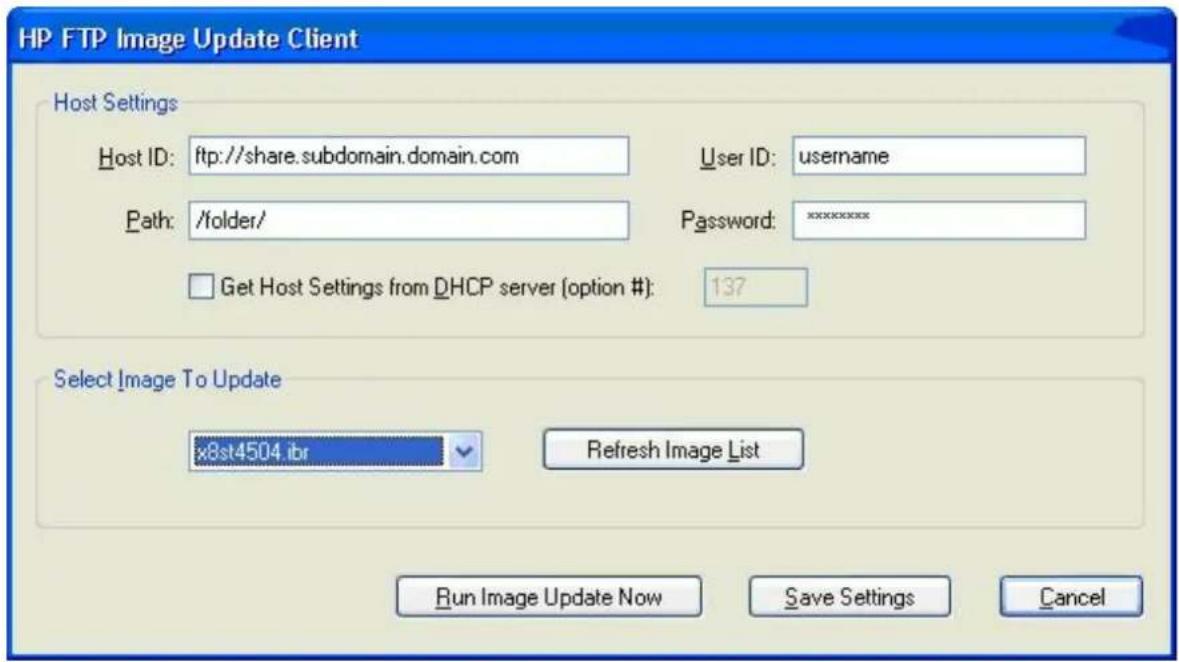
Host Settings
There are two ways to specify host settings:
- You can manually enter settings by clearing the Get Host Settings from DHCP server check box and filling in appropriate information to the Host ID, Path, User ID, and Password boxes.
If the FTP share allows anonymous read access, then you can leave the User ID and Password boxes empty.
If the WES images and WinPE image are stored in the default (root) folder on the FTP server, then you can leave the Path box empty or fill the box with I.
- Automatically through a DHCP option by selecting the Get Host Settings from DHCP server check box.
These host settings can be saved and committed by clicking on the Save Settings button. When the applet is invoked again, the settings will be retrieved and the corresponding controls are automatically populated.
Select Image to Update
Once the host settings are entered, either manually or automatically through DHCP, then click the Refresh Image List button to make the applet query the FTP share for all WES images whose targeted BIOS families match the one of the current thin client system, and fill in the drop-list combo box to the left of the button. You can choose any of the listed images to update/image the system.
When ready, you can click the Run Image Update Now button to proceed with the image update using the selected image. A confirmation dialog similar to the following is displayed.
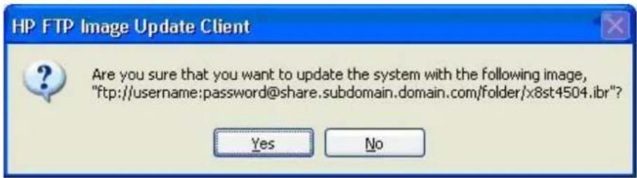
Click No to abort the operation. If you click Yes, the HP FTP Image Update Client confirms that the flash drive has at least 200MB free to host the WinPE image. If the flash drive does not, the following error message is displayed.
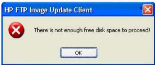
If the flash device has enough memory, the update client starts the download of the WinPE image, modifies the boot loader to boot to WinPE in the next system restart, and then restarts the system to continue to the WinPE phase.
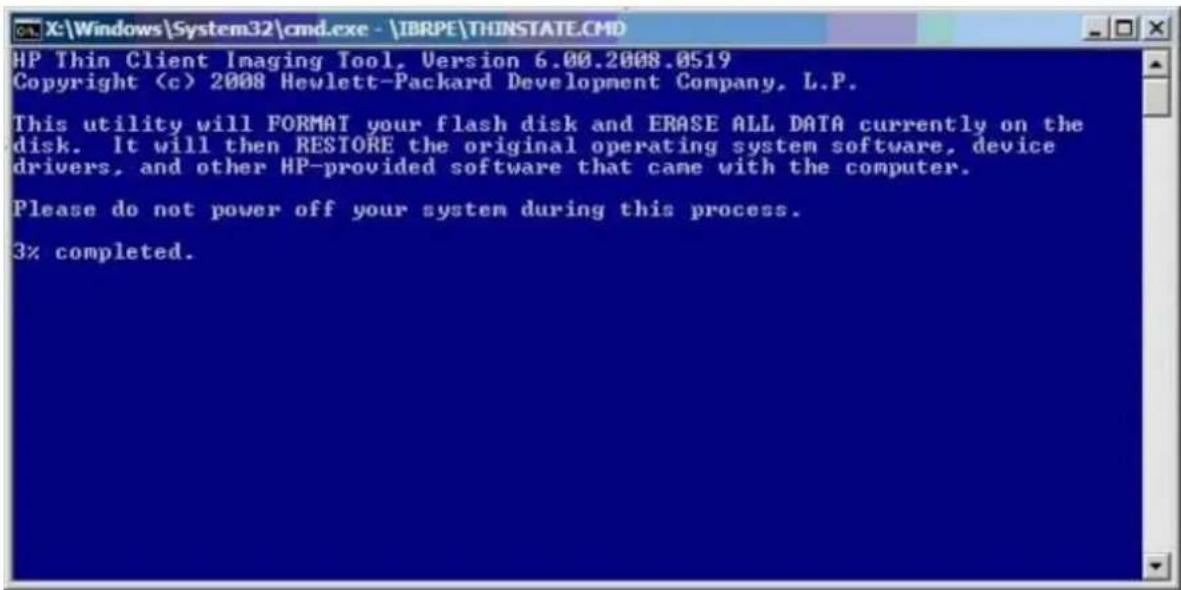
Please wait... HP FTP Image Update Client is preparing the system for image update. Once done, it will restart the system to continue with the update process.
Once WinPE is loaded, IBRPE is spawned to image the system's flash drive using the selected image from the FTP share. When the imaging completes, IBRPE automatically restarts the system to enter the FBA phase.
D S y s t e m B I O S
Restoring or updating a BIOS
If the BIOS on the thin client is corrupt, the BIOS must be restored before the thin client will boot to the operating system.
To update the system BIOS, download the Softpaq (for the product being updated) from the HP Web site.
The Softpaq contains utilities for restoring or updating the system BIOS. Included in the Softpaq are several methods for changing or updating the BIOS version on your computer.
To determine the BIOS family, version, and date on the thin client, press F10 during system power-on to run the F10 Setup utility, then select System Information.
To update or restore a BIOS:
- Go to http://www.hp.com.
- Select Support and Drivers.
- Type the model number of your thin client.
- Click the link for your thin client model.
- Click Download drivers and software.
- Click the link for your thin client model.
- Select your language, and then click the link for your operating system.
- Select the update you want to apply.
- Download the Softpaq to a directory on your hard drive. The downloaded file is a self-extracting executable.
- From that drive and directory, execute the downloaded file and follow the on-screen instructions.

WARNING! Do not turn off power or attempt to reboot the computer during the upgrade process.
Electrostatic Discharge
A discharge of static electricity from a finger or other conductor may damage system boards or other static-sensitive devices. This type of damage may reduce the life expectancy of the device.
Preventing Electrostatic Damage
To prevent electrostatic damage, observe the following precautions:
- Avoid hand contact by transporting and storing products in static-safe containers.
- Keep electrostatic-sensitive parts in their containers until they arrive at static-free workstations.
- Place parts on a grounded surface before removing them from their containers.
- Avoid touching pins, leads, or circuitry. Always be properly grounded when touching a static-sensitive component or assembly.
Grounding Methods
There are several methods for grounding. Use one or more of the following methods when handling or installing electrostatic-sensitive parts:
- Use a wrist strap connected by a ground cord to a grounded Thin Client chassis. Wrist straps are flexible straps of 1 megohm +/- 10 percent resistance in the ground cords. To provide proper grounding, wear the strap snug against the skin.
- Use heelstraps, toestraps, or bootstraps at standing workstations. Wear the straps on both feet when standing on conductive floors or dissipating floor mats. Use conductive field service tools. Use a portable field service kit with a folding static-dissipating work mat.
If you do not have any of the suggested equipment for proper grounding, contact an HP authorized dealer, reseller, or service provider.

NOTE: For more information about static electricity, contact an HP authorized dealer, reseller, or service provider.
F Specifications
Table F-1 HP t505 Flexible Thin Client
| Dimensions | ||
| Width | 50.00 mm | 1.97 in. |
| Height (without stand) | 220.00 mm | 8.66 in |
| Height (with stand) | 228.50 mm | 9.00 in |
| Depth | 194.00 mm | 7.74 in. |
| Approximate Weight (without adapter) | 1.483 kg | 3.27 lb |
| Adapter | 0.336 kg | 0.74 lb |
| Temperature Range (fanless design)* | ||
| Operating** | 10° to 35°C | 50° to 95°F |
| (max. rate of change is 10°C per hour or 18°F per hour) | ||
| Nonoperating | -30° to 60°C | -22° to 140°F |
| (max. rate of change is 20°C per hour or 36°F per hour) | ||
| *Specifications are at sea level with altitude derating of 1°C/300 m (1.8°F/1000 ft) to a maximum of 3 Km (10,000 ft), with no direct, sustained sunlight. Upper limit may be limited by the type and number of options installed. | ** The operating temperature range when the thin client is attached to a flat panel using the HP Quick Release is 50° to 95°F (10° to 35°C). | |
| Relative Humidity (non-condensing) | ||
| Operating | 10–90% | 10–90% |
| (max. wet bulb temperature is 28°C or 84.2°F) | ||
| Nonoperating | 5–95% | 5–95% |
| (max. wet bulb temperature is 38.7°C or 101.6°F) | ||
| Maximum Altitude (unpressurized) | ||
| Operating | 3048 m | 10,000 ft |
| (max. allowed rate of change is 457 m per minute or 1500 ft per minute) | ||
| Nonoperating | 9144 m | 30,000 ft |
| (max. allowed rate of change is 457 m per minute or 1500 ft per minute) | ||
| Power Supply | ||
| Operating Voltage Range | 100–240 VAC | 100–240 VAC |
| Rated Line Frequency | 50–60 Hz | 50–60 Hz |
| Power Output (maximum) 65 W 65 W | ||
| Rated Output Current (maximum) 3.42 A 3.42 A | ||
| Output Voltage +19 V DC +19 V DC | ||
Index
A
access panel
removing 8
replacing 9
adding an image restore tool 52
altitude specifications 62
authorizing Remote Installation Services 53
B
basic troubleshooting 29
battery, replacing 10
beep codes 28
BIOS 60
restoring 60
updating 60
C
cable routing slot 4
cautions
static electricity 7
changing BIOS settings
in the reset utility 21
using the F10 utility 22
components
front panel 3
rear panel 4
configuring a PXE server 53
configuring Remote Installation Services 54
D
description 1
diagnostics and troubleshooting 26
dimensions 62
diskette drive 11
diskless troubleshooting 30
download hardware drivers 8
E
electrostatic discharge 61
Ethernet connector location 4
F
features 1
feet, installing 4
Flash activity LED location 3
formatting a flash drive 50
front panel components 3
G
grounding methods 61
H
hard drive 11
hardware drivers 8
hardware specifications 62
hardware, upgrades 7
headphone connector location 3
horizontal orientation 4
humidity specifications 62
|
image restore tool 52
installation sequence 7
installing
external drives 11
hardware 7
MultiBay diskette drive 11
rubber feet 4
stand 5
installing Remote Installation
Services 53
ISO image 50
L
LEDs 26
line-out audio location 4
M
microphone connector location 3
mounting holes, VESA 4
0
operating systems 1
options
installing 7
supported 7
orientation
horizontal 4
vertical 5
P
parallel connector 4
POST error messages 28
power and IDE flash activity LEDs 26
power button location 3
power connector location 4
power LED location 3
power output specifications 63
power supply specifications 63
power-on diagnostic tests 27
power-on sequence 27
powered serial ports locations 12
system board jumpers 12
preventing electrostatic damage 61
product description 1
PS/2 connectors location 4
PXE 51, 53
R
rated output current 63
rear panel components 4
recycling 10
relative humidity specifications 62
removing
battery 10
side access panel 8
stand 6
replacing
battery 10
side access panel 9
restore 52
restoring a corrupt BIOS 60
restoring the flash image 49
RIS menu 55
RJ-45 connector location 4
rubber feet, installing 4
S
secure cable routing slot 4
serial connector location 4
serial connectors 12
serial number location 2
setting user permissions on the
Active Directory Server 54
Setup Utility
Advanced BIOS Features 23
Integrated Peripherals 24
Main Menu 22
Power Management Setup 25
Standard CMOS Features 23
System Information 23
Utility Task Actions 25
shutting down 7
side access panel
replacing 9
specifications
altitude 62
dimensions 62
hardware 62
humidity 62
power output 63
power supply 63
rated output current 63
relative humidity 62
temperature 62
thin client 62
weight 62
stand
installing 5
removing 6
T
temperature specifications 62
troubleshooting 29
U
updating a BIOS 60
USB drive options 11
USB ports
location 3, 4
V
vertical orientation 5
VESA mounting holes 4
VGA connector location 4
W
warnings
electric shock 7, 8, 10, 13
fire 7
Web sites
QuickSpecs 1
weight 62

- TROUBLESHOOTING GUIDE
- HP T505 FLEXIBLE THIN CLIENT
- ABOUT THIS BOOK
- TABLE OF CONTENTS
- PRODUCT DESCRIPTION
- HARDWARE CHANGES
- BIOS SETTINGS, (F10) UTILITY
- DIAGNOSTICS AND TROUBLESHOOTING
- RESTORING THE FLASH IMAGE
- APPENDIX A ADDING AN IMAGE RESTORE TOOL
- APPENDIX B CONFIGURING A PXE SERVER
- APPENDIX C FTP UPDATE
- APPENDIX D SYSTEM BIOS
- APPENDIX E ELECTROSTATIC DISCHARGE
- APPENDIX F SPECIFICATIONS
- INDEX
- OPERATING SYSTEMS
- PRODUCT FEATURES
- SERIAL NUMBER LOCATION
- FRONT PANEL COMPONENTS
- REAR PANEL COMPONENTS
- INSTALLING THE RUBBER FEET
- INSTALLING THE STAND
- REMOVING THE STAND
- GENERAL HARDWARE INSTALLATION SEQUENCE
- REMOVING AND REPLACING THE SIDE ACCESS PANEL
- REMOVING THE SIDE ACCESS PANEL
- REPLACING THE SIDE ACCESS PANEL
- INSTALLING THIN CLIENT OPTIONS
- REMOVING AND REPLACING THE BATTERY
- EXTERNAL DRIVES
- CONFIGURING POWERED SERIAL PORTS
- USING THE BIOS SETTINGS
- CHANGING BIOS SETTINGS FROM THE RESET UTILITY
- CHANGING BIOS SETTINGS USING THE F10 UTILITY
- SETUP UTILITY—SYSTEM INFORMATION
- SETUP UTILITY—STANDARD CMOS FEATURES
- SETUP UTILITY—ADVANCED BIOS FEATURES
- SETUP UTILITY—INTEGRATED PERIPHERALS
- SETUP UTILITY—POWER MANAGEMENT SETUP
- SETUP UTILITY—UTILITY TASK ACTIONS
- LEDS
- POWER-ON SEQUENCE
- POWER-ON DIAGNOSTIC TESTS
- BEEP CODES
- POST ERROR MESSAGES
- TROUBLESHOOTING
- BASIC TROUBLESHOOTING
- DISKLESS (NO-FLASH) UNIT TROUBLESHOOTING
- TROUBLESHOOTING FLOWCHARTS
- INITIAL TROUBLESHOOTING
- ERROR MESSAGES
- NO AUDIO
- NO IP ADDRESS
- SYSTEM REQUIREMENTS
- GETTING STARTED
- CREATING AN ISO IMAGE
- FORMATTING A USB FLASH DRIVE
- UNPACKING THE IMAGE AND TOOLS FOR DEPLOYMENT
- DEPLOYING WITH PXE
- A ADDING AN IMAGE RESTORE TOOL
- B CONFIGURING A PXE SERVER
- PREREQUISITES
- INSTALLING REMOTE INSTALLATION SERVICES (RIS PXE SERVER)
- AUTHORIZING REMOTE INSTALLATION SERVICES (RIS PXE SERVER)
- CONFIGURING REMOTE INSTALLATION SERVICES
- SET USER PERMISSIONS ON THE ACTIVE DIRECTORY SERVER
- RIS MENU
- CREATING NETWORK BOOTABLE DISK TO MAP DRIVES
- FOR MORE INFORMATION
- C FTP UPDATE
- SERVER REQUIREMENTS
- DCHP SERVER
- FTP SERVER
- DESCRIPTION
- HOST SETTINGS
- SELECT IMAGE TO UPDATE
- D S Y S T E M B I O S
- RESTORING OR UPDATING A BIOS
- ELECTROSTATIC DISCHARGE
- PREVENTING ELECTROSTATIC DAMAGE
- GROUNDING METHODS
- F SPECIFICATIONS
- A
- B
- C
- D
- E
- F
- G
- H
- L
- M
- P
- R
- S
- T
- U
- V
- W
Brand : HP
Model : t505
Category : Thin client