ne8800 - Audio processor Ashly - Free user manual and instructions
Find the device manual for free ne8800 Ashly in PDF.


| Product Type | Network Enabled DSP Audio Processor |
| Model | ne8800 |
| Brand | Ashly |
| Input Channels | 8 line inputs (balanced Euroblock), optional mic/AES3/network audio |
| Output Channels | 8 line outputs (servo-balanced Euroblock), optional AES3 outputs |
| DSP Processing | 32-bit floating-point Sharc processor array |
| Sample Rates | 48 kHz, 96 kHz |
| Frequency Response | +/- 0.1 dB (20 Hz – 20 kHz, analog in to digital out) |
| Dynamic Range | >115 dB (20 Hz – 20 kHz, unweighted) |
| THD+N | <0.001% (1 kHz, +20 dBu analog in) |
| Latency | 1.42 ms at 48 kHz (analog in to analog out) |
| Controls | Ethernet (RJ45), RS-232, remote data port, 5 VDC remote control, 12V logic I/O |
| Remote Compatible | WR-5, neWR-5, RD-8C, RW-8C, FR-8, FR-16, WR-1, WR-1.5, WR-2, Ashly Remote iPad app |
| DSP Functions | Dynamics (compressor, limiter, gate, ducker, autoleveler, ambient noise compensation), EQ (graphic 31-band, parametric up to 10-band, feedback suppressor, FIR filter), crossover (2/3/4-way), delay (speaker and long delay), signal generator, matrix mixer, metering |
| Presets | Up to 30 device presets or sub presets |
| Word Clock | 75 ohm BNC, selectable termination, lock range 48 kHz ±4%, 96 kHz ±4% |
| Power Requirements | 90–240 VAC, 50–60 Hz, 70W maximum |
| Dimensions (W x H x D) | 19.0" x 3.5" x 8.5" (48.26 cm x 8.89 cm x 21.59 cm) |
| Weight | 10.5 lbs (4.77 kg) unit, 12.7 lbs (5.78 kg) shipping |
| Environmental | 40–120°F (4–49°C), non-condensing |
| Safety Compliance | FCC Part 15 Class B, must be earth grounded |
| Care & Maintenance | Keep dry; clean with a soft, dry cloth; do not use liquids or aerosols |
| Warranty | 5-year limited warranty (USA), factory service required |
| Spare Parts & Repairability | Contact Ashly or authorized service center; no user-serviceable parts inside |
Frequently Asked Questions - ne8800 Ashly
User questions about ne8800 Ashly
0 question about this device. Answer the ones you know or ask your own.
Ask a new question about this device
Download the instructions for your Audio processor in PDF format for free! Find your manual ne8800 - Ashly and take your electronic device back in hand. On this page are published all the documents necessary for the use of your device. ne8800 by Ashly.
USER MANUAL ne8800 Ashly
Network Enabled DSP Processor



ASHLY AUDIO INC.
847 Holt Road Webster, NY 14580-9103 Phone: (585) 872-0010
Toll-Free: (800) 828-6308 Fax: (585) 872-0739 ashly.com
The lightning flash with arrowhead symbol, within an equilateral triangle, is intended to alert the user to the presence of uninsulated "dangerous voltage" within the product's enclosure that may be of sufficient magnitude to constitute a risk of electric shock to persons. The exclamation point within an equilateral triangle is intended to alert the user to the presence of important operating and maintenance instructions in the literature accompanying the device
This device complies with part 15 of the FCC Rules. Operation is subject to the following two conditions:
- This device may not cause harmful interference
- This device must accept any interference received, including interference that may cause undesired operation
Note: This equipment has been tested and found to comply with the limits for a Class B digital device, pursuant to part 15 of the FCC Rules. These limits are designed to provide reasonable protection against harmful interference in both a commercial and residential installation. This equipment generates, uses and can radiate radio frequency energy and, if not installed and used in accordance with the instructions, may cause harmful interference to radio communications. However, there is no guarantee that interference will not occur in a particular installation. If this equipment does cause harmful interference to radio or television reception, which can be determined by turning the equipment off and on, the user is encouraged to try to correct the interference by one or more of the following measures:
- Reorient or relocate the receiving antenna.
- Increase the separation between the equipment and receiver.
- Connect the equipment into an outlet on a circuit different from that to which the receiver is connected.
- Consult the dealer or an experienced radio/TV technician for help.
- Increase the separation between the equipment and receiver. - Connect the equipment into an outlet on a circuit different from that to which the receiver is connected. - Consult the dealer or an experienced radio/TV technician for help.
Table Of Contents
1 INTRODUCTION ....4
2 UNPACKING ....4
3 THE NE PROCESSOR SERIES ....4
4 AC POWER AND MECHANICAL REQUIREMENTS ....5
5 GETTING STARTED ....5
6 FRONT PANEL FEATURES ....6
7 STANDARD BACK PANEL FEATURES ....7
8 OPTIONAL FEATURES ....8
8.1 Mic Input Channels....8
8.2 AES3 Input Channels ....8
8.3 AES3 Outputs ....8
8.4 Network Audio .... 8
9 PROTEA NE SOFTWARE ....9
9.1 Device Options 9
9.2 Preset Options....10
9.3 NE Processor Control Surface .....10
10 REMOTE CONTROL....11
10.1 WR-5 Programmable Zone Controller ..... 11
10.2 RD-8C or RW-8C Fader Control ..... 12
10.3 WR-1, WR-1.5, and WR-2 Remote Controllers....12
10.4 FR-8 and FR-16 Networked Fader Controller ..... 13
10.5 NE WR-5 Networked Programmable Controller ..... 13
11 SPECIFICATIONS ....14
12 TROUBLESHOOTING TIPS .....16
13 BLOCK DIAGRAM ....17
14 FACTORY INSTALLED INPUT/OUTPUT OPTIONS ....18
15 WARRANTY ....19
WARNING: THIS APPARATUS MUST BE EARTH GROUNDED THROUGH THE SUPPLIED POWER LINE CORD
1. INTRODUCTION
Thank you for your purchase of this NE (network enabled) processor. The ne8800, ne4800, and ne4400 combine state of the art DSP processing with Ethernet control, and use optional factory installed expansion cards to provide mic inputs, AES3 digital audio input/output, and full integration with Dante ^ or CobraNet ^ networked audio. Please read the entire manual to fully understand the features and capabilities of this product.
About Ashly
Ashly Audio was founded in 1974 by a group of recording engineers, concert sound professionals, and electronics designers. The first products were elaborate custom consoles for friends and associates, but business quickly spread to new clients and the business grew. The philosophy we established from the very beginning holds true today: to offer only the highest quality audio tools at an affordable cost to the professional user – ensuring reliability and long life. Many years later, Ashly remains committed to these principles.
Ashly's exclusive Five Year, Worry-Free Warranty remains one of the most liberal policies available on any commercial-grade product. The warranty covers every product with the Ashly brand name, and is offered at no extra cost.
2. UNPACKING
As a part of our system of quality control, every Ashly product is carefully inspected before leaving the factory to ensure flawless appearance. After unpacking, please inspect for any physical damage. Save the shipping carton and all packing materials, as they were carefully designed to reduce to minimum the possibility of transportation damage should the unit again require packing and shipping. In the event that damage has occurred, immediately notify your dealer so that a written claim to cover the damages can be initiated.
The right to any claim against a public carrier can be forfeited if the carrier is not notified promptly and if the shipping carton and packing materials are not available for inspection by the carrier. Save all packing materials until the claim has been settled.
3. THE NE PROCESSOR SERIES
There are three processor models, each with line level inputs and outputs, a full suite of DSP processing functions, 10/100 Ethernet control, eight assignable 12V Digital Logic I/O ports, eight DC level control ports assignable to input or output levels, a RS-232 control port, and a remote data port for programmable controllers such as the Ashly WR-5 and RD-8C.
Base Models:
ne4400 - Four line inputs, four line outputs
ne4800 - Four line inputs, eight line outputs
ne8800 - Eight line inputs, eight line outputs
In addition to the base model features, models can be custom ordered with various combinations of mic preamp inputs, AES3 inputs and outputs, plus Dante or CobraNet network audio.
4. AC POWER AND MECHANICAL REQUIREMENTS
The AC mains requirement for the NE Processor is 90VAC to 240VAC, 50-60Hz, 70W maximum, and requires a properly grounded AC connection. The unit mounts to a standard 19 inch equipment rack. A cooling fan draws air in from the right side and blows air out the left side when viewed from the front.
5. GETTING STARTED
Download the software
Ashly Protea NE software is no longer included on a CD with each unit. Check the Ashly web site at www.ashly.com to download the latest software release. Autorun will launch the application
Connect to Ethernet
The Ethernet control connection is made using an RJ-45 terminated eight conductor cable connected directly to a computer or indirectly over a standard 10/100M Ethernet network. Maximum cable distance for Ethernet is 100 meters from the nearest hub or switch for copper twisted pair CAT5 cable. For more detailed information about the proper implementation of an ethernet network, review one of the many comprehensive Ethernet networking guides available on the internet.
Identify the processor in software
Once the software is loaded to the computer and an Ethernet connection has been made to the NE processor, all Ashly NE products installed on that network will be automatically detected and shown in the active device listing on the left side of the Protea software startup canvas. In addition to detecting which models are currently online, any factory installed options (mic preamps, AES3, CobraNet) are auto-detected and the software control surface for the new NE product automatically displays available controls for the options present. Note: In the event of multiple processors of the same model on the network, the user can find a single physical unit by right clicking over the unit's name in the drop down menu or picture on the canvas, and then click
The software scans for active NE devices on power-up, but the user can manually scan at any time as well with
The NE system project canvas
The project canvas is used to visually represent and control a fixed physical sound system installation, and can display any of the Ashly NE processors, amplifiers, and remotes used in that system. The user can also place individual control objects such as level faders, single LEDs, meter bars, etc, and assign them to specific product functions within that project. Once a control object is placed, right click on it to bring up its properties. Lines, rectangles, text, even image files can be added to create a custom virtual control screen along with the NE products and individual control objects. To see all available canvas tools, right click anywhere over open canvas. Checking
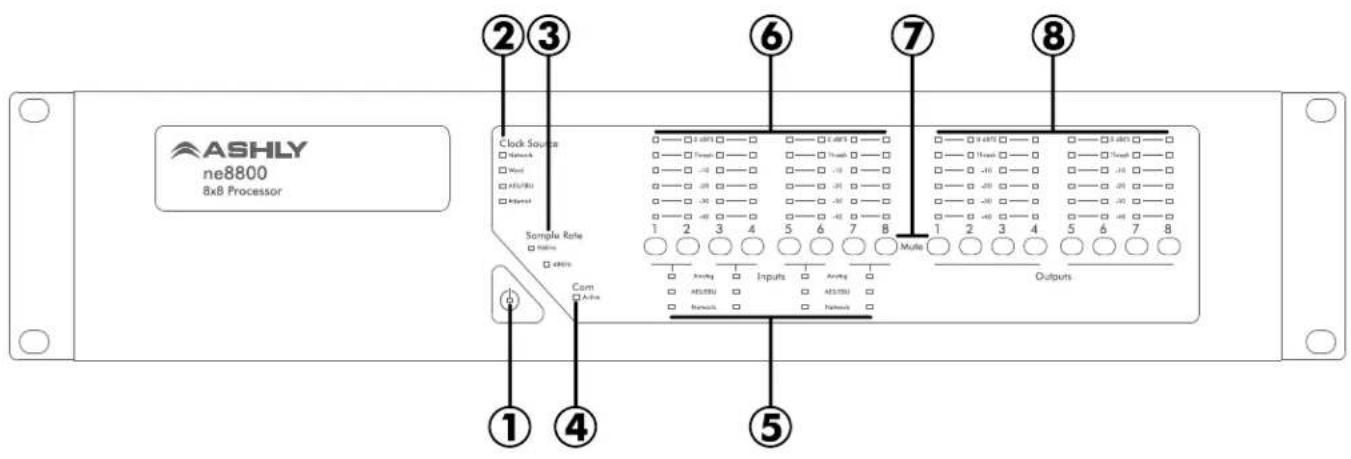
6. FRONT PANEL FEATURES
- Power LED - Indicates the unit is turned on.
- Clock Source – The Network clock, Word clock, AES3 clock, or Internal clock are indicated according to the master clock source selected in the control software. The Network clock LED turns orange when Net Matrix Mode is enabled.
- Sample Rate - 48KHz or 96KHz sampling rate may be selected from software. Also during flash reprogramming, both sampling rate LEDs will light amber for the duration of the procedure.
- Com LED – The Com LED indicates that data is being sent or received via the Ethernet control port. The Com LED can also be made to flash on for two seconds to visually identify a physical unit from within the software.
- Input Source – If more than one type of input is available for a given channel pair, an input source selection tab is available in software. The user can select an input pair source as analog (line input), analog (mic preamp), AES3 input, network audio, as well as set the input source selection to auto detect digital audio sources while automatically switching back to analog input when no AES3 or network audio signals are present. Green LED color = “Selected”, Red = “Not Valid”, and Off = “Not Being Used”.
- Input Level Meters - Input LED level meters display the signal level at the A/D converter before the DSP section. Levels displayed on the front panel are measured in dBFS (Decibels Full Scale), where 0dBFS is the maximum level possible, or true clipping. Software meter displays can be assigned as dBFS, dBu, or VU, but the front panel meters are always dBFS. The Threshold LED is used for dynamics functions configured in the DSP Controls section of the software.
- Input/Output Mute— This button is pressed to mute the input or output channel, and will additionally update that channel's mute status as shown in software. Green means the channel is unmuted, while red means the channel is muted and will not pass audio. For security, all front panel mute controls can be disabled from within software under
, then . If a mic input channel is set up for the push to talk function using logic I/O pins, that channel's mute button will illuminate orange to indicate push to talk status, and turn green whenever the mic button is pressed. - Output Level Meters - Like the input meters, output meters reference 0dBFS, meaning 0dBFS is the true clipping point, and are measured from the D/A converter point after the DSP section.
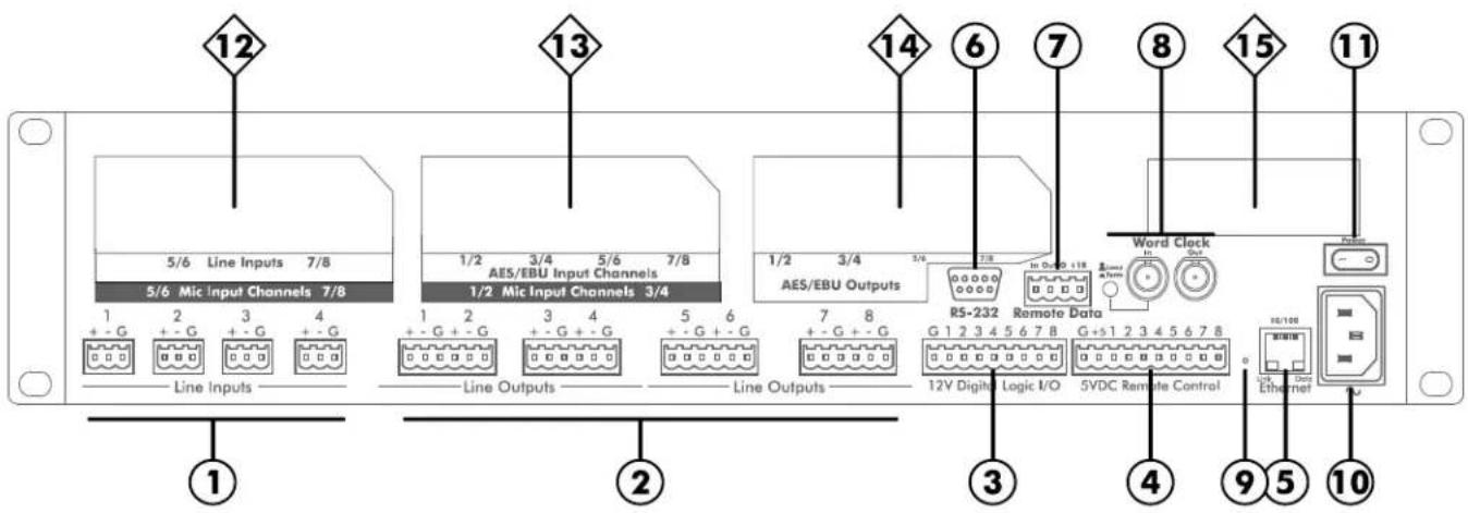
⑦ STANDARD BACK PANEL FEATURES
-
Line Inputs - Depending on the model, there are either four or eight line inputs available. Line inputs are active balanced with euroblock connectors. If an unbalanced signal is used, connect the unused input pin to ground. Maximum input level is +20dBu = FS (full scale).
-
Line Outputs - Depending on the model, there are either four or eight line outputs available. Line outputs are servobalanced with euroblock connectors, and may be wire balanced or unbalanced, with a maximum output level of +20dBu FS.
-
12V Digital Logic I/O - All models have a nine pin curoblock connector for logic inputs or outputs. The Logic I/O tab in software allows logic pins to be assigned as either logic inputs or logic outputs. Logic input "high" range is from +2.3VDC to +25VDC (do not exceed +25VDC). Logic inputs can be assigned to trigger a preset recall or push-to-talk mic function from contact closure. Logic pins can also be assigned as current-limited 12V logic outputs, triggered by a preset recall or WR-5 button for control of 12V or 5V external devices. See page 11 for more logic pin details.
-
5VDC Remote Level Control - All models have a 10 pin curoblock connector for accommodating up to eight user defined remote DC level controls. Use an Ashly WR-1 remote attenuator (or equivalent 10K potentiometer), along with a remote gain block placed within the software DSP section to assign remote level control to any channel's input or output section. Wire the 5VDC Remote Control ground to the CCW pin of the remote control potentiometer, wire +5 to the CW pin, and wire the control pin (1-8) to the potentiometer wiper.
-
Ethernet Jack - This is the RJ-45 connector used for 10/100 ethernet control. Maximum cable distance to the nearest computer, hub, or switch using CAT5 twisted pair copper cable is 100 meters.
-
RS-232 Jack - This connector is for remote control by non-Ethernet based hardware that uses RS-232 control data protocol. A complete NE RS-232 protocol document is available on the Ashly website.
-
Remote Data - This is used to connect a remote WR-5 programmable button controller or RD-8C fader controller.
-
Word Clock - If two pieces of digital audio gear need to be synchronized, i.e. their sample rates are very slightly different and must be made to match exactly, word clock synchronization is necessary to avoid sample skipping. Additionally, when several pieces of gear are cascaded in an AES3 digital audio chain, each digital audio input adds some small amount of clocking jitter and perhaps sample delay. After several units, the cumulative jitter could cause a loss of lock (and hence loss of audio), increased distortion due to large amounts of jitter, or even a small delay. By connecting a master word clock to each device, they all become precisely synchronized.
The NE processor defaults to “Auto Selection” which automatically detects a Network, Word Clock, AES3, or Internal master clock source and automatically switches, in this order of priority. Therefore, in most system configurations, the user doesn’t need to worry about the master clock source, the processor will automatically pick the best master clock from the highest priority available. The processor will mute all audio outputs for about one second when it switches master clock sources. This Auto Selection mode can be over-ridden in the control software by clicking on
The word clock switch on Ashly equipment provides two functions. First, it routes the word clock input signal hard-wired looped-through to the word clock output jack when in the OUT (Loop) position, but breaks the signal and generates an internal word clock source in the IN (Term) position. Secondly, the OUT position does not apply any load to the looped-through word clock signal, but the IN position applies a 75 ohm termination to the word clock input and supplies a 75 ohm source impedance to the word clock output. Therefore, the word clock switch should be in the IN “term” position whenever the unit is at either end of the word clock line, and in the OUT “loop” position when placed anywhere else along the line. No external terminations are needed.
-
Factory Reset - To reset the NE processor to original factory settings and permanently erase all stored preset data from the unit, use a paper clip or similar object to depress the recessed switch and hold for six seconds during power up. Factory reset is complete when all channel LEDs on the face panel are lit.
-
AC Inlet - 90-240 VAC, 50-60Hz, 70W, detachable AC cord. Do not remove or lift the mains connector ground.
-
Power Switch - This switch applies and removes power to the unit.
8 OPTIONAL BACK PANEL FEATURES
- Mic Input Channels - High performance mic inputs are available as factory installed options for channels 1-4, and/or 5-8. Mic input connections are balanced curoblock, with switchable +48V phantom power. When a mic preamp option is installed, the tab appears in the software and represents the mic preamps as available input sources with an icon labelled
. Mic preamp gain of 0dB, +20dB, +40dB, or +60dB is set in the input source menu by clicking on the preamp icon for a given channel and checking the appropriate gain.
Some microphones in paging applications have a button/switch which the user must push in order to use the microphone. This button acts as a contact closure which is wired to a logic input and used to control mute and ducking functionality. When thebox is checked in the input preamp section, that channel's mic will only be unmuted when the assigned logic pin's contact is closed (the button is pressed). Note: the push to talk mic feature mutes the mic channel and indicates its status by turning the mute button orange. Manual mute will still override the push-to-talk unmuting of that channel. Also, if that mic is also a ducking trigger, it will trigger the ducked channel level reduction immediately, regardless of the mic input level. - AES3 Input Channels - AES3 (AES/EBU) is a digital audio format where two channels of digital audio are transmitted over a standard mic cable. Depending on the option installed, the AES3 input expansion card receives four or eight channels of audio which can then be routed, processed, and distributed. When an AES3 input is installed, the input source select tab allows for exclusive selection of AES3 input, as well as selection of AES3 with analog backup in the event there is no digital input signal. AES3 has a cable length limitation of about 100 meters depending on cable type and impedance ratings. Refer to the AES3 specifications for detailed line impedance and impedance matching information.
- AES3 Outputs - AES3 outputs, if installed, always carry the exact same audio signals as the line outputs, except in AES3 format. There is no access to AES3 outputs in software.
- Network Audio Card - Ashly currently supports Dante and CobraNet network audio options, offering a full featured audio interface portal into or out of the larger audio network. See the NE software section on network audio for further implementation details.
9. PROTEA ^ne SOFTWARE
Device Options Menu
Flash Reprogram
The NE processor firmware (the internal program that runs the unit) can be updated/reprogrammed via the Ethernet control connection. The latest firmware file can be downloaded from our web site, and installed according to the
Link Configuration
Linking allows multiple DSP processing blocks on different channels or even different Ashly NE devices to track each other. For example - if two graphic equalizers on different channels are linked, any change made to one of the equalizers will result in an identical change to the other. Most DSP blocks can be linked to one of eight link groups. When a DSP function is assigned to a link group, both a colored tab and the link group number appear beneath the DSP block icon. The link group's tab color, group name, and local/network (link across devices) status is assigned in the link configuration dialogue box. Note: If a WR-5 or RD-8C is connected to a NE device, and a DSP function that can be controlled by the WR-5 or RD-8C (such as gain) is linked across multiple devices, changes made by that WR-5 or RD-8C will only affect it's host NE device. Linked changes across devices must come from the NE software, not remotes.
Meter Display
Software meter displays can be set to VU, dBu, or dBFS (dB Full Scale). dBFS is typically used when all or most of the gain/level adjustments occur in the DSP domain. The front panel LEDs on the NE processor are dBFS only and cannot be changed to dBu or VU. For comparison, 0 dBFS is the same as +20dBu on a product which clips at +20dBu. Therefore, -20dBFS is typically the desired operating range, while still allowing 20dB headroom for transient signals.
AES3 Receiver Status
With a four or eight channel AES3 input option installed, each stereo AES3 input can be monitored for detected sample rate error and other data errors that may occur between the AES3 source and the NE processor input. This can be useful for diagnosing problems in either communication setup or wiring. Any errors detected by the NE processor are latched, meaning even an intermittent error will be detected and remain highlighted until the
Sample Rate and Master Clock Selection
This screen displays the current master clock source, current sample rate, and word clock status. Click on
Disable Front Panel Mutes
This control prevents the NE processor mute buttons from functioning. Mute status can still be controlled from software.
DVCA Control
One of the DSP Gain block functions is called
DSP Enable/Disable Control
The user can disable DSP functions on selected inputs, outputs, or the entire mixer to free up DSP processing power.
Network Audio Matrix
The network matrix input/output functions allow the NE processor to be integrated into a larger digital audio network. With CobraNet, the NE processor can selectively route incoming line, mic, or AES3 signals, including DSP processing, out to the CobraNet network using the network matrix. Likewise, individual CobraNet network channels can be selected and routed (through DSP) to the analog or AES3 outputs of the NE processor. With Dante, the net matrix input does not offer selective matrix routing, that job is performed using the Dante Controller. Dante net matrix output channels can be assigned in the software using the DSP output mixer, or by using Dante Controller.
Preset Options
Presets and Sub Presets
The NE processor will store up to 30 device presets or sub presets. A device preset takes a “snapshot” of the most common audio settings and stores control data for all channels and all audio functions. A sub preset, although in the same format as the full preset file, scans for and only stores the DSP parameters individually tagged as sub presets within each DSP tool box, within one channel or across multiple channels. Sub Presets are thus used to change only the selected functions. When naming presets or sub presets, indicate in the preset name if it is a sub preset, this will help later when assigning the sub preset to a recall event such as contact closure or WR-5 control. Individual presets (or sub presets) can be saved to the processor by using
A preset or sub preset file can be recalled from either a computer or from the processor's internal memory. An installation can be set up so that an Ashly WR-5 active programmable remote, or a contact closure, triggers the recall of presets or sub presets stored in the NE processor. For contact closure preset recall, use the software Logic I/O tab to assign one of 30 presets or sub presets to one of the eight digital logic input pins on the processor's back panel. For Ashly WR-5 preset management, connect the WR-5 to the NE processor and use the WR-5 device in software to assign device and preset (or sub preset) controls. Caution: A new preset may have dramatically different settings capable of damaging sound system components, so be careful not to recall the wrong preset while the system is on.
The NE Processor Control Surface
Input Source
The input source tab displays all available inputs to the NE processor per channel pair, and allows the user to select which input type and in what priority those inputs are to be used. Also shown is the current master clock and sampling rate.
Net Matrix Mode: If a network audio card is installed, and
DSP Controls
All of the DSP control is done in the DSP tab. If additional network audio is available to the DSP processor, select the
Dynamics: Brick Wall Limiter, Compressor, AutoLeveler, Ducker, Gate, Ambient Noise Compensation (outputs only)
Gain: Gain, Gain with VCA, Remote Gain, and WR-5 Remote Gain
Equalization: Graphic 31 band, Parametric EQ with 10, 6, 4, or 2 band, Feedback Suppressor (inputs), FIR filter (outputs)
Crossover: HPF and LPF on both inputs and outputs, 4 Way, 3 Way, or 2 Way Crossover on outputs only
Delay: Speaker Delay (0-58mS), Delay (0-1.365mS)
Tools: Audio Meter (0 to -80dBFS), Signal Generator (pink noise, white noise, sinewave)
Metering
Three separate metering tabs are available for viewing the autoleveler, compressor/gate actions, or overall input and output signal levels across all channels. Note: In addition to the fixed meter tabs, individual meter control objects can be placed on the main software canvas and assigned to an input or output for a custom meter display.
Logic I/O
This tab is where the 12V digital logic I/O pins on the NE processor's back panel are assigned function. Pins designated as logic inputs, upon contact closure with the logic ground, can recall a preset, utilize 'push to talk' to unmute a mic input and trigger a ducker, or be assigned no function. Do not wire contact closure switches to any external ground. If a logic input pin is unconnected, it will be internally pulled high. If a logic input pin is driven from an external source, any voltage from +2.3V to +25V will be detected as logic high. Do not exceed +25V or damage may occur to the internal circuitry.
Pins designated as logic outputs will issue either a logic high level (+12V source at 10mA) or logic low level (0V sink at 100mA) when the GPO function (general purpose output) is selected. The high or low output state is a function of the currently loaded preset, or can be the result of a WR-5 button programmed to set the logic output to active high or active low. The logic outputs are current limited to sourcing no more than 10mA so that these outputs can be directly wired to LED indicators.
Security
The security tab allows several levels of user ID/password protected access. The default user ID is Admin, with no password until the principle operator enters one. Up to six additional users can be added, each with their own password and access rights assigned by the Admin.
Network Properties
This is where to find the current hardware and firmware configuration of a specific NE processor, as well as network details. Also found here is an
10. REMOTE CONTROL (check the Ashly website for updated or additional remote control models)
10.1 WR-5 Programmable Zone Controller
The WR-5 is a microprocessor based programmable remote control unit which can be used with the NE processor. The WR-5 is designed to fit into a standard US electrical wall box. Up to four WR-5 remotes can be phantom powered from one NE processor. Additional remotes can be powered by using the Ashly RPS-18 remote power supply. Each of six buttons on the WR-5 can be programmed to engage one of the following functions listed below. The up/down buttons are used to adjust the function property.
1) Preset Recall
2) Preset Scroll Mode
3) Gain Control
4) Channel Engage/Mute
5) Zone Source Selection
6) Logic Output Active High
7) Logic Output Active Low
8) Matrix Mixer
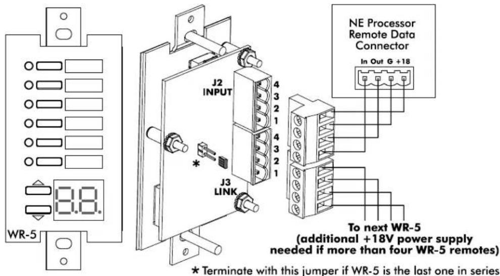
Ashly WR-5 Programmable Controller
(10.1 WR-5 continued)
Programming of each WR-5 button is done after the WR-5 is wired to its host NE processor through the remote data connector and the NE processor is networked to a PC running Protea™ software. Each WR-5 has its own identifying property and is uniquely represented with its own software control surface. Click the
10.2 RD-8C or RW-8C Remote Fader Control
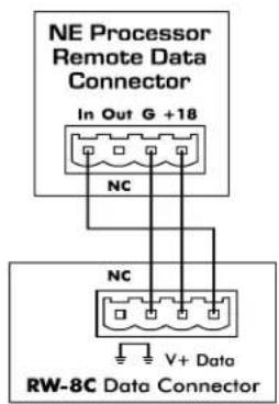
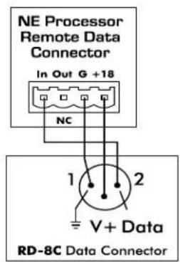
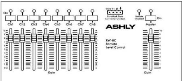
A second microprocessor based desktop controller, the Ashly RD-8C (or RW-8C wall mount), is an eight channel level controller that uses slide faders for individual channel and master level control and mute. The RD-8C is wired to the four pin Data Input euroblock connector on the back panel. Only one RD-8C can be wired to a NE processor. NOTE: When an RD-8C is used, no other serial data type remotes can be used.
In the software DSP section, a remote gain function must be placed in any input or output and then assigned to one of the RD-8C slide faders for remote level control of that channel. The RD-8C uses an XLR jack, while the RW-8C uses a euroblock connector to wire to the NE processor (see wiring diagram).
flowchart
graph TD
    A["On"] --> B["Ch1"]
    B --> C["Ch2"]
    C --> D["Ch3"]
    D --> E["Ch4"]
    E --> F["Ch5"]
    F --> G["Ch6"]
    G --> H["Ch7"]
    H --> I["Ch8"]
    I --> J["Gain"]
    K["Ch1"] --> L["Gain"]
    M["Ch2"] --> N["Gain"]
    O["Ch3"] --> P["Gain"]
    Q["Ch4"] --> R["Gain"]
    S["Ch5"] --> T["Gain"]
    U["Ch6"] --> V["Gain"]
    W["Ch7"] --> X["Gain"]
    Y["Ch8"] --> Z["Gain"]
    AA["Ch1"] --> AB["Gain"]
    AC["Ch2"] --> AD["Gain"]
    AE["Ch3"] --> AF["Gain"]
    AG["Ch4"] --> AH["Gain"]
    AI["Ch5"] --> AJ["Gain"]
    AK["Ch6"] --> AL["Gain"]
    AM["Ch7"] --> AN["Gain"]
    AO["Ch8"] --> AP["Gain"]
    AQ["Eutelock Data Converter On Back"] --> AR["Ch1"]
    AS["Remote Disabled"] --> AT["Ch1"]
    AU["Master"] --> AV["Ch1"]
    AW["ASHLY"] --> AX["RW-BC"]
    AW --> AY["Remote"]
    AW --> AZ["Level Control"]
Ashly RW-8C Remote Level Controller
10.3 WR-1 Remote DC Level Control
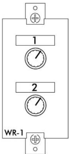
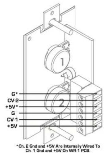
Individual input or output channels can have remote level control using a potentiometer assembly such as the Ashly WR-1 and four conductor bell wire. The WR-1 is a dual potentiometer remote volume control designed to fit in a standard US electrical wall box. Each volume control is connected to a terminal block on the WR-1 circuit board, which is then wired to the processor back panel euroblock connector labeled "5VDC Remote Control" as shown. Do not connect the WR-1 remote level control ground to any other external grounds.
10.4 WR-1.5 Level and Preset Recall (not shown)
The WR-1.5 offers a four position rotary switch for preset recall along with a single potentiometer for DC level control. See our website for further details.
10.5 WR-2 Pushbutton Preset Recall (not shown)
The WR-2 offers four pushbutton switches for recalling device presets by wiring to the NE processor logic inputs and assigning them preset recall function. See our website for WR-2 details.
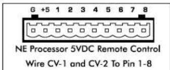
Ashly WR-1 Remote DC Level Controller
10.6 FR-8 and FR-16 Networked Fader Controller
The FR-8 (shown) and FR-16 (not shown) are eight and 16 channel programmable fader remote control devices which connect to the NE processor over an Ethernet network. Each fader can be assigned in Protea ^te software to control level in one or more channels. A pushbutton LED switch associated with each fader shows signal level/clip for audio signals controlled by that fader and can be assigned mute function or A/B source select for that fader. The FR-8 and FR-16 devices can mount to a wall box, panel cutout, or remain freestanding.
Power is from an IEEE 802.3af Power over Ethernet (PoE) switch, hub, or in-line PoE injector. A back panel lockout connection is available to disable all controls using a key switch.
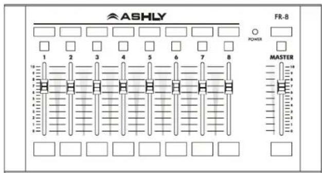
Ashly FR-8 Networked Programmable Fader Controller
The FR-8 or FR-16 appears in the Protea ^ne software device network tree and must be assigned to the NE processor under control. Labels can be inserted behind the mylar overlay to properly identify custom programmed fader and button functions.
10.7 neWR-5 Networked Programmable Button Controller
The neWR-5 remote control is a networked version of the WR-5, using Ethernet instead of the Data Port to communicate with the NE processor. Connecting and powering the neWR-5 is done using Cat-5 Ethernet cable and an IEEE 802.3af Power over Ethernet (PoE) switch, hub, or in-line PoE injector. If PoE is unavailable, the Ashly RPS-18 (sold separately) is a 15-48VDC power supply capable of at least 2 watts per ncWR-5 and can be hard wired to the back of the ncWR-5. PoE current draw is 38mA @48VDC and 80mA@15VDC. A decora cover plate (not included) can be purchased at hardware stores to cover the neWR-5 electrical box and satisfy the aesthetic needs of the installation.
The neWR-5 appears in the Proteane software device menu tree and must be assigned to the NE processor under control. The neWR-5 has six programmable function buttons which can light up green, red, or amber to display status. Further information on LED status is found in the neWR-5 owner's manual available on the Ashly website. To the right of the function buttons is a pocket in the mylar overlay for a printed function label (template available on website) to be inserted. The two other buttons are used to adjust function parameters such as gain or preset number, and are indicated by the LED display.
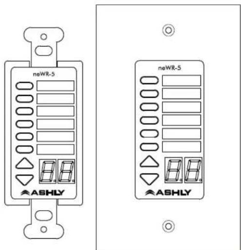
Ashly neWR-5Networked Programmable Button Controller
There is also a hard-wired Lock-Out feature on the neWR-5, where the closing of a switch wired to the lockout Euroblock renders all buttons inactive.
10.8 Ashly Remote App for iPad®
A custom and secure touch-screen control surface for the iPad can be designed using the
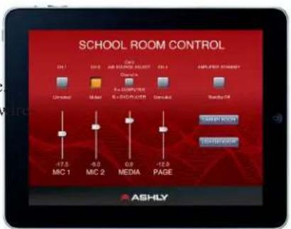
- SPECIFICATIONS Note: 0dBu = 0.775Vrms, 0dBFS (dB full scale) = +20dBu
| Overall Sonic Performance | Analog in, digital out | Digital in, analog out | Analog in, analog out^1 | Digital in, digital out |
| Frequency Response, 20 Hz - 20 kHz: | +/- 0.1 dB | +/-0.25 dB | +/- 0.25 dB | NA^3 |
| Dynamic Range, 20Hz-20kHz, unweighted: | >115 dB | >114 dB | >114 dB | NA^3 |
| THD+N, 1kHz, +20dBu analog (-1dBFS digital): | < 0.001 % | < 0.002 % | < 0.002 % | < 0.00001 % |
| Latency at 48 kHz (96 kHz) ^4 : | 1.42 ms (0.71 ms) | 0.90 ms (0.45 ms) | 2.21 ms (1.11 ms) | 0.10 ms (0.05 ms) |
Notes: 1) Measured 20 Hz - 20 kHz unweighted using AES17 LPF at 48 kHz sample rate.
2) Analog in to analog out measured using internal master clock.
3) Zero noise or signal amplitude variation introduced in digital domain.
4) Latency of network audio link is additional to latency of digital audio processor.
| Audio Inputs | Analog Line/Mic | AES3 Digital |
| Input Type: | Active balanced Euroblock | Transformer balanced female XLR |
| Input Impedance: | 20k ohms | 110 ohms |
| Max Input Level: | +20 dBu | 7.0 Vpp |
Audio Outputs
| Output Type: | Servo-balanced Euroblock | AES3 Transformer balanced male XLR |
| Output Impedance: | 20 ohms | 110 ohms |
| Max Output Level: | +20dBu | 5.0 Vpp |
Word Clock
| Input/output Type: | 75 ohm BNC |
| Lock Range: | 48 kHz +/- 4%, 96 kHz +/- 4% |
| Input Impedance: | Selectable 75 ohm or high-impedance |
| Input Voltage Range: | 1.0 Vpp – 7.0 Vpp |
| Output Impedance: | 75 ohm |
| Output Level: | 5.0 Vpp nominal, unterminated |
Master Clock
| Sources: | Audio network, Word clock, AES3, Internal crystal clock |
| Modes: | Prioritized auto switching or manual |
Digital Audio Hardware
| Samples Rates: | 48 kHz, 96 kHz |
| DSP Processing: | 32-bit floating-point Share® processor array |
| Audio Input Source Selection: | Selectable in adjacent channel pairs from analog, digital, or network inputs |
| Network Audio Routing: | Selectable between input/output or internal to matrix mixer |
| Digital Audio Output Jitter: | 0.5 ns average, 1.0 ns peak |
Remote Control
| Ethernet Control | Standard RJ45 10/100 Ethernet with auto-configuration |
| RS-232 Control | Standard female Dsub9 jack (RS-232 control protocol document for Ashly NE products available on Ashly website) |
| 4-pin active remote | 4-pin Euroblock for phantom-powered bi-directional remotes |
| Logic Inputs (up to eight) | 9-pin Euroblock for assignable logic inputs. Detected logic high range is from +2.3V to +25V. Do not exceed +25V. |
| Logic Outputs (up to eight) | Shared pins with logic inputs. Source: +12V at 10mA for logic output high. Sink: 0V at 100mA for logic output low. |
Analog Control
| Remote attenuators | 10-pin Euroblock for (8) assignable 0-5 VDC passive remote attenuators |
Compatible Ashly Remotes
| DC level control. | WR-1, WR-1.5 |
| Preset recall. | WR-1.5, WR-2, WR-5, neWR-5, Ashly Remote iPad® app |
| Remote serial data control. | WR-5, RD-8C |
| Remote Ethernet control. | Protea® Software, neWR-5, FR-8, FR-16, Ashly Remote iPad® app |
Microphone Input Option
| Mic Input Connectors | Euroblock (5.08mm) |
| Phantom Power | On/Off Switch, +48V@ 14mA per mic (balanced) |
| Preamp Gain (software select) | 0dB, +20dB, +40dB, +60dB |
| Equivalent Input Noise | -128dBu, 20Hz-20kHz, 150 Ohm source |
AES3 Digital Audio Option
| Type | Four or Eight channel, 110 ohm transformer balanced XLR, AES3 Outputs are pass-through only (no DSP) |
| Sample Rates | 48kHz, 96kHz |
| Max Cable Length | 100 meters |
Network Audio Option
| Available Types | Dante, CobraNet |
Power Requirements: 90-240 VAC, 50-60 Hz, 70W maximum
Weight: Unit weight 10.5 lbs (4.77kg), Shipping weight 12.7 lbs. (5.78 kg)
Dimensions: 19.0" L x 3.5" H x 8.5" D (48.26 cm x 8.89 cm x 21.59 cm)
Environmental: 40-120° F, (4-49° C), noncondensing
DSP Specifications
Dynamics
Brick Wall Limiter
Threshold: -20dBu to +20dBu
Ratio: ....infinite
Attack: 0.2ms/dB to 50 ms/dB
Release: 5ms/dB to 1000ms/dB
Compressor
Threshold: -20dBu to +20dBu
Ratio: 1.2:1 to infinite
Attack: 0.2 to 50ms
Release: 5ms/dB to 1000ms/dB
Detector: .... Peak/Average
Autoleveler
Target Level: -40dBu to +20dBu
Action: . . . . . . . . . . . . . . . . . . . . . . . . . . . . . . . . . . . . . . . . . . . . . . . . . . . . . . . . . . . . . . . . . . . . . . . . . . . . . . . . . . . . . . . . . . . . . . . . . . . . gentle, normal, aggressive, user defined
Maximum Gain: 0dB to +22dB
Ratio: 1.2:1 to 10:1
Threshold Below Target: ....-30dB to 0dB
Gain Increase/Decrease Rate: ..... 5ms/dB to 1000ms/dB
Hold Time: 0-6 sec
Ambient Noise Compensator (outputs only)
Maximum Gain: -20dB to +20dB
Min/Base Gain: -40dB to +20dB
Gain Change Rate: 0.2s/dB to 20s/dB
Mixer Input Sensing Channel: ..... Input 1-4 or Input 1-8
Ambient Noise Threshold: ....-60dBFS to 0dBFS
Program/Ambient Gain Ratio: 0.3 : 1 to 3 : 1
Ducker
Ducking Type: .... high/low priority, trigger,
filibuster, ducked at input,
ducked at mixer
Trigger Threshold: -80dBu to +20 dBu
Ducking Release: 5ms/dB to 1000ms/dB
Ducking Depth: 0dB to -30dB, -inf.
Gate
Modes: Normal, lock-out,
Selectable frequency key
Frequency Key Filter: Band-pass filter
Key Filter Range: 20 Hz - 20 kHz, 1/64 oct. to 4 oct.
Threshold: -80dBu to +20dBu
Range: .... off, 100dB to 0dB
Attack: 0.2ms/dB to 50 ms/dB
Release: 5ms/dB to 1000ms/dB
Gain
Normal Gain Control: ....-50dB (mute) to +12 dB in 0.5 dB
increments, polarity invert
Gain with Digital VCA: 4 assignable groups, -50dB (mute) to
+12dB, polarity invert
Remote Gain Control: 8 assignable 0–5V DC level controls
or Assignable RD-8C level control
(ne)WR-5 Remote Gain:.... Remote Gain -50dB (mute) to 0dB
Equalization
Feedback Suppressor (inputs only, 48kHz only)
(output FIR filter is disabled on channel using input feedback suppressor)
Filters:....12
Filter Modes: .... Floating, restricted, manual, locked
Filter Types:..... Notch, Parametric
Feedback detection freq. range: ..... 20 Hz - 20 kHz
Bandwidth Range....0.016 to 3.995 Oct.
Sensitivity Control: 5 levels
Floating Filter Reset: 5 seconds to 24 hours
FIR Filter (output only, 48kHz only, 2-384 taps)
(input feedback suppressor is disabled on channel using output FIR filter)
File types:....*.csv, *.fir
Graphic EQ
Bands: 31
Filter Types: Constant Q, Proportional Q
Bandwidth Range: 0.499 Octave to 0.25 octave
Parametric EQ
Filter Type: 10-band, 6-band, 4-band, or 2-band
available on every input and output
Parametric Filters
Frequency Range: 20Hz to 20kHz
Level Range: +15dB to -30dB
Bandwidth Range: 0.016 Octave to 3.995 octave
6/12dB Hi/Low Shelf Filters
Frequency Range: 20Hz to 20kHz
Level Range: +15dB to -15dB
All Pass Filter
Frequency Range: 20Hz to 20kHz
Variable Q HP/LP Filters
Frequency Range: 20Hz to 20kHz
Q Range: 0.267 to 3.047
Notch Filter
Frequency Range: 20Hz to 20kHz
Bandwidth Range: 0.016 to 3.995 octave
Bandpass Filter
Frequency Range: 20Hz to 20kHz
Bandwidth Range: 0.016 to 3.995 octave
Crossover
4 Way, 3 Way, 2 Way on Outputs Only,
Low-Pass and High Pass Filters on Inputs and Outputs
Type: Bessel, Butterworth, Linkwitz-Riley,
Notched Linkwitz-Riley
Bessel: 12/18/24/48 dB/octave
Butterworth: 12/18/24/48 dB/octave
Linkwitz-Riley: 12/24/48 dB/octave
Notched Linkwitz-Riley:.... 4th, 8th order
Frequency: off, 20Hz-20kHz
Delay
Speaker Delay
At 48 kHz: 58.65 ms in 20 μS increments
At 96 kHz: 29.32 ms in 10 μs increments
Long Delay
At 48 kHz: 1365.31 ms in 20 μS increments
At 96 kHz: 682.65 ms in 10 μS increments
Air Temperature Compensation....Fahrenheit (-22°F to +122°F)
Celsius (-30°C to -50°C)
Tools
Signal Generator
Signal Types....Pink Noise, White Noise
Sine Wave (20Hz to 12kHz)
Level Range....Off, -50dBu to +20dBu
Individual Channel Level Meters
Range....-80dBFS to 0dBFS
Matrix Mixer
Gain range: +12 dB to -50dB in
0.5 dB increments, then OFF
Mute: Per input, On/Off
Auto: Automix assign per input
Global Auto Mixer Response Time....0.01s to 2.00s
Linking
All functions can be linked to 1 of 8 link groups
12. TROUBLESHOOTING TIPS
No Ethernet Communications
Is there LED activity on the back panel RJ-45 Ethernet connector? Is the ethernet cable good? Is good ethernet signal getting to the point of application? (test by plugging in a laptop) Is your firewall blocking Protea ^nc software? Do you have a local area connection enabled? Do you have a secondary WiFi connection enabled? Ashly provides a comprehensive Ethernet use guide and other topics in our website's technical support section.
No Audio Meter Activity
Is the input wiring correct? Is the proper input source selected? Is the channel muted, gated, or ducked? Are all gain stages properly set? Is the matrix mixer section properly routed? Do you have signal if you disconnect all WR-1 and/or RD-8C units?
No Audio Output
Is the output muted? Are the DSP meters showing input or output signal? Are your inputs routed to, turned up, and unmuted in the matrix mixer section of the DSP outputs? Are crossover filters mistakenly set to eliminate any pass band?
Distorted Sound
Do you see clip indicator lights in the audio chain? If the meter scales are set to dBFS, 0dBFS is the clipping point.
WR-5 Doesn't Work
Is the wiring correct? Is the two pin jumper installed on J3 on the back side of the last WR-5 in series, even if there is only one WR-5? If there are more than four WR-5 units in series, an external power supply must be used capable of providing +18V at 25mA per WR-5. Does the WR-5 appear in the Protea Software network drop down menu underneath the host NE processor? Are WR-5 functions properly defined in the WR-5 and/or NE Processor?
RD-8C or RW-8C Doesn't Work
Is the wiring correct? Are proper RD8-C fader assignments made in the DSP Gain > Remote Gain > RD8C Controls tool boxes for each applicable input or output channel requirement? No other serial data remote control units can be used when using an RD-8C.
WR-1 Doesn't Work
Is the wiring correct? Are proper control assignments made in the DSP Gain > Remote Gain > Rear Panel Remote Level Controls tool boxes for each applicable input or output channel requirement?
How Do I Use RS-232?
RS-232 is available on the NE processor as a means for non-ethernet third party equipment to communicate control information to the NE processor. An RS-232 implementation reference for the NE processor is available on the Ashly web site. You cannot program any serial data remotes using RS-232. Only the data port connection on NE processors can be used to program the WR-5 or RD-8C using Protea ^nc software.
- BLOCK DIAGRAM
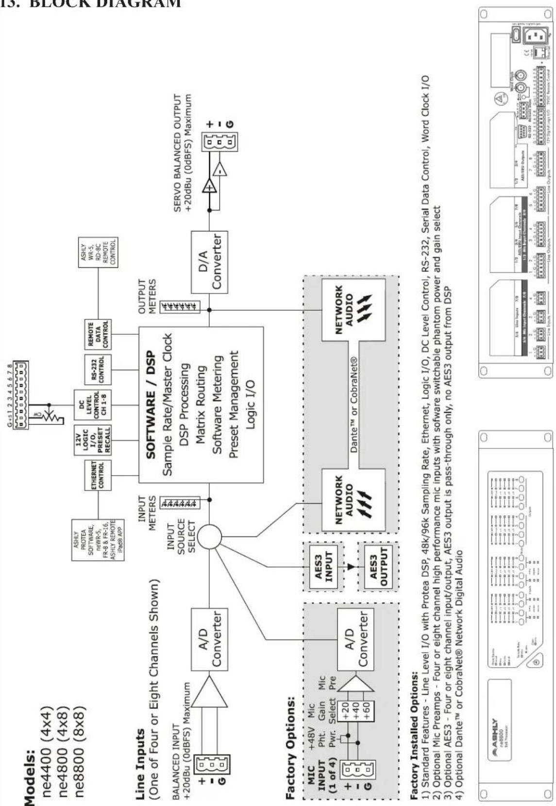
flowchart
graph TD
    subgraph "Line Inputs (One of Four or Eight Channels Shown)"
        direction TB
        A["+ G"] --> B["A/D Converter"]
        B --> C(( ))
        C --> D["INPUT SOURCE SELECT"]
        D --> E["SOFTWARE / DSP Sample Rate/Master Clock DSP Processing Matrix Routing Software Metering Preset Management Logic I/O"]
        F["BALANCED INPUT +20dBu (0dBFS) Maximum"] --> B
        G["ESHLY PROTEA SOFTWARE, neWR-5, FR-8 & FR-16, ASHLY REMOTE iPad8 APP"] --> H["ETHERNET CONTROL"]
        I["12V LOGIC I/O, PRESET RECALL"] --> H
        J["DC LEVEL CONTROL CH 1-8"] --> H
        K["RS-232 CONTROL"] --> H
        L["REMOTE DATA CONTROL"] --> H
        M["ASHLY WR-5, RD-BC REMOTE CONTROL"] --> H
        N["OUTPUT METERS"] --> O["D/A Converter"]
        P["SERVO BALANCED OUTPUT +20dBu (0dBFS) Maximum"] --> Q["+ G"]
    end

    subgraph "Factory Options"
        R["MIC INPUT (1 of 4)"] --> S["A/D Converter"]
        T["+48V Pht. Gain Mic Pwr. Select Pre"] --> S
        U["AES3 INPUT"] --> V["AES3 OUTPUT"]
        W["NETWORK AUDIO"] --> X["Dante™ or CobraNet®"]
        Y["NETWORK AUDIO"] --> Z["Network Audio"]
    end

    subgraph "Factory Installed Options"
        AA["ASHLY ne8800 Cell Processor"] --> AB["Switch Rate: 7/8, 6/9, 7/10, 7/11, 7/12, 7/13, 7/14, 7/15, 7/16, 7/17, 7/18, 7/19, 7/20, 7/21, 7/22, 7/23, 7/24, 7/25, 7/26, 7/27, 7/28"] --> AB
    end

    style A fill:#f9f,stroke:#333
    style B fill:#ccf,stroke:#333
    style C fill:#cfc,stroke:#333
    style D fill:#fcc,stroke:#333
    style E fill:#ffc,stroke:#333
    style F fill:#fcc,stroke:#333
    style G fill:#fcc,stroke:#333
    style H fill:#fcc,stroke:#333
    style I fill:#fcc,stroke:#333
    style J fill:#fcc,stroke:#333
    style K fill:#fcc,stroke:#333
    style L fill:#fcc,stroke:#333
    style M fill:#fcc,stroke:#333
    style N fill:#fcc,stroke:#333
    style O fill:#fcc,stroke:#333
    style Q fill:#fcc,stroke:#333
    style R fill:#fcc,stroke:#333
    style S fill:#fcc,stroke:#333
    style T fill:#fcc,stroke:#333
    style U fill:#fcc,stroke:#333
    style V fill:#fcc,stroke:#333
    style W fill:#fcc,stroke:#333
    style X fill:#fcc,stroke:#333
    style Y fill:#fcc,stroke:#333
© 2014 All features, specifications, and graphical representations are subject to change or improvement without notice. R0614
14. Optional Input/Output Modules
(Factory Installed)
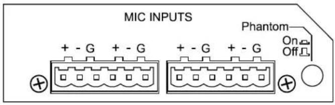
Four Channel Mic Input with Phantom Power
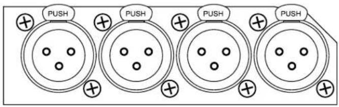
Eight or Four Channel AES3 Input (four or two stereo digital inputs)
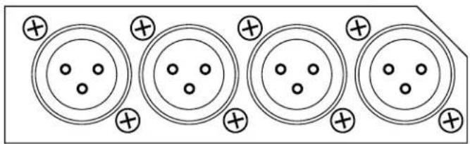
natural_image
Pure electrical circuit lines without any symbolsEight or Four Channel AES3 Output (four or two stereo digital outputs)
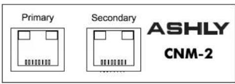
CobraNet Audio Network Input/Output
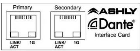
Dante Audio Network Input/Output
(See page 8 for further option details)
15. Ashly Audio Inc. LIMITED WARRANTY (USA ONLY)
(Other countries please contact your respective distributor or dealer.)
For units purchased in the USA, warranty service for this unit shall be provided by ASHLY AUDIO, INC. in accordance with the following warranty statement.
ASHLY AUDIO, INC. warrants to the owner of this product that it will be free from defects in workmanship and materials for a period of FIVE years from the original-date-of-purchase. ASHLY AUDIO INC. will without charge, repair or replace at its discretion, any defective product or component parts upon prepaid delivery of the product to the ASHLY AUDIO, INC. factory service department, accompanied with a proof of original-date-of-purchase in the form of a valid sales receipt. This warranty gives you specific legal rights, and you may also have other rights, which vary from state to state.
EXCLUSIONS: This warranty does not apply in the event of misuse, neglect, or as a result of unauthorized alterations or repairs made to the product. This warranty is void if the serial number is altered, defaced, or removed. ASHLY AUDIO, INC. reserves the right to make changes in design, or make additions to, or improvements upon, this product without any obligation to install the same on products previously manufactured.
Any implied warranties, which may arise under the operation of state law, shall be effective only for FIVE years from the original-date-of-purchase of the product. ASHLY AUDIO, INC. shall be obligated to only correct defects in the product itself. ASHLY AUDIO, INC. is not liable for any damage or injury, which may result from, or be incidental to, or a consequence of, such defects. Some states do not allow limitations on how long an implied warranty lasts, or the exclusion, or limitation of incidental or consequential damages, so the above limitations or exclusions may not apply to you.
OBTAINING WARRANTY SERVICE:
For warranty service in the United States, please follow this procedure:
1) Return the product to ASHLY AUDIO, INC. freight prepaid, with a written statement describing the defect and application that the product is used in. ASHLY AUDIO, INC. will examine the product and perform any necessary service, including replacement of defective parts, at no further cost to you.
2) Ship your product to:
ASHLY AUDIO, INC.
Attention: Service Department
847 Holt Road
Webster, NY 14580-9103
- Network Enabled DSP Processor
- Table Of Contents
- INTRODUCTION
- About Ashly
- UNPACKING
- THE NE PROCESSOR SERIES
- Base Models:
- AC POWER AND MECHANICAL REQUIREMENTS
- GETTING STARTED
- Download the software
- Connect to Ethernet
- Identify the processor in software
- The NE system project canvas
- FRONT PANEL FEATURES
- ⑦ STANDARD BACK PANEL FEATURES
- OPTIONAL BACK PANEL FEATURES
- PROTEA ne SOFTWARE
- Device Options Menu
- Flash Reprogram
- Link Configuration
- Meter Display
- AES3 Receiver Status
- Sample Rate and Master Clock Selection
- Disable Front Panel Mutes
- DVCA Control
- DSP Enable/Disable Control
- Network Audio Matrix
- Preset Options
- Presets and Sub Presets
- The NE Processor Control Surface
- Input Source
- DSP Controls
- Metering
- Logic I/O
- Security
- Network Properties
- REMOTE CONTROL (check the Ashly website for updated or additional remote control models)
- WR-5 Programmable Zone Controller
- (10.1 WR-5 continued)
- RD-8C or RW-8C Remote Fader Control
- WR-1 Remote DC Level Control
- WR-1.5 Level and Preset Recall (not shown)
- WR-2 Pushbutton Preset Recall (not shown)
- FR-8 and FR-16 Networked Fader Controller
- neWR-5 Networked Programmable Button Controller
- Ashly Remote App for iPad®
- DSP Specifications
- Dynamics
- Brick Wall Limiter
- Compressor
- Autoleveler
- Ambient Noise Compensator (outputs only)
- Ducker
- Gate
- Gain
- Equalization
- Feedback Suppressor (inputs only, 48kHz only)
- FIR Filter (output only, 48kHz only, 2-384 taps)
- Graphic EQ
- Parametric EQ
- Parametric Filters
- 6/12dB Hi/Low Shelf Filters
- All Pass Filter
- Variable Q HP/LP Filters
- Notch Filter
- Bandpass Filter
- Crossover
- Way, 3 Way, 2 Way on Outputs Only,
- Low-Pass and High Pass Filters on Inputs and Outputs
- Delay
- Speaker Delay
- Long Delay
- Tools
- Signal Generator
- Individual Channel Level Meters
- Matrix Mixer
- Linking
- TROUBLESHOOTING TIPS
- No Ethernet Communications
- No Audio Meter Activity
- No Audio Output
- Distorted Sound
- WR-5 Doesn't Work
- RD-8C or RW-8C Doesn't Work
- WR-1 Doesn't Work
- How Do I Use RS-232?
- Optional Input/Output Modules
- Ashly Audio Inc. LIMITED WARRANTY (USA ONLY)
- OBTAINING WARRANTY SERVICE:
Brand : Ashly
Model : ne8800
Category : Audio processor