FR-16 - Processor Ashly - Free user manual and instructions
Find the device manual for free FR-16 Ashly in PDF.


| Product Type | Digital Signal Processor |
| Brand | Ashly |
| Model | FR-16 |
| Number of Channels | 16 |
| Power Supply | 100-240V AC, 50/60Hz |
| Dimensions | 19" x 1.75" x 8.5" (rack mount, 1U) |
| Weight | 5.5 lbs (2.5 kg) |
| Sample Rate | 96 kHz |
| Bit Depth | 24-bit |
| Input Connectors | 16 x XLR balanced |
| Output Connectors | 16 x XLR balanced |
| Control Interface | Ethernet, USB, RS-232 |
| DSP Functions | EQ, Crossover, Dynamics, Delay, Matrix Mixing |
| Presets | 64 user presets |
| Operating Temperature | 0°C to 40°C |
| Storage Temperature | -20°C to 70°C |
| Humidity | 10% to 90% non-condensing |
| Safety Compliance | CE, UL, RoHS |
| Maintenance | Clean with dry cloth; do not use liquids |
| Spare Parts | Contact Ashly support for replacement parts |
| Repairability | Serviceable by qualified technician; refer to manual |
Frequently Asked Questions - FR-16 Ashly
User questions about FR-16 Ashly
0 question about this device. Answer the ones you know or ask your own.
Ask a new question about this device
Download the instructions for your Processor in PDF format for free! Find your manual FR-16 - Ashly and take your electronic device back in hand. On this page are published all the documents necessary for the use of your device. FR-16 by Ashly.
USER MANUAL FR-16 Ashly
FR-8 and FR-16 Programmable Fader Control

natural_image
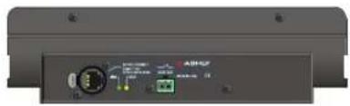
Back panel of a network device showing ports, connectors, and a central connector (no visible text or symbols)Overview
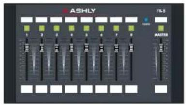
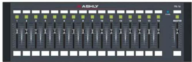
The FR-8 and FR-16 are Ethernet-based programmable fader remote controllers for all Ashly networked products with DSP capabilities. Each fader and it's push button LED can be programmed to adjust signal level, select input source, or mute the signal. The FR remotes are ideal for networked sound systems in meeting rooms, houses of worship, courtrooms, or other applications where simple but programmable real-time level control is required.
Features
• 8 or 16 Assignable Faders with Master
- Push Button Switches with LED
- Mute/Unmute per Fader
• A/B Source Select per Fader (programmable)
- Two Signal Level Indicators per Fader
- User Defined Signal Level LED Thresholds
- Assignable Fader Scaling
- Front Panel Lockout
- Communication Failure Indicator
• Automatic IP Addressing - User Defined Label Inserts
• Wall Box, Rack, or Panel Cut-Out Mounting
Requirements
- Ethernet Network
• Class 1 IEEE 802.3af Power Over Ethernet -
Ashly Networkable Device with DSP
-
PC Running Microsoft® Windows XP or higher, 32 & 64 bit
- Protea ^ne Software v5.11 or Higher
Compatible Ashly Devices
- nc24.24M
• NE Two-Channel Amplifiers (with DSP)
• NE Multi-Channel Amplifiers (with DSP)
• NE4400, 4800, and 8800 DSP Processors
- Pema Amplifiers
- nXp Amplifiers
☐ FR Features (FR-8 not shown)
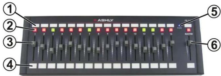
Front Panel
1) Push Button LED Label Window - Insert label made from Ashly template doc (page 12)
2) Push Button LED - Used to switch fader Mute or fader A/B Source Select. LED also indicates signal level or fader status
3) Channel Fader - Adjusts level of targeted DSP gain stage or output mixer source
4) Channel Fader Label Window - Insert label made from Ashly template doc (page 12)
5) Power LED - Shows device is powered
6) Master Fader - Adjusts level of all assigned channel faders
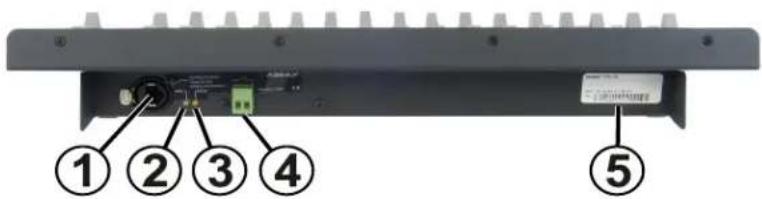
Rear Panel
1) RJ-45 Jack - Connects to Ethernet Network with PoE or PoE injector
2) Link LED - Shows network is connected
3) Data LED - Shows Data is transferring
4) Lockout Connector - Use with any switch to disable all front panel controls when closed
5) Serial Number and MAC Address - Used for warranty or flash programming
On Startup:
- When the FR-8 or FR-16 is first connected or powered on, it attempts to communicate with all devices it has been programmed to control, if any.
- Once communication with the targeted device is established, it waits to transmit any fader or switch position data until a control is physically changed by the user. At that point only the data for that control is sent. This feature prevents sudden and unexpected changes when reconnecting or restarting the FR remote control, as well as when a new preset is recalled to the host device.
PLEASE NOTE: When in doubt, make sure all faders are either in the correct position or fully down before reconnecting
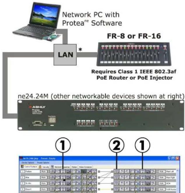
□ Typical Application
Protea ne24.24M Software Control Surface
① I/O Level Mode - Gain Control: In I/O Level mode, a fader gets assigned to one input or output DSP gain control. It's push button mutes the signal and turns red when pressed. Signal level is displayed when it is unmuted. Note that in the ne24.24M only, gain controls are in fixed locations.
② Mixer Mode - Sub-Channel Input Level: In Mixer Mode, a fader can be programmed to adjust the level of one input source routed to one output mixer. It's push button mutes the signal and turns red when pressed. Signal level is displayed when it is unmuted. The mixer is the first item in the output section.
② Mixer Mode - A/B Source Select: In A/B source select mode, the push button is programmed to toggle between two assigned input sources. The desired inputs must first be routed to the output mixer. The fader associated with the push button adjusts the level of the selected input. The LED indicates solid red or green depending on which input source is currently selected. In A/B source select mode, the mute function for that push button is disabled, as is the green signal LED function.
natural_image
Front view of a black audio amplifier unit with visible dB and control knobs (no readable text or symbols)natural_image
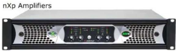
Front view of an industrial amplifier front panel with ventilation grilles and control buttons (no visible text or labels)ne4125, ne4250, ne8125, ne8250 Amplifier w DSP

ne4400, ne4800, ne8800 DSP Processor

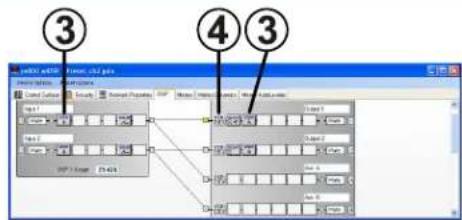
ne800 (with DSP) Protea Control Surface
③Gain in Other Networked Products: In all other networked products, the gain control must first be placed in the input or output signal chain, but otherwise functions the same as in the ne24.24M.
④ Mixer in other Networked products:
Mixer mode sub-channel input level control, as well as mixer mode source select, is the same as in the ne24.24M.
□ Connecting to a Network
Network communication is made by wiring with standard Cat-5 Ethernet cable terminated with a RJ-45 or Neutrik etherCON connector through a network router, switch, hub, or patch panel to a PC running Protea NE Software v5.10 or higher. Maximum cable distance is 100 meters (328 ft) from the nearest router, hub, or switch.
Ashly networked devices will auto detect their Ethernet network connection, and adapt (Auto-MDIX) to either a straight through pin to pin, or crossover Ethernet cable. Note that the push release tab on the back panel connector (as shown) is meant only for etherCON connectors. Standard RJ-45 connectors have their own built-in release tab.
Power Over Ethernet - FR remote controllers require Class 1 IEEE 802.3af Power over Ethernet (PoE) from a switch, hub, or in-line PoE injector. FR power consumption is a maximum of two watts.
Link/Data LEDs - Once a successful Ethernet connection has been made, the green “Link” LED will light. If the green LED is not lit, then there is either a problem with the connection or with the network. This must be addressed before proceeding further, by backtracking through cables or hardware to find the problem. The yellow “Data” LED flashes when data is sent or received from the FR device.
IP Address - There is no need to assign an IP address to FR-8/16 used with a network router. The router or Link Local Addressing will assign IP addresses to each product automatically. When a router is not available, most current NE products and remotes have the capability to assign their own IP address based on Link Local Addressing. This allows the device to operate without the need to set up static IP address. If the only option is to use an Ethernet switch instead of a router, and communications problems remain which cannot be solved with the use of the Link Local standard, each device must have a static IP address assigned from within Protea NE software. This is done by selecting “Manual Configuration” in the Network Properties tab of each FR device, where the system/network administrator must assign each product its own unique static IP address, each with the appropriate sub-net if applicable.
Firewalls - If Protea ^nc software does not detect the FR-8/16 or show real time changes, the firewall in the controlling PC may need to have Protea ^nc software added to its firewall exceptions, since firewalls may block the FR-8/16 response to the PC. The current PC firewall status is found by clicking on the Windows Start button, then Control Panel, then double clicking on the security shield where firewall exceptions are configured
Wi-Fi and LAN – For the initial device auto-configuration process, any secondary Wi-Fi connection should also be disabled, and the LAN (Local Area Network) connection must be enabled on the PC. Secondary network connections may confuse the auto device discovery process. Go to the Windows Control Panel, then Network Connections, to disable any secondary network connections. Once communications with the device is established, secondary network connections can be enabled again, unless a communications problem remains with the FR-8/16, in which case the secondary network connections should remain disabled.
Communication Failure Indicator - If an assigned fader has lost contact with its targeted device, the LED button above that fader will continually flash red to indicate communication has been lost.
□ Mechanical Installation
The FR-8 and FR-16 are designed to be mounted to an electrical wall box or modular box array, to any flat surface using the provided cutout, to a custom Ashly rack mounting kit (sold separately), or as a freestanding desktop controller.
The FR-16 will mount to a modular 7-gang US electrical box, with a minimum box depth of 2.25". The FR-8 mounts to a 4-gang electrical box. For mounting to a wall or flat surface without using a wall box, a mechanical drawing and cutout pattern are provided in this manual on pages 9.
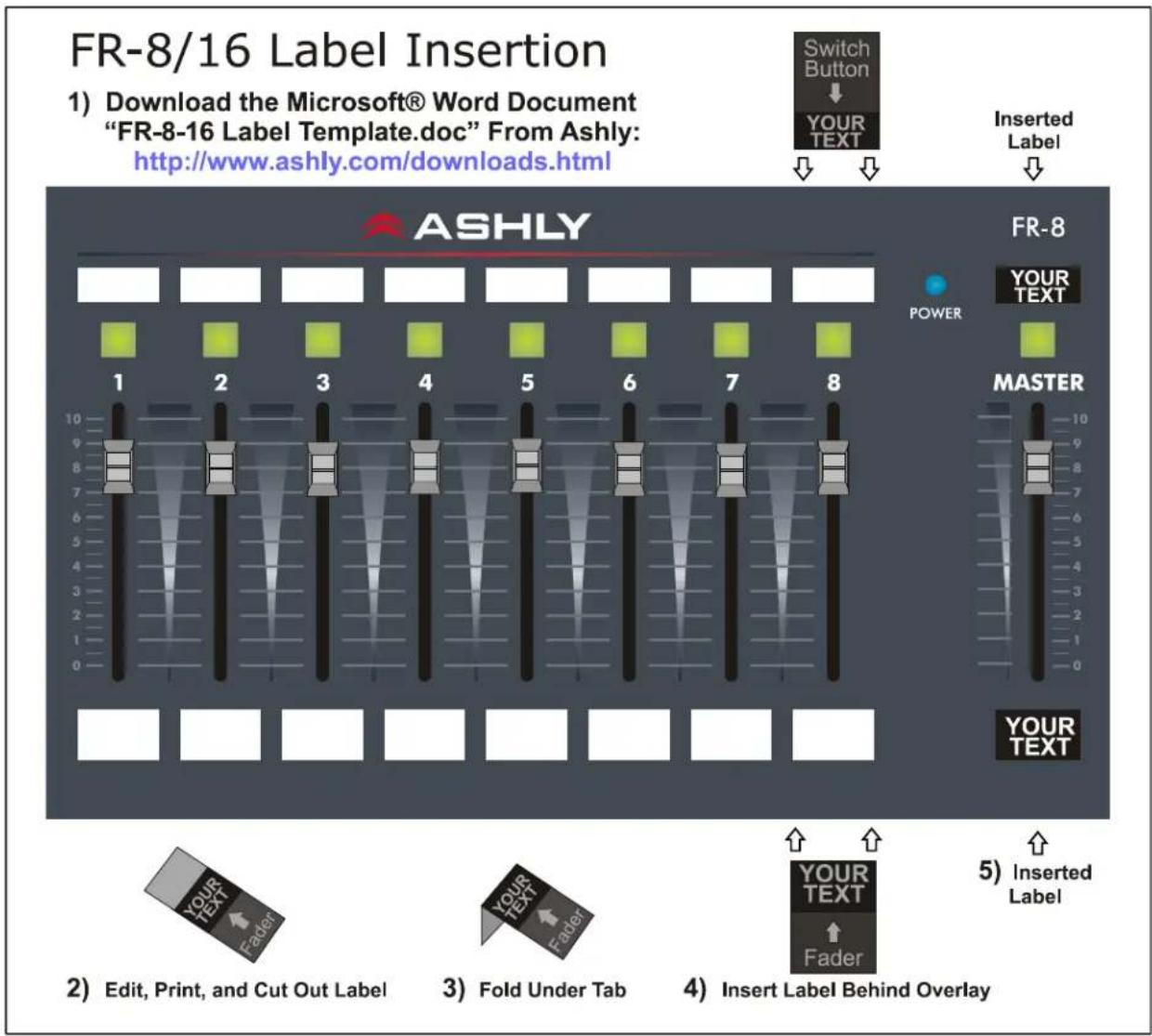
Fader and switch function labels can be created using the document template found on the Ashly website and referenced in this manual on page 10.
Follow these instructions for mounting to an electrical wall box, rack kit, or surface:
Note: Remove power before mounting. Avoid static shock disruptions to this or other connected devices by mounting to an earth-grounded metal wall box or other earth grounded point. This prevents static discharge from flowing through the data lines.
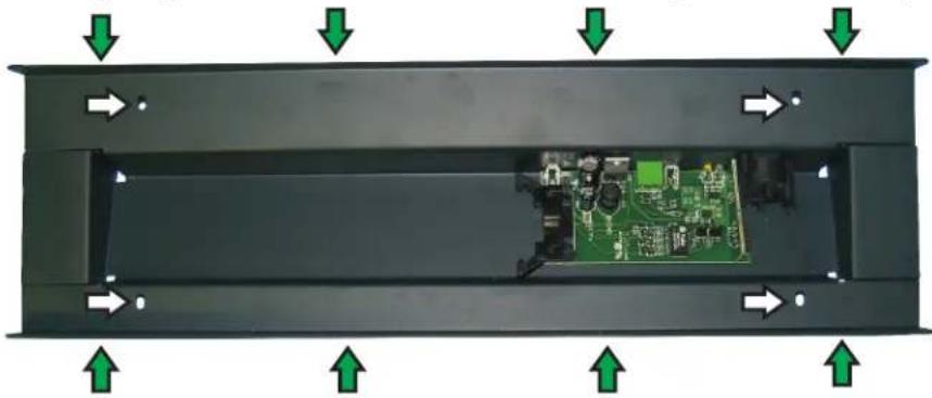
1) Remove Front Panel Using These Eight (four on FR-8) Screws.
2) Insert Fader and Switch Labels Beneath Front Panel Overlay.
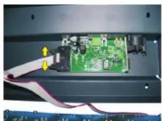
3) Remove Ribbon Cable as Shown Below.
4) Prepare Electrical Box, Panel Cutout, or Rack Mounting Kit, and Install Wiring.
5) Plug In Ethernet Cable and Lockout Wiring Before Mounting.
natural_image
Interior view of a device casing with green arrows indicating directional flow or movement, showing internal circuit board and components (no text or symbols)6) Fasten the FR Rear Panel to Wall, Wall Box, Rack Mounting Kit, or Other Flat surface Using These Four Holes.
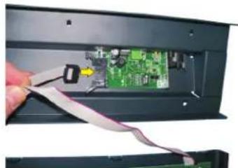
7) Re-Insert Ribbon Cable As Shown Below and Replace Front Panel.
natural_image
Interior view of an electronic device showing a green circuit board with attached wires and connectors (no visible text or symbols)(3) Remove ribbon cable by pushing apart the two cable ejector levers. Do NOT pull on ribbon cable!
natural_image
Close-up of a hand inserting a flexible cable into an electronic device panel (no visible text or symbols)(7) Re-Insert ribbon cable by pushing in the cable header back into socket. Ejector pins will automatically snap back to locked position.
□ Using Prote Software
Protea NE Software version 5.10 or greater is required for the FR Remotes. Load it from the supplied CD or Ashly website to a PC running Microsoft® Windows 7/Vista/XP, 32 & 64 bit.
Network Tree - Start Protea NE Software and the FR-8/16 should appear in the network tree in the “Ashly Remotes” folder. From the factory, it should appear with the name “FR-8 (or 16) Fader Remote” in green. If it doesn’t appear, click the “Scan For Devices” button under the network tree. All devices continuously broadcast their availability to the software. All currently connected and active products are highlighted in green, while products which have been formerly connected but are currently off-line or unavailable show up in red. To clear the network tree of all unavailable (red) items, right click the top level item (Ashly Network) and select
Project Canvas - To configure the FR-8/16, double-click its icon in the network tree. This will bring up the FR-8/16's control surface. Alternatively, you can drag the icon from the network tree onto the project canvas where it will then appear as a shortcut. You can then double-click on this shortcut to bring up its control surface.
Drawing elements such as lines, rectangles, text, and image files can be added to the canvas to complete a visual control screen displaying all Ashly devices under control, which is then saved as a project file. Drawing elements are found as icons above the canvas. To add text or image files, right click over empty canvas. The saved project file contains all devices, settings, and drawing elements shown on the project canvas.
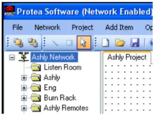
Note: Once an image has been placed on the canvas, it must be manually deleted if that device is no longer available to the software. Also note that scanning for devices does not automatically remove images which may have been previously installed but are now off-line. To clear the canvas of all devices and drawn elements, click
Design Mode - Design Mode must be enabled to work with devices or drawing elements in the project canvas. Right-click on canvas to enable Design Mode. This allows placed objects to be moved around, while unchecking Design Mode locks objects in place and prevents the addition of other objects or devices. Further help is available in Protea NE software by navigating through the online help menu.
□ Main Control Surface
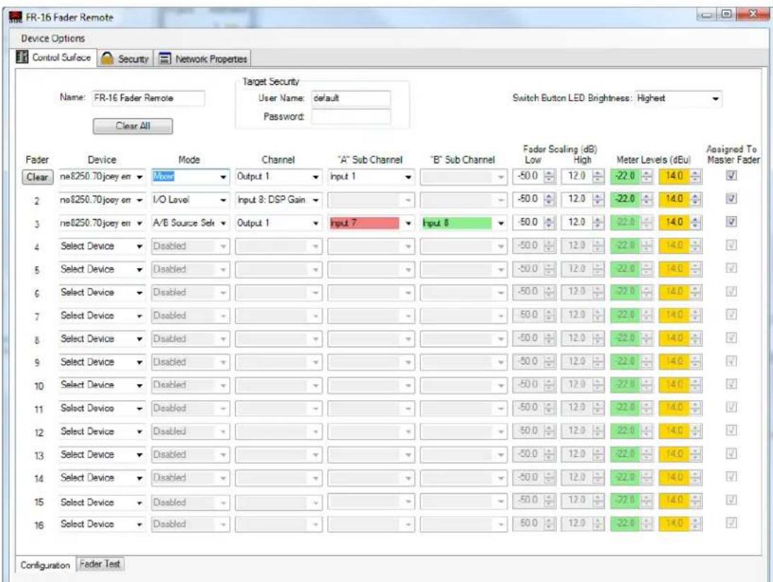
Within the main FR-8 or FR-16 control surface, there are two tabs at the bottom labeled “Configuration” and “Fader Test”. All device targeting and programming of faders is done in the configuration tab. The fader test tab (not shown) is used for visual reference only by indicating current FR fader and switch position as well as front panel lockout status. The main configuration window is shown on the following page,
Global Features
Device Name: Up to 20 characters can be used for the device name. The name appears in the network tree in the Protea ^ne Software startup screen, as well as the main FR device screen.
Target Security: When target security is left unspecified or in its default state (user name = “default” with no password), the FR remote will have full access to all available control parameters on the targeted DSP device. However, if an administrator wishes to limit control parameter access from a FR controller to a selected target device, they must enter the same user name and password on both the FR-8/16 target security fields and on the specified target’s device users section, under the general security tab. Think of it as creating a login requirement for each device before they can be assigned to work together, up to the level of parameter access granted by the target device. Note that even though “Default” and “Admin” are reserved system user names, any changes to these reserved FR name or password fields requires a corresponding entry on the target device. Also note that target security is completely independent from the general FR security section described on page 9, and that user names and passwords implemented there have no impact to or from those used for target security.
LED Brightness: The overall brightness of FR-8 and FR-16 LEDs can be adjusted to one of four levels to match ambient room lighting. The factory default is for the brightest setting.
Clear All: This button clears the control parameters of all faders in the configuration window and returns them to factory default settings. It also clears the FR device target security user name and password. Note: individual fader parameters can be cleared by clicking on any control for that fader and then clicking the pop-up “Clear Fader” button associated with that fader.
Fader Specific Features
Individual fader control parameters include assignment of the target device, fader mode, device channel, A/B mixer sub-channel source selection, fader scaling, signal level LED transition points, and assignment to master fader. An individual fader “Clear Function” button appears when editing any control point in a fader row, and returns that fader back to it’s default settings.
Fader: The total number of faders available on the FR remote are shown here, either 8 or 16.
Device: Each fader can target one device from the drop down device list, or be left inactive.
Mode: Once a target DSP device has been selected, a fader can operate in one of three modes, Mixer Mode, I/O Level Control Mode, or A/B Source Select Mode.
1) Mixer Mode - In mixer mode, a fader is first assigned to a target device's output channel mixer, then assigned one of that mixer's available input channels, also called the Sub channel. The fader action controls the sub channel's signal level applied to that output mixer.
2) I/O Level Control Mode - In I/O level control mode, a fader controls a single dedicated input or output gain control in the DSP section, but not in the mixer section. For controlling a stereo signal, link input or output gain functions together using the software control surface of the target DSP device.
3) A/B Source Select - In A/B source select mode, a push button toggles between two different inputs assigned to one output mixer. The inputs must first be routed to the output mixer of the DSP device under control, then two available input sources for A/B selection are assigned. The fader adjusts the level of the currently toggled input to that mixer.
LED function in mixer or I/O level mode: In this mode, push button LEDs indicate signal level by flashing green and amber, and indicate mute with solid red. LED signal level thresholds have default settings of -22dBu for green and +14dBu for amber, and can be changed by the user. Note that a LED assigned to an input gain control or mixer input source indicates pre-fader signal level, while one associated with an output gain stage is post-fader.
LED function in A/B source select mode: In this mode, the LED will either be solid red for source “A”, or solid green for source “B”. In A/B source select mode, the green signal level function is disabled, as is the mute function. The amber signal level LED still operates normally.
LED Level Transition Points - Signal level LEDs have two thresholds, first where the green signal LED turns on, then when it transitions from green to amber. Both points can be defined by the user for each fader. Factory default transition points are -22dBu for green and +14dBu for amber. Note that the green signal level LED is disabled in A/B source select mode, but not amber.
Fader Scaling - The gain range for target DSP gain stages is -50dB to +12dB. By default, the fader will use the full range of the DSP gain function under its control. Using fader scaling, an upper and/or lower dB limit can be set to avoid insufficient or excessive audio level.
Master Fader Assignment - Faders can be individually selected or unselected for control by the master fader. The factory default is for all faders to be assigned to the master fader. If a fader appears to be functioning but has no effect on level, check that the master fader is not muted or turned down.
Other Features
Front Panel Lock-Out
When unintended or unauthorized control changes need to be prevented, a keyed switch or contact closure can be connected to the lockout connector. When the two lockout pins are unconnected, the front panel operates normally. When the lockout pins are connected closed, physical changes on the front panel are locked out and ignored by software. Note: Before unlocking the front panel, it is suggested that all faders first be placed fully down or at pre-determined marked levels to avoid excess volume. Lock-out status is indicated in software in the main control surface fader test tab window.
Factory Reset
To restore the unit to it's default settings and erase all stored parameters, follow these steps:
1) Remove power from the FR-8/16.
2) Press and hold down buttons 1, 2, 3, 4 on the FR-8, or buttons 9, 10, 11, 12 on the FR-16.
3) Apply power, holding the buttons down for a count of four as indicated by the lighting of four red LEDs. To cancel the reset, release all buttons before the count to four is complete.
4) A successful reset is indicated when all LEDs glow amber, then the buttons can be released.
Security
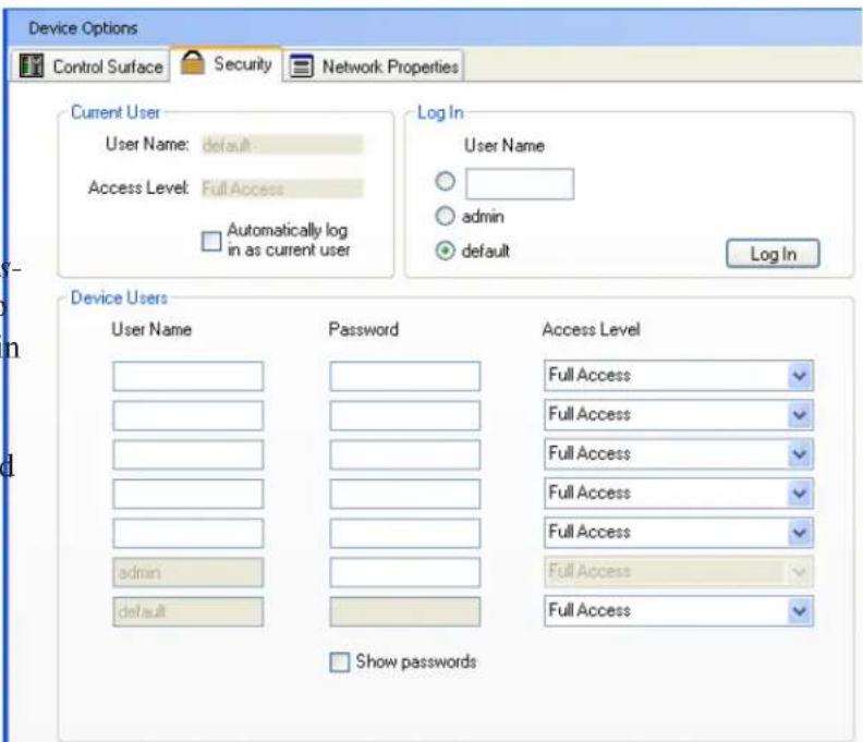
In addition to the hardware lockout, there are multiple user/multiple levels of FR-8 and FR-16 security assignable within the security tab. The security data is stored within the FR remote device itself, not Protea NE Software. Passwords are case sensitive. Be sure to write down the password and store in a convenient place for future reference. Note that device security is different than the target security, and is located next to the main control surface configuration window tab.
Firmware Update (Flash Reprogram)
To view the current FR firmware revision, click on
the control surface Network Properties tab and look under Hardware Configuration. If a newer firmware update is available on the Ashly website, download it and run the Flash Reprogram procedure found in the FR Device Options menu. If the control surface is somehow unable to communicate with the FR device due to a corrupt internal program, run flash reprogram from the main Protea ^nc window under Flash Programmer/Launch Flash Reprogram. This requires the FR device MAC address, found on the FR back panel (see procedure in the troubleshooting section). When the FR device is put into flash reprogram mode, the highest channel LED turns green and the Master LED turns amber. All control function is suspended until re-programming is completed
Using Multiple Remote Controllers
Protea ^ne software allows multiple NE remote controllers the ability to target the same DSP device. For example, an Ashly neWR-5 could target the same DSP device as an FR-16, if the user wanted to add remote preset or logic control in addition to FR remote gain control. Note that in this case, both the FR remote and the neWR-5 could conceivably target the same gain control on the target DSP device, however Ashly does not recommend this practice. If it is deemed necessary to have two remote control devices controlling the same function, the last remote device action will always take effect, regardless of which device it is and regardless of the position or settings of the other remote device(s). This is true for any combination of Ashly NE remote control devices targeting the same device and function. The administrator can avoid the possibility of redundant control situations like this by using the target security feature. (see page 7).
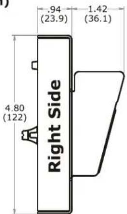
Dimensions
Inches (mm)
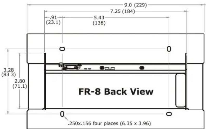
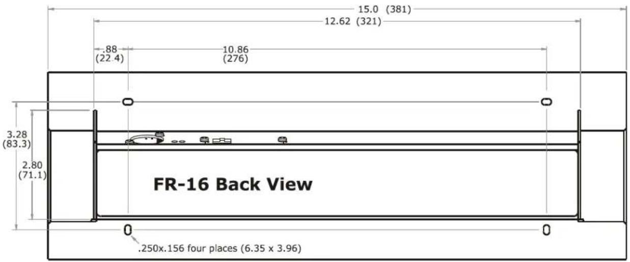
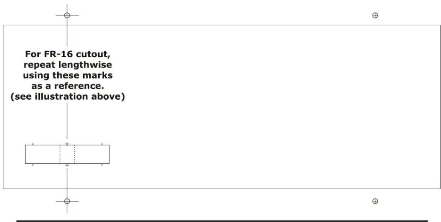
Panel Mount Cutout Pattern
Note: This template is also available as a pdf download from the Ashly website. Look in the downloads section, then under FR-8 and FR-16 Application Notes.
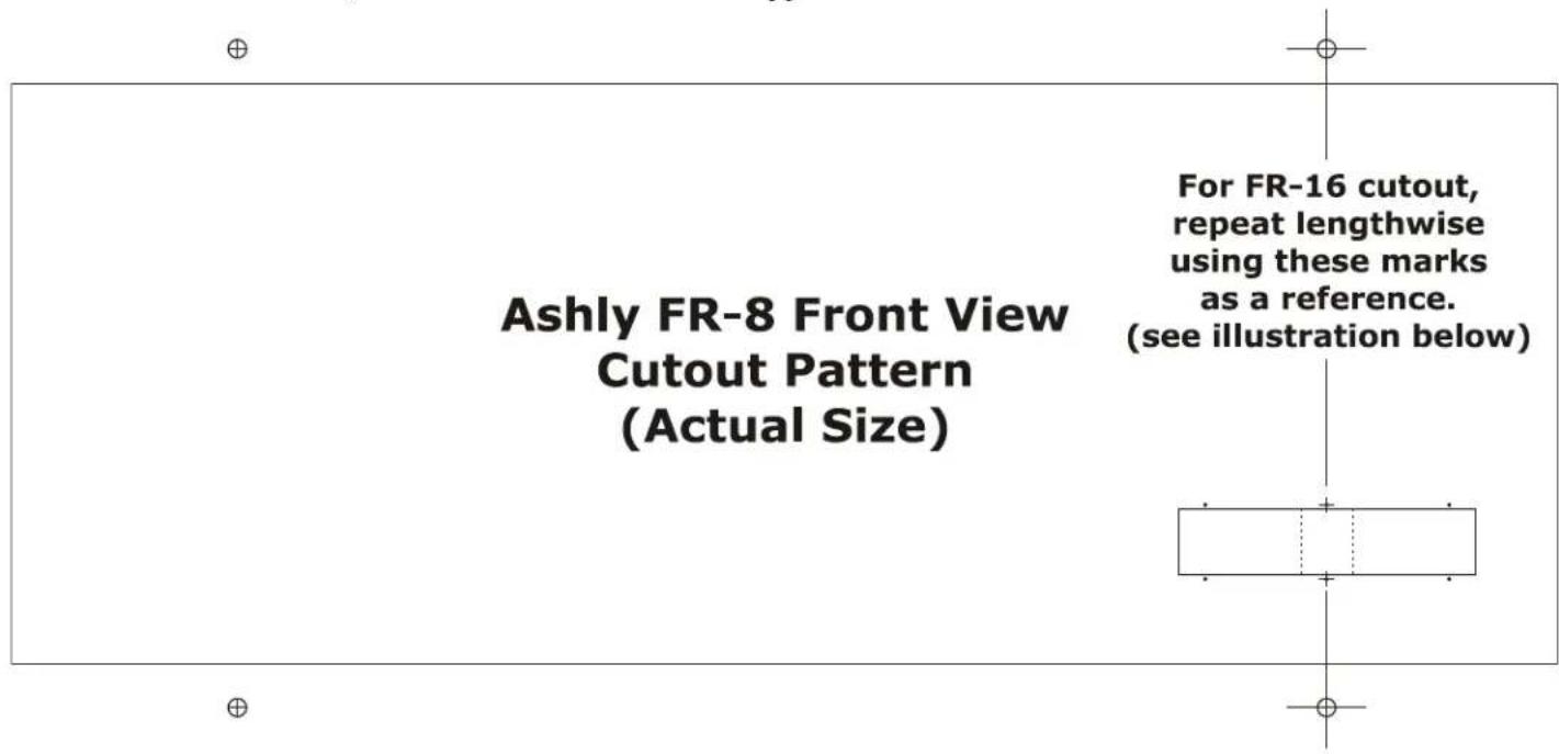
This line is exactly 7.000 inches long. Before using this drawing as a cutout template, confirm its dimensional accuracy with a ruler, and make any necessary scaling adjustments to your printer settings.
☐ Function Label Template
An editable document template is available on the Ashly website for making custom labels. Text, text color, and background color can be individually defined for each label and inserted behind the front panel overlay windows as shown below.
Note: The front panel must be removed for label insertion. See instructions on page 5.
Troubleshooting Tips:
1) I can't find the target device I want to control - Is the target device plugged into the network? Is it turned on? Are there multiple target devices of the same model? Rename individual devices with a unique identifier. For an immediate update of available devices, click
2) How do I get rid of extra target devices listed that do not exist? The FR target device drop down listing is taken directly from the main Proteane network tree. Devices listed in the network tree appear green if they are live units, and red if they were once available but are now offline. To clear all inactive devices from the menu tree, right click on
3) Even though my user name is "default" or "admin", I don't have access to the target device - Are there any additional text characters in the user name field? Is the password field blank? Any password entry, even on the reserved user-names of "default" or "admin" must have a corresponding match in the target devices.
4) What do the various LED indicators and blinking patterns mean?
Mute/Unmute - If a fader is assigned to either I/O level mode or mixer mode, it's push button will be solid red when muted. Mute function is disabled in A/B source select mode. If a fader is unassigned, it will not light.
Signal Level - LEDs indicate signal level with green and amber according to the defined dBu thresholds. If the fader is not assigned a function, it remains dark. The green signal level LED is disabled in A/B source select mode.
A/B Source Select - In this mode the LED will be either solid red or green to indicate which input source is selected. The amber signal level LED remains active and mute is disabled.
Factory Reset - All LEDs glow amber during factory reset until held buttons are released.
Communications failure - If a fader was assigned to a target device, but that target device becomes unavailable, the fader LED will continuously flash red to indicate that communication has been lost for that fader. See if the target device is powered on and connected properly to the network.
Flash Reprogram - In flash reprogram mode, all controls are disabled and the highest fader LED glows solid green while the master fader LED glows amber. Once reprogramming begins, red LEDs blink to indicate the new program is being loaded. Upon completion, all LEDs either turn off or revert to their previously defined status, and the FR device is ready for use. Unlike factory reset, flash reprogram does not delete or overwrite user settings on the FR device.
5) Why won't the FR device let me flash reprogram it? If the firmware program in the FR device becomes corrupt for some unexpected reason, you will not be able to flash reprogram it from the FR control surface in Protea ^ne software. Rather, you must use the main Protea ^ne flash reprogrammer as follows:
1) Click on
2) Click
3) In the Select Device window, click
4) Select the latest FR firmware file from the Ashly website or CD
5) Enter MAC address found on FR device back panel
6) Enter IP address of 255.255.255.255
7) Finally, click
Ashly Audio Inc. LIMITED WARRANTY (USA ONLY)
(Other countries please contact your respective distributor or dealer)
For units purchased in the USA, warranty service for this unit shall be provided by ASHLY AUDIO, INC. in accordance with the following warranty statement.
ASHLY AUDIO, INC. warrants to the owner of this product that it will be free from defects in workmanship and materials for a period of FIVE years from the original-date-of-purchase. ASHLY AUDIO INC. will without charge, repair or replace at its discretion, any defective product or component parts upon prepaid delivery of the product to the ASHLY AUDIO, INC. factory service department, accompanied with a proof of original-date-of-purchase in the form of a valid sales receipt. This warranty gives you specific legal rights, and you may also have other rights, which vary from state to state.
EXCLUSIONS: This warranty does not apply in the event of misuse, neglect, or as a result of unauthorized alterations or repairs made to the product. This warranty is void if the serial number is altered, defaced, or removed. ASHLY AUDIO, INC. reserves the right to make changes in design, or make additions to, or improvements upon, this product without any obligation to install the same on products previously manufactured.
Any implied warranties, which may arise under the operation of state law, shall be effective only for FIVE years from the original-date-of-purchase of the product. ASHLY AUDIO, INC. shall be obligated to only correct defects in the product itself. ASHLY AUDIO, INC. is not liable for any damage or injury, which may result from, or be incidental to, or a consequence of, such defects. Some states do not allow limitations on how long an implied warranty lasts, or the exclusion, or limitation of incidental or consequential damages, so the above limitations or exclusions may not apply to you.
OBTAINING WARRANTY SERVICE:
For warranty service in the United States, please follow this procedure:
1) Return the product to ASHLY AUDIO, INC. freight prepaid, with a written statement describing the defect and application that the product is used in. ASHLY AUDIO, INC. will examine the product and perform any necessary service, including replacement of defective parts, at no further cost to you.
2) Ship your product to:
ASHLY AUDIO, INC.
Attention: Service Department
847 Holt Road
Webster, NY 14580-9103
FCC Compliance
This equipment has been tested and found to comply with the limits for a Class A digital device, pursuant to part 15 of the FCC Rules. Operation is subject to the following two conditions:
- This device may not cause harmful interference
- This device must accept any interference received, including interference that may cause undesired operation
Notes:
ASHLY
ASHLY AUDIO INC. 847 Holt Road Webster, NY 14580-9103, USA
Phone: (585) 872-0010 Fax: (585) 872-0739
Toll Free (800) 828-6308 www.ashly.com
©2014 by Ashly Audio Corporation. All rights reserved worldwide.
Ashly Audio is a division of Jam Industries, Ltd.
All features, specifications, and graphical representations are subject to change or improvement without notice.
- FR-8 and FR-16 Programmable Fader Control
- Overview
- Features
- Requirements
- Compatible Ashly Devices
- ☐ FR Features (FR-8 not shown)
- Front Panel
- Rear Panel
- On Startup:
- □ Typical Application
- □ Connecting to a Network
- □ Mechanical Installation
- Follow these instructions for mounting to an electrical wall box, rack kit, or surface:
- □ Using Prote Software
- □ Main Control Surface
- Global Features
- Fader Specific Features
- Other Features
- Front Panel Lock-Out
- Factory Reset
- Security
- Firmware Update (Flash Reprogram)
- Using Multiple Remote Controllers
- Dimensions
- Panel Mount Cutout Pattern
- ☐ Function Label Template
- Troubleshooting Tips:
- Ashly Audio Inc. LIMITED WARRANTY (USA ONLY)
- (Other countries please contact your respective distributor or dealer)
- OBTAINING WARRANTY SERVICE:
- For warranty service in the United States, please follow this procedure:
- FCC Compliance
- ASHLY
Brand : Ashly
Model : FR-16
Category : Processor