VigorSwitch G1282 - Switch Draytek - Free user manual and instructions
Find the device manual for free VigorSwitch G1282 Draytek in PDF.


| Product Type | Web Smart Managed Gigabit Switch |
| Ports | 24 x 10/100/1000Mbps RJ45 + 4 x Combo RJ45/SFP (ports 25-28) |
| Dimensions | Standard 19-inch rack width, 1U height |
| Weight | Approx. 2.5 kg (estimate) |
| Power Supply | AC 100~240V, 50/60Hz via internal power adapter |
| Power Consumption | Max 20W (typical, with IEEE 802.3az Energy Efficient Ethernet) |
| Management Interfaces | Web UI, Telnet, SSH, HTTP, HTTPS, SNMP, CLI |
| Default IP Address | 192.168.1.224 (DHCP client enabled by default) |
| Default Login | Username: admin, Password: admin |
| Key Features | VLAN (port-based & 802.1Q, up to 4094 IDs), QoS (8 queues, SP/WRR), Link Aggregation (LACP/Static), STP/RSTP, IGMP Snooping, ONVIF Surveillance, Voice VLAN, Port Mirroring, Jumbo Frame (up to 10000 bytes) |
| Operating Temperature | +5°C to +40°C |
| Safety | Do not open or repair yourself; keep away from damp; use indoors only; disconnect power before cleaning |
| Installation | Rack-mountable (brackets included) or desktop placement |
| Standards Compliance | IEEE 802.3, 802.3u, 802.3x, 802.3z, 802.1Q, 802.1p, 802.3ad, 802.1D, 802.1w, 802.3az |
| Firmware Upgrade | Via Web UI or TFTP |
Frequently Asked Questions - VigorSwitch G1282 Draytek
User questions about VigorSwitch G1282 Draytek
0 question about this device. Answer the ones you know or ask your own.
Ask a new question about this device
Download the instructions for your Switch in PDF format for free! Find your manual VigorSwitch G1282 - Draytek and take your electronic device back in hand. On this page are published all the documents necessary for the use of your device. VigorSwitch G1282 by Draytek.
USER MANUAL VigorSwitch G1282 Draytek
Web Smart Managed Switch


User's Guide
VigorSwitch G1282
Web Smart Managed
User's Guide
Version: 1.2
Firmware Version: V2.8.5
Date: July 26, 2023
Intellectual Property Rights (IPR) Information
Copyrights
© All rights reserved. This publication contains information that is protected by copyright. No part may be reproduced, transmitted, transcribed, stored in a retrieval system, or translated into any language without written permission from the copyright holders.
Trademarks
The following trademarks are used in this document:
• Microsoft is a registered trademark of Microsoft Corp.
Windows 8, 10, 11 and Explorer are trademarks of Microsoft Corp.
Apple and Mac OS are registered trademarks of Apple Inc.
Other products may be trademarks or registered trademarks of their respective manufacturers.
Safety Instructions and Approval
Safety Instructions
Read the installation guide thoroughly before you set up the device.
The switch is a complicated electronic unit that may be repaired only be authorized and qualified personnel. Do not try to open or repair the switch yourself.
Do not place the switch in a damp or humid place, e.g. a bathroom.
The switch should be used in a sheltered area, within a temperature range of +5 to +40 Celsius.
- Do not expose the switch to direct sunlight or other heat sources. The housing and electronic components may be damaged by direct sunlight or heat sources.
- Do not deploy the cable for LAN connection outdoor to prevent electronic shock hazards.
Do not power off the device when saving configurations or firmware upgrades. It may damage the data in a flash. Please disconnect the Internet connection on the device before powering it off when a TR-069/ ACS server manages the device.
- Keep the package out of reach of children.
- When you want to dispose of the modem, please follow local regulations on conservation of the environment.
Warranty
We warrant to the original end user (purchaser) that the switch will be free from any defects in workmanship or materials for a period of two (2) years from the date of purchase from the dealer. Please keep your purchase receipt in a safe place as it serves as proof of date of purchase. During the warranty period, and upon proof of purchase, should the product have indications of failure due to faulty workmanship and/or materials, we will, at our discretion, repair or replace the defective products or components, without charge for either parts or labor, to whatever extent we deem necessary tore-store the product to proper operating condition. Any replacement will consist of a new or re-manufactured functionally equivalent product of equal value, and will be offered solely at our discretion. This warranty will not apply if the product is modified, misused, tampered with, damaged by an act of God, or subjected to abnormal working conditions. The warranty does not cover the bundled or licensed software of other vendors. Defects which do not significantly affect the usability of the product will not be covered by the warranty. We reserve the right to revise the manual and online documentation and to make changes from time to time in the contents hereof without obligation to notify any person of such revision or changes.
Be a Registered Owner
Web registration is preferred. You can register your Vigor router via https://myvigor.draytek.com.
Firmware & Tools Updates
Due to the continuous evolution of DrayTek technology, all modems will be regularly upgraded. Please consult the DrayTek web site for more information on newest firmware, tools and documents. https://www.draytek.com
Chapter I Introduction......VII
I-1 Introduction....1
I-1-1 Key Features....1
I-1-2 LED Indicators and Connectors....2
I-2 Installation....3
I-2-1 Rack-Mounted Installation....3
I-2-3 Typical Applications .... 3
I-2-4 Configuring the Management Agent of Switch....7
I-2-5 Managing VigorSwitch G1282 through Ethernet Port....8
I-2-6 IP Address Assignment....9
I-3 Accessing Web Page of VigorSwitch.... 13
I-4 Dashboard 14
Chapter II Configuration 15
II-1 General Setup.... 16
II-1-1 Mirroring.... 16
II-1-2 Link Aggregation.... 17
II-1-3 Multicast 20
II-1-4 STP 21
II-1-5 QoS 22
II-1-6 Jumbo Frame 25
II-1-7 LLDP 26
II-2 VLAN Setup 27
II-2-1 Existing VLAN 27
II-2-1-1 Default VLAN 27
II-2-1-2 Voice VLAN 29
II-2-1-3 Surveillance VLAN.... 30
II-2-2 MAC VLAN Group 32
II-3 MAC Address Table 35
II-3-1 Dynamic.... 35
II-3-2 Static MAC 36
II-4 VLAN Interface 38
II-5 Port Setup 40
II-5-1 General 40
II-5-2 VLAN 43
II-5-3 STP 46
II-5-4 QoS 49
II-6 Multicast....52
II-6-1 IGMP Snooping 52
II-6-2 VLAN Setting 53
II-6-3 Group Table 55
II-7 ONVIF Surveillance 57
II-7-1 Topology 57
II-7-2 Snapshot Stream....61
II-7-3 Device Maintenance 62
Chapter III Security 67
III-1 Access Control List....68
III-1-1 Access Control List 68
III-1-2 Apply to Port 77
III-2 IP Source Guard 79
III-3 Storm Control....81
III-4 DoS....83
III-4-1 Properties 83
III-4-2 Port Setting 85
III-5 IP Conflict Prevention....86
III-6 Loop Protection 91
III-7 Port Recovery 93
Chapter IV Utilities....95
IV-1 Device Check 96
IV-2 Cable Diagnostics 97
IV-3 Ping Test....98
Chapter V Monitoring 99
V-1 Log Center 100
V-1-1 System Log Information....100
V-1-2 System Log Settings....101
V-1-2-1 Local 101
V-1-2-2 Remote 103
V-2 Bandwidth Utilization.... 105
V-3 CLI Sessions....106
V-4 LLDP Status....107
V-4-1 General Statistics.... 107
V-4-2 LLDP Device 108
V-4-2-1 Local 108
V-4-2-2 Remote 109
V-4-3 LLDP Overloading 110
V-5 STP Statistics 111
V-6 Port Statistics 112
Chapter VI System Maintenance....113
VI-1 General....114
VI-1-1 Device Info 114
VI-1-2 Time & Schedule 115
VI-1-3 Configuration.... 118
VI-1-4 Firmware 119
VI-1-5 Certificate Management 120
VI-2 Access Management 121
VI-2-1 LAN Access 121
VI-2-2 TR-069 122
VI-2-3 OpenVPN 124
VI-2-4 Webhook 126
VI-2-5 Account & Password....127
VI-3 LLDP 129
VI-3-1 LLDP Port Setting 129
VI-3-2 LLDP Statistics 131
VI-4 SNMP 132
VI-4-1 View.... 133
VI-4-2 Group 135
VI-4-3 Community 137
VI-4-4 User 139
VI-4-5 Engine ID 141
VI-4-6 Trap Notification 143
VI-5 Mail Server 146
VI-6 System Reboot....150
Chapter VII Troubleshooting.... 151
VII-1 Backing to Factory Default Setting.... 152
VII-1-1 Software Reset 152
VII-1-2 Hardware Reset.... 153
VII-2 Contacting DrayTek 154
Appendix Telnet Commands.... 155
A-1 Accessing Telnet of Vigor Switch 156
A-2 Available Commands....158
A-2-1 Clear Configuration.... 158
A-2-2 Clock Configuration 163
A-2-3 Configure Configuration 164
A-2-4 Copy Configuration.... 248
A-2-5 Delete Configuration 249
A-2-6 Disable Configuration.... 249
A-2-7 End Configuration 250
A-2-8 Exit Configuration 250
A-2-9 Hardware-Monitor Configuration.... 250
A-2-10 Ping Configuration....250
A-2-11 Reboot Configuration.... 251
A-2-12 Restore-defaults Configuration 251
A-2-13 Save Configuration 252
A-2-14 Show Configuration....252
A-2-15 SSL Configuration 253
A-2-16 Terminal Configuration.... 254
A-2-17 Traceroute Configuration 254
Chapter I Introduction
natural_image
Simple icon of a browser window with three red dots, no text or symbols presentI-1 Introduction
This is a generic International version of the user guide. Specification, compatibility and features vary by region. For specific user guides suitable for your region or product, please contact local distributor.
Thank you for purchasing VigorSwitch.
24 ports + 4 Combo UTP/SFP ports, Web Smart Switch is a standard switch that meets all IEEE 802.3/u/x/z Gigabit, Fast Ethernet specifications. The switch has 24 10/100/1000Mbps TP ports. It supports telnet, http, https, SSH and SNMP interface for switch management. The network administrator can logon the switch to monitor, configure and control each port's activity. In addition, the switch implements the QoS (Quality of Service), VLAN, and Trunking. It is suitable for office application.
Vigor switch supports IEEE 802.3az, Energy-Efficient Ethernet, and provides power saving feature. It can efficiently save the switch power with auto detect the client idle and cable length to provide different power.
1000Mbps SFP Fiber port fully complies with all IEEE 802.3z and 1000Base-SX/LX standards.
I-1-1 Key Features
Before you use the Vigor modem, please get acquainted with the LED indicators and connectors first.
Below shows key features of this device:
QoS
The switch offers powerful QoS function. This function supports 802.1p VLAN tag priority and DSCP on Layer 3 of network framework.
VLAN
Support Port-based VLAN and IEEE802.1Q Tag VLAN. Support 24 active VLANs and VLAN ID 1\~4094.
Port Trunking
Allows one or more links to be aggregated together to form a Link Aggregation Group by the static setting.
I-1-2 LED Indicators and Connectors
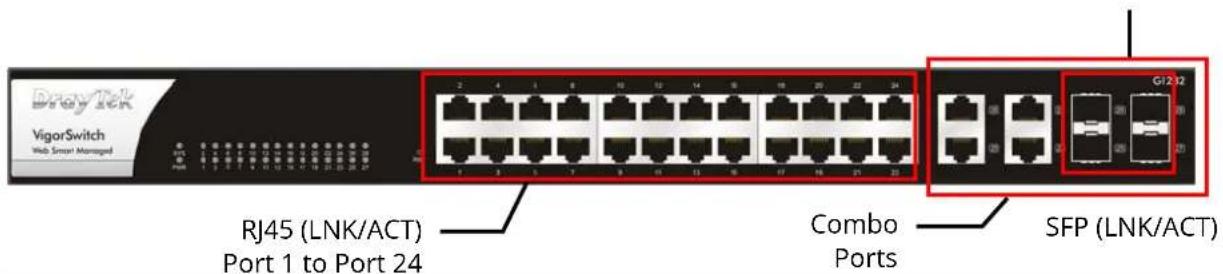
| LED | Status Explanation | |
| SYS | On (Green) The switch finishes system booting and the system is ready. | |
| Blinking (Green) The switch is powered on and starts system booting. | ||
| Off The power is off or the system is not ready / malfunctioning. | ||
| PWR | On (Green) The device is powered on and running normally. | |
| Off The device is not ready or is failed. | ||
| RJ45 (LNK/ACT) Port 1 ~ 24 | On (Green) The device is connected | |
| Blinking The system is sending or receiving data through the port. | ||
| Off The port is disconnected or the link is failed. | ||
| Combo Ports 25 ~ 28 RJ45 / SFP (LNK/ACT) | On (Green) The device is connected with 1000Mbps. | |
| On (Amber) The device is connected with 10/100Mbps. | ||
| Blinking The system is sending or receiving data through the port. | ||
| Off The port is disconnected or the link is failed. | ||
| Interface Description | |
| RJ 45 LNK/ACT Port 1 ~ 24 | Port 1 to Port 24 can be used for Ethernet connection |
| SFP LNK/ACT Port 25 ~ 28 | Port 25 to Port 28 are used for fiber connection. |
| Power inlet for AC input (100~240V/AC, 50/60Hz). |
I-2 Installation
Before starting to configure the switch, you have to connect your devices correctly.
Note:
For the sake of personal safety, only trained and qualified personnel should install this device.
I-2-1 Rack-Mounted Installation
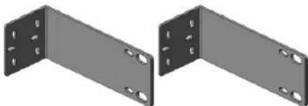
The switch can be installed easily by using rack mount kit.
natural_image
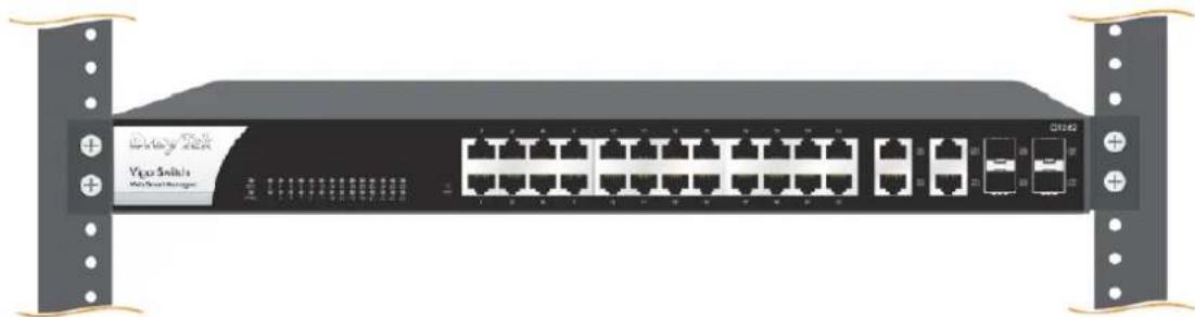
Two identical metal L-bracket components with mounting holes, shown side by side (no text or symbols)- Attach the brackets to the chassis of a 19-inch rack. The second bracket attaches the other side of the chassis as above procedure.
- After the bracket installation, the VigorSwitch's chassis can be installed in a rack by using four screws for each side of the rack.
natural_image
Front view of a network switch device with multiple Ethernet ports and drive cables (no visible text or labels)I-2-3 Typical Applications
The VigorSwitch implements 24 Gigabit Ethernet TP ports with auto MDIX and four slots for the removable module supporting comprehensive fiber types of connection, including LC and BiDi-LC SFP modules. The switch is suitable for the following applications:
Case 1: All switch ports are in the same local area network.
Every port can access each other. (*The switch image is sample only.)
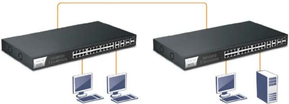
If VLAN is enabled and configured, each node in the network that can communicate each other directly is bounded in the same VLAN area.
Here VLAN area is defined by what VLAN you are using. The switch supports both port-based VLAN and tag-based VLAN. They are different in practical deployment, especially in physical location. The following diagram shows how it works and what the difference they are.
Case 2: Port-based VLAN -1 (*The switch image is sample only.)
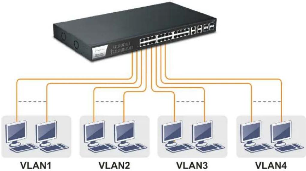
flowchart
graph TD
    A["Switch"] --> B["VLAN1"]
    A --> C["VLAN2"]
    A --> D["VLAN3"]
    A --> E["VLAN4"]
    B --> F["Computer 1"]
    B --> G["Computer 2"]
    C --> H["Computer 3"]
    C --> I["Computer 4"]
    D --> J["Computer 5"]
    E --> K["Computer 6"]
- The same VLAN members could not be in different switches.
• Every VLAN members could not access VLAN members each other. - The switch manager has to assign different names for each VLAN groups at one switch.
Case 3: Port-based VLAN - 2
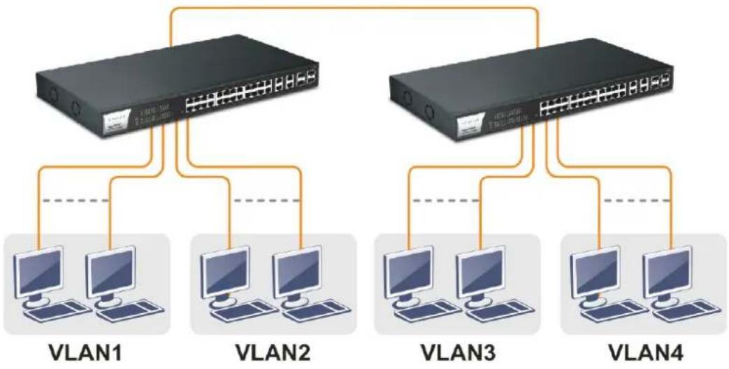
flowchart
graph TD
    A["Router 1"] --> B["VLAN1"]
    A --> C["VLAN2"]
    A --> D["VLAN3"]
    A --> E["VLAN4"]
    B --> F["Computer 1"]
    B --> G["Computer 2"]
    C --> H["Computer 3"]
    C --> I["Computer 4"]
    D --> J["Computer 5"]
    D --> K["Computer 6"]
    E --> L["Computer 7"]
    E --> M["Computer 8"]
• VLAN1 members could not access VLAN2, VLAN3 and VLAN4 members.
- VLAN2 members could not access VLAN1 and VLAN3 members, but they could access VLAN4 members.
• VLAN3 members could not access VLAN1, VLAN2 and VLAN4.
- VLAN4 members could not access VLAN1 and VLAN3 members, but they could access VLAN2 members.
Case 4: The same VLAN members can be at different switches with the same VID
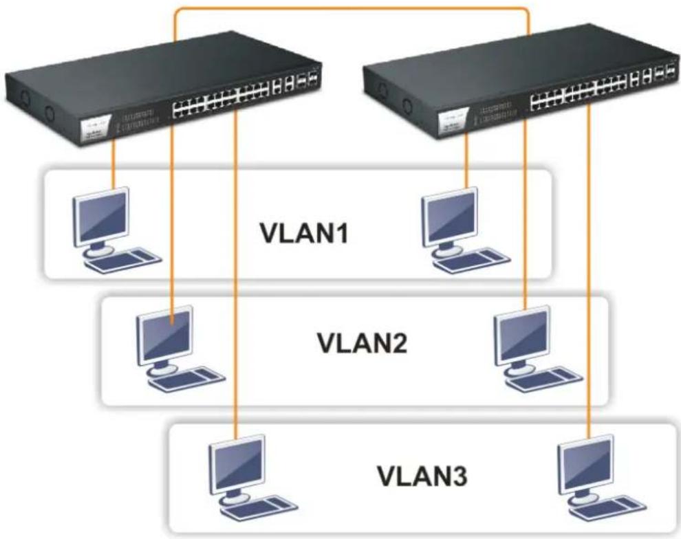
flowchart
graph TD
    A["Router 1"] -->|VLAN1| B["Computer 1"]
    C["Router 2"] -->|VLAN2| D["Computer 2"]
    E["Router 3"] -->|VLAN3| F["Computer 3"]
Case 5: Desktop Installation
- Install the switch on a level surface that can support the weight of the unit and the relevant components.
- Plug the switch with the female end of the provided power cord and plug the male end to the power outlet.
Case 6: Central Site/Remote site application is used in carrier or ISP
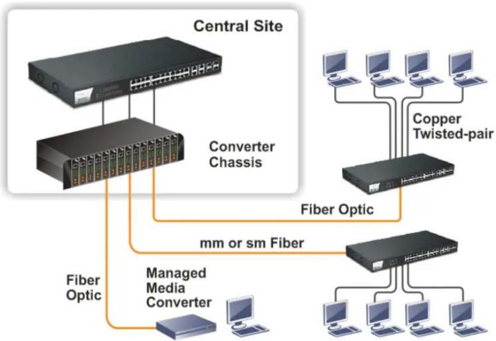
flowchart
graph TD
    A["Central Site"] --> B["Converter Chassis"]
    A --> C["Fiber Optic"]
    A --> D["mm or sm Fiber"]
    A --> E["Managed Media Converter"]
    A --> F["Copper Twisted-pair"]
    A --> G["Computer"]
    A --> H["Computer"]
    A --> I["Computer"]
Case 7: Peer-to-peer application is used in two remote offices
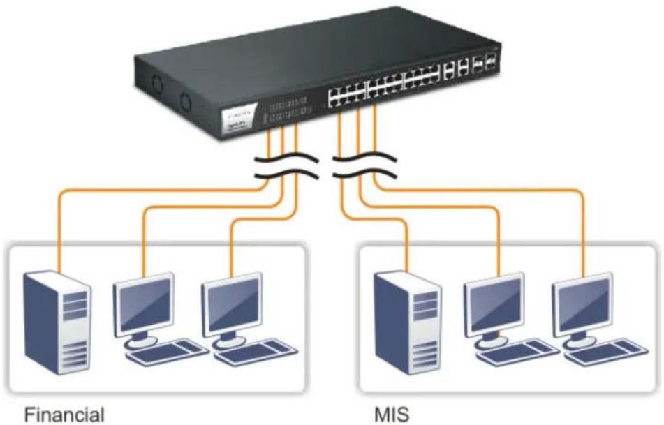
flowchart
graph TD
    A["Server"] --> B["Client 1"]
    A --> C["Client 2"]
    A --> D["Client 3"]
    A --> E["Client 4"]
    A --> F["Client 5"]
    A --> G["Client 6"]
    A --> H["Client 7"]
    A --> I["Client 8"]
    A --> J["Client 9"]
    A --> K["Client 10"]
    A --> L["Client 11"]
    A --> M["Client 12"]
    A --> N["Client 13"]
    A --> O["Client 14"]
    A --> P["Client 15"]
    A --> Q["Client 16"]
    A --> R["Client 17"]
    A --> S["Client 18"]
    A --> T["Client 19"]
    A --> U["Client 20"]
    A --> V["Client 21"]
    A --> W["Client 22"]
    A --> X["Client 23"]
    A --> Y["Client 24"]
    A --> Z["Client 25"]
Case 8: Office network
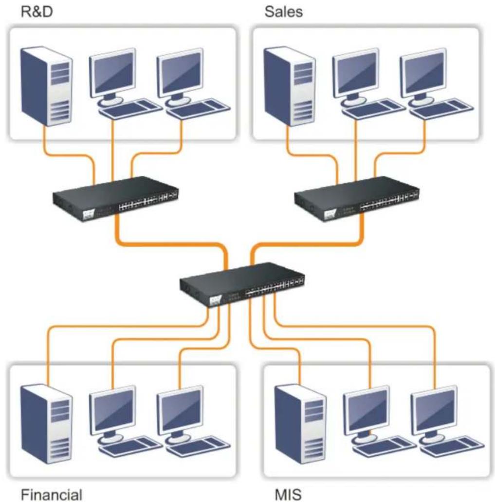
flowchart
graph TD
    subgraph R&D
        A1["Computer 1"] --> B1["Server"]
        A2["Computer 2"] --> B1
        A3["Computer 3"] --> B1
        B1 --> C1["Server"]
        C1 --> D1["Switch"]
    end
    subgraph Sales
        E1["Computer 4"] --> F1["Server"]
        E2["Computer 5"] --> F1
        E3["Computer 6"] --> F1
        F1 --> G1["Switch"]
    end
    H1["Computer 7"] --> I1["Server"]
    H2["Computer 8"] --> I1
    H3["Computer 9"] --> I1
    I1 --> J1["Switch"]
    style R&D fill:#f9f,stroke:#333
    style Sales fill:#bbf,stroke:#333
I-2-4 Configuring the Management Agent of Switch
Users can monitor and configure the switch through the following procedures.
Configuring the Management Agent of VigorSwitch G1282 through the Ethernet Port.
There are several ways to configure and monitor the switch through Ethernet port, includes Web-UI and SNMP.
VigorSwitch, for example:
IP Address: 192.168.1.224
Subnet Mask: 255.255.255.0
Default Gateway: 192.168.1.254
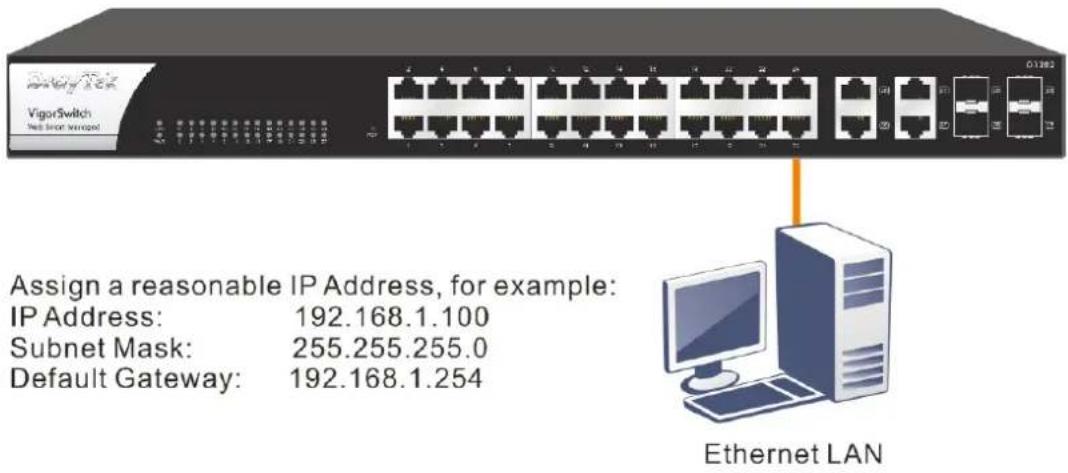
I-2-5 Managing VigorSwitch G1282 through Ethernet Port
Before start using the switch, the IP address setting of the switch should be done, then perform the following steps:
- Set up a physical path between the configured the switch and a PC by a qualified UTP Cat. 5e cable with RJ-45 connector.
Note:
If PC directly connects to the switch, you have to setup the same subnet mask between them. But, subnet mask may be different for the PC in the remote site. Please refer to the above figure about the Web Smart Switch default IP address information.
- After configuring correct IP address on your PC, open your web browser and access switch's IP address.
Default system account is "admin", with password "admin" in default. Switch IP address is "192.168.1.224" by default with DHCP client enabled.
I-2-6 IP Address Assignment
For IP address configuration, there are three parameters needed to be filled in. They are IP address, Subnet Mask, Default Gateway and DNS.
IP address:
The address of the network device in the network is used for internetworking communication. Its address structure looks is shown below. It is “classful” because it is split into predefined address classes or categories.
Each class has its own network range between the network identifier and host identifier in the 32 bits address. Each IP address comprises two parts: network identifier (address) and host identifier (address). The former indicates the network where the addressed host resides, and the latter indicates the individual host in the network which the address of host refers to. And the host identifier must be unique in the same LAN. Here the term of IP address we used is version 4, known as IPv4.
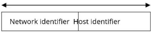
32 bits
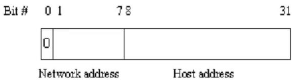
With the classful addressing, it divides IP address into three classes, class A, class B and class C. The rest of IP addresses are for multicast and broadcast. The bit length of the network prefix is the same as that of the subnet mask and is denoted as IP address/X, for example, 192.168.1.0/24. Each class has its address range described below.
Class A:
Address is less than 126.255.255.255. There are a total of 126 networks can be defined because the address 0.0.0.0 is reserved for default route and 127.0.0.0/8 is reserved for loopback function.
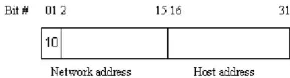
Class B:
IP address range between 128.0.0.0 and 191.255.255.255. Each class B network has a 16-bit network prefix followed 16-bit host address. There are 16,384 (2^14)/16 networks able to be defined with a maximum of 65534 (2^16 -2) hosts per network.
Class C:
IP address range between 192.0.0.0 and 223.255.255.255. Each class C network has a 24-bit network prefix followed 8-bit host address. There are 2,097,152 (2^21)/24 networks able to be defined with a maximum of 254 (2^8 -2) hosts per network.
Bit#0123
23 24 31
| 110 |
Network address
Host address
Class D and E:
Class D is a class with first 4 MSB (Most significance bit) set to 1-1-1-0 and is used for IP Multicast. See also RFC 1112. Class E is a class with first 4 MSB set to 1-1-1-1 and is used for IP broadcast.
According to IANA (Internet Assigned Numbers Authority), there are three specific IP address blocks reserved and able to be used for extending internal network. We call it Private IP address and list below:
| Class A 10.0.0.0 --- 10.255.255.255 |
| Class B 172.16.0.0 --- 172.31.255.255 |
| Class C 192.168.0.0 --- 192.168.255.255 |
Please refer to RFC 1597 and RFC 1466 for more information.
Subnet mask:
It means the sub-division of a class-based network or a CIDR block. The subnet is used to determine how to split an IP address to the network prefix and the host address in bitwise basis. It is designed to utilize IP address more efficiently and ease to manage IP network.
For a class B network, 128.1.2.3, it may have a subnet mask 255.255.0.0 in default, in which the first two bytes is with all 1s. This means more than 60 thousands of nodes in flat IP address will be at the same network. It's too large to manage practically. Now if we divide it into smaller network by extending network prefix from 16 bits to, say 24 bits, that's using its third byte to subnet this class B network. Now it has a subnet mask 255.255.255.0, in which each bit of the first three bytes is 1. It's now clear that the first two bytes is used to identify the class B network, the third byte is used to identify the subnet within this class B network and, of course, the last byte is the host number.
Not all IP address is available in the sub-netted network. Two special addresses are reserved. They are the addresses with all zero's and all one's host number. For example, an IP address 128.1.2.128, what IP address reserved will be looked like? All 0s mean the network itself, and all 1s mean IP broadcast.
128.1.2.128/25
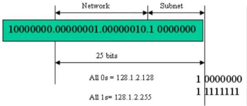
In this diagram, you can see the subnet mask with 25-bit long, 255.255.255.128, contains 126 members in the sub-netted network. Another is that the length of network prefix equals the number of the bit with 1s in that subnet mask. With this, you can easily count the number of IP addresses matched. The following table shows the result.
Prefix Length No. of IP matched No. of Addressable IP
| /32 | 1 | - | |
| /31 | 2 | - | |
| /30 | 4 | 2 | |
| /29 | 8 | 6 | |
| /28 | 16 | 14 | |
| /27 | 32 | 30 | |
| /26 | 64 | 62 | |
| /25 | 128 | 126 | |
| /24 | 256 | 254 | |
| /23 | 512 | 510 | |
| /22 | 1024 | 1022 | |
| /21 | 2048 | 2046 | |
| /20 | 4096 | 4094 | |
| /19 | 8192 | 8190 | |
| /18 | 16384 | 16382 | |
| /17 | 32768 | 32766 | |
| /16 | 65536 | 65534 |
According to the scheme above, a subnet mask 255.255.255.0 will partition a network with the class C. It means there will have a maximum of 254 effective nodes existed in this sub-netted network and is considered a physical network in an autonomous network. So it owns a network IP address which may looks like 168.1.2.0.
With the subnet mask, a bigger network can be cut into small pieces of network. If we want to have more than two independent networks in a worknet, a partition to the network must be performed. In this case, subnet mask must be applied.
For different network applications, the subnet mask may look like 255.255.255.240. This means it is a small network accommodating a maximum of 15 nodes in the network.
For assigning an IP address to the switch, you just have to check what the IP address of the network will be connected with the switch. Use the same network address and append your host address to it.
- First, IP Address: as shown above, enter "192.168.1.224", for instance. For sure, an IP address such as 192.168.1.x must be set on your PC.
- Second, Subnet Mask: as shown above, enter "255.255.255.0". Choose a subnet mask suitable for your network.
Note:
The DHCP Setting is enabled in default. Therefore, if a DHCP server presented on network connected to the switch, check before accessing your switch is essential.
I-3 Accessing Web Page of VigorSwitch
- Open any browser (e.g., Firefox) and type "192.168.1.224" as URL.
- Please enter "admin/admin" as the Username/Password and click Login.
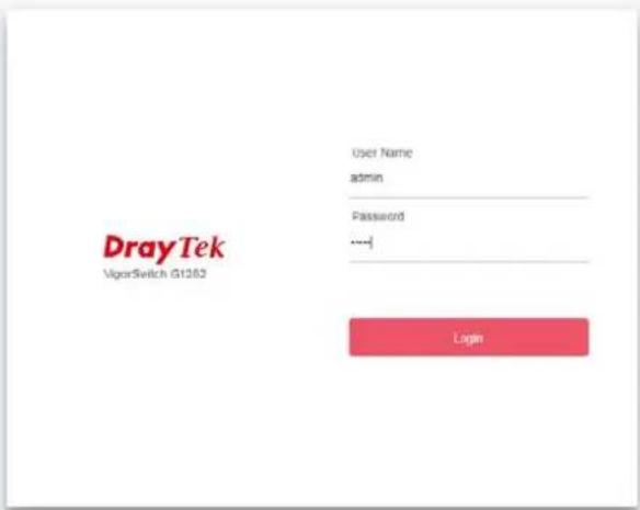
- Now, the Main Screen will appear.
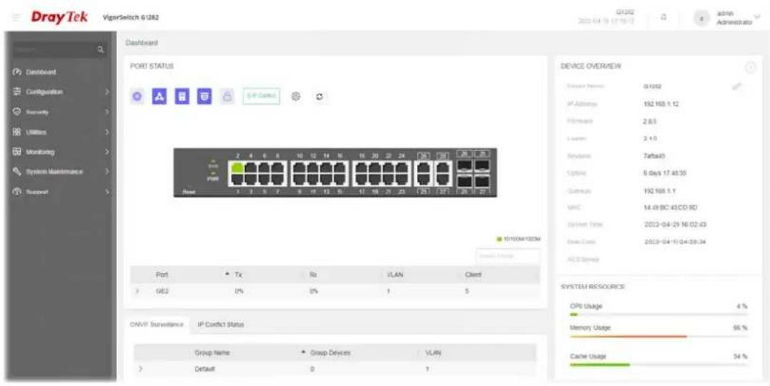
i Info:
The DHCP Setting is enabled in default. Therefore, if a DHCP server presented on network connected to VigorSwitch, checking before accessing VigorSwitch is essential.
I-4 Dashboard
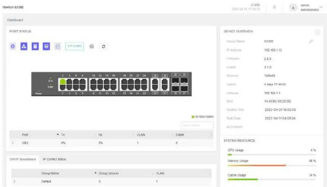
Click Dashboard from the main menu on the left side of the main page.
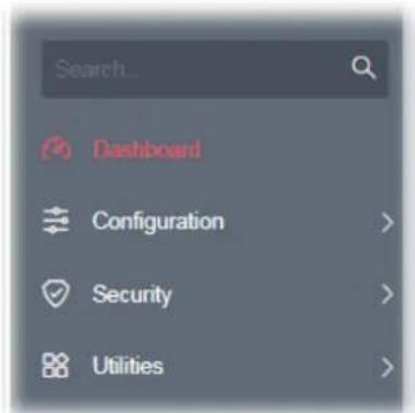
A web page with default selections will be displayed on the screen. Refer to the following figure:
Chapter II Configuration

natural_image
Red gear icon enclosed in a circular arrow, no text or symbols presentII-1 General Setup
II-1-1 Mirroring
This section provides ability to mirror packets coming in or going out on any port to a destination port. Through the packet duplication in the destination port, this feature is convenient for system administrator to monitor / understand the traffic operation.
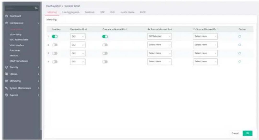
Available settings are explained as follows:
| Item | Description |
| Enabled | Enable / Disable - Click the toggle to enable / disable this function. - means “Enable”. - means “Enable”. - means “Disable”. - means “Disable”. |
| Destination Port Specify the port where you wish to observe the mirrored packets. | |
| Operate as Normal Port | Enable / Disable - Click the toggle to enable / disable this function. - means “Enable”. - means “Enable”. - means “Disable”. - means “Disable”. |
| Rx/Tx Source Mirrored Port | Select the port(s) which you wish to mirror the traffic, Rx for mirror the packets into the port, Tx for mirror the packets going out from the port. |
| Option |  - Clear current settings and return to factory default settings. - Clear current settings and return to factory default settings. |
After finishing this web page configuration, please click OK to save the settings.
II-1-2 Link Aggregation
LAG means Link Aggregation Group which groups some physical ports together to make a single high-bandwidth data path. Thus it can implement traffic load sharing among the member ports in a group to enhance the connection reliability.
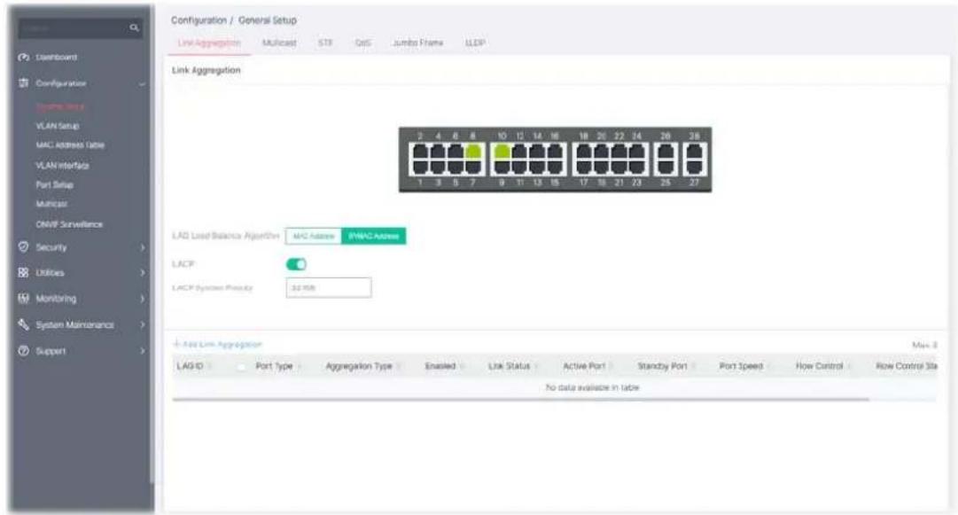
Available settings are explained as follows:
| Item | Description |
| Link Aggregation | |
| LAG Load Balance Algorithm | Select your Load balance algorithm.MAC address- Aggregated group will balance the traffic based on different MAC addresses. Therefore, the packets from different MAC addresses will be sent to different links.IP/Mac Address- Aggregated group will balance the traffic based on MAC addresses and IP addresses. Therefore, the packets from same MAC addresses but different IP addresses will be sent to different links. |
| LACP | Enable / Disable- Click the toggle to enable / disable this function. - means “Enable”. - means “Enable”. - means “Disable”. - means “Disable”. |
| LACP System Priority | The priority is used to determine which switch (local or remote) on the LAG connection is able to decide LACP activities. The lower the number is, the higher the priority for VigorSwitch will be. Therefore, the switch with the highest system priority (e.g., 1) can make decisions about which ports actively participate in LAG at a given time. |
| +Add Link Aggregation | Click to open the setting page of creating Link Aggregation. |
To add a link aggregation, click the "+Add Link Aggregation" to open the edit page.
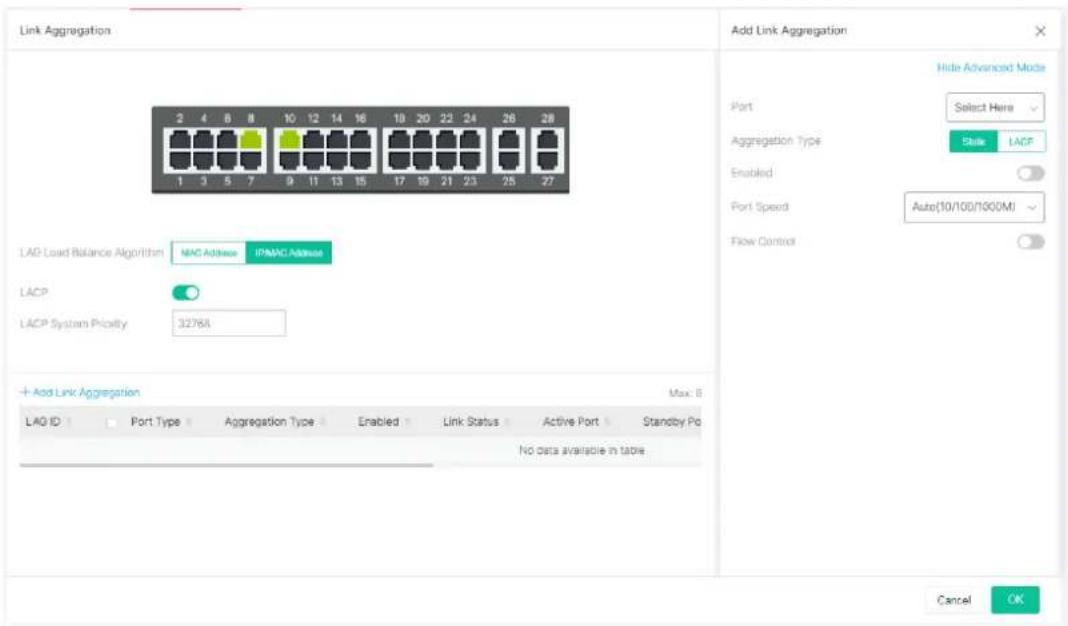
Available settings are explained as follows:
| Item | Description |
| Add/Edit Link Aggregation | |
| Show/Hide Advanced Mode | Click to switch different modes. |
| Port Select the interface(s) to apply the function. | |
| Aggregation Type Specify the type for LAG. | |
| Static - The static aggregated port sends packets over active member without detecting or negotiating with remote aggregated port.LACP - The LACP aggregated ports place member into active only after negotiated with remote aggregated port for best reliability. | |
| Port Enable | Enable / Disable - Click the toggle to enable / disable this function.- means "Enable".- means "Disable". |
| Port Speed Port speed capabilities: | |
| Auto(10/100/1000M): Auto speed with all capabilities.Auto(10M): Auto speed with 10M ability only.Auto(100M): Auto speed with 100M ability only.Auto(1000M): Auto speed with 1000M ability only.10M: Force speed with 10M ability.100M: Force speed with 100M ability.1000M: Force speed with 1000M ability.Selecting Auto (auto-negotiation) allows one port to negotiate with a peer port automatically to obtain the connection speed and duplex mode that both ends support. When auto-negotiation is turned on, a port on the switch negotiates with the peer automatically to determine the connection speed and duplex mode. If the peer portdoes not support auto-negotiation or turns off this feature, the switch determines the connection speed by detecting the signal on the cable and using half duplex mode. When the switch's auto-negotiation is turned off, a port uses the pre-configured speed and duplex mode when making a connection, thus requiring you to make sure that the settings of the peer port are the same in order to connect.For SFP fiber module, you might need to manually configure the speed to match fiber module speed. | |
| Flow Control | Enable / Disable - Click the toggle to enable / disable this function.- means "Enable".- means "Disable".A concentration of traffic on a port decreases port bandwidth and overflows buffer memory causing packet discards and frame losses. Flow Control is used to regulate transmission of signals to match the bandwidth of the receiving port. The switch uses IEEE802.3x flow control in full duplex mode and backpressure flow control in half duplex mode. IEEE802.3x flow control is used in full duplex mode to send a pause signal to the sending port, causing it to temporarily stop sending signals when the receiving port memory buffers fill. Back Pressure flow control is typically used in half duplex mode to send a "collision" signal to the sending port (mimicking a state of packet collision) causing the sending port to temporarily stop sending signals and resend later. |
| OK Save the settings. | |
After finishing this web page configuration, please click OK to save the settings. The new link aggregation group will be shown on the page.
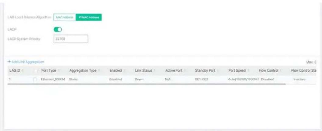
II-1-3 Multicast
For the multicast packets, this page allows the administrator to choose actions for processing the unknown multicast packets and for handling known packets with MAC address, IP address and VLAN ID.
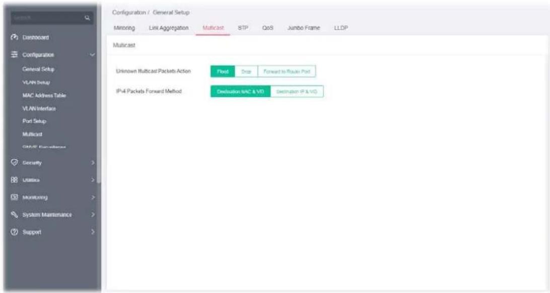
Available settings are explained as follows:
| Item | Description |
| Unknown Multicast Packets Action | Select an action for switch to handle with unknown multicast packet.Drop - Drop the unknown multicast data.Flood - Flood the unknown multicast data.Forward to Router Port - Forward the unknown multicast data to router port. |
| IPv4 Packets Forward Method | Set the IPv4 multicast forward method.Dst. MAC & VID - Forward using destination multicast MAC address and VLAN IDs.Dst. IP & VID - Forward using destination multicast IP address and VLAN ID. |
After finishing this web page configuration, please click OK to save the settings.
II-1-4 STP
The Spanning Tree Protocol (STP) is a network protocol that ensures a loop-free topology for any bridged Ethernet local area network.
Bridge Protocol Data Units (BPDUs) are frames that contain information about the Spanning Tree Protocol (STP). Switches send BPDUs using a unique MAC address from its origin port and a multicast address as destination MAC (01:80:C2:00:00:00, or 01:00:0C:CC:CC:CD for Per VLAN Spanning Tree).
For STP algorithms to function, the switches need to share information about themselves and their connections. What they share are bridge protocol data units (BPDUs).
BPDUs are sent out as multicast frames to which only other layer 2 switches or bridges are listening. If any loops (multiple possible paths between switches) are found in the network topology, the switches will co-operate to disable a port or ports to ensure that there are no loops; that is, from one device to any other device in the layer 2 network, only one path can be taken.
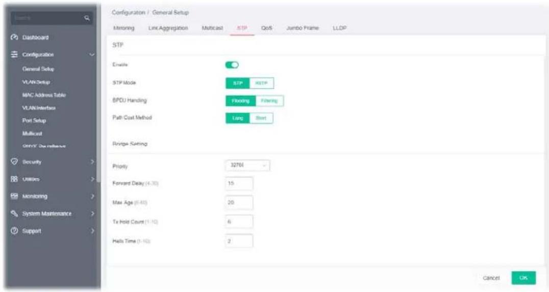
Available settings are explained as follows:
| Item | Description |
| STP | |
| Enable | Enable / Disable - Click the toggle to enable / disable this function.○ - means “Enable”.○ - means “Disable”. |
| STP Mode Set the operating mode of Spanning Tree (STP).STP - Enable the Spanning Tree (STP) operation.RSTP - Enable the Rapid Spanning Tree (RSTP) operation. | |
| BPDU Handling Specify the BPDU forward method when the STP is disabled.Filtering - Filter the BPDU when STP is disabled.Flooding - Flood the BPDU when STP is disabled. | |
| Path Cost Method Specify the path cost method.Long - Specifies that the default port path costs are within the range: 1~200,000,000.Short - Specifies that the default port path costs are within the range: | |
| 1~65,535. | |
| Bridge Setting - Negotiate with other VigorSwitch for determining the bridge switch. | |
| Priority | Specify the bridge priority. The valid range is from 0 to 61440, and the value should be the multiple of 4096. It ensures the probability that the switch is selected as the root bridge, and the lower value has the higher priority for the switch to be selected as the root bridge of the topology. |
| Forward Delay Specify the STP forward delay time, which is the amount of time that a port remains in the Listening and Learning states before it enters the Forwarding state. Its valid range is from 4 to 10 seconds. | |
| Max. Age Specify the time interval in seconds for a switch to wait the configuration messages, without attempting to redefine its own configuration. | |
| Tx Hold Count Specify the tx-hold-count used to limit the maximum numbers of packets transmission per second. The valid range is from 1 to 10. | |
| Hello Time Specify the STP hello time in second to broadcast its hello message to other bridge by Designated Ports. Its valid range is from 1 to 10 seconds. | |
After finishing this web page configuration, please click OK to save the settings.
II-1-5 QoS
QoS (Quality of Service) functions to provide different quality of service for various network applications and requirements and optimize the bandwidth resource distribution to provide a network service experience of better quality.
Queue Setting
VigorSwitch supports multiple queues for each interface. The higher numbered queue represents the higher priority. The following lists the types of supported priority queues:
- Strict Priority (SP) - Egress traffic from the higher priority queue will be transmitted first, lower priority queue shall wait until all traffic in SP queue is transmitted.
- Weighted Round Robin (WRR) - The number of packets sent from the queue is proportional to the weight of the queue.
CoS Mapping
It allows users to configure how ingress frames with CoS/802.1p tag map to QoS queues, and QoS queues to CoS/802.1p on egress frames.
Actual effectiveness is based on how QoS is configured in previous QoS section. This page provides settings for user to configure mapping only.
DSCP Mapping
It allows user to configure how ingress packets with DSCP tag map to QoS queues, and QoS queues to DSCP on egress packets.
Actual effectiveness is based on how QoS is configured in previous QoS section. This page provides settings for user to configure mapping only.
It allows user to configure how ingress packets with IP Precedence tag map to QoS queues, and QoS queues to IP Precedence on egress packets.
Actual effectiveness is based on how QoS is configured in previous QoS section. This page provides settings for user to configure mapping only.
Egress Shaping Rate
It allows a user to configure the egress port rate limit. The egress rate limit is the number of bits per second that can be received from the egress interface. Excess bandwidth above this limit is discarded.
Egress Shaping per Queue
It allows users to configure the maximum egress bandwidth not only by the port but also by specific QoS queues. The configuration result for each port will be displayed on the table listed on the lower side of this web page.
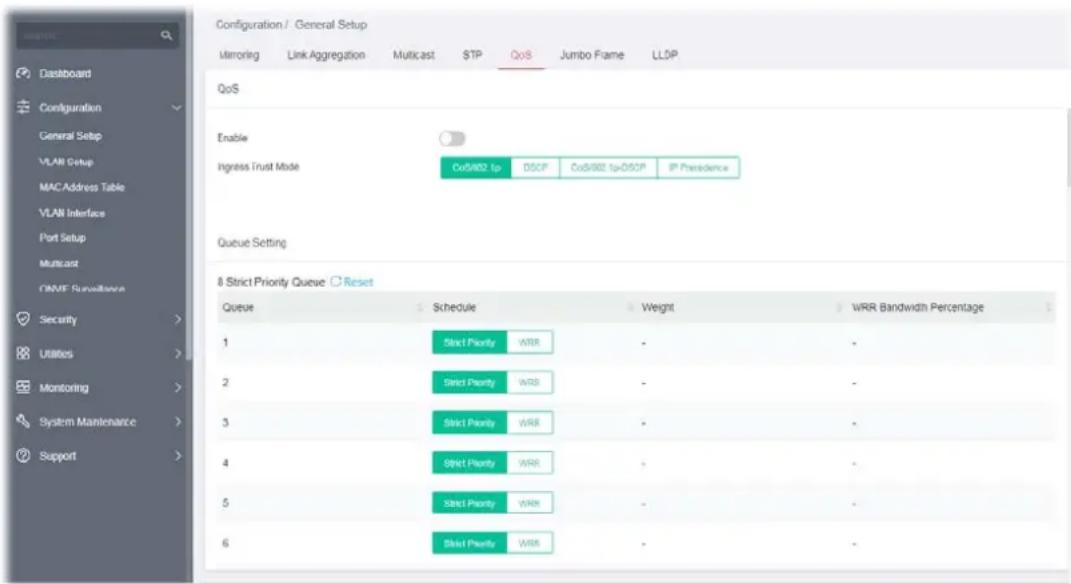
Available settings are explained as follows:
| Item | Description |
| QoS | |
| Enable | Enable / Disable - Click the toggle to enable / disable the function of QoS mode. - means “Enable”. - means “Enable”. - means “Disable”. - means “Disable”. |
| Ingress Trust Mode Select the QoS operation mode. | CoS/802.1p -Traffic is mapped to queues based on the CoS field in the VLAN tag, or based on the per-port default CoS value if there is no VLAN tag on the incoming packet.DSCP - All IP traffic is mapped to queues based on the DSCP field in the IP header. If traffic is not IP traffic, it is mapped to the lowest priority queue.CoS/802.1p-DSCP - All IP traffic is mapped to queues based on the DSCP field in the IP header. If traffic is not IP but has VLAN tag, mapped to queues based on the CoS value in the VLAN tag.IP Precedence - All IP traffic is mapped to queues based on the |
| DSCP field in the IP header. If traffic is not IP but has VLAN tag, mapped to queues based on the CoS value in the VLAN tag. | |
| Queue Setting | |
| Queue There are eight queue ID numbers allowed to be configured. | |
| Schedule | Strict Priority - Click it to set queue to strict priorityWRR - Click it to set queue to Weight round robin type. |
| Weight If the queue type is WRR, set the queue weight for the queue | |
| WRR Bandwidth Percentage | Displays the percentage of traffic which can be sent by current queue compared to total WRR queues. |
| CoS Mapping | |
| Class of Service Mapping to Queue (for Ingress Traffic) | Defines the queue ID (level 1 to 8) for different class of service values.Reset - Clear current settings and return to factory default settings. |
| Class of Service Mapping to Queue (for Egress Traffic Remark) | Defines the class of service value (0 to 7).Reset - Clear current settings and return to factory default settings. |
| DSCP Mapping | |
| DSCP Mapping to Queue (for Ingress Traffic) | Define the queue ID (level 1 to 8) for different DSCP values.Reset - Clear current settings and return to factory default settings. |
| DSCP Mapping to Queue (for Egress Traffic Remarking) | Define the DSCP value (0 to 63).Reset - Clear current settings and return to factory default settings. |
| IP Precedence Mapping | |
| IP Precedence Mapping to Queue (for Ingress Traffic) | Defines the queue ID (level 1 to 8) for different IP Precedence values.Reset - Clear current settings and return to factory default settings. |
| IP Precedence Mapping to Queue (for Egress Traffic Remarking) | Defines the IP Precedence value (0 to 7).Reset - Clear current settings and return to factory default settings. |
| Egress Shaping per Queue | Configure the maximum egress bandwidth not only by port but also by specific QoS queues.Reset - Clear all settings and return to factory default settings.Port - Display the port (GE1 to GE28) profiles.Option - Clear settings of the selected port and return to factory default settings.Edit - To modify the egress shaping rate for port profiles, select two (at least) GE ports to display the link. |
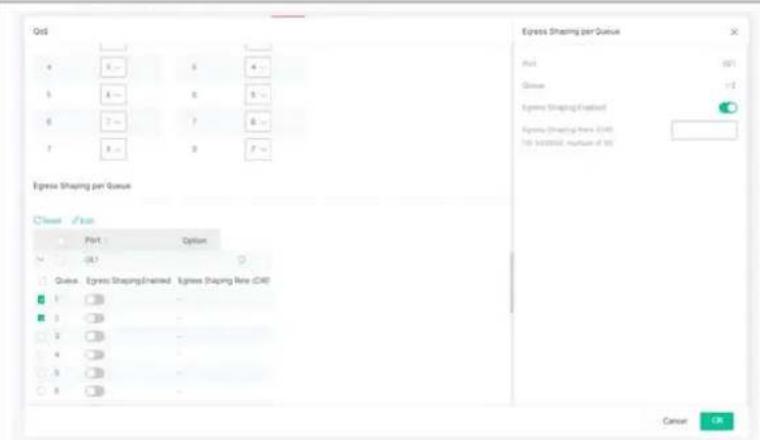
- Egress Shaping Enabled- Switch the toggle to enable/disable the setting.
- Egress Shaping Rate (CIR) - Enter the rate value, <16-1000000>, unit: 16 Kbps.
After finishing this web page configuration, please click OK to save the settings.
II-1-6 Jumbo Frame
This page allows a user to configure switch port jumbo frame settings.
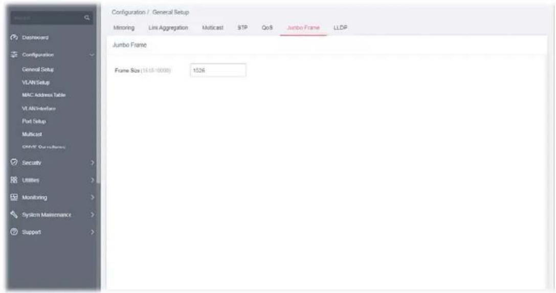
Available settings are explained as follows:
| Item | Description |
| Jumbo Frame | |
| Frame Size Enter Jumbo frame size. The valid range is 1526 bytes – 10000 bytes. | |
After finishing this web page configuration, please click OK to save the settings.
II-1-7 LLDP
This page allows a user to set general settings for LLDP.
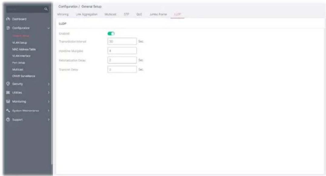
Available settings are explained as follows:
| Item | Description |
| LLDP | |
| Enable | Enable / Disable - Click the toggle to enable / disable this function. - means "Enable". - means "Enable". - means "Disable".If LLDP function is disabled, specify an action for the LLDP PDU packets.·Filtering - The LLDP packets will be filtered and deleted when LLDP is disabled.·Bridging - The LLDP packets will be bridging when LLDP is disabled.·Flooding - The LLDP packets will be flooded and forwarded to all interfaces when LLDP is disabled. - means "Disable".If LLDP function is disabled, specify an action for the LLDP PDU packets.·Filtering - The LLDP packets will be filtered and deleted when LLDP is disabled.·Bridging - The LLDP packets will be bridging when LLDP is disabled.·Flooding - The LLDP packets will be flooded and forwarded to all interfaces when LLDP is disabled. |
| Transmission Interval | Select the interval at which frames are transmitted. The default is 30 seconds, and the valid range is 5–32768seconds. |
| Holdtime Multiplier | Select the multiplier on the transmit interval to assign to TTL (range 2–10, default = 4). |
| Reinitialization Delay | Select the delay before a re-initialization (range 1–10 seconds, default = 2). |
| Transmit Delay Select the delay after an LLDP frame is sent (range 1–8192 seconds, default = 3). | |
II-2 VLAN Setup
A virtual local area network, virtual LAN or VLAN, is a group of hosts with a common set of requirements that communicate as if they were attached to the same broadcast domain, regardless of their physical location. A VLAN has the same attributes as a physical local area network (LAN), but it allows for end stations to be grouped together even if they are not located on the same network switch. VLAN membership can be configured through software instead of physically relocating devices or connections.
II-2-1 Existing VLAN
II-2-1-1 Default VLAN
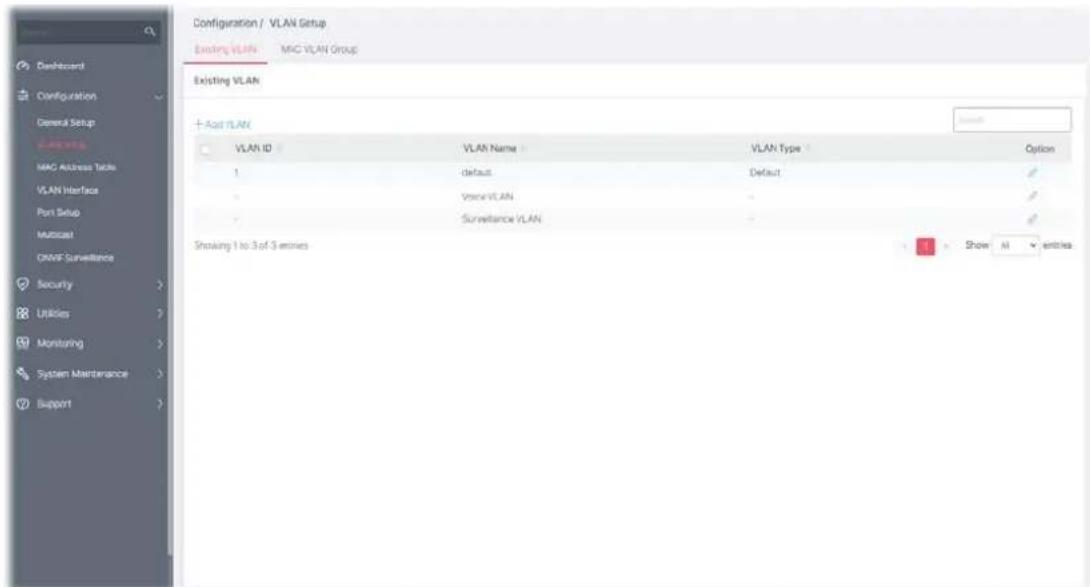
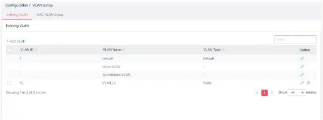
Available settings are explained as follows:
| Item | Description |
| +Add VLAN | Click to open the setting page of creating a new VLAN (with the same type of default VLAN). |
| VLAN ID Displays the ID number of the VLAN. | |
| VLAN Name Displays the name of the VLAN. | |
| VLAN Type Displays the type of the VLAN. | |
| Option | - Click to modify the setting page of the selected VLAN. |
To create a new VLAN, click +Add VLAN to open the following page.
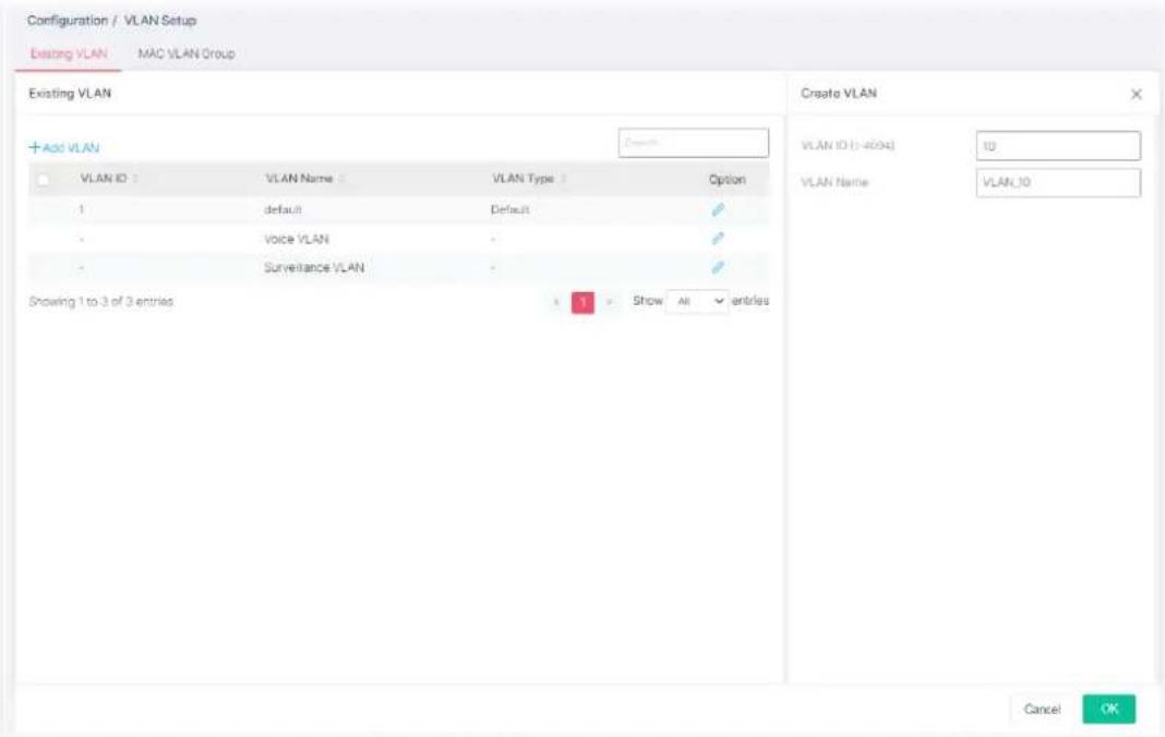
Available settings are explained as follows:
| Item | Description |
| Create VLAN | |
| VLAN ID Enter the number as VLAN ID to be created or deleted. If you want to create / delete multiple VLAN profiles, simply enter multiple VLAN ID separated by comma, and/or range of VLAN ID using hyphen. | |
| VLAN Name Enter the prefix you wish to add followed by VLAN ID as VLAN name.Leave it empty for using default "VLAN". | |
| OK Save the settings. | |
After finishing this web page configuration, please click OK to save the settings. A new VLAN will be shown on the page.
II-2-1-2 Voice VLAN
With this feature, a VLAN will be created temporarily and when the specified OUI device delivers protocol packets related to "VoIP", VigorSwitch will guide these packets into the specified Voice LAN with specified priority tag to speed up the packet transmission. Such voice VLAN is only active inside VigorSwitch for packet transmission. After these packets leave VigorSwitch, the Voice VLAN tag will be removed immediately.
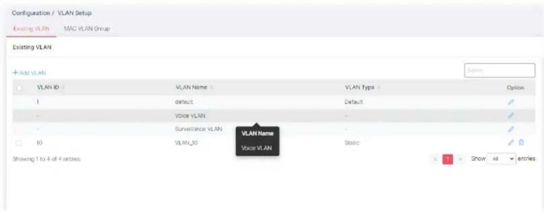
Click to open the editing page.
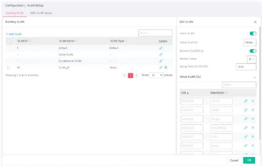
Available settings are explained as follows:
| Item | Description |
| Edit VLAN | |
| Voice VLAN | Enable / Disable - Click the toggle to enable / disable this function. ○ - means “Enable”.- means "Disable". |
| Voice VLAN ID Select Voice VLAN ID profile. | |
| Remark Cos/802.1p Click the toggle to enable / disable this function.Remark Value - If enabled, qualified packets will be remarked by this value. Specify the number of packets to be remarked. (0 to 7). The VoIP packets will be tagged with this number, so that QoS can prioritize it correctly. | |
| Aging Time | Select value of aging time (30~65536 min).Default is 1440 minutes. A voice VLAN entry will be age out after this time if without any packet pass through. |
| Voice VLAN OUI | Click the to display advanced settings. Default has 8 pre-defined OUI MAC.+Add - Click to create a new voice OUI.OUI - Enter the OUI address.Description - Enter a description of the specified MAC address to the voice VLAN OUI table.- Click it to modify the OUI settings and the description. |
| OK Save the settings. | |
After finishing this web page configuration, please click OK to save the settings.
II-2-1-3 Surveillance VLAN
Surveillance VLAN can be configured for VigorSwitch to identify the packets coming from an IP camera automatically and assign those traffics to a specific VLAN ID and CoS/802.1p value, this helps you to prioritize those traffics and improve video quality.
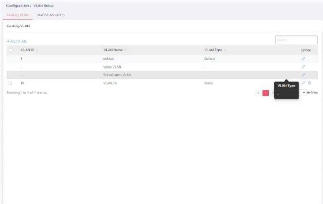
Click to open the editing page.
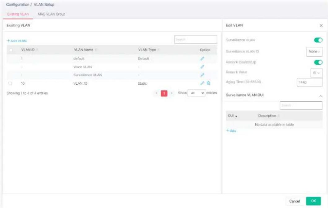
Available settings are explained as follows:
| Item | Description |
| Edit VLAN | |
| Surveillance VLAN | Enable / Disable - Click the toggle to enable / disable this function. - means "Enable". - means "Enable". - means "Disable". - means "Disable". the function to configure surveillance VLAN. the function to configure surveillance VLAN. |
Surveillance VLAN ID Cho  'LAN profile as Surveillance VLAN. 'LAN profile as Surveillance VLAN. | |
Remark Cos/802.1p Click t  gle to enable / disable this function. gle to enable / disable this function. k Value - If enabled, qualified packets will be remarked by this k Value - If enabled, qualified packets will be remarked by this  specify the number of packets to be remarked. (0 to 7). The specify the number of packets to be remarked. (0 to 7). The  rockets will be tagged with this number, so that QoS can I prioritize it correctly. rockets will be tagged with this number, so that QoS can I prioritize it correctly. | |
| Aging Time | [SZ32W] value of aging time (30~65536 min). Default is 1440 minutes. A voice VLAN entry will be age out after this time w without any packet pass through. Default is 1440 minutes. A voice VLAN entry will be age out after this time w without any packet pass through. |
| Surveillance VLAN OUI |  g Surveillance traffic is based on the OUI of the IP cameras. g Surveillance traffic is based on the OUI of the IP cameras. Click the √ to display advanced settings. Click the √ to display advanced settings. - ...Click to create a new OUI.[XYZ4] UI - Enter OUI MAC address of monitored IP camera. - ...Click to create a new OUI.[XYZ4] UI - Enter OUI MAC address of monitored IP camera. escription - Enter a description of the specified MAC address escription - Enter a description of the specified MAC address  the surveillance VLAN OUI table. the surveillance VLAN OUI table. Click to modify the OUI settings and the description. Click to modify the OUI settings and the description. |
| OK Save the settings. |  |
After finishing this web page configuration, please click OK to save the settings.
II-2-2 MAC VLAN Group
The MAC VLAN allows you to statically assign a VLAN ID to a host with specific MAC address(es). VigorSwitch allows you to configure multiple groups with configured MAC address and mask to be active on ports and to be bound with VLAN ID. This page allows the network administrator to define groups with specific MAC addresses for later binding with VLAN and Port.
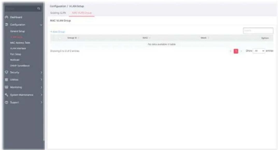
Available settings are explained as follows:
| Item | Description |
| MAC VLAN Group | |
| +Add Group Click to open the setting page of creating a new group. | |
| Group ID | It is a number for identification later, while chosen to be bound with VLAN/Port. |
| MAC Displays the MAC address of the device grouped under this VLAN profile. | |
| Mask Displays the number of the mask. | |
To add a MAC VLAN group, click the "+Add Group" to open the setting page.
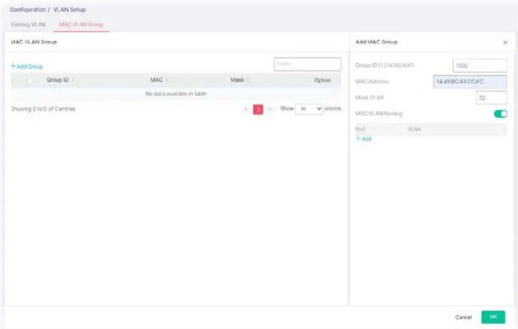
Available settings are explained as follows:
| Item | Description |
| Add MAC Group | |
| Group ID | It is a number for identification later, while chosen to be bound with VLAN/Port. |
| MAC Address Enter the MAC address you wish to be classified in this group. | |
| MASK | The mask is the length of matching prefix you wish to have on MAC address.For example, configure mask in 10. It means a host with beginning of the 10-digit of MAC address will be checked, and classified into this group if matched. |
| MAC VLAN Binding | The MAC VLAN allows you to statically assign a VLAN ID to a host with specific MAC address(es). VigorSwitch allows you to configure multiple groups with configured MAC address and mask to be active on ports and to be bound with VLAN ID. This page allows the network administrator to bind the group of specified MAC addresses with VLAN and Port.Enable / Disable - Click the toggle to enable / disable this function. - means "Enable". - means "Enable". - means "Disable".+Add - Click to enter a port number and VLAN ID number.Port - Select the ports you wish to be bound with specified MAC address group.VLAN - Enter the VLAN ID that you wish to be bound with. - means "Disable".+Add - Click to enter a port number and VLAN ID number.Port - Select the ports you wish to be bound with specified MAC address group.VLAN - Enter the VLAN ID that you wish to be bound with. |
After finishing this web page configuration, please click OK to save the settings.
A new group will be shown on the page.
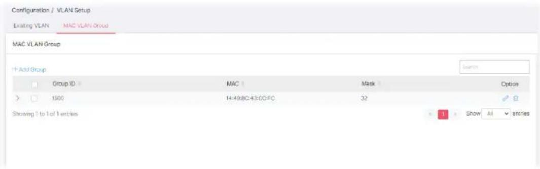
Available settings are explained as follows:
| Item | Description |
| Option | - Click to modify the settings of the selected group. - Click it to remove the selected entry. |
II-3 MAC Address Table
This section allows user to view the static MAC address entries in the MAC table, change related setting, and assign MAC address into MAC table.
II-3-1 Dynamic
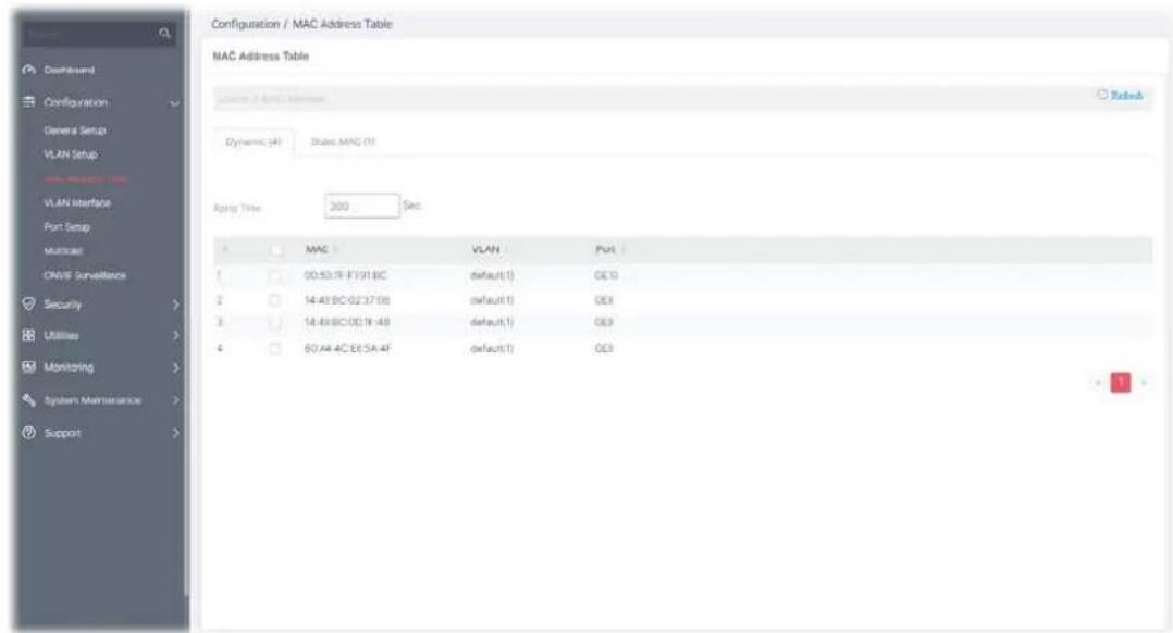
Available settings are explained as follows:
| Item | Description |
| Aging Time Enter the MAC address aging out value (5-32767 seconds). | |
| MAC | Displays the MAC address that will be forwarded. |
| VLAN | Displays the VLAN group to which the MAC address belongs. |
| Port Displays the port to which this MAC address belongs. | |
II-3-2 Static MAC
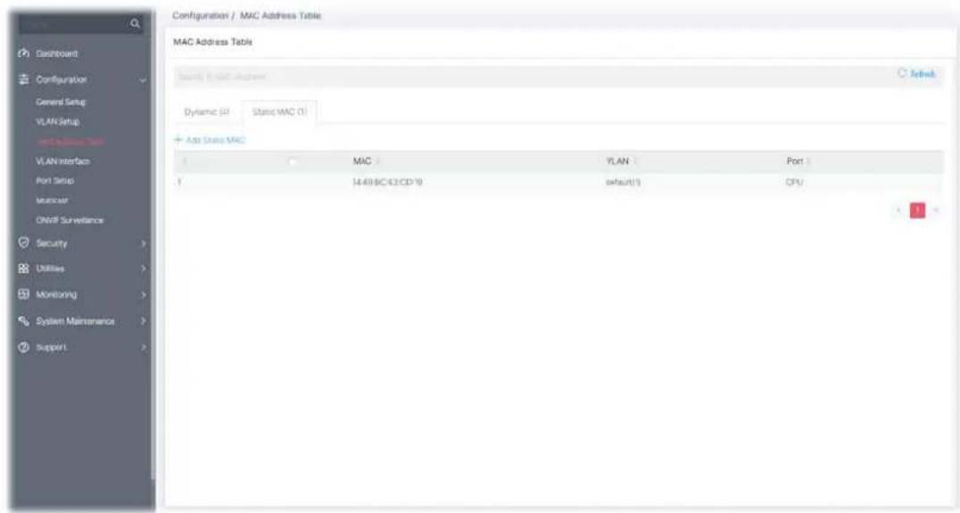
| Item | Description |
| +Add Static MAC Click it to add any port into the static MAC table. | |
| MAC | Displays the MAC address that will be forwarded. |
| VLAN | Displays the VLAN group to which the MAC address belongs. |
| Port Displays the port to which this MAC address belongs. | |
To add a static MAC, click the "+Add Static MAC" to open the edit page.
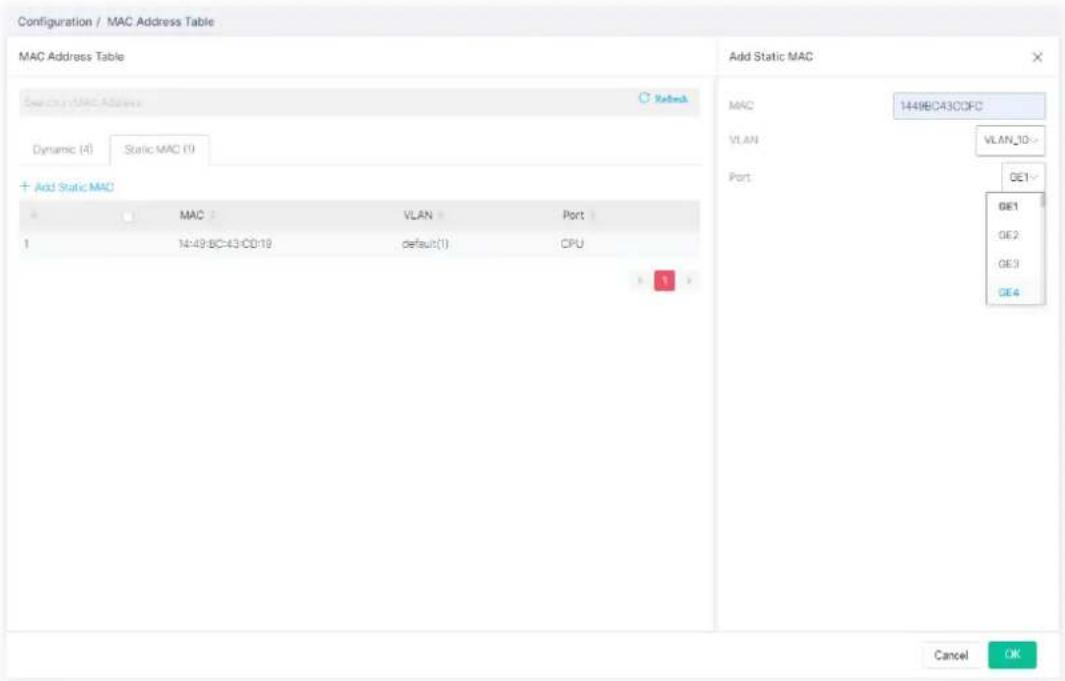
Available settings are explained as follows:
| Item | Description |
| Add Static MAC | |
| MAC Enter the MAC address that will be forwarded. | |
| VLAN Select the VLAN group to which the MAC address belongs. | |
| Port Select the port to which this MAC address belongs. | |
| OK | Save the settings. |
After finishing this web page configuration, please click OK to save the settings.
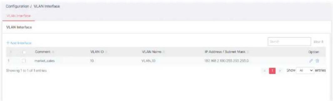
II-4 VLAN Interface
Different VLANs can communicate with each other. With the VLAN routing function, computers (or clients) under different VLANs (created from Configuration>>VLAN Setup) can access the Internet and share data or information with each other.
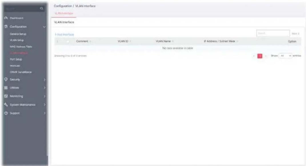
Available settings are explained as follows:
| Item | Description |
| +Add Interface Click to create a new VLAN interface profile. | |
| Comment Displays the brief comment for the VLAN ID. | |
| VLAN ID Displays the ID number of VLAN profile. | |
| VLAN Name Displays the name of the VLAN profile. | |
| IP Address/Subnet Mask | Displays the IP address and the subnet mask of the selected VLAN profile. |
To add a new interface, click the "+Add Interface" to open the edit page.
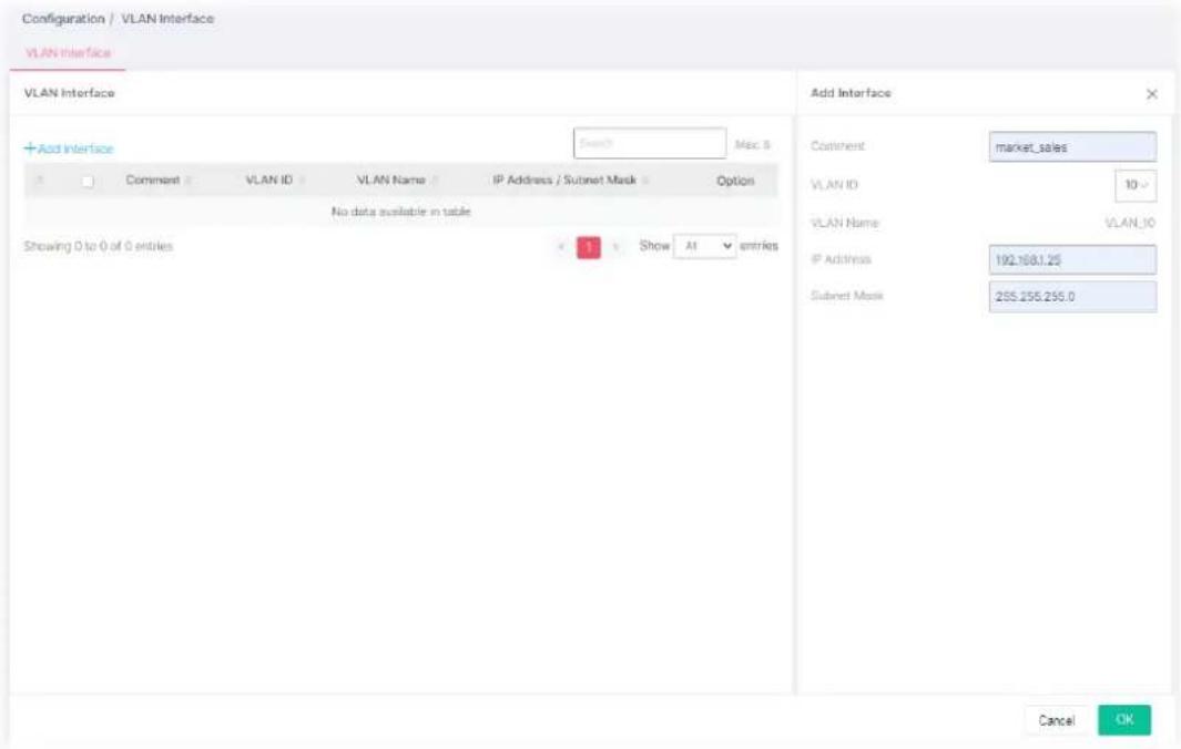
Available settings are explained as follows:
| Item | Description |
| Add Interface | |
| Comment Enter a brief comment for the VLAN ID. | |
| VLAN ID Use the drop down list to select one VLAN ID. | |
| VLAN Name Displays the name of the VLAN profile related to the VLAN ID number selected above. | |
| IP Address Enter the IP address for the selected VLAN ID. | |
| Subnet Mask Enter the subnet mask for the IP address set above. | |
After finishing this web page configuration, please click OK to save the settings.
II-5-1 General
This page allows a user to configure settings for PoE and configure priority of each port for supplying PoE power. While maximum power budget is reached, the power will be served starting with critical priority.
If the priority setting for all GE ports is configured as the same value (e.g., High); then, GE1 will have the highest priority to obtain PoE power in actual operation.
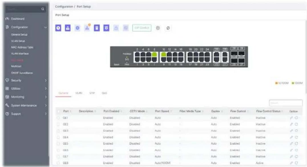
Available settings are explained as follows:
| Item | Description |
| Port | Displays the LAN ports (GE1 to GE28). |
| Description Displays the comment of the selected port. | |
| Port Enabled | Displays the status (Enabled or Disabled) of the LAN port. |
| CCTV Mode Displays if the function is enabled or disabled. | |
| Port Speed Displays the port speed capability. | |
| Link Status Displays the connection status. | |
| Fiber Media Type Displays the fiber media type of the LAN port. | |
| Duplex Displays the port duplex (auto/half/full) capability. | |
| Flow Control Config | Displays if the function of Flow Control Config is enabled or disabled. |
| Flow Control Status Displays the current operational status of Flow Control Config. | |
| EEE Enable Displays if the function of EEE is enabled or disabled. | |
| EEE State | Displays the current operational status of EEE. |
| Port Isolation | Displays if the function is enabled or disabled. |
| LCAP | Displays the priority number for the port. |
| Option | - Click it to modify the port setting.- Clear current settings and return to factory default settings. |
To modify settings for a port, click the link to open the setting page.
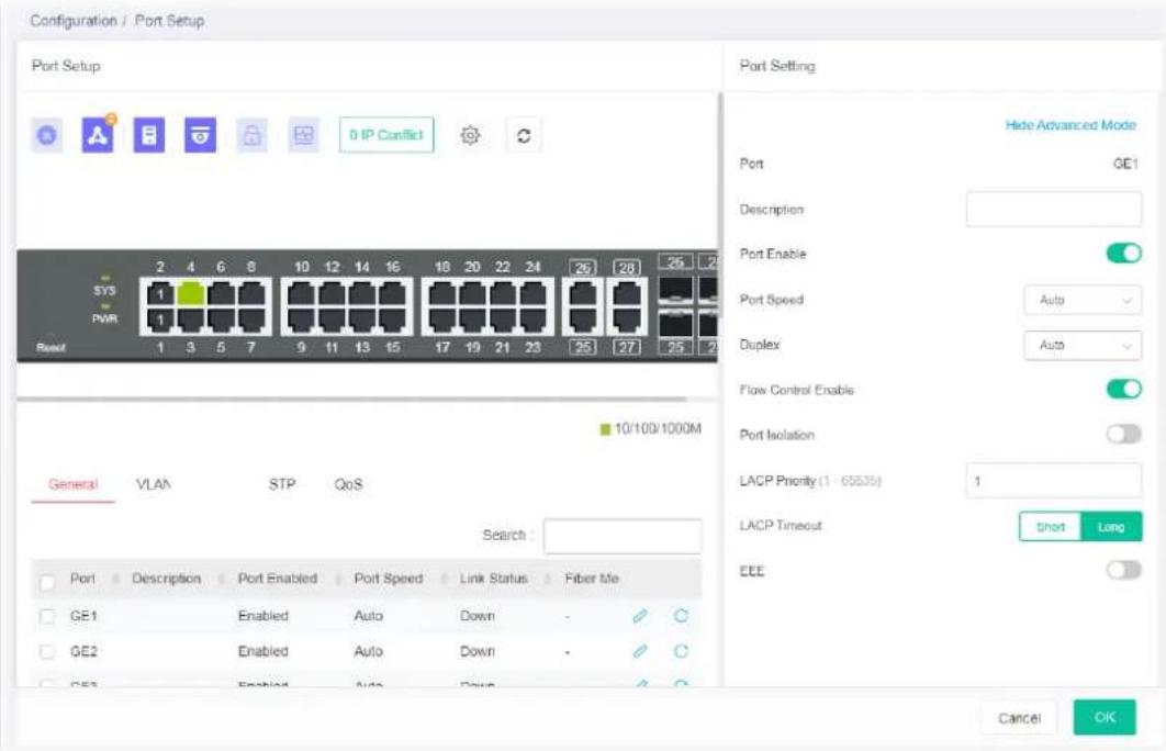
Available settings are explained as follows:
| Item | Description |
| Port Setting | |
| Show / Hide Advanced Mode | Click to display or hide the advanced settings. |
| Port Displays the port number. | |
| Description Enter a brief explanation for the selected port. | |
| Port Enable Enable/disable the settings of the selected port. | |
| Port Speed Port speed capabilities:Auto: Auto speed with all capabilities.Auto(10M): Auto speed with 10M ability only.Auto(100M): Auto speed with 100M ability only.Auto(1000M): Auto speed with 1000M ability only.Auto(10/100M): Auto speed with 10/100M ability.10M: Force speed with 10M ability. | |
| 100M: Force speed with 100M ability.1000M: Force speed with 1000M ability.Selecting Auto (auto-negotiation) allows one port to negotiate with a peer port automatically to obtain the connection speed and duplex mode that both ends support. When auto-negotiation is turned on, a port on the switch negotiates with the peer automatically to determine the connection speed and duplex mode. If the peer port does not support auto-negotiation or turns off this feature, the switch determines the connection speed by detecting the signal on the cable and using half duplex mode. When the switch's auto-negotiation is turned off, a port uses the pre-configured speed and duplex mode when making a connection, thus requiring you to make sure that the settings of the peer port are the same in order to connect.For SFP fiber module, you might need to manually configure the speed to match fiber module speed. | |
| Duplex | Port duplex capabilities:Auto: Auto duplex with all capabilities.Half: Auto speed with 10/100M ability only.Full: Auto speed with 10/100/1000M ability only. |
| Flow Control Enabled | A concentration of traffic on a port decreases port bandwidth and overflows buffer memory causing packet discards and frame losses. Flow Control is used to regulate transmission of signals to match the bandwidth of the receiving port. The switch uses IEEE802.3x flow control in full duplex mode and backpressure flow control in half duplex mode. IEEE802.3x flow control is used in full duplex mode to send a pause signal to the sending port, causing it to temporarily stop sending signals when the receiving port memory buffers fill. Back Pressure flow control is typically used in half duplex mode to send a "collision" signal to the sending port (mimicking a state of packet collision) causing the sending port to temporarily stop sending signals and resend later.Enable / Disable - Click the toggle to enable / disable this function. - means "Enable". - means "Enable". - means "Disable". - means "Disable". |
| Port Isolation | It allows the network administrator to configure protected port setting to prevent the selected ports from communication with each other. Port isolation is only allowed to communicate with unprotected port. For example, GE1 and GE3 are selected in Port List and Enable is clicked as port Isolation, then users behind GE1 and GE3 are separated and can not communicate with each other.Enable / Disable - Click the toggle to enable / disable this function. |
| LACP Priority Enter a port priority number for the port. | |
| LACP Timeout The timeout option decides how local switch of LAG connection determines connection to be lost. Switch would also notify the remote switch about this setting value, so that remote switch can send LACP PDU in correct timing.Short - LACP PDU will be sent per second. If port member is not seen over 3 seconds, it will cause port member timeout.Long - LACP PDU will be sent every 30 seconds. If port member is not seen over 90 seconds, it will cause port member timeout. | |
| EEE Enable or disable port EEE (Energy Efficient Ethernet) function for the | |
| selected port. | |
After finishing this web page configuration, please click OK to save the settings.
II-5-2 VLAN
This page allows a user to configure interface (GE) settings related to VLAN.
Voice VLAN
With voice VLAN, a VLAN will be created temporarily and when the specified OUI device delivers protocol packets related to "VoIP", VigorSwitch will guide these packets into the specified Voice LAN with specified priority tag to speed up the packet transmission. The voice VLAN is only active inside VigorSwitch for packet transmission. After these packets leave VigorSwitch, the Voice VLAN tag will be removed immediately.
Surveillance VLAN
Surveillance VLAN can be configured for VigorSwitch to identify the packets coming from an IP camera automatically and assign those traffics to a specific VLAN ID and CoS/802.1p value, this helps you to prioritize those traffics and improve video quality.
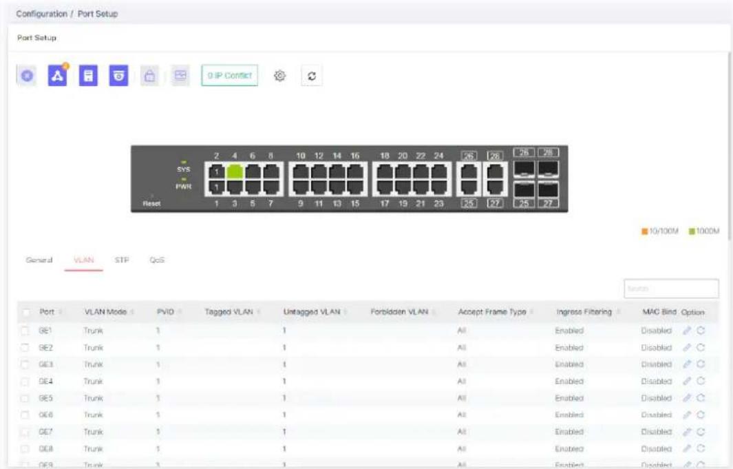
Available settings are explained as follows:
| Item | Description |
| Port Displays the LAN port number. | |
| Interface VLAN Mode Displays VLAN mode of the interface. | |
| PVID Displays the Port VLAN ID of the interface. | |
| Tagged VLAN Displays the VLAN profile (ID number) tagged in the VLAN interface. | |
| Untagged VLAN Displays the VLAN profile (ID number) untagged in the VLAN interface. | |
| Forbidden VLAN | Displays the VLAN profile (ID number) used by the VLAN interface. |
| Accept Frame Type Displays the acceptable-frame-type of the specified interfaces. | |
| Ingress Filtering | Displays the status (enabled/disabled) of ingress filtering function. |
| MAC Binding Displays the status (enabled/disabled) of MAC VLAN Binding function. | |
| Voice LAN State Displays the status (enabled/disabled) of Voice VLAN function. | |
| Option | - Click it to modify the VLAN interface settings.- Clear current settings and return to factory default settings. |
To modify settings for a port, click the link to open the setting page.
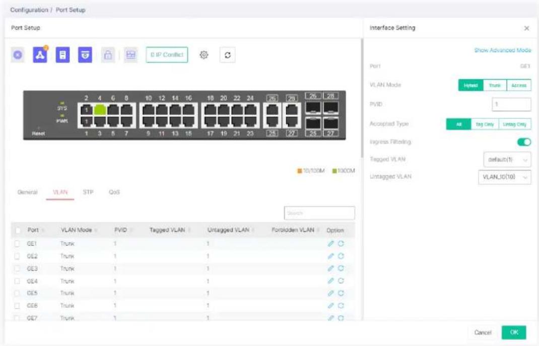
Available settings are explained as follows:
| Item | Description |
| Interface Setting | |
| Show / Hide Advanced Mode | Click to display or hide the advanced settings. |
| Port Displays the selected LAN port number. | |
| VLAN Mode | Select the VLAN mode of the interface.Hybrid – Support all functions as defined in IEEE 802.1Qspecification.Access – Accepts only untagged frames and join an untagged VLAN.Trunk - An untagged member of one VLAN at most, and is a tagged member of zero or more VLANs. |
| PVID | A PVID (Port VLAN ID) is a tag that adds to incoming untagged frames received on a port so that the frames are forwarded to the VLANgroup that the tag defines.For port under Access Mode, VLAN ID provided as PVID would automatically be selected as the untagged VLAN. |
| Accepted Type | Specify the acceptable-frame-type of the specified interfaces. It's only available with Hybrid mode.All - Accept frames regardless it's tagged with 802.1q or not.Tag Only - Accept frames only with 802.1q tagged.Untag Only - Accept frames untagged. |
| Ingress Filtering | Enable the ingress filtering to filter out any packets not belong to any VLAN members of this port. It is enabled automatically while operating in Access and Trunk mode. |
| Tagged VLAN Specify the | VLAN profile tagged in the VLAN. |
| Untagged VLAN Specify the | VLAN profile untagged in the VLAN. |
Below shows settings for Advanced Mode
| Forbidden VLAN | The selected GE port only allows default VLAN packet to pass through. Enable / Disable - Click the toggle to enable / disable the LAN port(s) as forbidden VLAN port. ○ - means “Enable”. ○ - means “Disable”. |
| Voice VLAN Enable | Enable / Disable - Click the toggle to enable / disable the LAN port(s) as Voice VLAN port. |
| Voice VLAN CoS Mode | All - Once this port is identified as Voice VLAN by frame with matched OUI, remark CoS/802.1p shall tag for all ingress frame regardless of remarked frame matched with pre-configured OUI or not. Src (Source) - Once this port is identified as Voice VLAN by frame with matched OUI, remark CoS/802.1p shall tag for only the matched ingress frame with pre-configured OUI. |
| Surveillance VLAN Enabled | Enable / Disable - Click the toggle to enable / disable the LAN port(s) as Surveillance VLAN port. |
| Surveillance VLAN Mode | Select port surveillance VLAN mode. Auto - Surveillance VLAN auto detect packets that match OUI table and add received port into surveillance VLAN ID tagged member. Manual - User need add interface to VLAN ID tagged member manually. |
| Surveillance VLAN QoS Policy | Select port QoS Policy mode. Video Packet - QoS attributes are applied to packets with OUI in the source MAC address. All - QoS attributes are applied to packets that are classified to the Surveillance VLAN. |
| MAC VLAN Binding Enable/disable the function of MAC VLAN Binding. | |
After finishing this web page configuration, please click OK to save the settings.
II-5-3 STP
The Spanning Tree Protocol (STP) is a network protocol that ensures a loop-free topology for any bridged Ethernet local area network.
Bridge Protocol Data Units (BPDUs) are frames that contain information about the Spanning Tree Protocol (STP). Switches send BPDUs using a unique MAC address from its origin port and a multicast address as destination MAC (01:80:C2:00:00:00, or 01:00:0C:CC:CC:CD for Per VLAN Spanning Tree).
For STP algorithms to function, the switches need to share information about themselves and their connections. What they share are bridge protocol data units (BPDUs).
BPDUs are sent out as multicast frames to which only other layer 2 switches or bridges are listening. If any loops (multiple possible paths between switches) are found in the network topology, the switches will co-operate to disable a port or ports to ensure that there are no loops; that is, from one device to any other device in the layer 2 network, only one path can be taken.
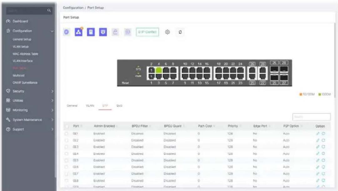
Available settings are explained as follows:
| Item | Description |
| Port Displays the LAN port number (GE1 to GE28). | |
| Admin Enabled Displays the status (enabled/disabled) of Admin Enabled. | |
| BPDU Filter Displays the status (enabled/disabled) of BPDU Filter function. | |
| BPDU Guard Displays the status (enabled/disabled) of BPDU Guard function. | |
| Path Cost Displays the value of transmitting a frame onto a LAN through that port. | |
| Priority Displays the priority value for the port interface. | |
| Edge Port Displays the status (enabled/disabled) of Edge Port function. | |
| P2P Option | Displays the STP of link type (All, Yes, No) on this port. |
| Option | - Click it to modify the STP port setting. |

- Clear current settings and return to factory default settings.
To modify settings for a port, click the

link to open the setting page.
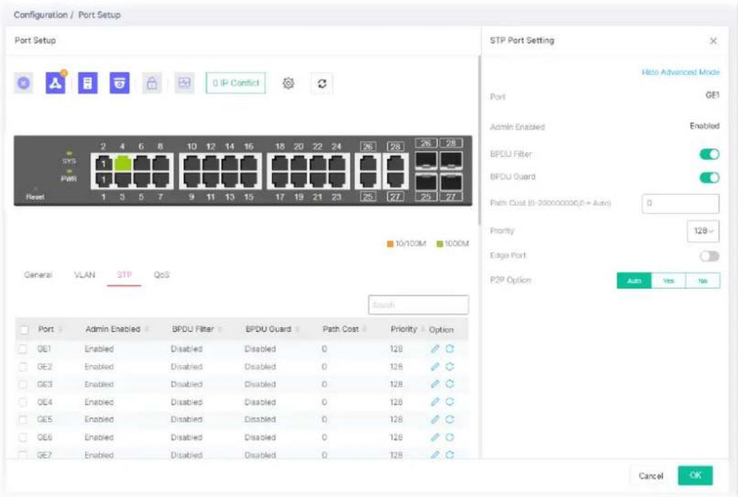
Available settings are explained as follows:
| Item | Description |
| STP Port Setting | |
| Show / Hide Advanced Mode | Click to display or hide the advanced settings. |
| Port Displays the selected | LAN port number. |
| Admin Enabled Displays the status of Admin Enabled. | |
| BPDU Filter | Click the toggle to enable / disable the function of dropping all BPDU packets and no BPDU will be sent. - means "Enable". - means "Enable". - means "Disable". - means "Disable". |
| BPDU Guard BPDU Guard further protects your switch by turning this port into error state and shutdown if any BPDU received from this port. Check it to enable such function. | |
| Path Cost | Path cost is the cost of transmitting a frame on to a LAN through that port. It is recommended to assign this value according to the speed of the bridge. The slower the media, the higher the cost. Entering 0 means the switch will automatically assign a value. |
| Priority | Specify a priority value for the switch. The smaller the priority value, the higher the priority and greater chance of becoming the root. |
| Edge Port | In the edge mode, the interface would be put into the Forwarding state immediately upon link up. If the edge mode is enabled for theinterface and there are BPDUs received on the interface, the loop might be occurred in the short time before the STP state change.Click the toggle to enable / disable the function. |
| P2P Option | Auto– VigorSwitch determines the STP of link type for this port automatically.Yes– It means the STP of link type on this port is full-duplex and directly connect to another switch or host.No- It means the STP of link type on this port is “not” full-duplex and “does not” directly connect to another switch or host. |
After finishing this web page configuration, please click OK to save the settings.
II-5-4 QoS
This page is used to configure port settings for QoS. The configuration result for each port will be displayed on the table listed on the lower side of this web page.
Ingress Rate Limit
It allows a user to configure ingress port rate limit. The ingress rate limit is the number of bits per second that can be received from the ingress interface. Excess bandwidth above this limit is discarded.
Egress Shaping Rate
It allows a user to configure egress port rate limit. The egress rate limit is the number of bits per second that can be received from the egress interface. Excess bandwidth above this limit is discarded.
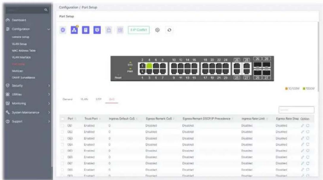
Available settings are explained as follows:
| Item | Description |
| Port Displays the port profiles (GE1 to GE28). | |
| Trust Port Displays if the traffic follow the trust mode in general setting (Enabled/Disabled). | |
| Ingress Default CoS | Displays the default CoS priority value for those ingress frames. |
| Egress Remark CoS Displays the status (Enabled/Disabled) of the function. | |
| Egress Remark DHCP/IP Precedence | Displays the status (Enabled/Disabled) of the function. |
| Ingress Rate Limit | Displays the value of the ingress rate limit. If this function is disabled, then Off will be shown instead. |
| Egress Rate Shaping | Displays the value of the egress rate shaping. If this function is disabled, then Off will be shown instead. |
| Option | - Click it to modify the QoS port setting. |

- Clear current settings and return to factory default settings.
To modify settings for a port, click the

link to open the setting page.
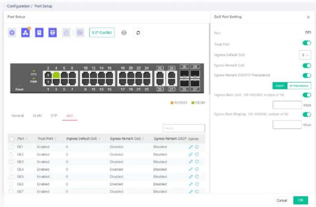
Available settings are explained as follows:
| Item | Description |
| QoS Port Setting | |
| Port Displays the port profiles (GE1 to GE28). | |
| Trust Port Enable / Disable - Click the toggle to enable / disable this function. | |
 - Traffic will follow trust mode in general setting. - Traffic will follow trust mode in general setting. | |
 - No QoS service for this port. - No QoS service for this port. | |
| Ingress Default CoS | Specify the default CoS priority value for those ingress frames without given trust QoS tag (802.1q/DSCP/IP Precedence, depending on configuration). |
| Egress Remark CoS | Enable / Disable - Click the toggle to enable / disable this function. |
| Egress Remark DSCP/IP Precedence | Click the toggle to enable / disable this function. |
| DSCP - Egress traffic will be marked with DSCP value according to the Queue to DSCP mapping table. | |
| IP Precedence - Egress traffic will be marked with IP Precedence value according to the Queue to IP Precedence mapping table. | |
| Ingress Rate Limit | The ingress rate limit is the number of bits per second that can be received from the ingress interface. Excess bandwidth above this limit is discarded. |
| Click the toggle to enable / disable this function. | |
| Enter the rate value,<16-1000000>,unit:16 Kbps. | |
| Egress Rate Shaping | The egress rate limit is the number of bits per second that can be received from the egress interface. Excess bandwidth above this limit is discarded.Click the toggle to enable / disable this function.Enter the rate value,<16-1000000>,unit:16 Kbps. |
After finishing this web page configuration, please click OK to save the settings.
IP multicast is a technique for one-to-many communication over an IP infrastructure in a network.
To avoid the incoming data broadcasting to all GE ports, multicast is useful to transfer the data/message to specified GE ports for IGMP snooping. When VigorSwitch receives a message "subscribed" by the client, it must decide to transfer the data to specified GE ports according to the location of the client (subscribed member).
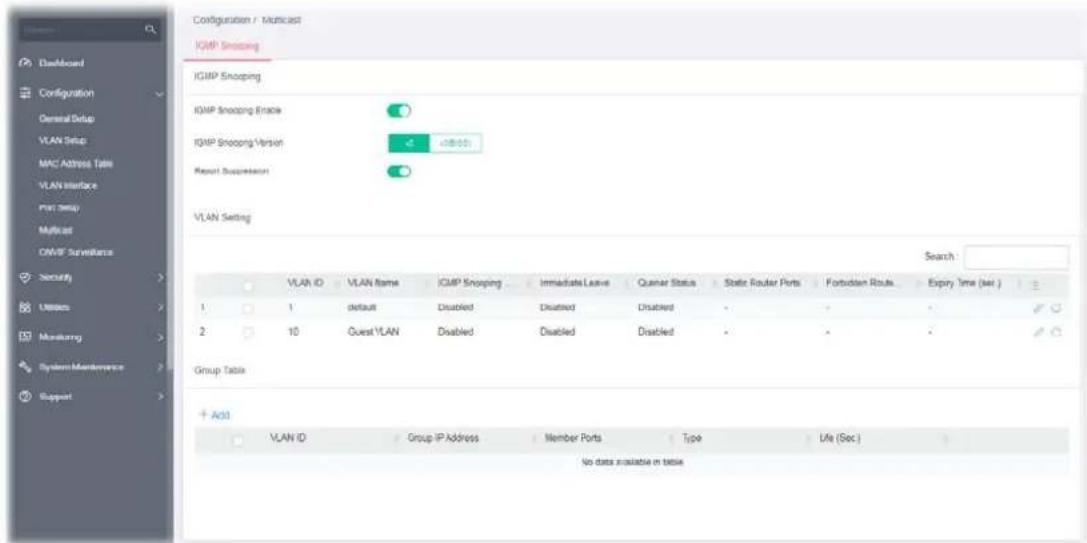
II-6-1 IGMP Snooping
IGMP snooping is the process of listening to Internet Group Management Protocol (IGMP) network traffic. The feature allows a network switch to listen in on the IGMP conversation between hosts and routers. By listening to these conversations the switch maintains a map of which links need which IP multicast streams. Multicasts may be filtered from the links which do not need them and thus controls which ports receive specific multicast traffic.
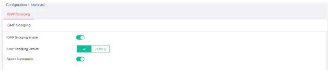
Available settings are explained as follows:
| Item | Description |
| IGMP Snooping Enable | Enable / Disable – Click the toggle to enable / disable this function.○ - means “Enable”.○ - means “Disable”. |
| IGMP Snooping Version | Set the IGMP snooping version.v2 - Only support process IGMP v2 packet.v3 - Support v3 basic and v2. |
| Report Suppression | It allows the switch to handle IGMP reports between router and host, suppressing bandwidth used by IGMP. Enable / Disable - Click the toggle to enable / disable this function. - means “Enable”.- means “Disable”. - means “Enable”.- means “Disable”. |
II-6-2 VLAN Setting
This page allows you to enable/disable IGMP function, select snooping version, and enable/disable snooping report suppression.

Available settings are explained as follows:
| Item | Description |
| VLAN ID Displays the VLAN ID number of the VLAN profile. | |
| VLAN Name Displays the name of the VLAN profile. | |
| IGMP Snooping Status Displays the status (Enabled/Disabled) of the IGMP function. | |
| Immediate Leave Displays the status (Enabled/Disabled) | |
| Querier Status Displays the status (Enabled/Disabled) of IGMP querier function. | |
| Static Router Ports Displays the LAN Port (GE/LAG) to send out query to remote host. | |
| Forbidden Router Ports | Displays the forbidden LAN Port (GE/LAG). |
| Expiry Time (sec.) | Displays the time before querier is considered no longer existed. |
| Click it to modify the IGMP setting. | |
| Clear current settings and return to factory default settings. | |
To modify settings for a port, click the link to open the setting page.
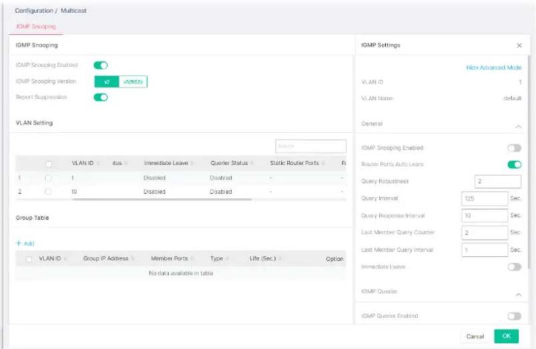
Available settings are explained as follows:
| Item | Description |
| IGMP Setting | |
| Show / Hide Advanced Mode | Click to display or hide the advanced settings. |
| VLAN ID Displays the VLAN ID number of the VLAN profile. | |
| VLAN Name Displays the name of the VLAN profile. | |
| General | IGMP Snooping Enable - Click the toggle to enable / disable this IGMP snooping function. - means "Enable".- means "Disable". - means "Enable".- means "Disable". |
| Below shows settings for Advanced Mode | |
| Router Ports Auto Learn | Click the toggle to enable / disable this function. Set the enabling status of IGMP router port learning. The server will learn router port by IGMP query. |
| Query Robustness | Set a number which allows tuning for the expected packet loss on a subnet. |
| Query Interval Set the interval of querier to send the general query. | |
| Query Response Interval | It specifies the maximum allowed time before sending a responding report in units of 1/10 second. |
| Last Member Query Counter | After querying for specified times (defined here) and still not receiving any response from the subscribed member, VigorSwitch will stop transmitting data to the related GE port(s). |
| Last Member Query Interval | The maximum time interval between counting each member query message with no responses from any subscribed member. |
| Immediate Leave | Leave the multicast group immediately on the port & VLAN where leave message is sent from, regardless there is still a subscribed member or not. Click Enable to enable Fastleave function. |
| IGMP Querier | IGMP Querier Enable - Click the toggle to enable / disable this function.In Advanced Mode,Querier Version - Set the IGMP snooping version.v2 - Only support process IGMP v2 packet.v3 - Support v3 basic and v2.For maximum compatibility, it is suggested to use querier version lower than IGMP snooping version, for there is possible network mixed with IGMP v2/v3 client and v2 query message is widely understandable for those clients. |
| IGMP Static Group | The IGMP static group is allowed to assign a VLAN/port as a specific IPv4 multicast member. Every IPv4 multicast stream that belongs to the specified group IP address will be forwarded to the specified port/VLAN member.Enable / Disable - Click the toggle to enable / disable this function.+Add - Click to create a new group.Group IP Address - Specify the IPv4 multicast address you wish to assign for the static group (defined in VLAN ID).Member Ports - Specify the port(s) that static group with given IPv4 multicast address shall include. |
After finishing this web page configuration, please click OK to save the settings.
II-6-3 Group Table
This page shows currently known and dynamically learned by IGMP snooping or shows the assigned IPv4 multicast address group in operation.
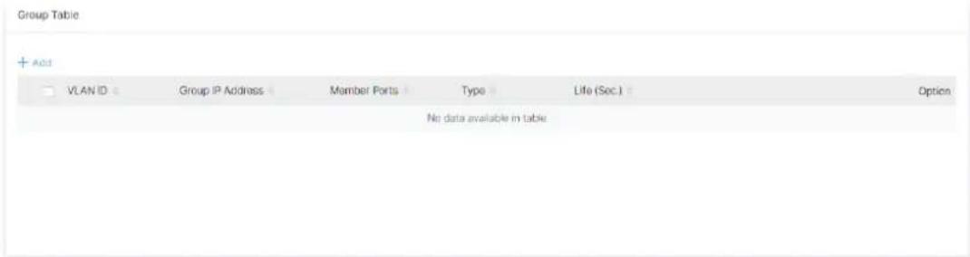
Available settings are explained as follows:
| Item | Description |
| +Add Click to create a new profile. | |
| VLAN ID Display the VLAN of this multicast group belongs to. | |
| Group IP Address | Display the multicast address of this multicast group. |
| Member Ports | Display the port(s) where subscribing member of this multicast group belongs to. |
| Type | Display if it is dynamically learned or statically assigned. |
| Life (Sec.) | Display the life time of this multicast member left if no membership report sent again. |
To add a new group, click the +Add link to open the setting page.
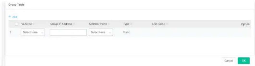
Available settings are explained as follows:
| Item | Description |
| VLAN ID Specify a VLAN profile as IGMP Static Group. | |
| Group IP Address | It is an identifier for the group member. Packets sent to such address will be transferred to all interfaces defined in Member Ports.Specify the IPv4 multicast address you wish to assign for the static group (defined in VLAN ID). |
| Member Ports Specify the port(s) that static group with given IPv4 multicast address shall include. | |
After finishing this web page configuration, please click OK to save the settings.
II-7 ONVIF Surveillance
ONVIF (Open Network Video Interface Forum), an International standard for current surveillance system industry, focuses on security products based on network IP address.
With this feature, VigorSwitch can:
● Integrate the ONVIF device and surveillance network
● Centralize management of IP video products
- View video images directly on VigorSwitch WUI
● Offer remote IP video products maintenance
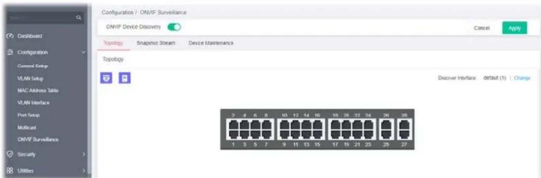
Switch the toggle to enable the ONVIF Device Discovery function. Then click Apply.
II-7-1 Topology
ONVIF devices can be centralized and managed remotely via VigorSwitch. With a hierarchy view, the administrator can manage several ONVIF devices and check abnormal traffic detected by the Vigor system.
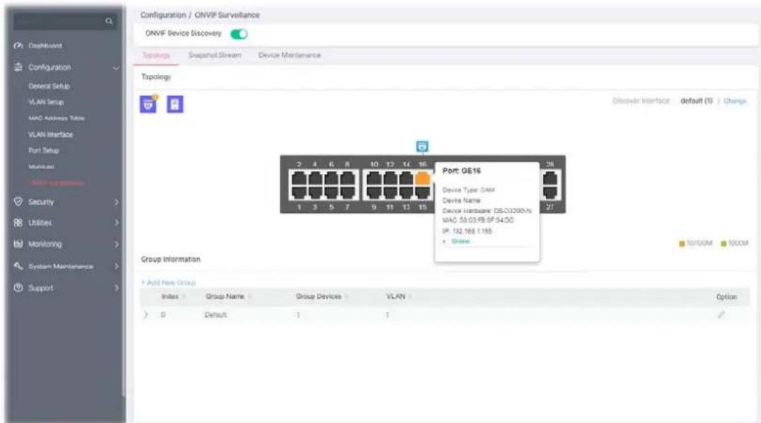
Available settings are explained as follows:
| Item | Description |
 | Camera - Displays the number of IP camera(s) connected to VigorSwitch. The panel sketch on the screen will display which LAN port that the IP camera connected.NVR - Displays the number of NVR device(s) connected to VigorSwitch. The panel sketch on the screen will display which LAN port that the NVR device connected. |
Change VigorSwitch will detect the ONVIF device based on the interface selected.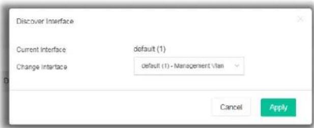 | |
| +Add New Group A group can contain one (IP camera or NVR, as group leader) to several devices (IP cameras as group devices).Click to create a new group for managing multiple devices. | |
| Index Displays the index number of the group profile. | |
| Group Name | Displays the name of the group profile. |
| Group Devices | Displays the number of the devices grouped under this profile. |
| VLAN | Displays the VLAN profile. |
| Option | - Click it to modify the group setting. |
To modify settings for a port, click the link to open the setting page.
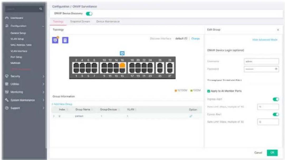
Available settings are explained as follows:
| Item | Description |
| Edit Group | |
| Show / Hide Advanced Mode | Click to display or hide the advanced settings. |
| ONVIF Device Login (optional) | |
| Username / Password | Enter a name / password as the default value.In the entire ONVIF Surveillance menu, VigorSwitch will input this value in advanced and retrieve data. System administrator can access the IP device in which the username and password are as same as the default values.However, you can also input another username/password manually if the IP device username/password is different from the one you enter in Default Username/Default Password. |
| Advanced Mode - Throughput Threshold Alert | |
| Apply to All Member Ports | Check the box to apply the throughput threshold setting to all member ports. |
| Ingress Alert Toggle the switch to enable the function. Set the ingress limit value.When the incoming traffic (packet) of the GE port reaches the limit, the Vigor System will send an alert email to the system administrator. Rate Limit - Enter the ingress rate as a threshold to send mail alert. | |
| Egress Alert Toggle the switch to enable the function. Rate Limit - Enter the egress rate as a threshold to send mail alert. | |
After finishing this web page configuration, please click OK to save the settings.
To create a new group, click the +Add New Group link to open the setting page.
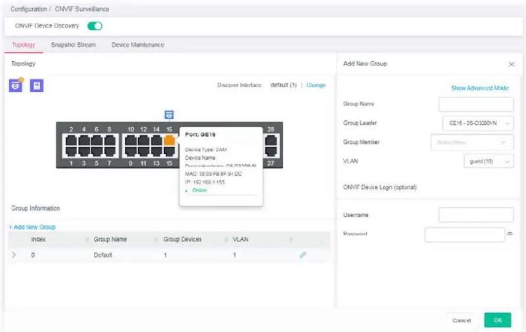
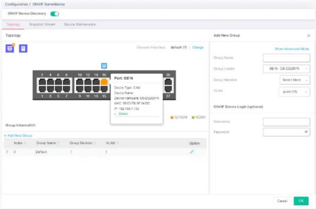
Available settings are explained as follows:
| Item | Description |
| Add New Group | |
| Show / Hide Advanced Mode | Click to display or hide the advanced settings. |
| Group Name Enter the name of a group. | |
| Group Leader The system will detect the NVR or IP cameras, and list them on the field of NVR or Group Leader. | |
| Group Member This field lists all devices (IP cameras) not included by other group.Select one IP device to multiple devices or select all the devices for managed by this group. | |
| ONVIF Device Login (optional) | |
| Username / Password | Enter a name / password as the default value.In the entire ONVIF Surveillance menu, VigorSwitch will input this value in advanced and retrieve data. System administrator can access the IP device in which the username and password are as same as the default values.However, you can also input another username/password manually if the IP device username/password is different from the one you enter in Default Username/Default Password. |
| Throughput Threshold Alert | |
| Apply to All Member Ports | Check the box to apply the throughput threshold setting to all member ports. |
| Ingress Alert Toggle the switch to enable the function. Set the ingress limit value.When the incoming traffic (packet) of the GE port reaches the limit, the Vigor System will send an alert email to the system administrator.Rate Limit - Enter the ingress rate as a threshold to send mail alert. | |
Egress Alert Toggle the switch to enable the function. Set the egress limit value.
When the incoming traffic (packet) of the GE port reaches the limit, the Vigor System will send an alert email to the system administrator.
Rate Limit - Enter the ingress rate as a threshold to send mail alert.
After finishing this web page configuration, please click OK to save the settings.
II-7-2 Snapshot Stream
This page can offer a real-time video of specified IP camera for monitoring and control environments.
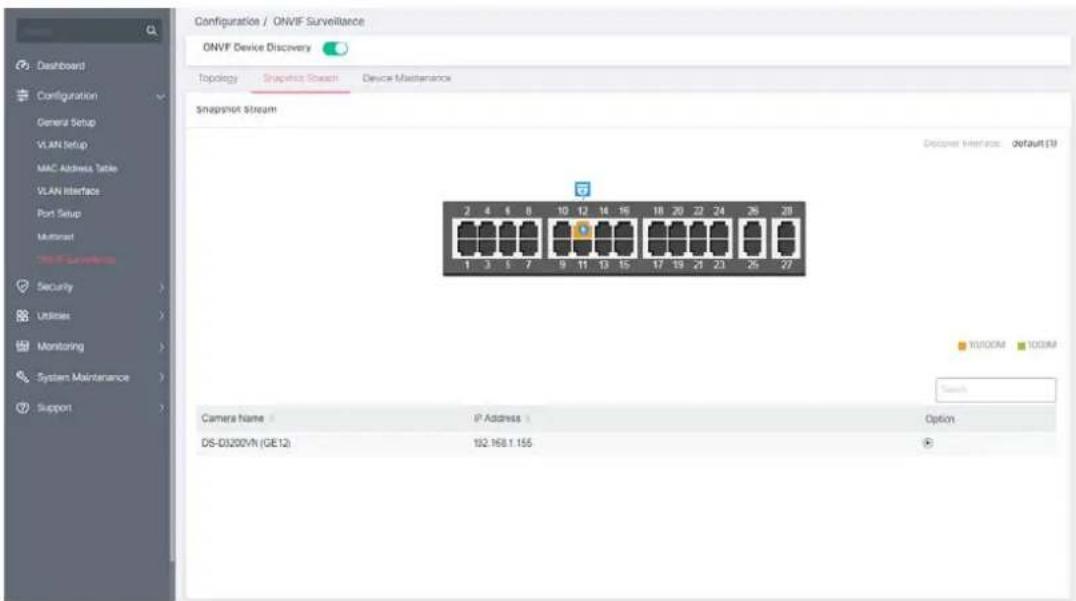
Available settings are explained as follows:
| Item | Description |
| Snapshot Stream | |
| Camera Name Displays the device name of the IP camera. | |
| IP Address Displays the IP address of the IP camera. | |
After authenticated with correct username and password, the image of the specified IP camera (supported by VigorSwitch) will be shown immediately.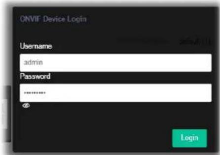 | |
| Username / Password - The default username/password will be input if it is configured on the Topology page. However, if the default input is not the correct username/password, enter the correct one of the IP camera instead. | |
Login - Click it to authenticate the username and password for the specified IP camera.
A pop-up window (Video Preview) appears to display a live image on the screen.
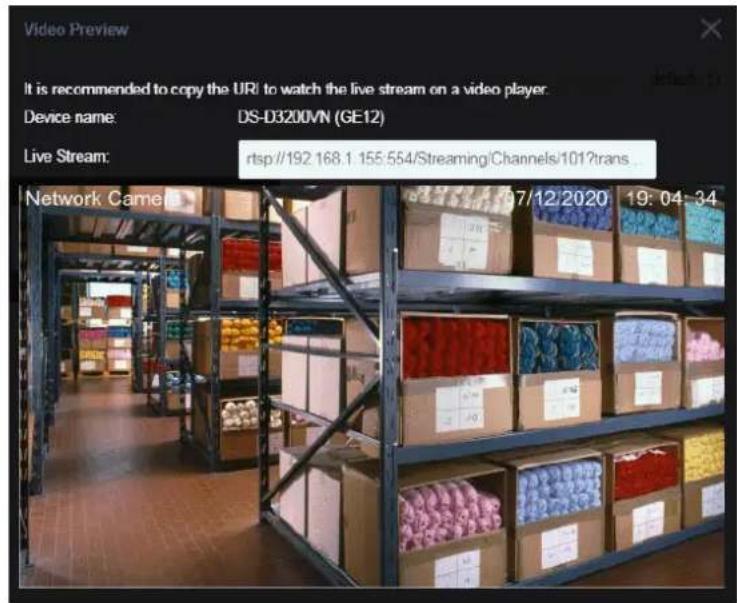
II-7-3 Device Maintenance
The system administrator can remotely configure time setting, security settings and reboot the devices (IP cameras or NVRs) managed by Vigor switch.
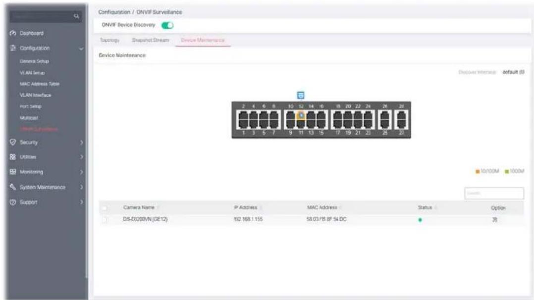
Available settings are explained as follows:
| Item | Description |
| Device Maintenance | |
| Camera Name Displays the device name of the IP camera. | |
| IP Address Displays the IP address of the IP camera. | |
| MAC Address Displays the MAC address of the IP camera. | |
| Status | Displays the status (enabled or disabled) of the IP camera. |
| Option | - Click to configure detailed settings for the selected device. |

Click
to configure detailed settings. First you have to login the ONVIF device.
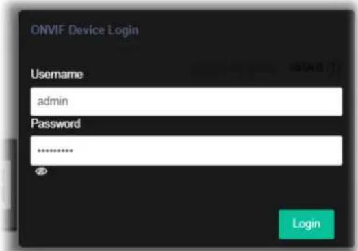
After entering the correct username and password of the device, the detailed settings page will be shown as follows:
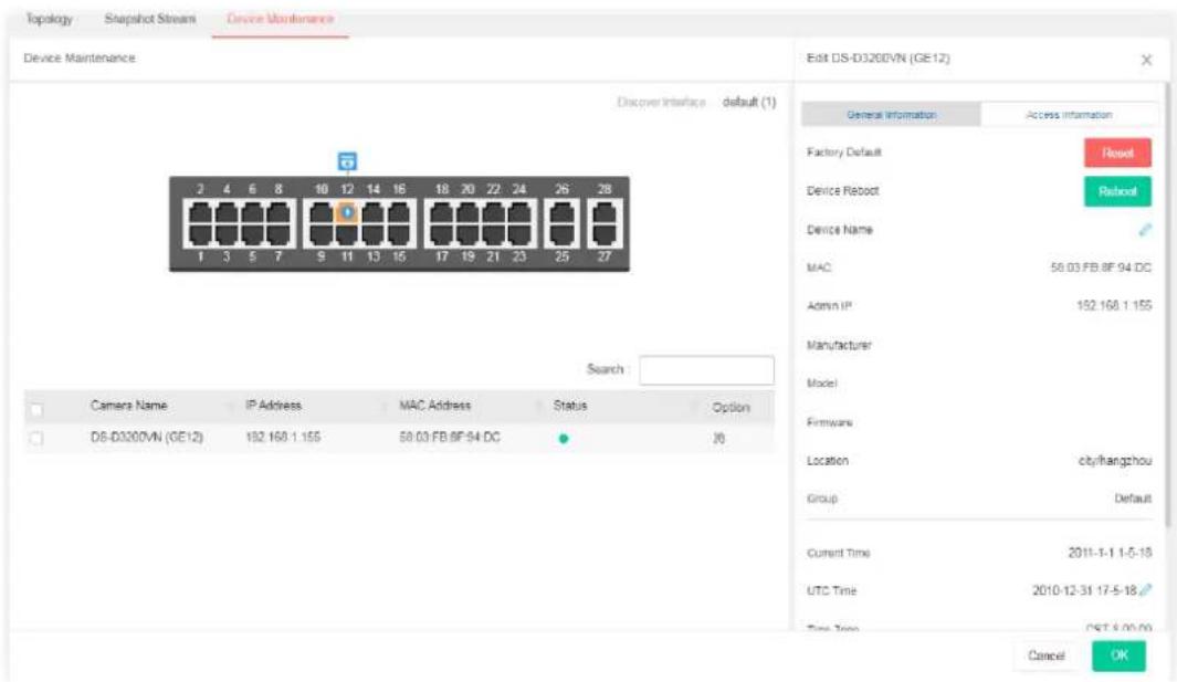
Available settings are explained as follows:
| Item | Description |
| General Information | |
| Factory Default Reset - Reset the factory default to the IP device. | |
| Device Reboot Reboot - Reboot the IP device immediately. | |
| Device Name | Click to modify the name of the device. |
| MAC Displays the MAC address of the device. | |
| Admin IP Displays the IP address of the device. | |
| Manufacturer Displays the manufacturer of the device. | |
| Model Displays the model name of the device. | |
| Firmware Displays the firmware version used by the device. | |
| Location Displays the location of the device. | |
| Group Displays the name of the group. | |
| Current Time Displays the time set for the device. | |
| UTC Time | Display the time and date information related to the selected device. |
| Time Zone Displays the time zone based on the location of the device. | |
| Daylight Saving | Displays the status (enabled/disabled) of the daylight saving function. |
Auto Device Check Click the toggle to enable / disable this function. - means "Enable". - means "Enable". - means "Disable".Mail Alert - Click the toggle to enable / disable this function. When the device is offline, Vigor system will send an alert mail to notify the recipient.With Snapshot - If enabled, the switch will try to get snapshot from the device per half hour. Before using this feature, set the group authentication information when adding group or configure Default Username/Password in the Topology page first.When the device is offline, no action will be performed. - means "Disable".Mail Alert - Click the toggle to enable / disable this function. When the device is offline, Vigor system will send an alert mail to notify the recipient.With Snapshot - If enabled, the switch will try to get snapshot from the device per half hour. Before using this feature, set the group authentication information when adding group or configure Default Username/Password in the Topology page first.When the device is offline, no action will be performed. | |
| Access Information | |
| Mode Change the connection mode for this device. | |
| Static - When it is selected, you have to enter value for network setting manually for the IP device.IP Address - Enter an IPv4 address for the IP devicePrefix Length - Specify the subnet mask for the IP address.Gateway - Enter the IPv4 address for the gateway.DNS Server1/2 - Enter the IP address for primary / secondary DNS server.DHCP - When it is selected, the IP device will be assigned with the settings by the network's DHCP server automatically to access the Internet.Hostname - Displays the hostname of the DHCP server. | |
| Zero Configuration Click the toggle to enable / disable this function. | |
| Enable - The network settings for the IP device will be configured automatically.Disable - The network settings for the IP device must be configured manually. | |
| HTTP Port Click the toggle to enable / disable this function. | |
| Enable - Click it to enable the HTTP port configuration and enter a port value if required.Disable - Disable the HTTP port configuration. | |
| HTTPS Port | Click the toggle to enable / disable this function.Enable - Click it to enable the HTTPS port configuration and enter aport value if required. Disable - Disable the HTTPS port configuration. |
| RTSP Port Click the toggle to enable / disable this function. Enable - Click it to enable the RTSP port configuration and enter a port value if required. Disable - Disable the RTSP port configuration. | |
This page is left blank.
Chapter III Security

natural_image
Abstract shield icon with a red keyhole symbol inside (no text or numbers)III-1 Access Control List
An Access Control List (ACL) is a sequential list of permit or deny conditions that apply to IP addresses, MAC addresses, or other more specific criteria. This switch tests ingress packets against the conditions in an ACL one by one. A packet will be accepted as soon as it matches a permit rule, or dropped as soon as it matches a deny rule. If no rules match, the frame is accepted.
Users can create the Access Control List (ACL) based on Layer 2 filtering, the MAC layer, Layer 2 to Layer 4 filtering, the IPv4, and Layer 2 to Layer 4 filtering, the IPv6. The ACL is composed by many Access Control Element (ACE) rules. You can create a new ACL here; then add multiple ACEs.
You may provide filtering/matching criteria for one or more packet characteristics (such as Source/Destination MAC, Ethertype, VLAN, 802.1p) for this ACE to identify the packet.
III-1-1 Access Control List
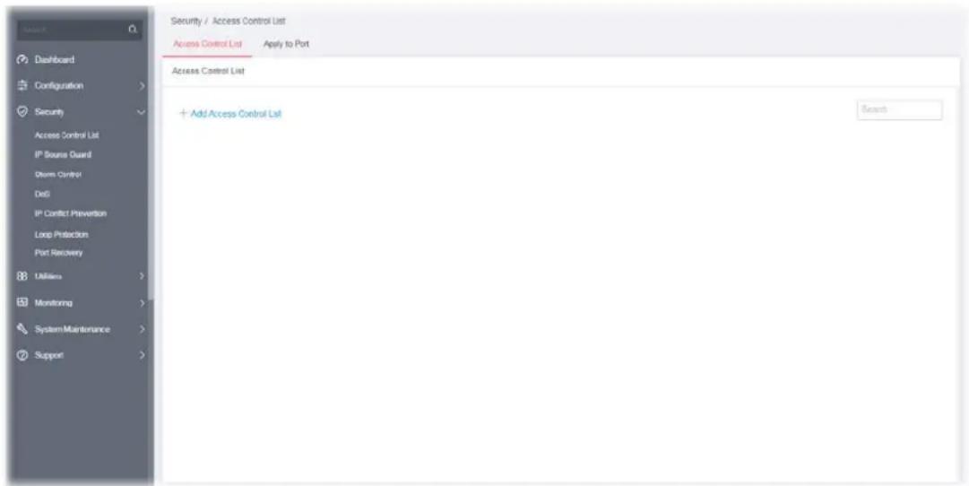
List Type - MAC
To create a new access control list, click the +Add Access Control List link to open the setting page.
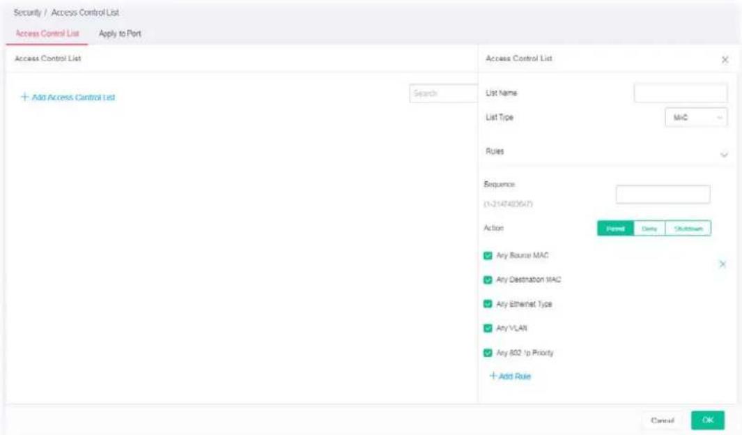
Available settings are explained as follows:
| Item | Description |
| Access Control List | |
| List Name Enter a name for creating a new ACL profile. | |
| List Type Specify the filtering type (MAC/IPv4/IPv6). | |
| Rules | |
| Sequence | Assign a sequence number to this ACE. The sequence is used to identify which one of ACEs in an ACL is firstly used to match ingress packets. The switch port bound with an ACL use the contained ACE rules, start with the one with lower sequence number to match the packet first. |
| Action Select the action applied to the packet matched this ACE. Permit or deny the packets into switch core, or shutdown the port for stopping further transmission.PermitDenyShutdown | |
| Any Source MAC If disabled, please enter IP address with the subnet mask.Any Source MAC | |
| Any Destination MAC If disabled, please enter IP address with the subnet mask. | |
| Any Ethernet Type | Specify Ethernet type for filtering. Select Any Ethernet.Or, enter the value with the format of "0x600 ~ 0xFFFF".Any EthernetType(0x600-0xFFFF) |
| Any VLAN | Specify VLAN profile for filtering. Select Any VLAN.Or, enter a VLAN number. The packets coming from the VLAN specified here will be filtered by Vigor device.□ Any VLAN (1-4094) |
| Any 802.1p Priority | Specify the 802.1p priority value for filtering. Select Any 802.1p Priority.Or, enter a number from 0 to 7.□ Any 802.1p Priority (0-7) / |
| +Add Rule Click it to create a new ACE rule.Each ACL profile can be added with 8 ACE rules. | |
After finishing this web page configuration, please click OK to save the settings.
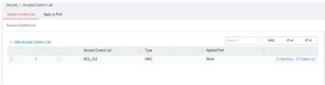
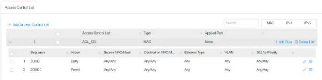
List Type - IPv4
To create a new access control list, click the +Add Access Control List link to open the setting page.
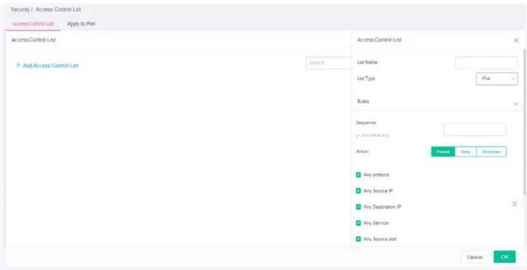
Available settings are explained as follows:
| Item | Description |
| Access Control List | |
| List Name Enter a name for creating a new ACL profile. | |
| List Type Specify the filtering type (IPv4). | |
| Rules | |
| Sequence | Assign a sequence number to this ACE. The sequence is used to identify which one of ACEs in an ACL is firstly used to match ingress packets. The switch port bound with an ACL use the contained ACE rules, start with the one with lower sequence number to match the packet first. |
| Action Select the action applied to the packet matched this ACE. Permit or deny the packets into switch core, or shutdown the port for stopping further transmission.·Permit·Deny·Shutdown | |
| Any Protocol Specify the protocol for filtering.Any Protocol - Default setting. All packets will be filtered.Self-Define - Enter a number (0 - 255) to specify a protocol. For example, 1 means “Internet Control Message”; 6 means “Transmission Control”.ICMP, IP in IP,... - Choose one of the protocols (e.g., ICMP, IP In IP, TCP, EGP, IGP...) from the drop down list. Packets passing through the selected protocol will be filtered. | |
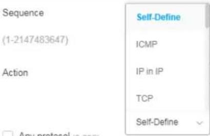 | ||
 | ||
Any Source IP Specify the source IPv4 address for filtering.Any Source IP - Default setting. All packets will be filtered.Select Any Source IP. Or, enter the IP address to filter the packets coming from that address.  | ||
Any Destination IP Specify the destination IPv4 address for filtering.Any Destination IP - Default setting. All packets will be filtered.Select Any Destination IP. Or, enter the IP address to filter the packets coming from that address.  | ||
Any Service Any Service - Default setting. All packets will be filtered.DSCP - All IP traffic is mapped to queues based on the DSCP field in the IP header. If traffic is not IP traffic, it is mapped to the lowest priority queue.IP Precedence - All IP traffic is mapped to queues based on the IP Precedence field in the IP header. If traffic is not IP traffic, it is mapped to the lowest priority queue. 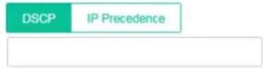 | ||
Any Source Port Specify the source port number for filtering the packets.Any Source Port - Default setting. All packets will be filtered.Select Any Source Port. Or, enter the port number.Single - Only the packets passing through the number defined here will be filtered. Range - Only the packets passing through the port range defined Range - Only the packets passing through the port range defined | ||
here will be filtered. | |
| Any Destination Port | Specify the destination port number for filtering the packets.Any Destination Port- Default setting. All packets will be filtered.Select Any Destination Port. Or, enter the port number.Single- Only the packets passing through the number defined here will be filtered. Range- Only the packets passing through the port range defined here will be filtered. Range- Only the packets passing through the port range defined here will be filtered. |
| Any ICMP Type | Any ICMP Type- Default setting. All packets will be filtered.Echo Reply, Destination Unreachable.... - Choose one of the type (e.g., Destination Unreachable, Echo Reply, MLD Query....) from the drop down list.Self-Define- Specify a type number (0 - 255) for ICMP code. For example, 0 means “Echo Reply”; 254 means “RFC3692-style Experiment 2”.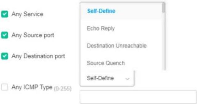 |
| Any ICMP Code | ach ICMP type can be defined with different codes. For example, if you define ICMP Type as “3”, then the available codes for Type 3 will be 0-15.Any ICMP Code- Default setting. All packets will be filtered.Select Any ICMP Code. Or, enter 0 to 255 based on the ICMP type specified. |
| +Add Rule | Click it to create a new ACE rule.Each ACL profile can be added with 8 ACE rules. |
List Type - IPv6
To create a new access control list, click the +Add Access Control List link to open the setting page.
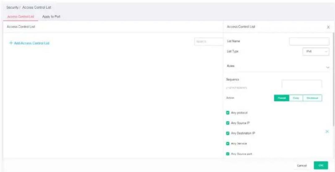
Available settings are explained as follows:
| Item | Description |
| Access Control List | |
| List Name Enter a name for creating a new ACL profile. | |
| List Type Specify the filtering type (IPv6). | |
| Rules | |
| Sequence | Assign a sequence number to this ACE. The sequence is used to identify which one of ACEs in an ACL is firstly used to match ingress packets. The switch port bound with an ACL use the contained ACE rules, start with the one with lower sequence number to match the packet first. |
| Action Select the action applied to the packet matched this ACE. Permit or deny the packets into switch core, or shutdown the port for stopping further transmission.·Permit·Deny·Shutdown | |
| Any Protocol Specify the protocol for filtering.Any Protocol - Default setting. All packets will be filtered.Self-Define - Enter a number (0 - 255) to specify a protocol. For example, 1 means “Internet Control Message”; 6 means “Transmission Control”.ICMP, IP in IP,... - Choose one of the protocol (e.g., ICMP, TCP, EGP...) from the drop down list. Packets passing through the selected protocol will be filtered. | |
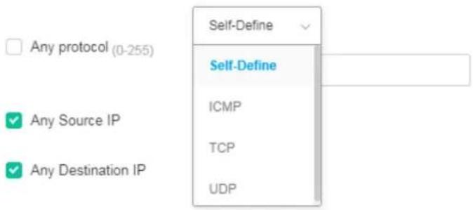 | |
Any Source IP Specify the source IPv6 address for filtering.Any Source IP - Default setting. All packets will be filtered.Select Any Source IP. Or, enter the IP address to filter the packets coming from that address.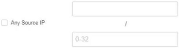 | |
Any Destination IP Specify the destination IPv6 address for filtering.Any Destination IP - Default setting. All packets will be filtered.Select Any Destination IP. Or, enter the IP address to filter the packets coming from that address.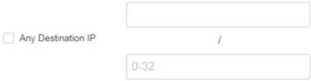 | |
Any Service Any Service - Default setting. All packets will be filtered.DSCP - All IP traffic is mapped to queues based on the DSCP field in the IP header. If traffic is not IP traffic, it is mapped to the lowest priority queue.IP Precedence - All IP traffic is mapped to queues based on the IP Precedence field in the IP header. If traffic is not IP traffic, it is mapped to the lowest priority queue. | |
Any Source Port Specify the source port number for filtering the packets.Any Source Port - Default setting. All packets will be filtered.Select Any Source Port. Or, enter the port number.Single - Only the packets passing through the number defined here will be filtered. Range - Only the packets passing through the port range defined Range - Only the packets passing through the port range defined | |
here will be filtered. | |
| Any Destination Port | Specify the destination port number for filtering the packets.Any Destination Port- Default setting. All packets will be filtered.Select Any Destination Port. Or, enter the port number.Single- Only the packets passing through the number defined here will be filtered. Range- Only the packets passing through the port range defined here will be filtered. Range- Only the packets passing through the port range defined here will be filtered. |
| Any ICMP Type | Any ICMP Type- Default setting. All packets will be filtered.Echo Reply, Destination Unreachable.... - Choose one of the type (e.g., Destination Unreachable, Echo Reply, MLD Query....) from the drop down list.Self-Define- Specify a type number (0 - 255) for ICMP code. For example, 0 means “Echo Reply”; 254 means “RFC3692-style Experiment 2”.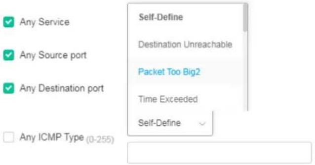 |
| Any ICMP Code | ach ICMP type can be defined with different codes. For example, if you define ICMP Type as “3”, then the available codes for Type 3 will be 0-15.Any ICMP Code- Default setting. All packets will be filtered.Select Any ICMP Code. Or, enter 0 to 255 based on the ICMP type specified. |
| +Add Rule | Click it to create a new ACE rule.Each ACL profile can be added with 8 ACE rules. |
III-1-2 Apply to Port
It allows you to bind Access Control Lists created in previous section to an interface (physical port or aggregation).
A physical port can only be bound with one of the IPv4 and IPv6 ACLs, not both.
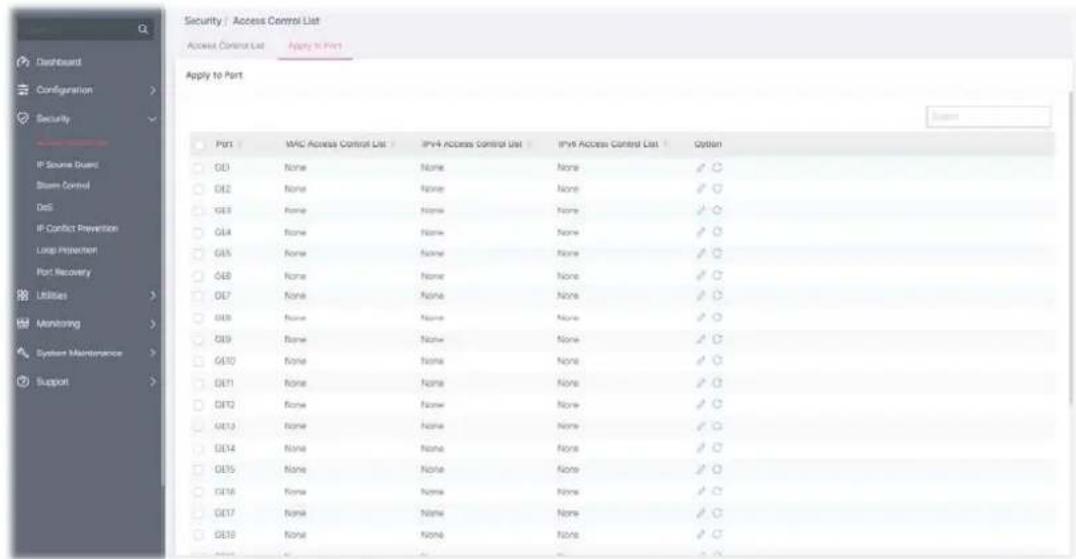
Available settings are explained as follows:
| Item | Description |
| Port Select the port profiles (GE1 to GE28) for binding ACL. | |
| MAC Access Control List | Displays the ACL (MAC) to be bound on this interface (port), so the switch may filter packets by using it. |
| IPv4 Access Control List | Displays the ACL (IPv4) to be bound on this interface (port), so the switch may filter packets by using it. |
| IPv6 Access Control List | Displays the ACL (IPv6) to be bound on this interface (port), so the switch may filter packets by using it. |
| Option | - Click it to modify the port setting.- Clear current settings and return to factory default settings. |
To modify settings for a port, click the link to open the setting page.
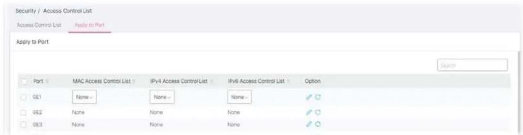
Available settings are explained as follows:
| Item | Description |
| MAC Access Control List | Select an ACL (MAC) to be bound on this interface (port). |
| IPv4 Access Control List | Select an ACL (IPv4) to be bound on this interface (port). |
| IPv6 Access Control List | Select an ACL (IPv6) to be bound on this interface (port). |
By using the source IP address filtering function, IP source guard can prevent a malicious host from feigning a legal host with its IP address and performing malicious attack.
IP source guard is a port-based feature. Therefore, it is necessary to configure detailed settings for each GE/LAG port interface separately.
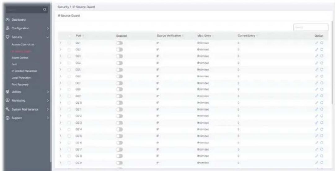
Available parameters are explained as follows:
| Item | Description |
| Port | Displays the port profile (GE1 to GE28). Check the box to the left side to select the port profile. |
Enabled Click the toggle to enable / disable this profile. | - means "Enable".- means "Disable". |
| Source Verification Displays the type of source IP for the packet coming from. | |
| Max. Entry | Displays the total number (0~50) of accessible entries allowed for this port. |
| Current Entry Displays the number of accessible entries of this port. | |
| Option | - Click it to modify the IP Source Guard setting of the selected port.- Clear current settings and return to factory default settings. |
To modify settings for a port, click the

link to open the setting page.
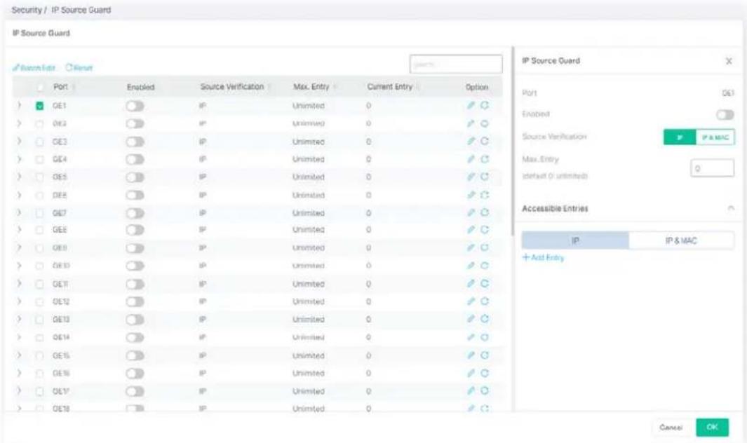
Available settings are explained as follows:
| Item | Description |
| IP Source Guard | |
| Port | Displays the port profile (GE1 to GE28). |
| Enable | Click the toggle to enable / disable this function. - means "Enable". - means "Enable". - means "Disable". - means "Disable". |
| Source Verification | Specify the type of source IP for the packet coming from.IP - Only the packet with specified IP address will be verified.IP & MAC - Only the packet with specified IP address and MAC address will be verified. |
| Max. Entry | Define the total number (0~50) of accessible entries allowed for this port. The default is 0 (no limit). |
| Accessible Entries | Define the entry for applying the IP source guard function.IP - Select this type to enter an IPv4 address and set a VLAN ID.IP & MAC - Select this type to enter an IP address, MAC address and IPv4 address.+Add Entry - Click to display blank entry boxes for configuring a new IP address, MAC address, and VLAN ID. |
After finishing this web page configuration, please click OK to save the settings.
Storm Control helps to suppress possible broadcast, unknown multicast or unknown unicast storm by applying a rate limit on those packets.
This page allows a user to configure general settings for Storm Control. In addition, it is used to configure port settings for Storm Control. The configuration result for each port will be displayed on the table listed on the lower side of this web page.
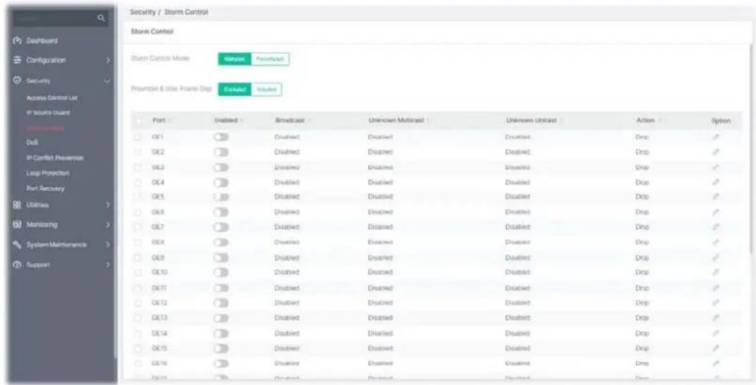
Available settings are explained as follows:
| Item | Description |
| Storm Control Mode | Select the mode of storm control.Kbits/sec- Storm control rate will be calculated by octet-based.Packet/sec- Storm control rate will be calculated by packet-based. |
| Preamble & Inter Frame Gap | Select the rate calculation with/without preamble & IFG (20 bytes).Excluded- Exclude preamble & IFG (20 bytes) when count ingress storm control rate.Included- Include preamble & IFG (20 bytes) when count ingress storm control rate. |
| Port Enable/disable the port (GE1 to GE28) profiles. | |
| Enabled | Click the toggle to enable / disable this profile. - means “Enable”. - means “Enable”. - means “Disable”. - means “Disable”. |
| Broadcast Displays the storm control rate limited for broadcast. | |
| Unknown Multicast Displays the storm control rate limited for unknown multicast. | |
| Unknown Unicast Displays the storm control rate limited for unknown unicast. | |
| Action Displays the action performed. | |
| Click to modify the storm control settings of the selected port. | |
To modify settings for a port, click the link to open the setting page.
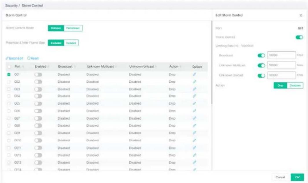
Available settings are explained as follows:
| Item | Description |
| Edit Storm Control | |
| Port Display the port profile selected to be modified. | |
| Storm Control | Click the toggle to enable / disable this function.- means “Enable”.- means “Disable”. |
| Limiting Rate | Broadcast - Specify the storm control rate for Broadcast packet. Value of storm control rate, Unit: Kbps (Kbits per-second). The range is from 16 to 1000000.Unknown Multicast - Specify the storm control rate for unknown multicast packet. Value of storm control rate, Unit: Kbps (Kbits per-second). The range is from 16 to 1000000.Unknown Unicast - Specify the storm control rate for unknown multicast packet. Value of storm control rate, Unit: Kbps (Kbits per-second). The range is from 16 to 1000000. |
| Action | Select the state of setting.Drop - Packets exceed storm control rate will be dropped.Shutdown - Port exceeds storm control rate will be shutdown. |
After finishing this web page configuration, please click OK to save the settings.
A Denial of Service (DoS) attack is a hacker attempt to make a device unavailable to its users. DoS attacks saturate the device with external communication requests, so that it cannot respond to legitimate traffic. These attacks usually lead to a device CPU overload.
The DoS protection feature is a set of predefined rules that protect the network from malicious attacks. The DoS Security Suite Setting enables activating the security suite.
III-4-1 Properties
This page allows a user to configure DoS setting to enable/disable DoS function for global setting.
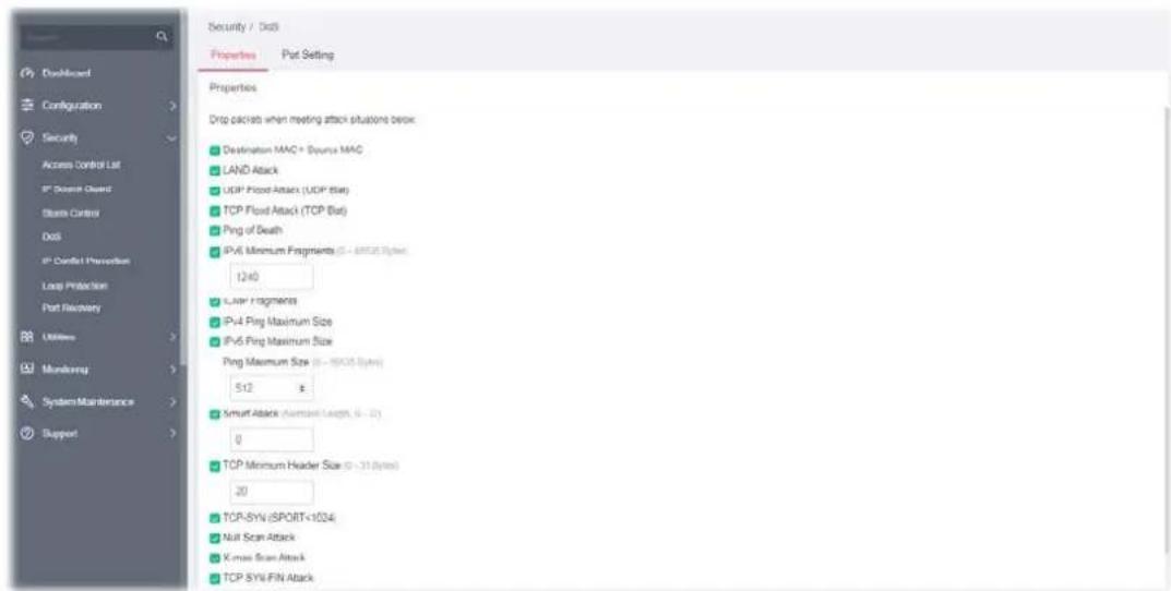
Available settings are explained as follows:
| Item | Description |
| Destination MAC=Source MAC | Drops the packets if the destination MAC address is equal to the source MAC address.Check/unchecked the box to enable/disable the function. |
| LAND Attack Drops the packets if the source IP address is equal to the destination IP address.Check/unchecked the box to enable/disable the function. | |
| UDP Flood Attack (UDP Blat) | Drops the packets if the UDP source port equals to the UDP destination port.Check/unchecked the box to enable/disable the function. |
| TCP Flood Attack (TCP Blat) | Drops the packages if the TCP source port is equal to the TCP destination port.Check/unchecked the box to enable/disable the function. |
| Ping to Death | Avoids ping of death attack. Ping packets that length are larger than 65535 bytes.Check/unchecked the box to enable/disable the function. |
| IPv6 Minimum Fragments | Checks the minimum size of IPv6 fragments, and drop the packets smaller than the minimum size. The valid range is from 0 to 65535 bytes, and default value is 1240 bytes.Check/unchecked the box to enable/disable the function. |
| ICMP Fragments Drops the fragmented ICMP packets.Check/unchecked the box to enable/disable the function. | |
| IPv4 Ping Maximum Size | Determines the IPv4 PING packet with the length.Check/unchecked the box to enable/disable the function. |
| IPv6 Ping Maximum Size | Determines the IPv6 PING packet with the length.Check/unchecked the box to enable/disable the function.Ping Maximum Size - Determine the IPv4/IPv6 PING packet with the length. Specify the maximum size of the ICMPv4/ICMPv6 ping packets. The valid range is from 0 to 65535 bytes, and the default value is 512 bytes. |
| Smurf Attack | Avoids smurf attack. The length range of the netmask is from 0 to 323 bytes, and default length is 0 byte.Check/unchecked the box to enable/disable the function. |
| TCP Minimum Header Size | Checks the minimum TCP header and drops the TCP packets with the header smaller than the minimum size. The length range is from 0 to 31 bytes, and default length is 20 bytes.Check/unchecked the box to enable/disable the function. |
| TCP-SYN (SPORT<1024) Drops SYN packets with sport less than 1024.Check/unchecked the box to enable/disable the function. | |
| Null Scan Attack Drops the packets with NULL scan.Check/unchecked the box to enable/disable the function. | |
| X-mas Scan Attack Drops the packets if the sequence number is zero, and the FIN, URG and PSH bits are set.Check/unchecked the box to enable/disable the function. | |
| TCP SYN-FIN Attack Drops the packets with SYN and FIN bits set.Check/unchecked the box to enable/disable the function. | |
| TCP SYN-RST Attack Drops the packets with SYN and RST bits set.Check/unchecked the box to enable/disable the function. | |
| TCP Fragment (Offset=1) Drops the fragmented ICMP packets.Check/unchecked the box to enable/disable the function. | |
After finishing this web page configuration, please click OK to save the settings.
III-4-2 Port Setting
This page allows a user to configure and display the state of DoS protection for interfaces. The configuration result for each port will be displayed on the table listed on the lower side of this web page.
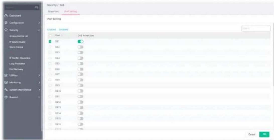
Available settings are explained as follows:
| Item | Description |
| Port | Displays the port profile (GE1 to GE28). Check the box to the left side to select the port profile. |
| DoS Protection | Click the toggle to enable / disable the function of DoS Protection. - means "Enable". - means "Enable". - means "Disable". - means "Disable". |
After finishing this web page configuration, please click OK to save the settings.
III-5 IP Conflict Prevention
A user can configure IP addresses for network devices manually. However, it might result in conflict between different devices due to using the same IP address, and cause the devices not working correctly.
IP Conflict Prevention allows you to prevent IP conflict by binding the port with the specified IP address.
Prevention Level: Off
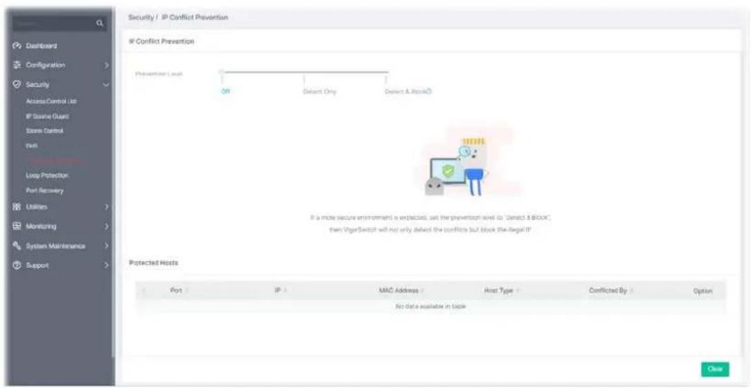
Prevention Level: Detect & Block
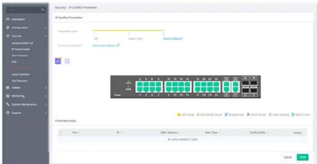
Available settings are explained as follows:
| Item | Description |
| IP Conflict Prevention | |
Prevention Level Off - The function of IP conflict prevention is disabled.
Detect Only - VigorSwitch will detect the host but no further action executed.
Detect & Block - VigorSwitch will detect the host and block the host if it meets the configuration on this page.
Prevention Setup
Quick Setup Wizard - It is available only when Detect & Block is selected as Prevention Level. The system will guide to bind server port with an IP address step by step.
Step 1: Choose a server port. Click Next.
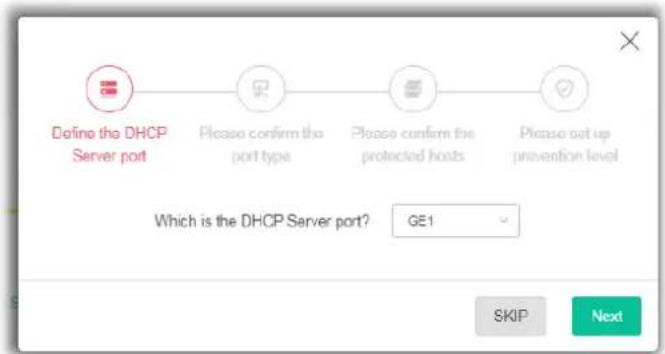
flowchart
graph LR
    A["Define the DHCP Server port"] --> B["Please confirm the port type"]
    B --> C["Please confirm the protected hosts"]
    C --> D["Please set up prevention level"]
Step 2: Confirm the port type. Click Next.
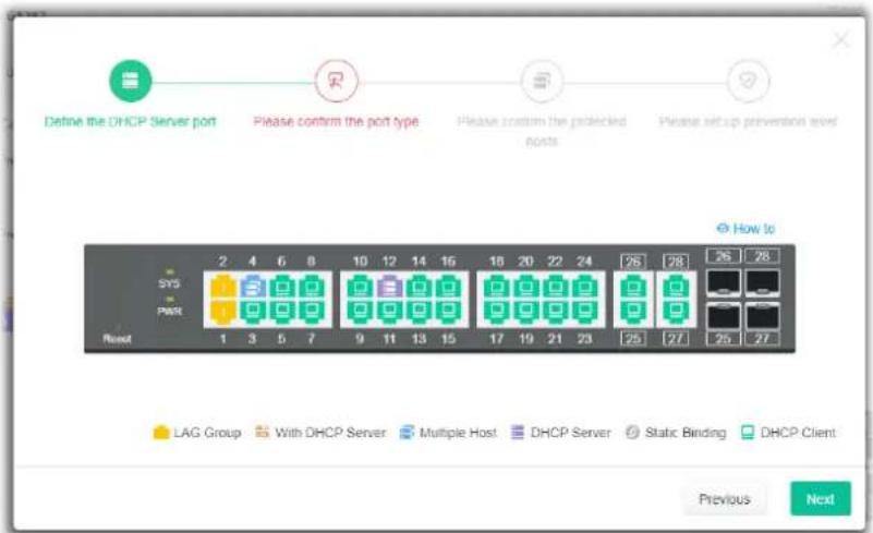
flowchart
graph TD
    A["Define the DHCP Server port"] --> B["Please confirm the port type"]
    B --> C["Please confirm the port type"]
    C --> D["Please set up prevention level"]
    D --> E["How to"]
    E --> F["2 4 6 8 10 12 14 16 18 20 22 24 26 28"]
    F --> G["SYS"]
    F --> H["PMS"]
    G --> I["1 3 5 7 9 11 13 15 17 19 21 23 25 27"]
    H --> J["Previous"]
    H --> K["Next"]
Step 3: Wait for the network detection.

flowchart
graph LR
    A["😊"] --> B["😊"]
    B --> C["..."]
    C --> D["..."]
    style A fill:#fff,stroke:#000
    style B fill:#fff,stroke:#000
    style C fill:#fff,stroke:#000
    style D fill:#fff,stroke:#000
    note bottom "Network Detecting..."
Step 4: Confirm / modify the protected host. Click Next.
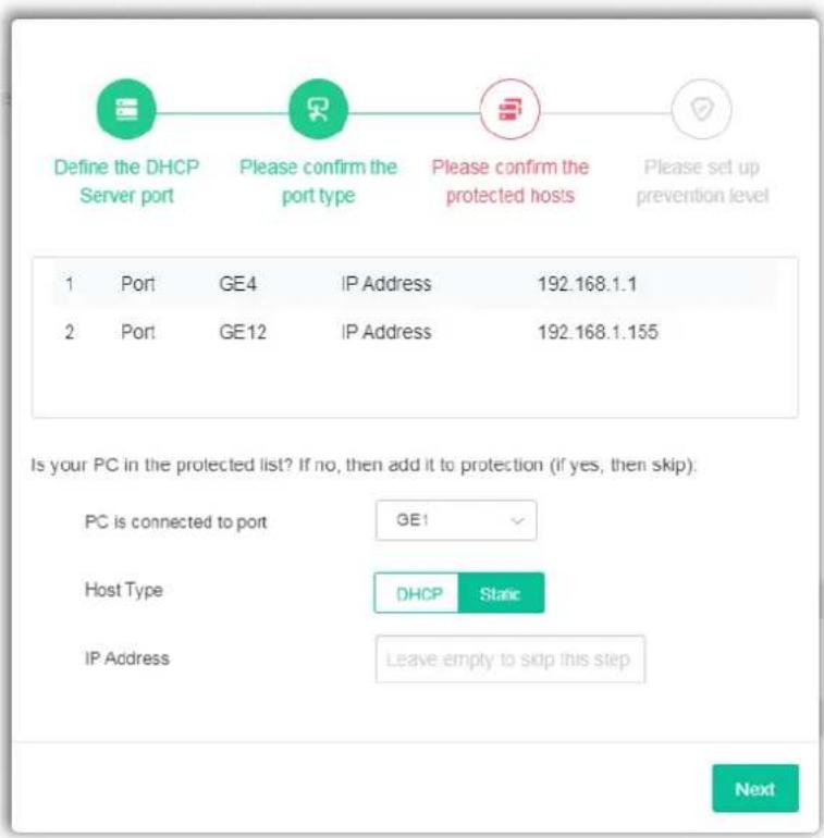
Step 5: Set up the prevention level. Click Next.
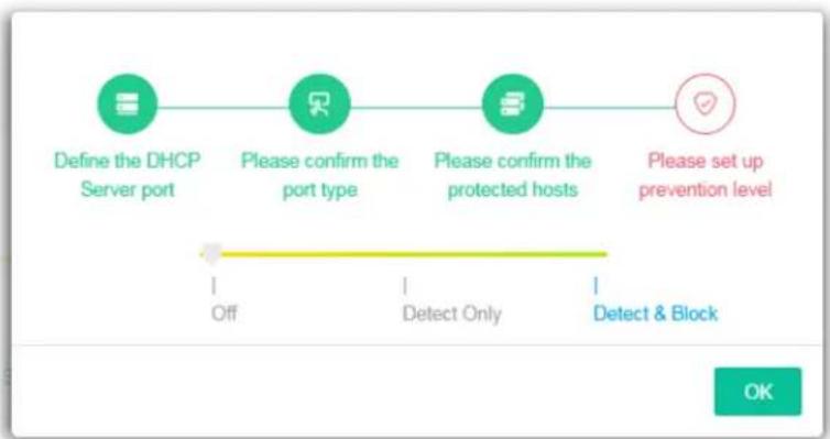
flowchart
graph LR
    A["Define the DHCP Server port"] --> B["Please confirm the port type"]
    B --> C["Please confirm the protected hosts"]
    C --> D["Please set up prevention level"]
    D --> E["Detect Only"]
    E --> F["Detect & Block"]
After clicking OK, the IP address specified for the GE port will be unavailable for other network devices.
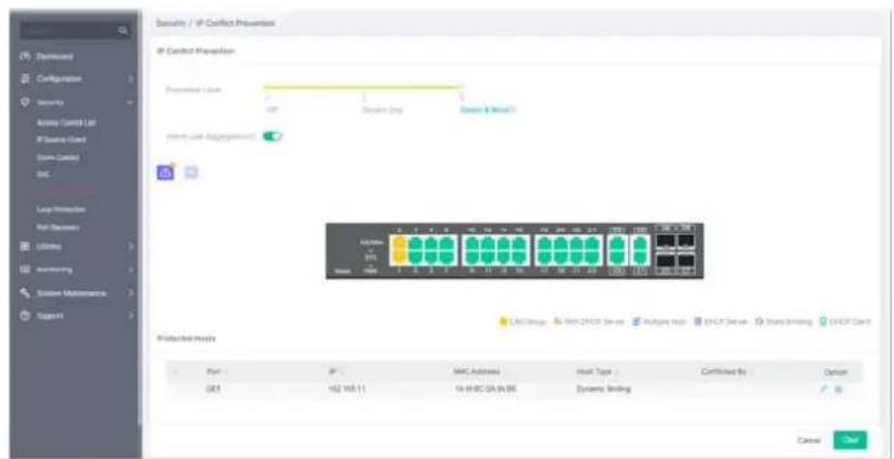
Permit Link Aggregation
It appears after running the quick start wizard for IP conflict prevention. The devices connected to the LAG ports will not be blocked due to using the same IP.
| Protected Host | |
| Port Displays the LAN port number (GE1 to GE28, LAG1 to LAG8) of the DHCP server. | |
| IP Displays the IP address of the DHCP server. | |
| MAC Address Displays the MAC address of the DHCP server. | |
| Host Type Displays the result of host type (e.g., Dynamic Binding) of the DHCP server. | |
| Conflicted By Displays the object conflicting with the host. | |
| Option | - Click to modify the settings of the selected port. - Click it to remove the selected entry. |
| Clear Click it to remove all entries. | |
After finishing this web page configuration, please click OK to save the settings.
To modify settings for a host, click the link of each port to open the setting page.
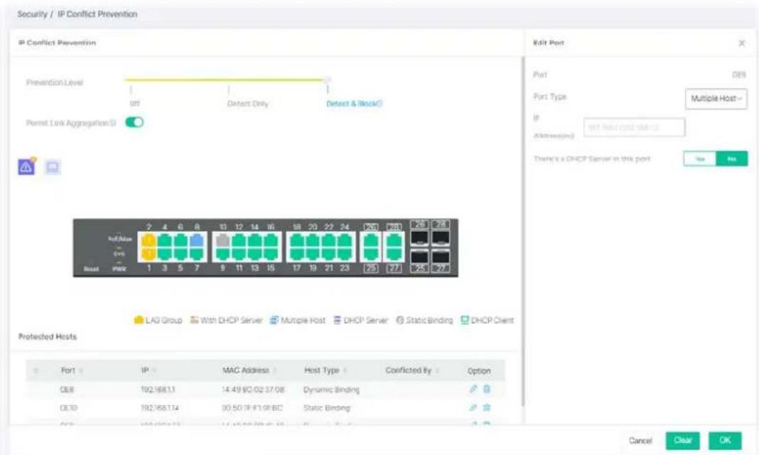
Available settings are explained as follows:
| Item | Description |
| Edit Port | |
| Port Displays the LAN port number (GE1 to GE28, LAG1 to LAG8) of the selected host. | |
| Port Type | Specify the port type for the selected host.DHCP ClientStatic BindingMultiple HostDHCP Server |
| IP Address(es) Enter the | IP address based on the port type. |
| There's a DHCP Server in this port | Yes - If there is a DHCP server in this port already, click Yes.No - If there is no DHCP server in this port already, click No. |
III-6 Loop Protection
Loop event might be caused due to wrong hardware connection. VigorSwitch will periodically send packets out to check if they loopback or not. This page allows you to set conditions and perform an action when VigorSwitch detects the looped packet.
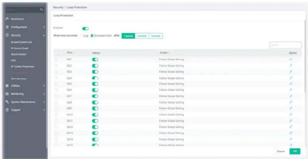
Available settings are explained as follows:
| Item | Description |
| Loop Protection | |
| Enable | Enable / Disable - Click the toggle to enable / disable this function. VigorSwitch will detect the loop event of the GE port automatically. - means "Enable". - means "Enable". - means "Disable". - means "Disable". |
| When loop occurred.. |  the switch detects loop situation occurred to a port; it will perform the action selected in this field. the switch detects loop situation occurred to a port; it will perform the action selected in this field. the switch will record such event as a log.[XHB4] down Port - The switch will shut down the port. the switch will record such event as a log.[XHB4] down Port - The switch will shut down the port. second/2 seconds/3 seconds - Determine the time to record second/2 seconds/3 seconds - Determine the time to record  ent and / or shutdown the port. ent and / or shutdown the port. Settings configured here will be treated as global setting for all GE Settings configured here will be treated as global setting for all GE  |
| Port Displays the port num |  (E1 to GE28). Check the box to the left to (E1 to GE28). Check the box to the left to  the selected port. the selected port. |
| Status |  / Disable - Click the toggle to enable / disable this function. / Disable - Click the toggle to enable / disable this function. |
| Action Display the specifie |  on for the selected port. on for the selected port. |
| Option |  - click to modify the loop protection settings of the selected port. - click to modify the loop protection settings of the selected port. |


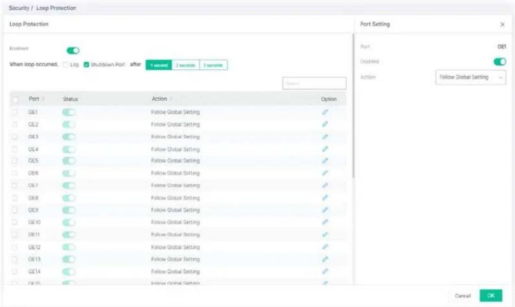
Available settings are explained as follows:
| Item | Description |
| Port Displays the port number (GE1 to GE28). | |
| Enable | Enable / Disable - Click the toggle to enable / disable this function. VigorSwitch will detect the loop event of the GE port automatically. - means "Enable". - means "Enable". - means "Disable". - means "Disable". |
| Action | Follow Global Setting - Adopts the settings configured for When loop occurred.Log - The switch will record such event as a log.Shutdown Port - The switch will shut down the port.Shutdown Port and Log - The switch will shut down the port and record the event as a log. The system administrator will view the content from system log. |
After finishing this web page configuration, please click OK to save the settings.
This page is used for configuring settings to recover the port which is being blocked by the following functions after a defined period of time.
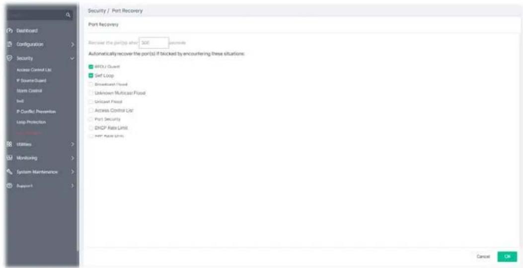
Available settings are explained as follows:
| Item | Description |
| Port Recovery | |
| Recover the port(s) after | The port being blocked will be able to receive and send traffic after the time period configured here. |
| Check the box to block the port(s) if encountering the situations listed below. | |
| BPDU Guard Checked - Recover the port being blocked by BPDU Guard after the time set in Recovery Interval. | |
| Self Loop Checked - Recover the port being blocked by self loop Guard after the time set in Recovery Interval. | |
| Broadcast Flood Checked - Recover the port being blocked by broadcast flood after the time set in Recovery Interval. | |
| Unknown Multicast Flood | Checked - Recover the port being blocked by unknown multicast flood after the time set in Recovery Interval. |
| Unicast Flood Checked - Recover the port being blocked by unicast flood after the time set in Recovery Interval. | |
| Access Control List | Checked - Recover the port being blocked by ACL after the time set in Recovery Interval. |
| Port Security Checked - Recover the port being blocked by port security after the time set in Recovery Interval. | |
| DHCP Rate Limit Checked - Recover the port being blocked by DHCP rate limit after the time set in Recovery Interval. | |
| ARP Rate Limit Checked - Recover the port being blocked by ARP rate limit after the time set in Recovery Interval. | |
This page is left blank.
Chapter IV Utilities

natural_image
Abstract geometric composition with four gray squares and one red diamond (no text or symbols)When the system administrator is unable to get Ping information from the targeted LAN port, Vigor system will send an alert e-mail to the system administrator.
The configuration result for each port will be displayed on the table listed on the lower side of this web page.
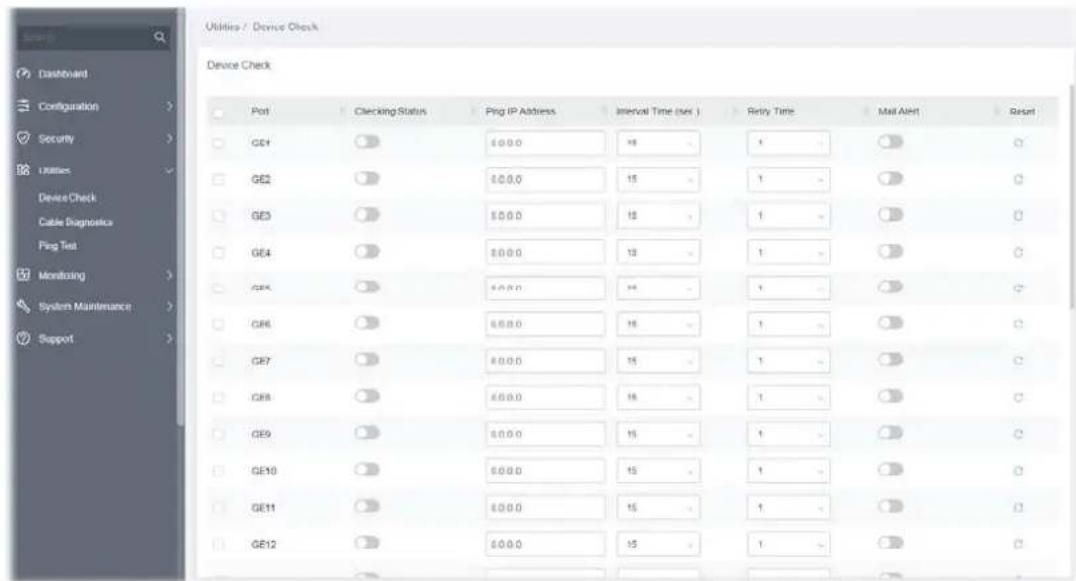
Available settings are explained as follows:
| Item | Description |
| Port Display the port number (GE1 to GE28).Check the box to the left to enable the port settings. | |
| Checking Status | Enable / Disable - Click the toggle to enable / disable this function. - means "Enable".- means "Disable". - means "Enable".- means "Disable". |
| Ping IP Address Enter the IP address of the PoE device for check. | |
| Interval Time(sec.) | The ping check will be performed every 15, 30, 60 or 120 seconds for the selected port (PoE device). |
| Retry Time The system will perform the ping check the selected port (PoE device) for 1, 3 or 5 times. | |
| Mail Alert | Enable / Disable - Click the toggle to enable / disable this function. |
| Reset | Clear current settings and return to factory default settings. |
After finishing this web page configuration, please click OK to save the settings.
IV-2 Cable Diagnostics
After finished copper test, the results will be shown on the lower side of this web page.
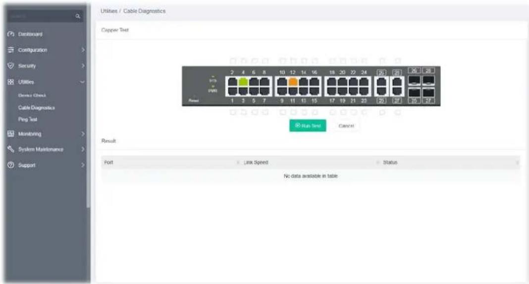
Available settings are explained as follows:
| Item | Description |
| Cooper Test | |
| Run Test Perform the copper test action. | Before clicking Run Test, select the port or ports (GE1 to GE28) on the panel figure for performing cable diagnostics. |
| Result | |
| Port Displays the port number that has been performed with cable diagnostics. | |
| Link Speed Displays the link speed of the port(s). | |
| Status Displays the connection status of the port(s). | |
After finishing this web page configuration, please click OK to save the settings.
IV-3 Ping Test
This page is used for configuring the ping test and perform the ping test.
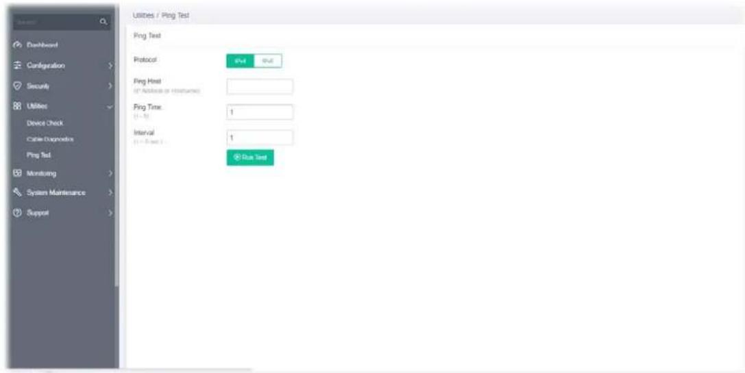
Available settings are explained as follows:
| Item | Description |
| Ping Test | |
| Protocol Choose IPv4/IPv6 to specify IP address for sending ping to check if network path is ok. | |
| Ping Host Enter the IP address of SNMP server based on the protocol selected above. | |
| Ping Time | It means how many times to send ping request packet.Enter a number between 1 and 5 as the count and the default configuration is 4. |
| Interval Defines the interval to perform ping action. For example, “1” means the ping action will be performed per second. | |
| Run Test Perform ping action. | |
Chapter V Monitoring

natural_image
Simple icon of a red heartbeat line inside a gray rectangular frame (no text or symbols)V-1-1 System Log Information
This page allows the user to set filtering conditions and displays the filtering result.
![Monitoring / Log Center System Log Information System Log Settings System Log Information Filter Case All Refresh Time Log Type Log Level Log Category Content Apr 13 07:52:42 RAM notice VLAN VLAN 10 name is changed to VLAN 10 Apr 13 07:52:41 RAM notice VLAN VLAN 10 is added, default name is VLAN0210 Apr 13 06:26:28 RAM notice AAA Successful login through Web [Username admin].JP 192.68.110 Apr 13:26:34 RAM notice POST Logistics@user.io ink up Apr 13:00:58 RAM notice System System restarted - Cold Start Apr 13:00:59 RAM notice System Logging is enabled Showing To Be Extries Show to entries](/content/2026/05/940937/images/5bf4f81037d3f0541e515e78847a4641e924e08aa24e4a1028c2abe0126f9aef.jpg)
Available settings are explained as follows:
| Item | Description |
| Filter Click to set the conditions for filtering. | 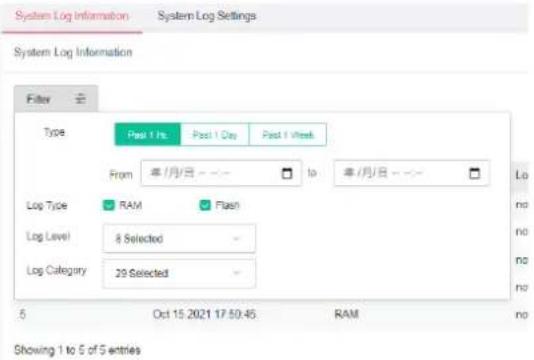 |
| Type - Specify the time (Past 1 Hour, Past 1 Day, Past 1 Week) for filtering.Log Type - Select RAM (explore the logs contained in volatile memory (also known as RAM) or Flash (explore the logs contained in non-volatile memory).Log Level - Select severity (emerg, alert, crit, error, warning, notice, info and debug) of log messages which you wish to filter out for review.Log Category - Select the categories (related features) of logs you wish to review. |
| Clear All Clear it to remove all logs displayed in this page. |
| Refresh Click it to refresh the log. |
| Time Displays the filtering time type. |
| Log Type Displays the log type (RAM or Flash). |
| Log Level Displays the severity of the log. |
| Log Category Displays the category of the log. |
| Content Displays the brief explanation of the log. |
V-1-2 System Log Settings
This page allows users to enable system logging into local Syslog and specific remote Syslog server for storage.
V-1-2-1 Local
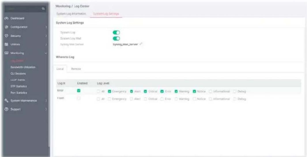
Available settings are explained as follows:
| Item | Description |
| System Log Settings | |
| System Log | Enable / Disable - Click the toggle to enable / disable this function.  - means “Enable”. - means “Disable”. - means “Enable”. - means “Disable”. |
| System Log Mail | Enable / Disable - Click the toggle to enable / disable this function. Syslog Mail Server - It is available when the System Log Mail is enabled. Click to configure Syslog Mail Server. |
| Where to Log | |
| Local | Log in - Displays the log type. |
Enable - Select the box to enable the log type (RAM/Flash).
Log Level - Select the box(es) to select the severity of the log.
To modify settings for the Syslog Mail Server, click the

link to open the setting page.
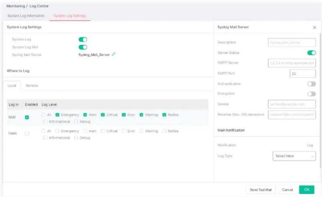
Available settings are explained as follows:
| Item | Description |
| Syslog Mail Server | |
| Description Displays the name of the Syslog Mail Server. | |
| Server Status | Enable / Disable - Click the toggle to enable / disable the Syslog Mail Server settings. - means "Enable".- means "Disable". - means "Enable".- means "Disable". |
| SMTP Server Enter IP address or URL of the SMTP server. | |
| SMTP Port Enter the port number for the SMTP server. | |
| Authentication | Enable / Disable - Click the toggle to enable / disable the authentication mechanism.Usage - Enter a user name for authentication.Password - Enter a password for authentication. |
| Encryption | Enable / Disable - Click the toggle to enable / disable this function. After enabling Authentication, choose one of the encryption servers for data encryption.STARTTLS - The mail will be encrypted with StartTLS.SSL/TLS - The mail will be encrypted with StartTLS. |
| Sender Enter the email address which will send the syslog mail out. | |
| Receiver Enter the email | address which will receive the syslog mail. |
| Mail Notification | |
| Log Type Vigor system will send the e-mail related to the selected feature(e.g., AAA, ACL) to the recipient. | |
| Send Test Mail | After clicking this button, VigorSwitch system will send a test mail to the recipient. |
After finishing this web page configuration, please click OK to save the settings.
V-1-2-2 Remote
This page allows users to enable system logging into a specific remote Syslog server for storage.
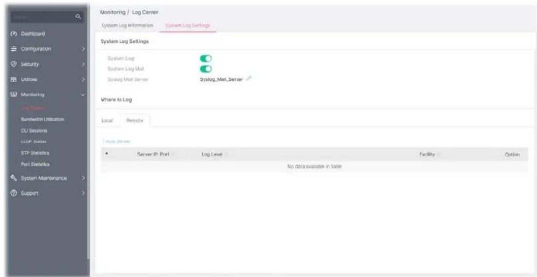
Available settings are explained as follows:
| Item | Description |
| System Log Settings | |
| System Log | Enable / Disable - Click the toggle to enable / disable this function.○ - means "Enable".○ - means "Disable". |
| System Log Mail | Enable / Disable - Click the toggle to enable / disable this function.Syslog Mail Server - It is available when the System Log Mail is enabled. Click to configure Syslog Mail Server. |
| Where to Log | |
| +Add Server Click to create a new remote server. | |
| Log In Displays the index number of the remote server. | |
| Server IP: Port Displays the IP address and port number used by the server. | |
| Log Level Displays the severity of the system log. | |
| Facility Displays the facility of the remote Syslog server. | |
To add a remote server, click the "+Add Server" to open the edit page.
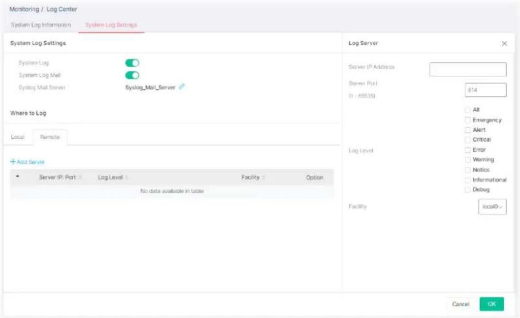
Available settings are explained as follows:
| Item | Description |
| Log Server | |
| Server IP Address Enter | IP address of the Syslog server. |
| Server Port Specify the port that syslog should be sent to. | |
| Log Level Select severity | (emerg, alert, crit, error, warning, notice, info and debug) of log messages which will be stored. |
| Facility One device supports multiple facilities (represented with facility ID, local0 to local7) of remote Syslog server. For each facility ID contains different Syslog server configuration, please choose a facility ID for this Syslog server. | |
After finishing this web page configuration, please click OK to save the settings.
V-2 Bandwidth Utilization
This page offers the traffic statistics including data information and data of interframe gap for each port (GE1 to GE28).
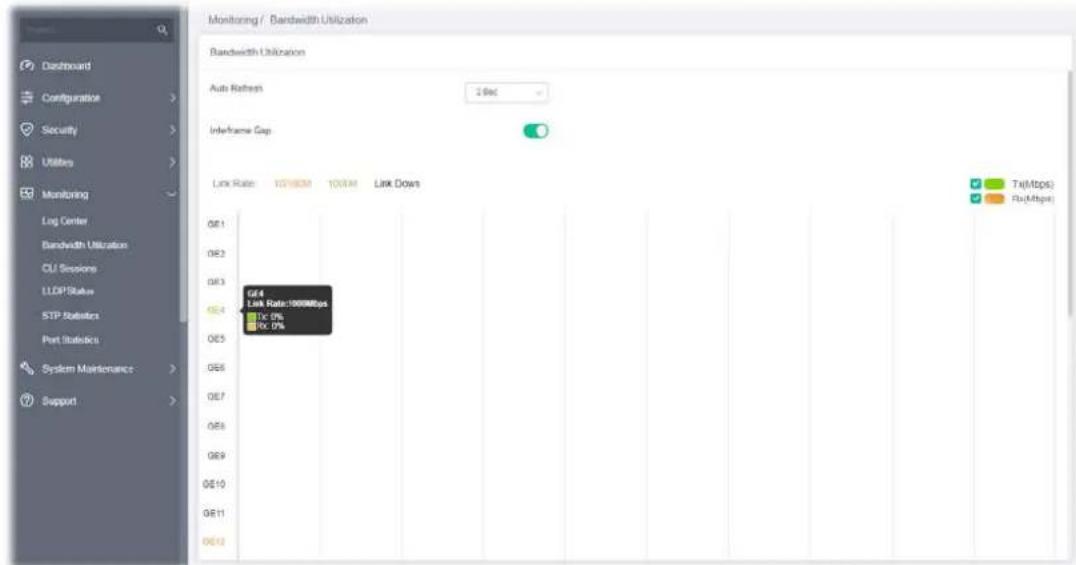
Available settings are explained as follows:
| Item | Description |
| Auto Refresh Select the time interval for refreshing this page. | |
| Interframe Gap | The data of the interframe gap can be displayed or hidden by enabling/disabling for Interframe Gap.Enable / Disable - Click the toggle to enable / disable this function. - means "Enable".- means "Disable". - means "Enable".- means "Disable". |
V-3 CLI Sessions
This page shows a list of CLI command executed. You can delete the selected CLI session by click the Remove button under the Edit item.
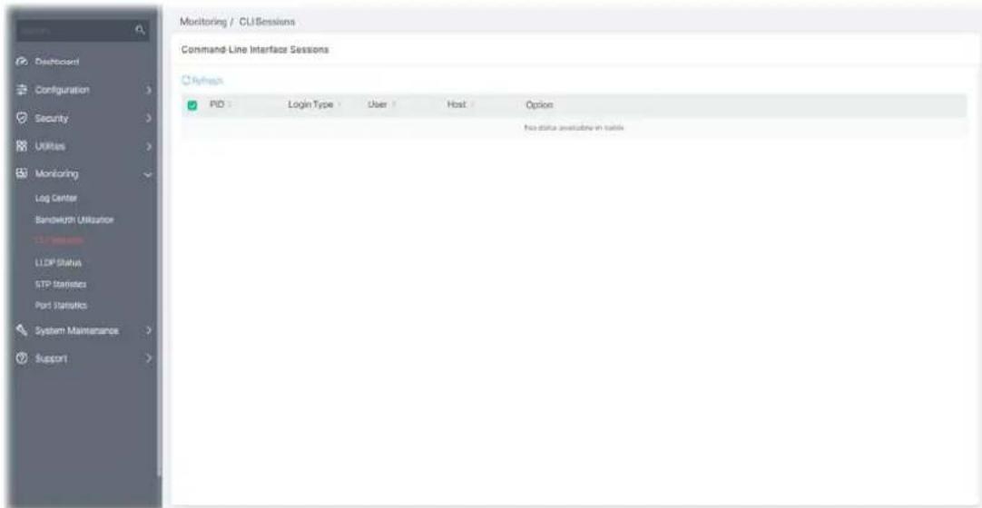
V-4-1 General Statistics
This page offers the statistics of LLDP packets of each port (GE1 to GE28).
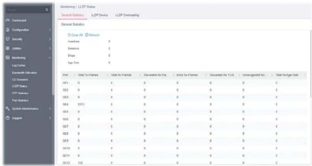
Available settings are explained as follows:
| Item | Description |
| General Statistics | |
| Clear All Clear it to remove all logs displayed in this page. | |
| Refresh Click it to refresh the status page. | |
V-4-2 LLDP Device
This page displays information for LLDP local and remote devices.
V-4-2-1 Local
This page displays information for LLDP local device.
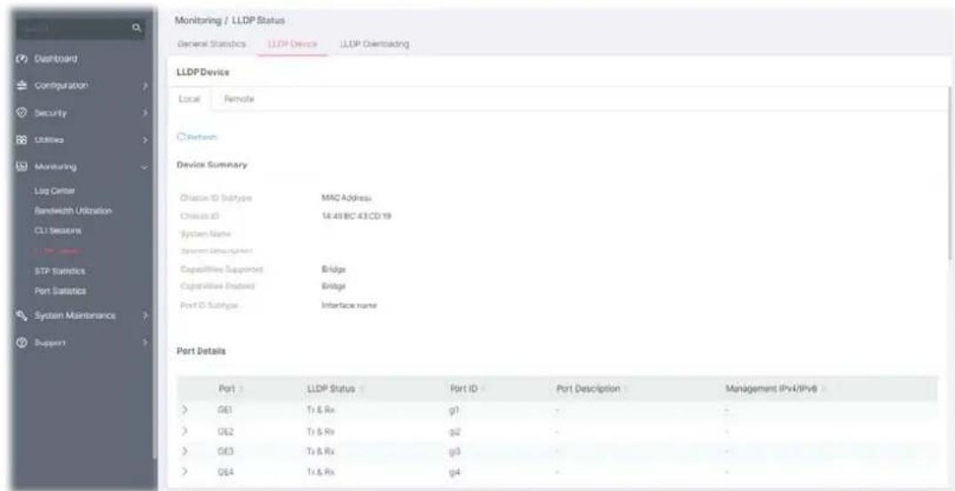
Available settings are explained as follows:
| Item | Description |
| Refresh Click it to refresh the status page. | |
| Device Summary | Display a summary of the LLDP Information for this switch.Chassis ID Subtype - Display the type of chassis ID, such as the MAC address.Chassis ID - Display Identifier of chassis. Where the chassis ID subtype is a MAC address, the MAC address of the switch is displayed.System Name - Display model name of switch.System Description - Display description of switch.Capabilities Supported - Display the primary functions of the device, such as Bridge, WLAN AP, or Router.Capabilities Enabled - Primary enabled functions of the device.Port ID Subtype - Display the type of the port identifier that is shown. |
| Port Details Display detailed information of the selected GE port.Click > to review the detailed information contained in TLVs sent out from each interface, containing MAC/PHY, 802.3, 802.3 Link Aggregation, 802.1 VLAN and Protocol for each LAN port (GE1 to GE28). | |
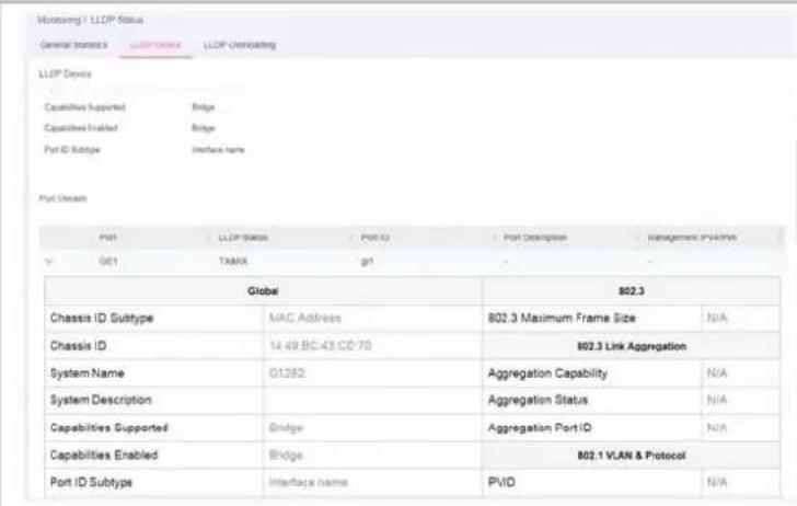
V-4-2-2 Remote
This page is used to view the information sent from neighboring devices by LLDP protocol.
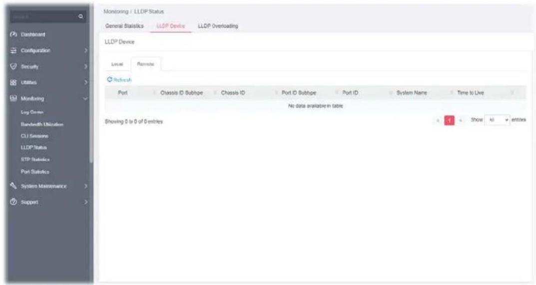
Available settings are explained as follows:
| Item | Description |
| Refresh Click it to refresh the status page. | |
| Port Displays the number of the local port to which the neighbor is connected. | |
| Chassis ID Subtype Displays the type of chassis ID (for example, MAC address). | |
| Chassis ID Displays the identifier of the 802 LAN neighboring device's chassis. | |
| Port ID Subtype Displays the type of port identifier. | |
| Port ID Displays the number of port identifier. | |
| System Name Displays the name of the switch. | |
| Time to Live Displays the time interval in seconds after which the information for remote device will be deleted. | |
V-4-3 LLDP Overloading
This page allows user to review current size, overall size of LLDP packet and whether it is to exceed maximum allowed size of single LLDP packet.
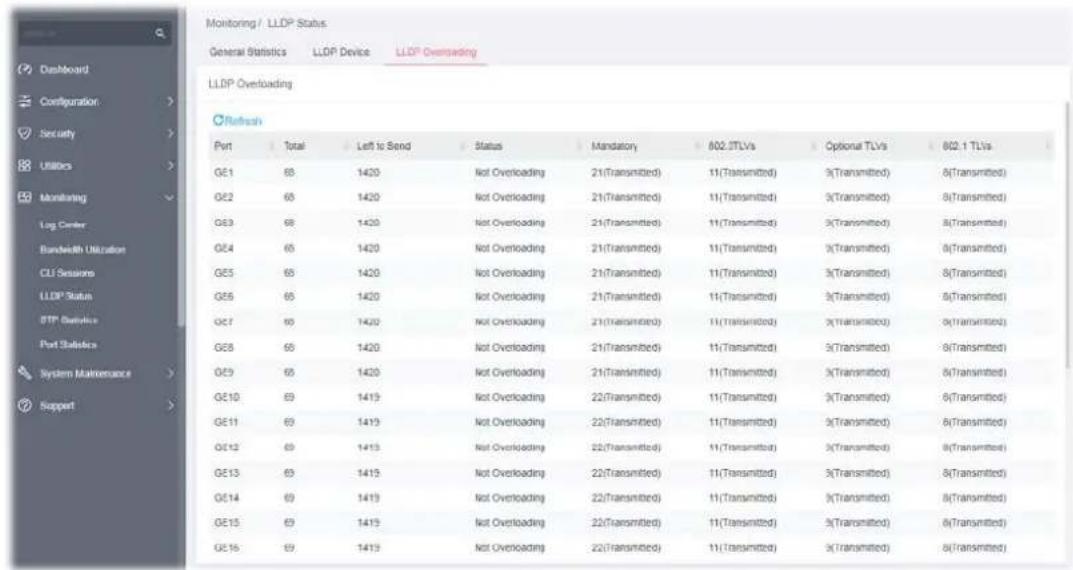
Available settings are explained as follows:
| Item | Description |
| Refresh Click it to refresh the status page. | |
| Port | Displays the name of the port. |
| Total | Displays the total number of bytes of LLDP information in each packet. |
| Left to Send | Displays the total number of available bytes left for additional LLDP information in each packet. |
| Status | Displays if LLDP TLVs has overloaded the PDU maximum size or not. |
| Mandatory | Displays how many bytes used by mandatory TLVs. |
| 802.3TLVs | Displays how many bytes used by 802.3 TLVs. |
| Optional TLVs | Displays how many bytes used by optional TLVs. |
| 802.1 TLVs | Displays how many bytes used by 802.1 TLVs. |
The Spanning Tree Protocol (STP) can be used to detect and disable network loops, and to provide backup links between switches, bridges, or routers.
This page allows users to edit the general setting of the STP CIST port and browser CIST port status.
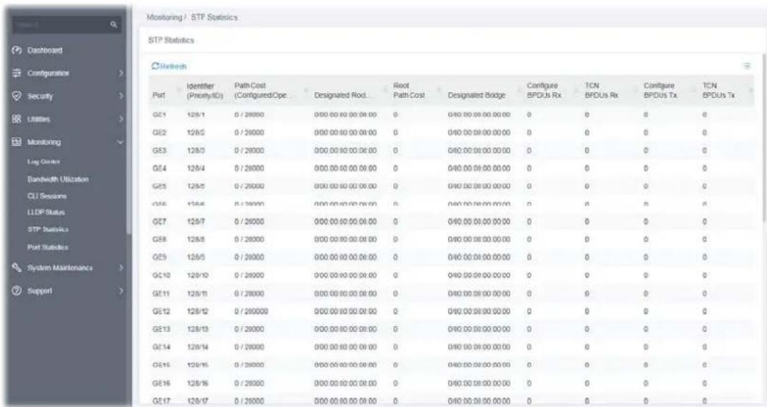
Available settings are explained as follows:
| Item | Description |
| Refresh Click it to refresh the status page. | |
| Port Displays the interface number for GE and LAG. | |
| Identifier Displays the spanning tree port identifier. | |
| Path Cost Displays current path cost of given port. | |
| Designated Root Bridge | Displays the identifier of designated root bridge. |
| Root Path Cost | Displays the operational root path cost. |
| Designated Bridge | Displays the identifier of next bridge on this port. |
| Configure BPDUs Rx | Displays the counts of the received CONFIG BPDU. |
| TCN BPDUs Rx. | Displays the counts of the received TCN BPDU. |
| Configure BPDUs Tx. | Displays the counts of the transmitted CONFIG BPDU. |
| TCN BPDUs Tx | Displays the counts of the transmitted TCN BPDU. |
This feature displays statistics (including port error statistics) for GE/LAG ports.
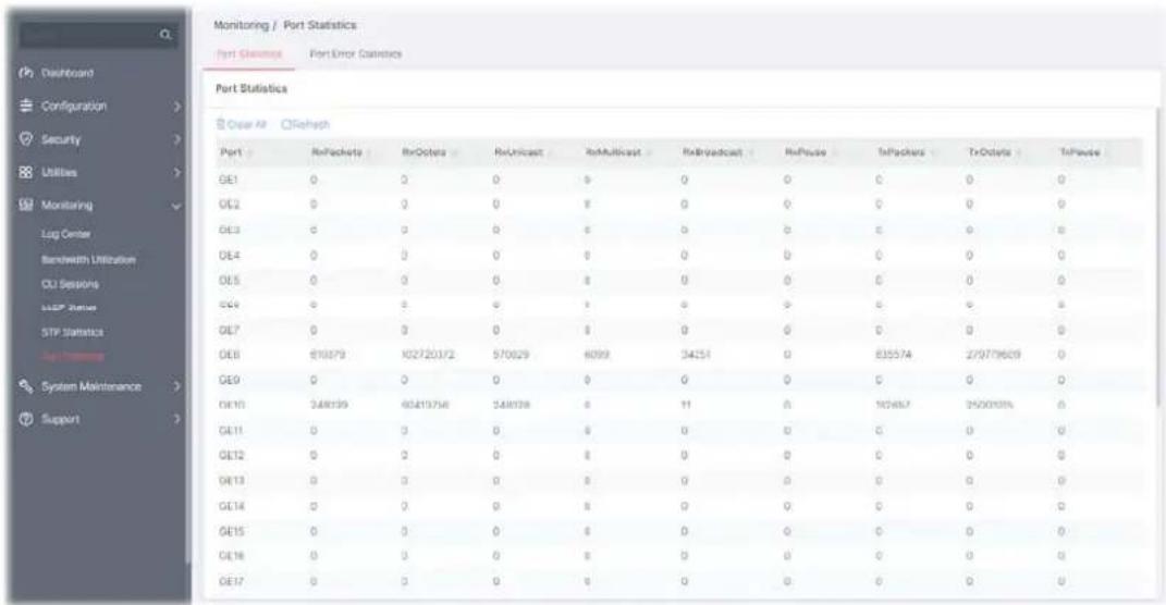
Available settings are explained as follows:
| Item | Description |
| Clear All Clear it to remove all logs displayed in this page. | |
| Refresh Click it to refresh the status page. | |
| Port Displays the port number (GE1 to GE28). | |
Chapter VI System Maintenance

natural_image
Abstract graphic with a gray gear and red line, no text or symbols present.VI-1-1 Device Info
This page displays general information (name, location and contact) for the VigorSwitch.
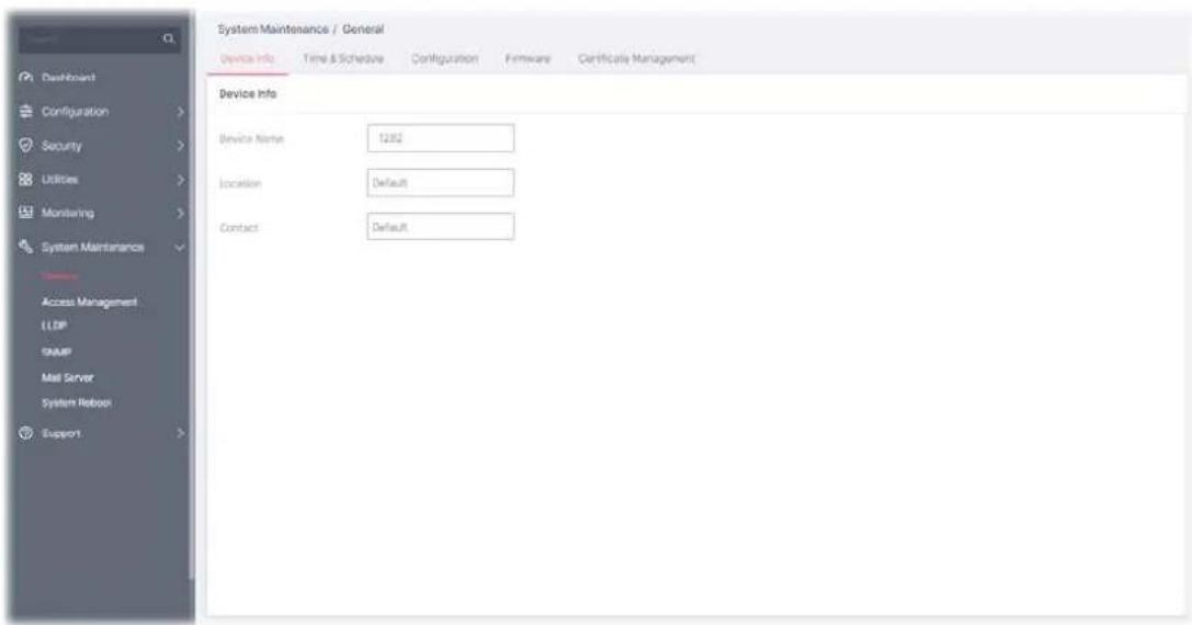
Available settings are explained as follows:
| Item | Description |
| Device Name Displays the name of this VigorSwitch. Change the name if required. | |
| Location Define the location of this VigorSwitch. | |
| Contact Define the contact information of this VigorSwitch. | |
After finishing this web page configuration, please click OK to save the settings.
VI-1-2 Time & Schedule
This page allows users to configure maximum 15 schedule rules.
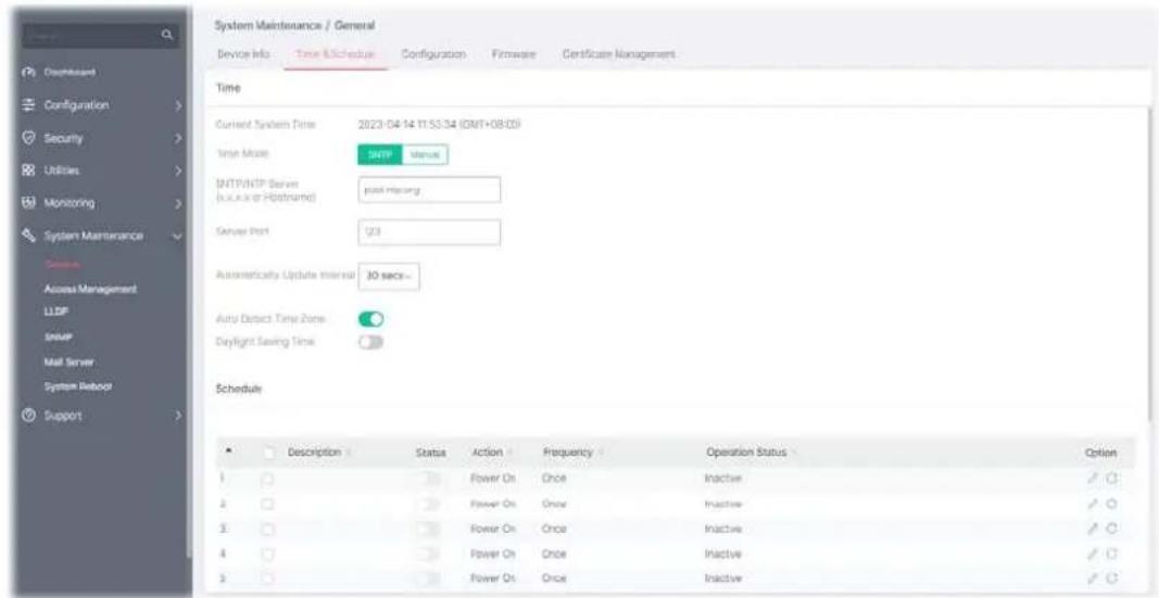
Available settings are explained as follows:
| Item | Description |
| Time | |
| Current System Time Display current system time based on the time server. | |
| Time Mode | Select SNTP or Manual.If SNTP is selected, configure:SNTP/NTP Server - Enter the web site of the time server or the IP address of the server.Server Port - Enter the port number use by the time server.Automatically Update Interval - Set the interval (30 secs, 1 min, 3 mins, 5 mins, 10 mins and etc.) for the system to update the time automatically.If Manual is selected, configure:Manual Time - Specify static time (year, month, day, hours, minutes and seconds) manually.Auto Detect Time Zone - Click the toggle to enable / disable this function.- means “Enable”.- means “Disable”.Time Zone - Select a time zone for the switch if the Auto Detect Time Zone option is disabled.Daylight Saving Time - Click the toggle to enable / disable this function. If enabled, select the mode of daylight saving time.Recurring - Using recurring mode of daylight saving time.Non-Recurring - Using non-recurring mode of daylight savingtime.USA -Using daylight saving time in the United States that starts on the second Sunday of March and ends on the first Sunday of November.European - Using daylight saving time in the Europe that starts on the last Sunday. |
| whenRecurringis selected | Daylight Saving Time Offset - Specify the adjust offset of daylight saving time.Recurring From - Specify the starting time of recurring daylight saving time.Recurring To - Specify the ending time of recurring daylight saving time. |
| whenNon-Recurringis selected | Daylight Saving Time Offset - Specify the adjust offset of daylight saving time.Non-recurring From - Specify the starting time of non-recurring daylight saving time.Non-recurring To - Specify the ending time of recurring daylight saving time. |
| Option | Click to modify the setting page of the selected schedule profile.Clear current settings and return to factory default settings. |
After finishing this web page configuration, please click OK to save the settings.
To edit a schedule profile, click to open the edit page for the selected schedule profile.
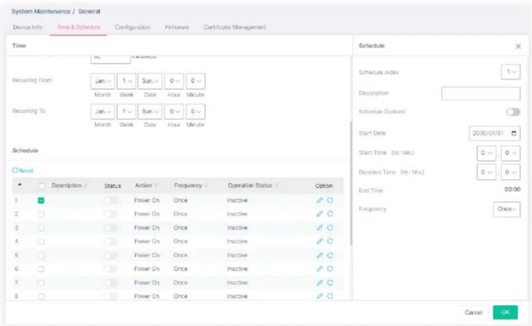
Available settings are explained as follows:
| Item | Description |
| Schedule | |
| Schedule Index Use the drop down list to choose one schedule profile. | |
| Description Enter a brief comment for such schedule. | |
| Schedule Enable Click the toggle to enable / disable this function. | - means "Enable". The selected schedule profile will take action as configured. - means "Disable". The selected schedule profile will not take action but be saved for future use. |
| Start Date Specify the starting date of the schedule by choosing from a drop down calendar. | |
| Start Time Specify the starting time of the schedule by using the drop down list to specify the starting hours and minutes. | |
| Duration Time Specify the ending time of the schedule by using the drop down list to specify the ending hours and minutes. | |
| End Time Displays the time period setting. | |
| Frequency Specify how often the schedule will be applied. | Once - The schedule will be applied just once.Weekdays Routine - Specify which days in one week should perform the schedule.Every - Check to select the days in a week.Monthly Routine - Specify the day in a month as the starting point.Duration Time - Use the drop down list to select the date in a month.Few Days Routine - The period of cycle duration is between 1 day and 31 days. For example, 7 means the whole cycle is 7 days; 20 means the whole cycle is 20 days. When the time is up, the PoE device will be turned on of off automatically.Every - Use the drop down list to select the date in a month. |
After finishing this web page configuration, please click OK to save the settings. A new schedule profile will be shown on the page.
VI-1-3 Configuration
Configuration Backup allows a user to backup the firmware image or configuration file on the switch to remote TFTP server or host file system through HTTP protocol.
Configuration Restore allows a user to upgrade the firmware image or configuration file on the switch to remote TFTP server or host file system through HTTP protocol.
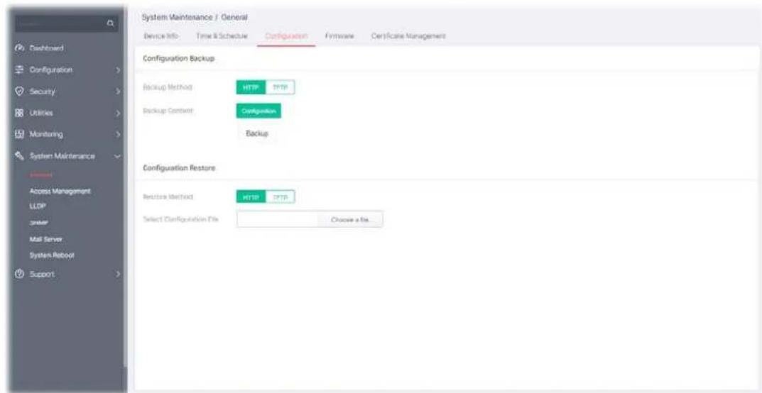
Available settings are explained as follows:
| Item | Description |
| Configuration Backup | |
| Backup Method Select Backup method. | HTTP - Use WEB browser to backup firmware.TFTP - Use TFTP to backup firmware.Server IP Address - Enter the IPv4/IPv6 address for the TFTP server. |
| Backup Content | Backup - Make a backup copy for the configurations for VigorSwitch. |
| Configuration Restore | |
| Restore Method | Select Restore method.HTTP - Use WEB browser to restore firmware.Select Configuration File - Choose the file which will be used to restore the configuration settings.TFTP - Use TFTP to restore firmware.Server IP Address - Enter the IPv4/IPv6 address for the TFTP server.File Name - Enter the firmware image or configuration file name on the TFTP server. |
After finishing this web page configuration, please click OK to save the settings.
VI-1-4 Firmware
This page allows a user to upgrade the firmware image or configuration file on the switch to remote TFTP server or host file system through HTTP protocol.
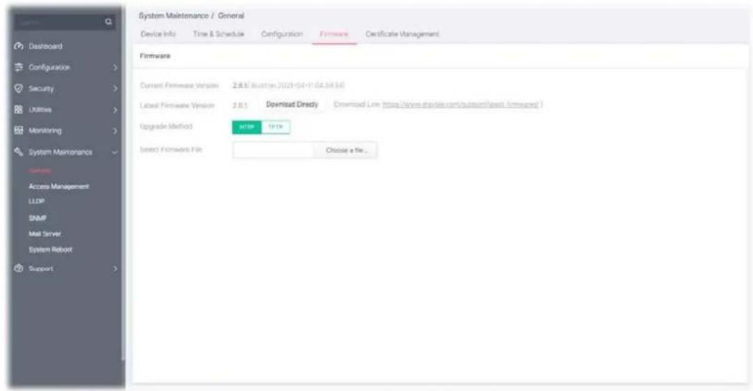
Available settings are explained as follows:
| Item | Description |
| Firmware | |
| Current Firmware Version | Display current used firmware. |
| Last Firmware Version | Display the latest firmware version. |
| Upgrade Method | Select Upgrade method:HTTP - Use WEB browser to upgrade firmware.Select Firmware File - Choose the firmware file located in your computer.TFTP - Use TFTP to upgrade firmware.Server IP Address - Enter the IPv4/IPv6 address for the TFTP server.File Name - Enter the firmware image or configuration file name on the TFTP server. |
After finishing this web page configuration, please click OK to save the settings.
VI-1-5 Certificate Management
The digital certificate is an electronic document issued by a certification authority (CA) to an entity to prove ownership of a public key. It contains identifying information including the issued-to party's name, serial number, expiration dates, etc., and the digital signature of the certificate-issuing authority so that a recipient can verify that the certificate is actual.
VigorSwitch is capable of generating a new certificate as a CA server does. This page allows you to fill required information for developing a new certificate.
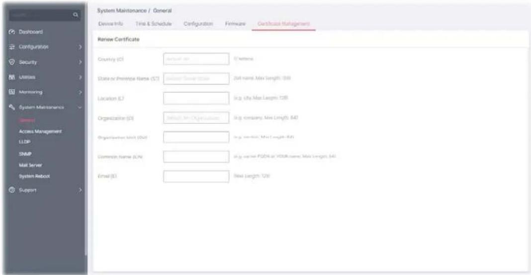
Available settings are explained as follows:
| Item | Description |
| Country(C) | Enter the country code (e.g., TW) in which your organization is located. |
| State or Province Name(ST) | Enter the state or province where your organization is located. |
| Location (L) Enter the city where you're your organization is located. | |
| Organization (O) Enter the legal name of your organization. | |
| Organization Unit (OU) | Enter the department within your organization that you wish to be associated with this certificate. |
| Common Name (CN) Enter the fully-qualified domain name / WAN IP that will be used to reach your server. | |
| Email (E) Enter the email address of the entry. | |
| OK Click to generate a new certificate. | |
VI-2 Access Management
VI-2-1 LAN Access
The switch needs an IP address for it to be managed over the network. The factory default IP address is 192.168.1.224. The subnet mask specifies the network number portion of an IP address. The factory default subnet mask is 255.255.255.0.
Use the IP Address (IPv4/IPv6) screen to configure the switch IP address and the default gateway device. The gateway field specifies the IP address of the gateway (next hop) for outgoing traffic. In addition, this page allows the network administrator to change the VLAN ID of management access. Management access protocols such as http, https, SNMP and etc., are only accessible from the VLAN specified as management VLAN.
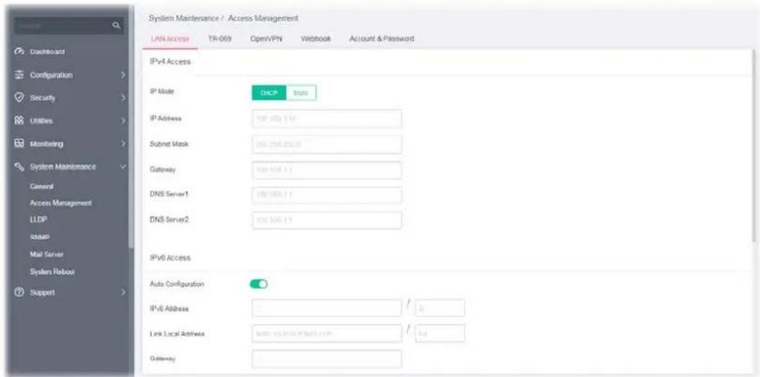
Available settings are explained as follows:
| Item | Description |
| IPv4 Access | |
| IP Mode Select the mode of network connection. | |
| DHCP - Use static IPv4 address. | |
| Static - Use DHCP provisioned IP address and Gateway if feasible. | |
| IP Address - Enter the IP address of your switch in dotted decimal notation for example 192.168.1.224. If static mode is enabled, enter IP address in this field. | |
| Subnet Mask - Enter the IP subnet mask of your switch in dotted decimal notation for example 255.255.255.0. If static mode is enabled, enter subnet mask in this field. | |
| Gateway - Enter the IP address of the gateway in dotted decimal notation. If static mode is enabled, enter gateway address in this field. | |
| DNS Server1/2 - Enter primary/ secondary DNS server address in this field. | |
IPv6 Access
Auto Configuration Enabled - Let the switch automatically configure IPv6 address.
Click the toggle to enable / disable this function.

- means "Enable".

- means "Disable".
DHCPv6 Client - Enable this feature if there is a DHCPv6 server on your network for assigning IPv6 Address, instead of using Router Advertisement.
Disabled -
IPv6 Address - Enter the IPv6 address of your switch. If auto configuration mode is disabled, enter IPv6 address in this field.
Gateway - Enter the IPv6 address of the router as your default IPv6 gateway to access IPv6 Internet or other IPv6 network.
DNS Server1/2 - Enter primary/ secondary DNS server address in this field.
Management VLAN
Management VLAN Select the VLAN ID as management VLAN.
Protocol Access
HTTP Server, HTTPS Server, Telnet Server, SSH Server, Enforce HTTPS Server
Select the protocol(s) for remote access.
After finishing this web page configuration, please click OK to save the settings.
VI-2-2 TR-069
This page allows a user to configure TR-069 settings for connecting to VigorACS 3.
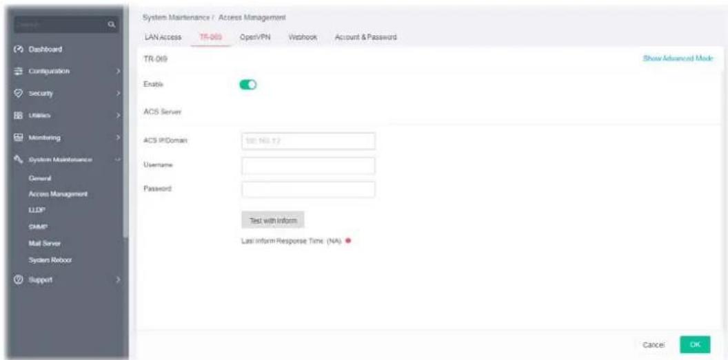
Available settings are explained as follows:
Item
Description
| Show/Hide Advanced Mode | Click to display / hide the advanced mode settings. |
TR-069 Click the toggle to enable / disable this function. | - means "Enable".- means "Disable". |
| Basic Mode - ACS Server | |
| ACS IP/Domain | Enter the IP address or domain name of the server. |
| Username Enter the username that you want to link with the VigorACS (Auto Configuration Server). | |
| Password Enter the password that you want to link with the VigorACS (Auto Configuration Server). | |
| Test with Inform | Click to send a message to test if this CPE is able to communicate with VigorACS server. |
| Advanced Mode - ACS Server | |
| Protocol | Choose HTTP or HTTPS for connecting with VigorACS. |
| Port Enter a value that VigorACS can use to access to this switch. | |
| ACS IP/Domain | Enter the IP address or domain name of the server. |
| Handler Enter the URL that you want to link with the VigorACS (Auto Configuration Server). | |
| Username Enter the username that you want to link with the VigorACS (Auto Configuration Server). | |
| Password Enter the password that you want to link with the VigorACS (Auto Configuration Server). | |
| Test with Inform | Click to send a message to test if this CPE is able to communicate with VigorACS server. |
| CPE Settings | |
| CPE Client | Choose HTTP or HTTPS for connecting with VigorACS. |
| URL Display the URL of VigorSwitch | |
| Port Enter a value that VigorACS can use to access to this switch. | |
| Username | Enter the username that VigorACS can use to access into this switch. |
| Password | Enter the password that VigorACS can use to access into this switch. |
| TLS Version | |
| TLS Minimum Protocol Version | Due to security consideration, the built-in HTTPS VPN server of the router had upgraded to TLS1.x protocol (TLS1.2/TLS1.3). Select one of the versions. |
| Periodic Inform | |
| Enable Click the toggle to enable/disable the function. | |
| Interval Time Set the interval time for the switch to send notification to CPE. | |
| STUN Settings | |
| Enable Click the toggle to enable / disable this function. | - means "Enable".- means "Disable". |
| Server Address Enter the IP address of the STUN server. | |
| Server port Enter the port number of the STUN server. | |
| Minimum Keep Alive Period | If the STUN server is enabled, the switch must send binding request to the server for the purpose of maintaining the binding in the Gateway. Please type a number as the minimum period. The default setting is "60 seconds". |
| Maximum Keep Alive Period | If the STUN server is enabled, the switch must send binding request to the server for the purpose of maintaining the binding in the Gateway. Please type a number as the maximum period. A value of "-1" indicates that no maximum period is specified. |
| Notification | |
| Port Link Up/Down | Vigor system will check the health status of LAN ports including link up /down, or speed change.Select LAN port(s) to do the health check of port link. |
| Link Speed Change Select LAN port(s) to do the health check of speed change. | |
After finishing this web page configuration, please click OK to save the settings.
VI-2-3 OpenVPN
Devices connecting to VigorSwitch can transmit data to remote end via OpenVPN to ensure the information security.
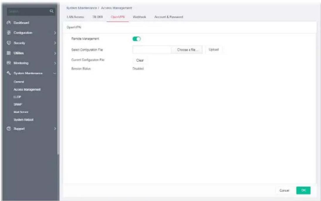
Available settings are explained as follows:
| Item | Description |
| Remote Management | Click the toggle to enable / disable OpenVPN tunnel between VigorSwitch with the remote end.  - means “Enable”. - means “Disable”. - means “Enable”. - means “Disable”. |
| Select Configuration File | It is available when remote management is enabled. As a VPN client, please import the OpenVPN config file coming from OpenVPN server. |
| Current Configuration File | Click to remove current configuration file. |
| Session Status | Display current OpenVPN status (Disabled, Connecting or Success). |
After finishing this web page configuration, please click OK to save the settings.
VI-2-4 Webhook
Without getting any request, VigorSwitch will send the data (if available) that a user concerned to the specified URL (provided by remote client) automatically.
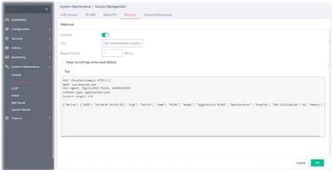
Available settings are explained as follows:
| Item | Description |
| Enable | Click the toggle to enable / disable the webhook service. The data will be transmitted to the specified URL. - means “Enable”.- means “Disable”. - means “Enable”.- means “Disable”. |
| URL | Specify the destination to receive the real-time data by entering the URL.Please get the URL from the client who wants to obtain the newest and available data automatically from the Vigor switch. |
| Repeat Period Set the transmission interval (unit is minute). | |
| Keep my settings while reset default | Check the box to keep the webhook configuration when resetting VigorSwitch with default settings. |
| Test Vigor system will send a test report to the remote address. | |
After finishing this web page configuration, please click OK to save the settings.
VI-2-5 Account & Password
This page allows a user to add or delete local user on switch database for authentication.
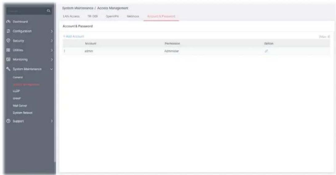
Available settings are explained as follows:
| Item | Description |
| +Add Account Click to create a new account. | |
| Account Displays the name of the account. | |
| Permission Displays the privilege level (Admin or View Only) of the account. | |
| Option | - Click to modify the account settings. |
To modify an existing account profile, click the link of of the one to be changed.
To add a schedule profile, click the "+ Add Account " to open the edit page.
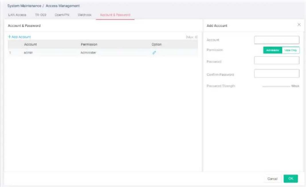
Available settings are explained as follows:
| Item | Description |
| Add Account | |
| Account Enter a username for new account. | If you want to modify an existed user account, simply enter the same string in this field. Then, modify the password and choose privilege level. After clickingApply, the existed user name will be modified with different values. |
| Permission | Administer - Allow to change switch settings.View Only- See switch settings only. Not allow to change it. |
| Password Enter a password for new account. | |
| Confirm Password Enter the password again for confirmation. | |
| Password Strength | Displays the strength of the password, indicated by the words “weak”, “medium” or “strong”. |
After finishing this web page configuration, please click OK to save the settings.
LLDP is a one-way protocol; there are no request/response sequences. Information is advertised by stations implementing the transmit function, and is received and processed by stations implementing the receive function. The LLDP category contains LLDP and LLDP-MED pages.
VI-3-1 LLDP Port Setting
This page allows a user to select specified port or all ports to configure LLDP state.
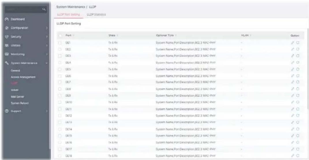
Available settings are explained as follows:
| Item | Description |
| Port Displays the index number of GE ports (GE1 to GE28). | |
| Status | Displays the transmission of LLDP PDUs. |
| Optional TLVs | Displays the data communication protocols and optional information. |
| VLAN | Displays the VLAN ID number. |
| Option | - Click to modify the LLDP port settings of the selected port.- Clear current settings and return to factory default settings. |
To modify the port settings for the selected port, click the link of of the one to be changed.
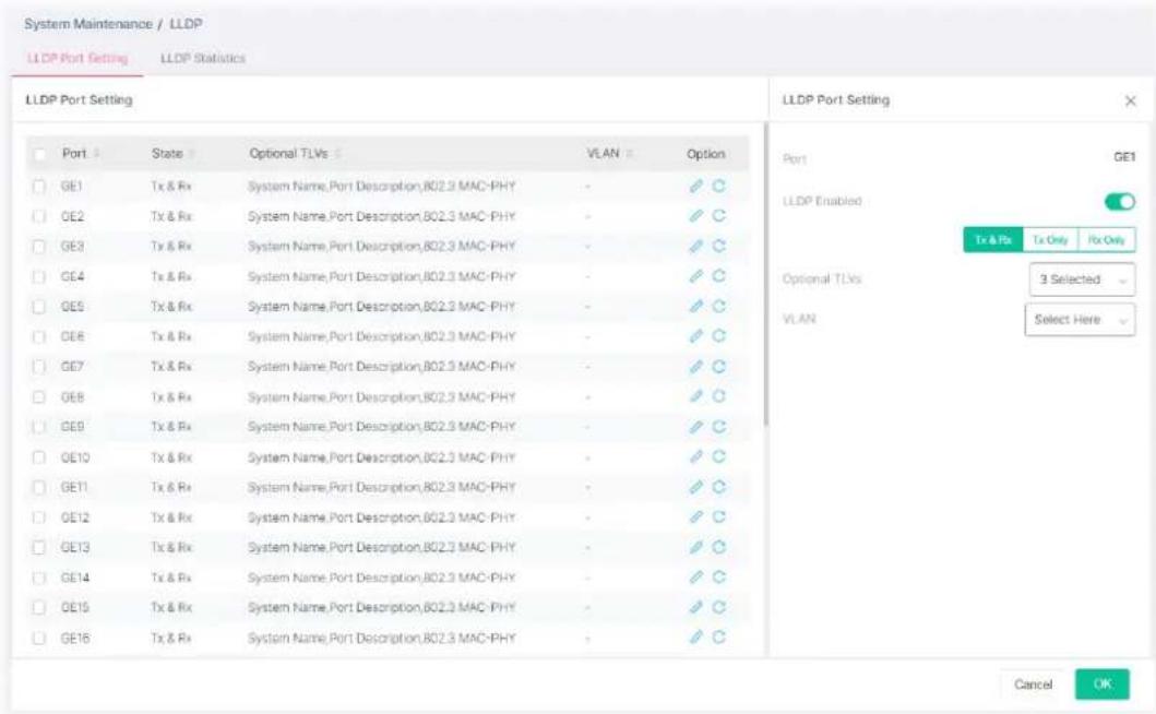
Available settings are explained as follows:
| Item | Option |
| Port Displays the index n |  |
| [7DD2] | |
 f GE port. f GE port. | |
 | |
| LLDP Enable | [GC74]e toggle to enable / disable this function. |
| [AA14] | |
 | |
 | |
 | |
 - means "Enable". - means "Enable". | |
| [CCST] | |
 - Transmit and receive LLDP PDUs both. - Transmit and receive LLDP PDUs both. | |
| [4WCA] | |
 √ - Transmit LLDP PDUs only. √ - Transmit LLDP PDUs only. | |
 √ - Receive LLDP PDUs only. √ - Receive LLDP PDUs only. | |
| [CT87] | |
| Optional TLVs | [TA97] |
 | |
| [RW80] | |
 | |
| [KXLT] | |
 e and length are fixed in size (typically 1-4 bytes), and the held is of variable size. e and length are fixed in size (typically 1-4 bytes), and the held is of variable size. | |
| [C7AX] | |
| [CTV] | |
 | |
| [PDCC] | |
 | |
| [CYC] | |
 tion, System Capability, 802.3 MAC-PHY, 802.3 Link tion, System Capability, 802.3 MAC-PHY, 802.3 Link | |
| [37KVA]tion, 802.3 Maximum Frame Size, Management Address and VID. | |
| VLAN Select the VLAN ID |  |
| [WY74]to be performed (multiple selections are | |
 . . | |
 | |
| OK Save the settings. | [7DK7] |
 |



































VI-3-2 LLDP Statistics
This page offers the statistics of LLDP packets (in, out and error) of each port (GE1 to GE28).
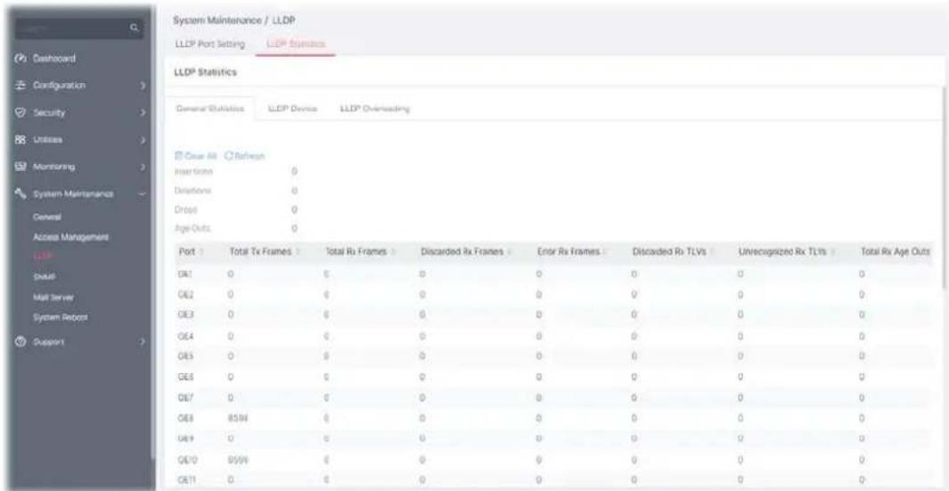
Available settings are explained as follows:
| Item | Description |
| Clear All | Clear it to remove all logs displayed in this page. |
| Refresh Click it to refresh the log. | |
Simple Network Management Protocol (SNMP) is an "Internet-standard protocol for managing devices on IP networks". Devices that typically support SNMP include routers, switches, servers, workstations, printers, modem racks and more.
SNMP is used mostly in network management systems to monitor network-attached devices for conditions that warrant administrative attention.
SNMP is a component of the Internet Protocol Suite as defined by the Internet Engineering Task Force (IETF). It consists of a set of standards for network management, including an application layer protocol, a database schema, and a set of data objects.
An SNMP-managed network consists of three key components:
- Managed device
- Agent - software which runs on managed devices
• Network management station (NMS) - software which runs on the manager
A managed device is a network node that implements an SNMP interface that allows unidirectional (read-only) or bidirectional (read and write) access to node-specific information. Managed devices exchange node-specific information with the NMSs. Sometimes called network elements, the managed devices can be any type of device, including, but not limited to, routers, access servers, switches, bridges, hubs, IP telephones, IP video cameras, computer hosts, and printers.
An agent is a network-management software module that resides on a managed device. An agent has local knowledge of management information and translates that information to or from an SNMP-specific form.
A network management station (NMS) executes applications that monitor and control managed devices. NMSs provide the bulk of the processing and memory resources required for network management. One or more NMSs may exist on any managed network.
VI-4-1 View
This page allows the network administrator to create MIB views (Management information base) and then include or exclude OID (Object Identifier) in a view.
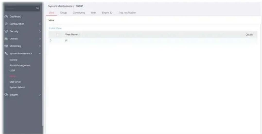
Available settings are explained as follows:
| Item | Description |
| +Add View Click it to add a new MIB view profile. | |
| View Name Displays the name of the MIB view. | |
To add a schedule profile, click the "+ Add View" to open the edit page.
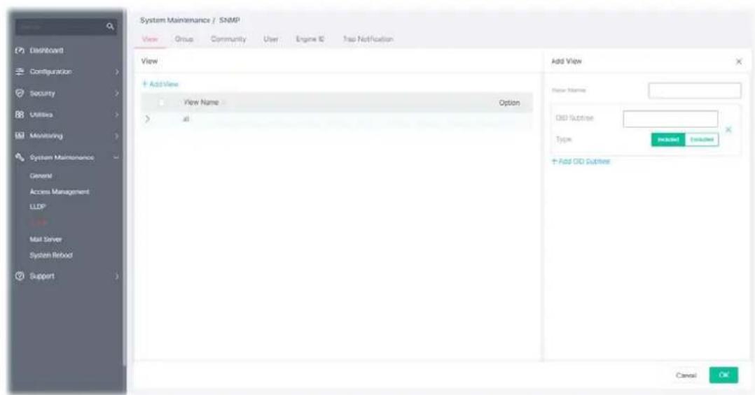
Available settings are explained as follows:
| Item | Description |
| View Name Enter a name of the MIB view. | |
| OID Subtree Enter an OID string to be included or excluded (based on the view | |
| type setting) from the MIB view. | |
| Type Determine to include or exclude the selected MIBs. | |
| +Add OID Subtree Click it to add a new MIB view profile. | |
After finishing this web page configuration, please click OK to save the settings.
VI-4-2 Group
This page allows the network administrator to group SNMP users and assign different authorization and access privileges.
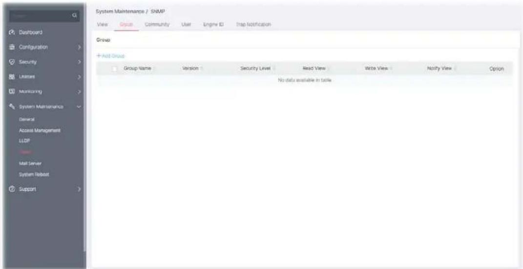
Available settings are explained as follows:
| Item | Description |
| +Add Group Click it to create a new group profile. | |
| Group Name Displays the name for the group. | |
| Version Displays the SNMP version adopted by the group. | |
| Security Level | Displays the SNMP security level for the group. |
| Read View Displays the read view profile. | |
| Write View Displays the write view profile. | |
| Notify View Displays the notify view profile. | |
To add a schedule profile, click the "+ Add Group " to open the edit page.
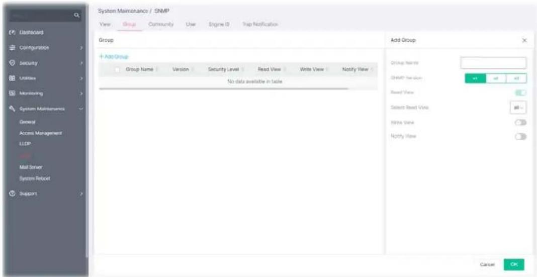
Available settings are explained as follows:
| Item | Description |
| Add Group | |
| Group Name Enter a name for the group. | |
| SNMP Version Specify SNMP version (v1, v2 or v3). | |
| Security Level Specify SNMP security level for the group. It is available when SNMPv3 is selected.No Security - No authentication.Authentication - Authentication without encryption will be performed for packets.Authentication and Privacy - Authentication with encryption will be performed for packets. | |
| Read View Click the toggle to enable / disable this function. If it is enabled, users of this group have the right to read the selected MIB view.- means “Enable”.- means “Disable”. | |
| Select Read View | Use the drop down list to select one of the views. The default is “all”, which means the group user can read all MIB views. |
| Write View | Click the toggle to enable / disable this function. If it is enabled, users of this group have the right to write the selected MIB view.Select Write View - Use the drop down list to select one of the views. The default is “all”, which means the group user can write all MIB views. |
| Notify View | Click the toggle to enable / disable this function. If it is enabled, users of this group have the right to send notifications for the selected MIB view.Select Notify View - Use the drop down list to select one of the views. The default is “all”, which means the group user have the right to send notification for all MIB views. |
After finishing this web page configuration, please click OK to save the settings.
VI-4-3 Community
This page allows a user to add/remove multiple communities of SNMP.
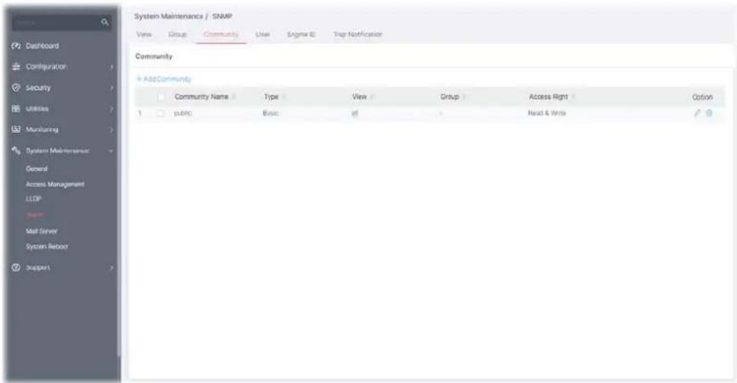
Available settings are explained as follows:
| Item | Description |
| +Add Community Click it to add a new community. | |
| Community Name Displays the community name. | |
| Type Displays | |
| View Displays | |
| Group Displays the name of the group. | |
| Access Right | Displays the accessing right (read, read and write) that this community has. |
| Option | - Click to modify the settings of the community. - Remove the selected entry. |
To modify an existing community profile, click the link of of the one to be changed.
To add a schedule profile, click the "+ Add Community " to open the edit page.
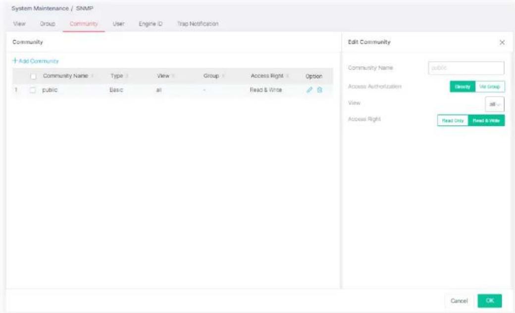
Available settings are explained as follows:
| Item | Description |
| Add Community | |
| Community Name Enter a name as community name. The maximum length of the text is limited to 23 characters. | |
| Access Authorization Directly - View and access right can be specified for this SNMP community profile.Via Group - Specify one of the SNMP groups for this SNMP community profile. | |
| View | Simply specify one of the view profiles from the drop down list. |
| Group | It is available whenVia Groupis selected as access authorization.Specify a SNMP group to define the object available to the community. |
| Access Right Define the access right of the community group. | |
| Read Only- It allows unidirectional access to node-specific information.Read & Write- It allows bidirectional access to node-specific information. | |
After finishing this web page configuration, please click OK to save the settings.
VI-4-4 User
This page allows a user to configure SNMP user profile(s).
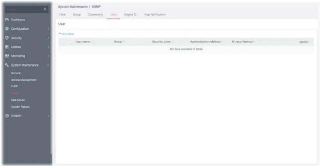
Available settings are explained as follows:
| Item | Description |
| +Add User Click it to add a new user profile. | |
| User Name Displays the name of this user profile. | |
| Group | Displays the group name to which this user profile belongs. |
| Security Level | Displays the security method used by this user profile. |
| Authentication Method | Displays the authentication method used by this user profile. |
| Privacy Method | Displays the privacy method used by this user profile. |
To modify an existing user profile, click the link of of the one to be changed.
To add a user profile, click the "+ Add User" to open the edit page.
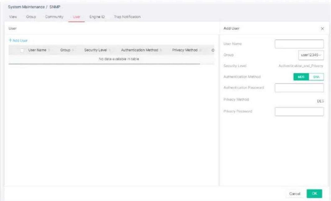
Available settings are explained as follows:
| Item | Description |
| Add User | |
| User Name Enter a name for creating new SNMP user. | |
| Group | Select one of theSNMPgroups from the drop down list. Then, this user profile will be grouped under the selected SNMP group. |
| Security Level Displays the security level configured for the selected SNMP group.If the selected group is not aSNMPv3group, nothing will be displayed in this field. | |
| For SNMPv3 group only | |
| Authentication Method | It is available only when the Security Level is set with "Authentication", or "Authentication_and_Privacy".You can change the methods (None, MD5, SHA) for the selected SNMPv3 group. If no method is available for you to select, that means the selected SNMPv3 group is set with No Security. |
| Authentication Password | It is available only when the Security Level is set with "Authentication", or "Authentication_and_Privacy".Enter a string as the password for authentication. |
| Privacy Method It is available only when the Security Level is set with "Authentication_and_Privacy".You can change the methods (None, DES) for the selected SNMPv3 group. If no method is available for you to select, that means the selected SNMPv3 group is set with No privacy. | |
| Privacy Password It is available only when the Security Level is set with "Authentication_and_Privacy".Enter a string as the password for authentication. | |
After finishing this web page configuration, please click OK to save the settings.
VI-4-5 Engine ID
This page allows a user to configure and display SNMP local and remote engine ID.
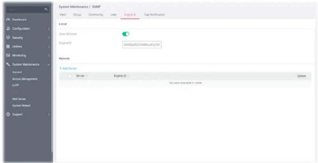
Available settings are explained as follows:
| Item | Description |
| Local | |
| User Defined | Click the toggle to enable / disable this function.  - means "Enable".- means "Disable". - means "Enable".- means "Disable". |
| Engine ID Displays the engine ID of the local server.The default Engine ID which is made up of MAC and Enterprise ID will be used instead. | |
| Remote | |
| +Add Server | Click it to create a new remote server profile. |
| Server Displays the hostname/IP address of the server. | |
| Engine ID Displays the engine ID of the remote server. | |
| Option | - Click to modify the server setting.- Clear the selected entry. |
To modify an existing server profile, click the link of of the one to be changed.
To add a remote server profile, click the "+ Add Server " to open the page.
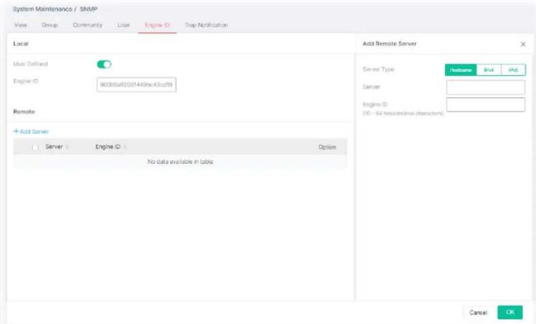
Available settings are explained as follows:
| Item | Description |
| Add Remote Server | |
| Server Type | Specify the address type for entering hostname or IPv4/IPv6 address.HostnameIPv4IPv6 |
| Server | Enter the IP address or the hostname of the remote SNMP server. |
| Engine ID Specify the engine ID for remote SNMP server.The engine ID ranges from 10 to 64 hexadecimal characters, and the hexadecimal number must be divided by "2". | |
After finishing this web page configuration, please click OK to save the settings.
VI-4-6 Trap Notification
This page allows a user to add or delete the SNMP trap receiver IP address and community name. In addition, it allows a user to configure a host to receive SNMPv1/v2/ve notification.
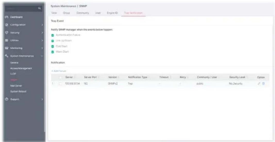
Available settings are explained as follows:
| Item | Description |
| Trap Event | |
| AuthenticationFailure, Link Up/Down,Cold Start, Warm Start | Check the box to enable the function.Authentication Failure- VigorSwitch will reboot when encountering authentication failure (including community not match or user password not match).Link Up/Down- VigorSwitch will reboot while encountering port link up or down trap.Cold Start- VigorSwitch will reboot while encountering user trap.Warm Start- VigorSwitch will reboot while encountering power down trap. |
| Notification | |
| +Add Server | Click it to create a new notification server profile. |
| Server Displays IPv4/IPv6/Hostname of the SNMP trap recipients. | |
| Server Port | Displays the UDP port number for the recipient's server. |
| Version Displays the notification SNMP version. | |
| Notification Type | Displays the notification type (Trap or Inform). |
| Timeout Displays the number of SNMP informs timeout. | |
| Retry Displays the number of SNMP informs retry count. | |
| Community/User Displays the community profile. | |
| Security Level | Displays the security level for SNMP notification packet. |
| Option | Click to modify the setting page of the server profile.Remove the selected entry. |
To modify an existing server profile, click the link of of the one to be changed.
To add a user profile, click the "+ Add Server " to open the edit page.
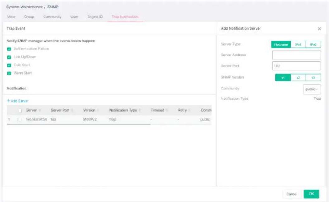
Available settings are explained as follows:
| Item | Description |
| Add Notification Server | |
| Server Type | Choose IPv4/IPv6/Hostname to specify IP address or the hostname of the SNMP trap recipients.HostnameIPv4IPv6 |
| Server Address | Specify SNMP notification version (SNMPv1/v2/v3). |
| Server Port Specify a port number for the server. | |
| SNMP Version | Specify SNMP notification version (SNMPv1/v2/v3). |
| Community | Use the drop down list to choose one of the community profiles. |
| Notification Type Displays the notification type.To specify Notification Type, select v2 or v3 as SNMP Version.Trap -Send SNMP traps to the host.Inform - Send SNMP informs to the host. If it is used, Timeout and Retry also shall be defined. | |
| Timeout | Specify the SNMP informs timeout. It is available whenInformis selected asType. |
| Retry | Specify the SNMP informs retry count. It is available whenInformis selected as Type. |
| User It is available when v3 is selected as SNMP Version. | |
| Security Level It is available when v3 is selected as SNMP Version.Specify SNMP security level for SNMP notification packet. It is available | |
| when SNMPv3 is selected.No Security – No authentication.Authentication – Authentication without encryption will be performed for packets.Authentication and Privacy – Authentication with encryption will be performed for packets. | |
After finishing this web page configuration, please click OK to save the settings.
This page allows a user to configure settings for VigorSwitch to send alert mail or Syslog mail when encountering certain situation.
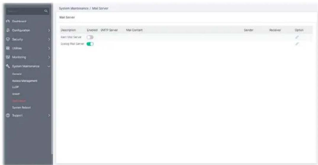
Available settings are explained as follows:
| Item | Description |
| Mail Server | |
| Description Displays the name of the mail server. | |
| Status | Click the toggle to enable / disable this function. - means "Enable".- means "Disable". - means "Enable".- means "Disable". |
| SMTP Server | Displays the IP address / host of the SMTP server. |
| Mail Content | Displays the condition(s) for VigorSwitch system to send a mail out. |
| Sender Displays the email address sending the alert/syslog mail. | |
| Receiver | Displays the email address receiving the alert/syslog mail. |
| Option | - Click to modify the setting page of the server profile. |
Alert Mail Server
To modify the alert mail server profile, click the link of

of Alert Mail Server to be changed.
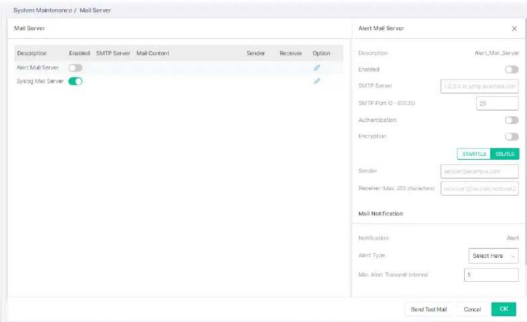
Available settings are explained as follows:
| Item | Description |
| Alert Mail Server | |
| Description Displays the name (Alert or Syslog) of the mail server. | |
| Server Status | Click the toggle to enable / disable the mail server. - means "Enable".- means "Disable". - means "Enable".- means "Disable". |
| SMTP Server Enter IP address or URL of the SMTP server. | |
| SMTP Port Enter the port number for the SMTP server. | |
| Authentication Click the toggle to enable / disable this function.User Name - Enter a user name for authentication.Password - Enter a password for authentication. | |
| Encryption Click the toggle to enable / disable this function.After enabling Authentication, choose one of the encryption servers for data encryption.STARTTLS - The mail will be encrypted with StartTLS.SSL/TLS - The mail will be encrypted with SSL/TLS. | |
| Sender Enter the email address which will send the alert mail out. | |
| Receiver Enter the email address which will receive the alert mail. | |
| Mail Notification | |
| Alert Type | Specify the condition(s) for VigorSwitch system to send an alert out.Port Link StatusPort Link SpeedSystem RestartedIP ConflictDevice CheckONVIF Throughput Threshold |
| Min. Alert Transmit Interval | Set a time interval for VigorSwitch system to send an alert out from the specified sender. |
| Send Test Mail | After clicking this button, VigorSwitch system will send a test mail to the recipient. |
After finishing this web page configuration, please click OK to save the settings.
Syslog Mail Server
To modify the Syslog mail server profile, click the link of of Syslog Mail Server to be changed.
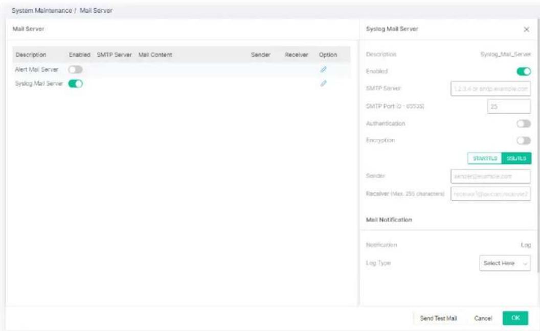
Available settings are explained as follows:
| Item | Description |
| Alert Mail Server | |
| Description | Displays the name (Alert or Syslog) of the mail server. |
| Server Status | Click the toggle to enable / disable this function. - means "Enable".- means "Disable". - means "Enable".- means "Disable". |
| SMTP Server Enter IP address or URL of the SMTP server. | |
| SMTP Port Enter the port number for the SMTP server. | |
| Authentication Click the toggle to enable / disable this function.User Name - Enter a user name for authentication.Password - Enter a password for authentication. | |
| Encryption Click the toggle to enable / disable this function. | |
| After enabling Authentication, choose one of the encryption servers for data encryption. | |
| STARTTLS - The mail will be encrypted with StartTLS. | |
| SSL/TLS - The mail will be encrypted with SSL/TLS. | |
| Sender Enter the email address which will send the syslog mail out. | |
| Receiver Enter the email address which will receive the syslog mail. | |
| Mail Notification | |
| Log Type Vigor system will send the e-mail related to the selected feature(e.g., AAA, ACL) to the recipient. | |
| Send Test Mail | After clicking this button, VigorSwitch system will send a test mail to the recipient. |
After finishing this web page configuration, please click OK to save the settings.
VI-6 System Reboot
This page allows you to reboot VigorSwitch with current settings or return to factory default settings for VigorSwitch.
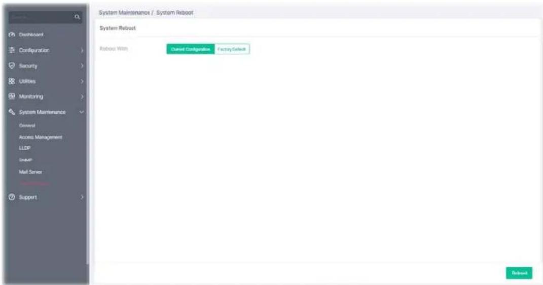
Available settings are explained as follows:
| Item | Description |
| System Reboot | |
| Reboot With | Current Configuration - Use current configuration settings. Factory Default - Use the default configuration settings. |
| Reboot Click to reboot the device immediately. | |
Chapter VII Troubleshooting

natural_image
Red and black crossed wrench and nut icons (no text or symbols)VII-1 Backing to Factory Default Setting
Sometimes, a wrong connection can be improved by returning to the default settings. Try to reset the modem by software or hardware.
Warning:
After pressing factory default setting, you will loose all settings you did before. Make sure you have recorded all useful settings before you pressing. The password of factory default is null.
VII-1-1 Software Reset
You can reset the modem to factory default via Web page.
Go to System Maintenance and choose System Reboot on the web page. The following screen will appear. Choose Factory Default and click OK. After few seconds, the modem will return all the settings to the factory settings.
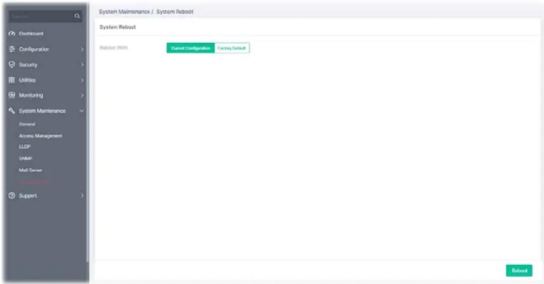
VII-1-2 Hardware Reset
While the modem is running, press the RST button and hold for more than 5 seconds. When you see the ACT LED blinks rapidly, please release the button. Then, the modem will restart with the default configuration.

After restore the factory default setting, you can configure the settings for the modem again to fit your personal request.
VII-2 Contacting DrayTek
If the modem still cannot work correctly after trying many efforts, please contact your dealer for further help right away. For any questions, please feel free to send e-mail to support@draytek.com.
Appendix Telnet Commands

natural_image
Abstract graphic of a red wrench crossed with two black hexagons, no text or symbols present.A-1 Accessing Telnet of Vigor Switch
This chapter also gives you a general description for accessing telnet and describes the firmware versions for the routers explained in this manual.
Note:
For Windows 7 user, please make sure the Windows Features of Telnet Client has been turned on under Control Panel>>Programs.
Type cmd and press Enter. The Telnet terminal will be open later.
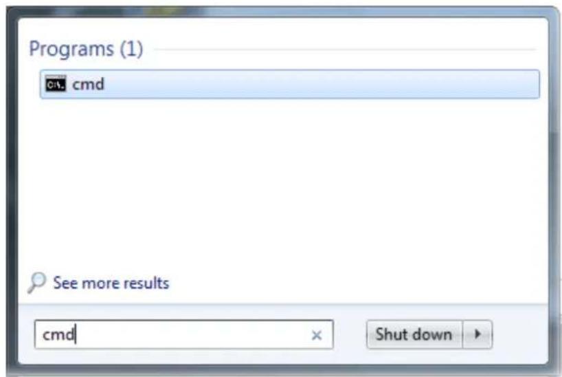
In the following window, type Telnet 192.168.1.224 as below and press Enter. Note that the IP address in the example is the default address of the router. If you have changed the default, enter the current IP address of the router and press Enter.
![Microsoft Windows [版本 6.1.7601] Copyright (c) 2009 Microsoft Corporation. All rights reserved. C:\Users\Carrie>telnet 192.168.1.224_](/content/2026/05/940937/images/9f4481e6a3ed5917f0de244e484a669948e1dc7e03cc036bde37c30c44deb600.jpg)
For users using previous Windows system (e.g., XP), simply click Start >> Run and type Telnet 192.168.1.224 in the Open box.
Next, enter admin/admin for Account/Password.
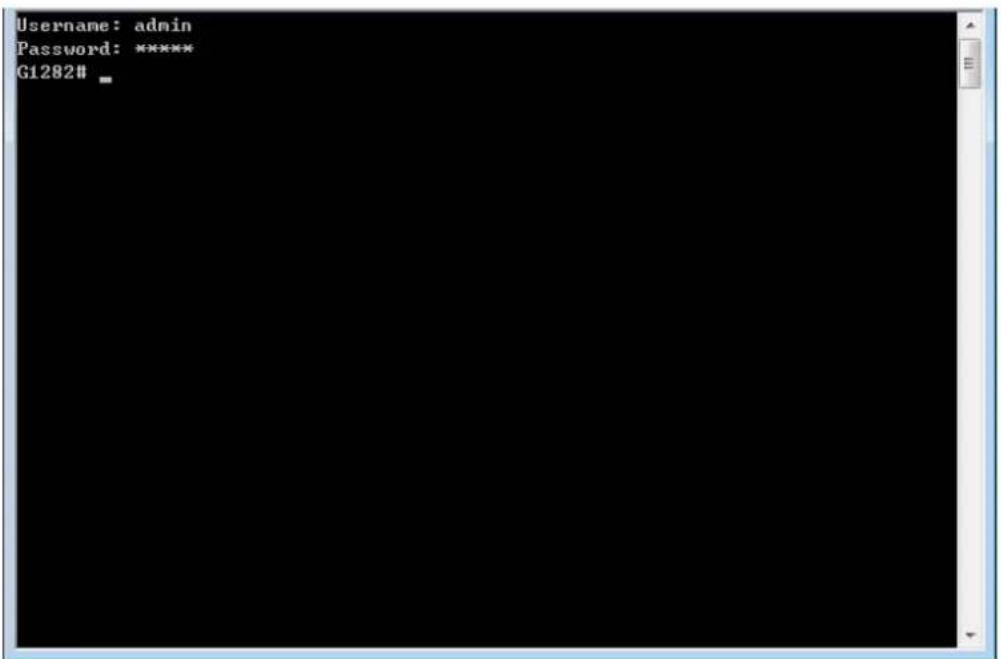
Enter? to get a list of available commands.
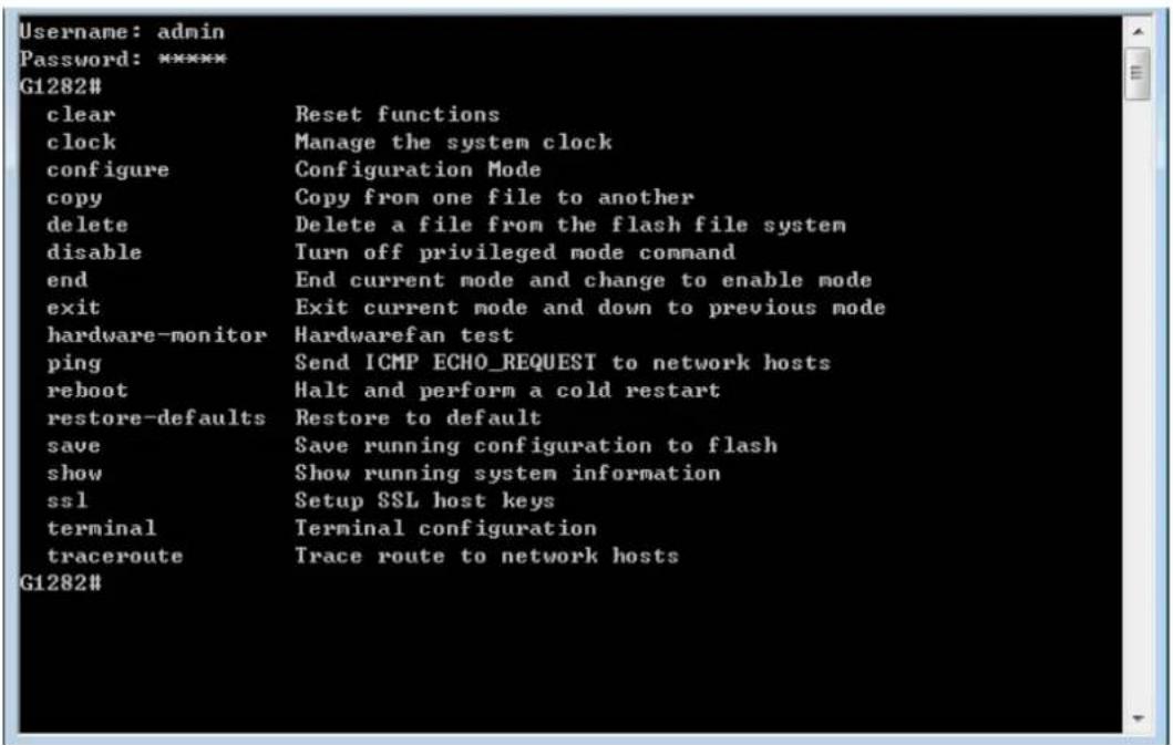
The available commands contain - clear, clock, configure, copy, delete, disable, end, exit, hardware-monitor, ping, reboot, restore-defaults, save, show, ssl, terminal, and traceroute. Each command will be explained as follows.
Note: You can also enter ? to check if there are subcommands under current command.
A-2-1 Clear Configuration
This command allows resetting the functions of ARP, interface, IP, IPv6, LACP, Line, LLDP, Logging, MAC, and Spanning Tree.
Telnet Command: clear arp
Use this command to clear entries in the ARP cache.
Syntax Items
clear arp
Description
| Syntax Items Description | |
| clear arp - Enter the | IP address of the device (e.g., 192.168.1.224).Related Syntax:# clear arp# clear arp |
Example
G1282# clear arp 192.168.1.224
G1282#
Telnet Command: clear interfaces
Use this command to clear statistics counters for all interfaces or a specific interface (10GB LAN, LAN or LAG).
Syntax Items
clear interfaces GigabitEthernet
clear interfaces LAG
Description
| Syntax Items Description | |
| clear interfaces GigabitEthernet | Specify a LAN interface for clearing statistics counters on that port.<1-28> - Enter the number (1 to 28) of LAN port.Related Syntax:# clear interfaces gigabitEthernet <1-28> counters |
| clear interfaces LAG Specify a | LAG interface for clearing statistics counters on that port.<1-8> - Enter the number (1 to 8) of LAG interface (IEEE 802.3 Link Aggregation Interface).Related Syntax:# clear interfaces LAG <1-8> counters |
Example
G1282# clear interfaces gigabitethernet 3 counters
G1282# clear interfaces
G1282# clear interfaces lag 2 counters
G1282#
Telnet Command: clear ip
Use this command to clear IGMP snooping groups (dynamic or static) information for all interfaces or a specific interface (LAN or LAG) with IP address.
Syntax Items
clear ip igmp
Description
| Syntax Items Description | ||
| clear lp lgmp | snooping groups | s dynamic - Clear dynamic snooping groups of IGMP server.snooping groups static - Clear static snooping groups of IGMP |
| server.snooping statistics - Clear snooping statistics for IGMP server.Related Syntax:# clear ip igmp snooping groups dynamic# clear ip igmp snooping groups static# clear ip igmp snooping statistics |
Example
G1282# clear ip igmp snooping groups dynamic G1282#
Telnet Command: clear ipv6
Use this command to clear MLD snooping configuration for dynamic / static group(s) with IPv6 address.
Syntax Items
clear ipv6 mld
Description
| Syntax Items Description | |
| clear ipv6 mld snooping groups dynamic - Clear dynamic snooping groups of MLD.snooping groups static - Clear static snooping groups of MLD.Related Syntax:# clear ipv6 mld snooping groups dynamic# clear ipv6 mld snooping groups static# clear ipv6 mld snooping statistics |
Example
G1282# clear ipv6 G1282# clear ipv6 mld snooping groups dynamic G1282# clear ipv6 mld snooping groups dynamic? < cr > G1282# clear ipv6 mld snooping groups static G1282#
Telnet Command: clear lacp
Use this command to clear LACP configuration for specified LAG interface or all LAG interfaces.
Syntax Items
clear lacp <1-8> counters clear lacp counters
Description
| Syntax Items Description | |
| clear lacp <1-8> | <1-8> - Enter the number (1 to 8) of LAG interface (IEEE 802.3 Link Aggregation Interface).Related Syntax:# clear lacp <1-8> counters |
| clear lacp counters Clear LACP | configuration for all LAG interfaces.Related Syntax:# clear lacp counters |
Example
G1282# clear lacp 1 counters No interfaces configured in the channel group G1282#
Telnet Command: clear line
Use this command to clear line settings including SSH (Secure Shell) configuration and telnet daemon configuration.
Syntax Items
clear line ssh
clear line telnet
Description
| Syntax Items Description | |
| clear line ssh Clear SSH configuration for line connection.Related Syntax:# clear line ssh | |
| clear line telnet Clear SSH Telnet configuration for line connection.Related Syntax:# clear line telnet | |
Example
G1282# clear line ssh G1282# clear line telnet
Telnet Command: clear lldp
Use this command to clear LLDP statistics or reset LLDP information.
Syntax Items
clear lldp global
clear lldp interfaces
Description
| Syntax Items Description | |
| clear lldp global Clear all of the statistics related to LLDP.Related Syntax:# clear lldp global statistics | |
| clear lldp interfaces Specify a | LAN / LAG interface for clearing LLDP information.<1-28>- Enter the number (1 to 28) of LAN port.<1-8>- Enter the number (1 to 8) of LAG interface (IEEE 802.3 Link Aggregation Interface).Related Syntax:# clear lldp interfaces GigabitEthernet <1-28> statistics# clear lldp interfaces LAG <1-8> statistics |
Example
| G1282# clear lldp global statistics |
| G1282# |
| G1282# clear lldp interfaces LAG 1 statistics |
| G1282# clear lldp interfaces gigabitethernet 1 statistics |
| G1282# |
Telnet Command: clear logging
Use this command to clear log messages from the internal logging buffer and flash.
Syntax Items
clear logging buffered
clear logging file
Description
| Syntax Items Description | |
| clear logging buffered Clear the log stored in RAM.Related Syntax:# clear logging buffered | |
| clear logging file Clear the log stored in flash.Related Syntax:# clear logging file | |
Example
| G1282# clear logging buffered |
| G1282# clear logging file |
| G1282# |
Telnet Command: clear mac
Use this command to clear MAC configuration related to VLAN, LAG, and LAN port.
Syntax Items
clear mac
Description
| Syntax Items Description | |
| clear mac address-table <1-28> | - Enter the number (1 to 28) of LAN port.<1-8>- Enter the number (1 to 8) of LAG interface (IEEE 802.3 Link Aggregation Interface).<1-4094>- Specify a VLAN ID by entering its number.Related Syntax:# clear mac adderss-table dynamic interfaces GigabitEthernet <1-28># clear mac adderss-table dynamic interfaces LAG <1-8># clear mac adderss-table dynamic vlan <1-4094> |
Example
| G1282# clear mac address-table dynamic vlan 2038 |
| G1282# clear mac address-table dynamic interfaces gigabitethernet 3 |
| G1282# |
Telnet Command: clear spanning-tree
Use this command to clear running system information.
Syntax Items
clear spanning-tree
Description
| Syntax Items Description | |
| clear spanning-tree interfaces | Specify a LAN interface for clearing its running information.<1-28>- Enter the number (1 to 28) of LAN port.<1-8>- Enter the number (1 to 8) of LAG interface (IEEE 802.3 Link Aggregation Interface).Related Syntax:# clear spanning-tree interfaces GigabitEthernet <1-28> statistics# clear spanning-tree interfaces LAG <1-8> statistics |
Example
| G1282# clear spanning-tree interfaces GigabitEthernet<1-28> GigabitEthernet device number |
| G1282# clear spanning-tree interfaces gigabitethernet 3 statistics |
| G1282# clear spanning-tree interfaces LAG 1 statistics |
| G1282# |
A-2-2 Clock Configuration
This command allows managing the system clock.
Telnet Command: clock set
Use this command to configure the system clock manually.
Syntax Items
clock set
Description
| Syntax Items Description | |
| clock set Set current by entering hours, minutes, seconds, month, date and year with the format listed below:- Hour, minute, second (e.g., 08:10:30).- January.- February.- March- April- May- June- July- August- September- October- November- December- Date 1 to 31.- Year of 2000 to 2035.Related Syntax:# clock set HH:MM:SSjan/feb/mar/apr/may/jun/jul/aug/sep/oct/nov/dec <1-31><2000-2035> | |
Example
G1282# clock set 12:10:30 jan 1 2019
2019-01-01 12:10:30 UTC+8
A-2-3 Configure Configuration
This command allows configuring the settings related to VigorSwitch.
Available sub-commands under Configure include:
clock, custom, dos, do, dray_surveillance, enable, end, errdisable, exit, hostname, http, interface, ip, ipv6, jumbo-frame, lacp, lag, line, lldp, logging, logmail, loop-protection, mac, mailalert, management-vlan, mirror, no, openvpn, poe, qos, schedule, snmp, sntp, spanning-tree, start-up, storm-control, surveillance-vlan, system, tr069, username, vlan, voice-vlan and webhook
Before configuration, you have to enter "configure" to access into next phase.
To return to previous phase, enter "exit"
Example
G1282# configure
G1282(config)#
G1282(config)# exit
G1282#
Telnet Command: clock
Use this command to configure time zone, summer-time and external time source for the system clock.
Syntax Items
clock auto timezone
clock source local
clock source sntp
clock summer-time
clock timezone
Description
| Syntax Items Description | |
| clock auto timezone | VigorSwitch sets the time zone automatically. |
| clock source local Configure | Figure an external time source for the system clock."local" means to use static time. It is the default setting.Related Syntax:# clock source local |
| clock source sntp Configure | Figure an external time source for the system clock. "sntp" means to use SNTP time.Related Syntax:# clock source sntp |
| clock summer-time Configure | Configure the system to automatically switch to summer time(daylight saving time).ACRONYM - Specify the acronym name of time zone. The acronym of the time zone will be displayed when summer time is in effect. If unspecified, the time zone acronym will be used in default. (1-4 chars)- Indicate January, February, March, April, May, June, July, August, September, October, November, December.<1-31> means date 1 to 31.<2000-2037>- means year of 2000 to 2035.- means hours and minutes.recurring - Summer time should start and end on the corresponding specified days every year.<1-1440>- Set the number of minutes to add during the summer time. The default number is 60.eu - The summer time is based on the European Union rules. (Startpoint - last Sunday in March, End point - last Sunday in October)usa - The summer time is based on the United States rules. (Start point - second Sunday in March, End point - first Sunday in November)first - The first week of the month.last - The last week of the month.- Indicate Sunday, Monday, Tuesday, Wednesday, Thursday, Friday, Saturday.- Indicate January, February, March, April, May, June, July, August, September, October, November, December.- Specify the first week or the last week of the month.<1-5> - Specify the number of the week in the month.Note that the first group of month, date, hour and minute is used for configuring starting time, and the second group is used for configuring ending time.Related Syntax:# clock summer-time ACRONYM date<1-31><2000-2037><HH:MM><1-31><2000-2037><HH:MM)# clock summer-time ACRONYM recurring eu <1-1440)# clock summer-time ACRONYM recurring usa <1-1440)# clock summer-time ACRONYM recurring first< jan / feb / mar / apr / may / jun/ jul/aug/ sep/ oct/ nov/ dec><HH:MM><first/last>< sun/mon/tue/wed/thu/fri/sat>< jan /feb /mar /apr /may/ jun/ jul/aug/ sep/ oct/ nov/ dec><HH:MM><1-14400)# clock summer-time ACRONYM recurring last< jan /feb /mar /apr / may/ jun/ jul/aug/ sep/ oct/ nov/ dec><HH:MM><first/last>< sun/mon/tue/wed/thu/fri/sat>< jan /feb /mar /apr/ may/ jun/ jul/aug/ sep/ oct/ nov/ dec><HH:MM><1-14400)# clock summer-time ACRONYM recurring <1-5>< sun/mon/tue/wed/thu/fri/sat>< jan /feb /mar /apr / may/ jun/ jul/aug/ sep/ oct/ nov/ dec><HH:MM><1-5>< sun/mon/tue/wed/thu/fri/sat>< jan /feb /mar /apr/ may/ jun/ jul/aug/ sep/ oct/ nov/ dec><HH:MM><1-14400> |
| clock timezoneACRONYM<-12-13>minutes <0-59> | Set the time zone for display purposes.ACRONYM - Specify the acronym name of time zone. The acronym of the time zone will be displayed when summer time is in effect. If unspecified, the time zone acronym will be used in default. (1-4 chars)<-12-13> - Specify the hour offset (from -12 to +13) of time zone. minutes <0-59> - Specify the minute difference from UTC.Related Syntax:# clock timezone ACRONYM<-12-13> minutes <0-59> |
Example
| G1282# configure |
| G1282(config)# clock source sntp |
| G1282(config)# exit |
| G1282# show clock detail |
| 2019-01-05 06:51:23 UTC+8 |
| Time source is sntp |
| Time zone: |
| Acronym is |
| Offset is UTC+8 |
| G1282# configure |
| G1282(config)# clock summer-time tw date jan 30 2019 23:30 feb 1 2019 20:50 |
| G1282(config)# exit |
| G1282# show clock detail |
| 2019-01-05 07:13:49 UTC+8 |
| Time source is sntp |
| Time zone: |
| Acronym is ACRONYM |
| Offset is UTC-10:08 |
| Summertime: |
| Acronym is tw |
| Starting and ending on a specific date. |
| Begins at 1 30 19 23:30 |
| Ends at 2 1 19 20:50 |
| Offset is 60 minutes. |
| G1282# configure |
| G1282(config)# clock summer-time ACRONYM recurring eu 1200 |
| G1282(config)# clock summer-time ACRONYM recurring first mon jan 10:10 first sun feb 10:10 1000 |
| G1282(config)# exit |
| G1282# show clock detail |
| 2019-01-05 11:37:18 UTC+8 |
| Time source is sntp |
| Time zone: |
| Acronym is |
| Offset is UTC+8 |
| Summertime: |
| Acronym is ACRONYM |
| Recurring every year. |
| Begins at 1 1 1 10:10 |
| Ends at 1 0 2 10:10 |
| Offset is 1000 minutes. |
Telnet Command: custom
Use this command to enable the module settings.
Syntax Items
custom enable
Description
| Syntax Items Description | |
| custom enable Enable the module settings. | Related Syntax:# custom enable |
Example
| G1282# configure |
| G1282(config)# custom enable |
| G1282(config)# |
Telnet Command: dos
Use this command to enable specific Denial of Service (DoS) protection.
Syntax Items
dos daeqsa-deny
dos icmp-frag-pkts-deny
dos icmp-ping-max-length
dos icmpv4-ping-max-check
dos icmpv6-ping-max-check
dos ipv6-min-frag-size-check
dos ipv6-min-frag-size-length
dos land-deny
dos nullscan-deny
dos pod-deny
dos smurf-deny
dos smurf-netmask
dos syn-sportl1024-deny
dos synfin-deny
dos synrst-deny
dos tcp-frag-off-min-check
dos tcpblat-deny
dos tcphdr-min-check
dos tcphdr-min-length
dos udpblat-deny
dos xma-deny
Description
| Syntax Items Description | |
| dos daeqsa-deny | Drop the packets if the destination MAC address equals to the source MAC address.Related Syntax:# dos daeqsa-deny |
| dos icmp-frag-pkts-deny Drop | the fragmented ICMP packets.Related Syntax:# dos icmp-frag-pkts-deny |
| dos icmp-ping-max-length | Set the maximum packet size for ICMPv4/ICMPv6 ping operation.<0-65535> - Specify a packet number.Related Syntax:# dos icmp-ping-max-length <0-65535> |
| dos icmpv4-ping-max-check | Check ICMPv4 ping maximum packets size and drop the packets larger than the maximum packet size defined by the command, dos icmp-ping-max-length.Related Syntax:# dos icmpv4-ping-max-check |
| dos icmpv6-ping-max-check | Check ICMPv6 ping maximum packets size and drop the packets larger than the maximum packet size defined by the command, icmp-ping-max-length.Related Syntax:# dos icmpv6-ping-max-check |
| dos ipv6-min-frag-size-check Check minimum size of IPv6 fragments.Related Syntax:# dos ipv6-min-frag-size-check | |
| dos ipv6-min-frag-size-length <0-65535> | Set the minimum packet size of IPv6 fragmented packets.<0-65535> - Specify a packet number.Related Syntax:# dos ipv6-min-frag-size-length <0-65535> |
| dos land-deny Drop the packets if the source IP address equals to destination IP address.Related Syntax:# dos land-deny | |
| dos nullscan-deny Drop the packets if attacked by NULL Scan.Related Syntax:# dos nullscan-deny | |
| dos pod-deny Drop the packets if attacked by Ping of Death.Related Syntax:# dos pod-deny | |
| dos smurf-deny Drop the packets if encountered Smurf attack.Related Syntax:# dos smurf-deny | |
| dos smurf-netmask Set the smurf attack size.<0-32> - Enter a number as smurf attacks size.Related Syntax:# dos smurf-netmask <0-32> | |
| dos syn-sportl1024-deny Drop | SYN packets with sport less than 1024.Related Syntax:# dos syn-sportl1024-deny |
| dos synfin-deny Drop the packets with SYN and FIN bits set.Related Syntax:# dos synfin-deny | |
| dos synrst-deny Drop the packets with SYNC and RST bits set.Related Syntax:# dos synrst-deny | |
| dos tcp-frag-off-min-check | Drop the TCP fragmented packet with offset equals to the minimum packet size.Related Syntax:# dos tcp-frag-off-min-check |
| dos tcpblat-deny | Drop the packets if the source TCP port equals to destination TCP port.Related Syntax:# dos tcpblat-deny |
| dos tcphdr-min-check | Check the minimum TCP header and drop the TCP packets with the header smaller than the minimum size defined.Related Syntax:# dos tcphdr-min-check |
| dos tcphdr-min-length | Set the minimum size of TCP header.<0-65535>- Specify a packet number.Related Syntax:# dos tcphdr-min-length <0-65535> |
| dos udpblat-deny | Drop the packets if the source UDP port equals to destination UDP port.Related Syntax:# dos udpblat-deny |
| dos xma-deny | Drop the packets if the sequence number is zero and the FIN, URG and PSH bits are set already.Related Syntax:# dos xma-deny |
Example
G1282# configure
G1282(config)#
G1282(config)# dos icmp-ping-max-length 25252
G1282(config)# dos icmpv4-ping-max-check
G1282(config)#
Telnet Command: do
Use this command to execute a command immediately.
Syntax Items
do SEQUENCE
Description
| Syntax Items Description | |
| SEQUENCE | Enter the command that you want to execute immediately.Related Syntax: (for example)# do show info |
Example
| G1282(config)# do show info | |
| System Name | : G1282 |
| System Location | : Default |
| System Contact | : Default |
| MAC Address | : 14:49:BC:43:CD:70 |
| IP Address | : 192.168.1.12 |
| Subnet Mask | : 255.255.255.0 |
| Loader Version | : 2.1.0 |
| Loader Date | : Jun 29 2021 - 14:42:36 |
| Firmware Version | : 2.6.9 |
| Firmware Date | : Sep 10 2021 - 19:17:37 |
| Firmware Revision | : 4d15a36 |
| System Object ID | : 1.3.6.1.4.1.7367 |
| System Up Time | : 0 days, 3 hours, 27 mins, 18 secs |
| G1282(config)# | |
Telnet Command: dray\_surveillance
Use this command to enable / disable the ONVIF.
Syntax Items
dray_surveillance add
dray_surveillance direct-add
dray_surveillance set
Description
| Syntax Items Description | |
| dray_surveillance add | Add an IP device for surveillance.WORD <36-36> - Enter the UUID string of the IP camera or IP-based device.Related Syntax:# dray_surveillance add device uuid WORD <36-36># dray_surveillance add group uuid WORD <36-36> |
| dray_surveillance direct-add WORD <36-36> - Enter the UUID string of the IP camera or IP-based device.Related Syntax:# dray_surveillance direct-add device uuid WORD <36-36> | |
| dray_surveillance set username WORD<1-32> - Enter a string as the default user name.password WORD<1-32>> - Enter a string as the default password.encptpwd WORD <1-128> - Enter a string as the encrypted key.WORD <36-36> - Enter the UUID string of the IP camera or the IP-based device.ip - Enter the IP address of the IP camera or the IP-based device.Mask - Enter the subnet mask of the IP camera or the IP-based device.vlan <1-4094> - Enter a value representing the VLAN ID.Related Syntax:# dray_surveillance set default username WORD<1-32> password WORD<1-32># dray_surveillance set default username WORD<1-32>encptpwd WORD <1-128># dray_surveillance set device uuid WORD <36-36># dray_surveillance set group uuid WORD <36-36># dray_surveillance set interface ip# dray_surveillance set interface mask# dray_surveillance set vlan <1-4094> | |
Example
G1282# configure
G1282(config)#
G1282(config)# dray_surveillance
G1282(config)#
G1282(config)# dray_surveillance add device uuid 53d7762a-c52b-4bb9-8000-305501e0f35f
G1282(config)#
Telnet Command: enable
Use this command to configure local password with encrypted string or not.
Syntax Items
enable password
enable secret
Description
| Syntax Items Description | |
| enable password | Edit the password for each privilege level for activatingauthentication.<1-15>- Enter a number for specifying a privilege level. Default value is 15.Related Syntax:# enable password <1-15> |
| enable secret | Enter a new string as the encrypted password.Related Syntax:# enable secret PASSWORD# enable secret encrypted PASSWORD |
Example
G1282# configure
G1282(config)# enable secret encrypted testtest
G1282(config)# exit
G1282# show running-config
G1282# ...
enable privilege 2 secret "OTE5ZTY4MmNhYzgyNWQ0MzBhNTgwZTg0MmZmMGJiYzQ="
enable secret "testtest"
vlan 2
    name "test0002"
vlan 3
    name "test0003"
vlan 5
    name "test_carrie"
voice-vlan oui-table 00:E0:BB "3COM"
voice-vlan oui-table 00:03:6B "Cisco"
voice-vlan oui-table 00:E0:75 "Veritel"
......
Telnet Command: end
Use this command to end current mode.
Syntax Items
end
Example
G1282# configure
G1282(config)#end
G1282#
Telnet Command: errdisable
Use this command to enable the auto recovery timer for port error.
Syntax Items
errdisable recovery cause
errdisable recovery interval
Description
| Syntax Items Description | |
| errdisable recovery cause | Enable the auto recovery timer for port error disabled from ACL,all, ARP rate limit, STP BPDU guard, broadcast flooding, DHCP rate limit, port security, STP self-loop, unicast flooding, or unknown multicast flooding causes.Related Syntax:# erridisable recovery cause < acl /all /arp-inspection /bpduguard /broadcast-flood /dhcp-rate-limit /psecure-violation /selfloop /unicast-flood /unknown-multicast-flood > |
| errdisable recovery interval Set | the recovery time of the error disabled port.<30-86400> - The default value is 300 seconds.Related Syntax:# errdisable recovery interval <30-86400> |
Example
G1282# configure
G1282(config)#
G1282(config)# errdisable recovery interval 600
G1282(config)#
Telnet Command: exit
Use this command to exit current mode and return to previous mode/phase.
Syntax Items
exit
Example
| G1282# configure |
| G1282(config)# |
| G1282(config)# exit |
| G1282# |
Telnet Command: hostname
Use this command to modify the network name of VigorSwitch.
Syntax Items
hostname WORD
Description
| Syntax Items Description | |
| Hostname WORD | - Enter a string as the network name for VigorSwitch.Related Syntax:# hostname WORD |
Example
G1282# configure
G1282(config)# hostname Switch_3F
Switch_3F(config)#
Telnet Command: interface
Use this command to configure interface settings.
Before configuring, you have to access into next phase. See the following example:
G1282# configure
G1282(config)#
G1282(config)# interface GigabitEthernet 3
G1282(config-if)#
Or
G1282# configure
G1282(config)#
G1282(config)# interface range LAG 3
G1282(config-if-range)#
Syntax Items
interface GigabitEthernet
interface VLAN
interface LAG
interface range
Description
| Syntax Items Description | |
| interface GigabitEthernet <1-28> - Specify the number of Ethernet LAN port.Related Syntax:# interface GigabitEthernet <1-28> | |
| Interface vlan <1-4094> - Specify the number of VLAN ID.Related Syntax:# interface vlan <1-4094> | |
| interface LAG <1-8> - Specify the number of LAG interface.Related Syntax:# interface LAG <1-8> | |
| Interface range Specify an interface ranges for configuring detailed settings.Related Syntax:# interface range GigabitEthernet <1-28># interface range LAG <1-8> | |
Example
G1282# configure
G1282(config)# interface LAG 1
G1282(config-if)#
Under (config-if)#, available sub-commands for LAN, VLAN or LAG will be different. Below shows the items under Ethernet LAN:
<config-if># back-pressure
<config-if># custom
<config-if># description
<config-if># device-check
<config-if># dos
<config-if># do
<config-if># dray_surveillance
<config-if># duplex
<config-if># eee
<config-if># end
<config-if># exit
<config-if># flowcontrol
<config-if># ip
<config-if># ipv6
<config-if># lacp
<config-if># lag
<config-if># lldp
<config-if># loop-protection
<config-if># mac
<config-if># no
<config-if># poe
<config-if># power
<config-if># protected
<config-if># qos
<config-if># rate-limit
<config-if># shutdown
<config-if># spanning-tree
<config-if># speed
<config-if># storm-control
<config-if># surveillance-vlan
<config-if># switchport
<config-if># vlan
<config-if># voice-vlan
Description
| Syntax Items Description | |
| back-pressure Enable back-pressure for the specified interface (Ethernet port/LAG port). | |
| Related Syntax:# back-pressure | |
| custom- Enable the | custom module configuration for the specified interface (Ethernet port/LAG port).Related Syntax:# custom enable |
| description Write a description | for the specified interface (Ethernet port/LAG port).- Enter a description (up to 32 characters).Related Syntax:# description |
| device-check Perform a device | check the specified interface (Ethernet port/LAG port).ip-address- Enter the IP address of the device.interval <120/15/30/60>- Check the device interval by entering the time value. Unit is second.retry <1/3/5>- Enter the retry time during a checking period.failure-action- Set the power cycle.alert- Enable or disable the alert function.- Enter multiple IP addresses separated by ",".Related Syntax:# device-check ip-addressinterval <120/15/30/60>retry <1/3/5>failure-action# device-check ip-addressinterval <120/15/30/60>retry <1/3/5>failure-actionalert# device-check multi ip-addressinterval <120/15/30/60>retry <1/3/5>failure-actionalert |
| dos Apply DoS to the specified interface (Ethernet port/LAG port). | |
| do Run execution commands in current mode. | |
| dray_surveillance Use this command to set the ONVIF throughput alert threshold.<16-1000000>- Specify a number as the alert threshold for egress /ingress throughput.Related Syntax:#dray_surveillance set threshold alert egress <16-1000000>#dray_surveillance set threshold alert ingress <16-1000000> | |
| duplex Apply the duplex configuration to the specified interface (Ethernet port/LAG port).- Auto duplex configuration.- Force full duplex operation.- Force half-duplex operation. | |
| Related Syntax:●# duplex | |
| eee Apply the EEE configuration | to the specified interface (Ethernet port). |
| end End current mode, change | to enable mode and return to previous phase. |
| exit Exit from current mode. | |
| flowcontrol | Configure flow-control mode to the spe(Ethernet port/LAG port).- Enable AUTO flow-control configuration.- Disable the force flow-control.- Enable the force flow-control.Related Syntax:●# flowcontrol |
| ip Apply IP configuration to | the specified interface (Ethernet port/LAG port).acl-Specify an ACL for packets. Enter the name of the ACL.bind-ip-A.B.C.D.- Enter an IP address for binding with the port type.conflict prevention bind-ip- Enter the IP address for the binding.conflict prevention port-type DHCP-Client - Set DHCP Client as the port type.conflict prevention port-type DHCP-Server -Set DHCP Server as the port type.conflict prevention port-type Multiple-Hosts - Set Multiple-Hosts as the port type.conflict prevention port-type Multiple-Hosts has-server - Use this string if there is a DHCP server in this port.conflict prevention port-type Static-Binding -Set Static-Binding as the port type.igmp filter <1-128>- Use it to bind a profile for a port. Specify a profile ID.igmp max-groups <0-256>- Use it to limit port learning max group number (0-256).igmp max-groups action- Use it to set the action (deny or replace) when the number of groups reach the limitation.source binding max-entry <1-50>- Set the maximum dynamic binding entry number.source binding max-entry no-limit - No limit to binding entry.source verify mac-and-ip - Use it to enable IP source guard function.Related Syntax:# ip acl# ip conflict prevention bind-ip |
| # ip conflict prevention port-type DHCP-Client# ip conflict prevention port-type DHCP-Client has-server# ip conflict prevention port-type DHCP-Server# ip conflict prevention port-type DHCP-Server has-server# ip conflict prevention port-type Multiple-Hosts# ip conflict prevention port-type Multiple-Hosts has-server# ip conflict prevention port-type Static-Binding# ip conflict prevention port-type Static-Binding has-server# ip igmp filter <1-128># ip igmp max-groups <0-256># ip igmp max-groups action# ip source binding max-entry <1-50># ip source binding max-entry no-limit# ip source verify mac-and-ip | |
| ipv6 Apply IPv6 configuration to the specified interface (Ethernet port/LAG port).acl- Specify the ACL name for packets mld- Set IPv6 filter for MLD configuration.mld max-groups - Specify the number for maximum group. <0-256> - MLD snooping group number.action- Define the action to be performed when exceeding the maximum group.Related Syntax:# ipv6 acl# ipv6 mld filter# ipv6 mld max-groups <0-256># ipv6 mld max-groups action | |
| lacp Apply LACP Configuration to the specified interface (Ethernet port/LAG port).<1-65535> - Set a number for IEEE 802.3 link aggregation port priority.- Set long or short timeout value.Related Syntax:# lacp port-priority <1-65535># lacp timeout | |
| lag Apply Link Aggregation Group Configuration the specified interface (Ethernet port/LAG port).<1-8> - Specify LAG number.Related Syntax:# lag <1-8> | |
| lldp med location - Configure the LLDP MED location data. The "coordinate", "civic-address", "ecs-elin" locations are | |
| independent, so at most three location TLVs could be sent if their data are not empty.med network-policy add / remove - Configure the LLDP MED network policy table. Add /remove a network policy entry that can be bind to ports.med tlv-select - Configure LLDP MED TLVs selection. Available optional TLVs are network-policy, location, inventory and poe-pse.tlv-select - Select LLDP TLVs to send.- The location is specified as civic address.- Range from 6 to 160 hexadecimal bytes.- The location is specified as coordinates.- 16 hexadecimal bytes exactly.- The location is specified as ECS ELIN.- 10 to 25 hexadecimal bytes.- Range from 1 to 32.- LLDP optional TLV, pick from: port-desc, sys-name, sys-desc, sys-cap, mac-phy, lag, max-frame-size, management-addr.pvid- Enable or disable the TX optional-TLV 802.1 PVID.vlan-name<2-4094>- Add/remove a selected VLAN. Enter the VLAN ID number.- Enable LLDP reception on interface.- Enable LLDP transmission on interface.Related Syntax:# lldp med location# lldp med network-policy add# lldp med network-policy remove# lldp med tlv-select# lldp tlv-select# lldp tlv-select pvid# lldp tlv-select vlan-name<2-4094)# lldp | |
| loop-protection Record the log, shutdown the port or follow the global loop-protection settings for each port.Related Syntax:# loop-protection action all# loop-protection action global# loop-protection action log# loop-protection action shutdown | |
| mac Specify an access control list for packets.Before configuring, you have to create an ACL based on MAC | |
| address. For example,# mac acl CA_ACL#- Enter a name for ACL.Related Syntax:# mac acl | |
| no Negate command. Such command can disable current setting of command executed and return to the factory setting of that command.Example:# no mvrThe operation will make mvr setting is default. Continue?[yes/no]:yes#Related Syntax:# no | • # no mvr• #Set the power limit for the PoE device.• - Set the priority of power application for the PoE device.schedule-index - Specify the index number (1 to 15) of the schedule profile.Related Syntax:# power inline auto# power inline never# power power-limit <15.4w/30w/MW># power priority <1-3/critical/high/low># power schedule-index <1-15> |
| poe Enable or disable the PoE port. | |
| power Configure the inline power for the PoE device.inline auto - Turn on the PoE device discovery protocol and apply the power to the devcie.inline never - Turn off the PoE device power.- Set the power limit for the PoE device.priority <1-3/critical/high/low>- Set the priority of power application for the PoE device.schedule-index - Specify the index number (1 to 15) of the schedule profile.Related Syntax:# power inline auto# power inline never# power power-limit <15.4w/30w/MW># power priority <1-3/critical/high/low># power schedule-index <1-15> | |
| protected Configure an interface to be a protected port.Related Syntax:#protected | |
| qos cos - Configure the default CoS value for an Ethernet port.<0-7>- Specify a CoS value for the selected interface. Default value is 0.remark - Configure remarking state of each port.trust - Configure each port to trust state while the system is in "basic" mode. There are four trust types for a device to judge the appropriate queue of the packets.- Enable cos remarking.- Enable DSCP remarking.- Cos-dscp>- Enable cos and DSCP remarking. | |
| - Enable IP precedence remarking.Related Syntax:#qos cos <0-7>#qos remark#qos trust | |
| rate-limit It is effective for Ethernet port only.egress - Configure the egress port shaper.ingress - Configure the ingress port shaper.egress queue - Configure queue for egress port shaper.<0-1000000> - Enter a number as the average traffic rate in Kbps. It must be a multiple of 16.<16-1000000> - Enter a number as the average traffic rate in Kbps. It must be a multiple of 16.<1-8> - Specify a number as queue ID.Related Syntax:# rate-limit egress <0-1000000># rate-limit egress queue <1-8> <16-1000000># rate-limit ingress <16-1000000> | |
| shutdown Disable the selected interface.Example:(config)# interface gigabitethernet 3(config-if)# shutdown(config-if)# exit(config)# exit# show interface Gigabitethernet 3GigabitEthernet3 is downRelated Syntax:# shutdown | |
| spanning-tree Configure spanning-tree settings.bpdu-filter - Set the BPDU-Filter for specified port.bpdu-guard - Set the BPDU-Guard for specified port.edge - Set the edge-port for specified port.cost - Change an interface's spanning tree path cost.link-type - Specify a link type for spanning tree protocol use.mcheck - Set the mcheck for specified port to migrate.mst - Set spanning-tree parameters of instance.port-priority- Set the priority for specified instance.<0-200000000> - Specify a value of internal path cost (0 means Auto).- The selected port will be treated as point-to-point.- The selected port will be treated as shared.<0-15> - Specify an instance ID.<0-240> - Specify a priority number for the selected port.Related Syntax: | |
| # spanning-tree# spanning-tree cost <0-200000000># spanning-tree link-type# spanning-tree mcheck# spanning-tree mst <0-15> cost <0-200000000># spanning-tree port-priority <0-240> | |
| speed Configure speed operation. | <10/100/1000> - Force 10/100/1000 Mbps operation.- Enable Auto speed configuration.Related Syntax:# speed<10/100/1000># speed auto |
| storm-control action - Select | an action for storm control after exceeding the threshold.broadcast level - Enable the storm control type of broadcast for the selected port.unknown-multicast level - Enable the storm control type of unknown-multicast for the selected port.unknown-unicast level- Enable the storm control type of unknown-unicast for the selected port.- Drop packets after exceeding storm control threshold.- Disable the port after exceeding storm control threshold.<1-1000000> - Specify the rate value.Related Syntax:# storm-control action# storm-control broadcast level <1-1000000># storm-control unknown-multicast level <1-1000000># storm-control unknown-unicast level <1-1000000> |
| surveillance-vlan cos - Set surveillance VLAN configuration. | mode - Set surveillance member port join mode.- QoS attributes are applied to all packets that are classified to the Surveillance VLAN.- QoS attributes are applied only on packets from IP phones.- Make surveillance member port join voice VLAN automatically.- The administrator manually makes surveillance member port join voice VLAN.Related Syntax:# surveillance-vlan cos# surveillance-vlan mode |
| switchport Set switching mode characteristics. | |
| access vlan -Use it to set a native VLAN on the interface.default-vlan tagged - Use it to make the selected port interface to become the default VLAN tagged member forbidden default-vlan - Use it to forbid the defult-vlan on the interface forbidden vlan - Use it to forbid a vlan on the interface.hybrid acceptable-frame-type - Use it to choose which type of frame will be accepted.hybrid allowed - Use it to allow a VALN set on the interface.hybrid ingress-filtering - Use it to enable VLAN ingress filter.hybrid pvid - Use it to set PVID of the interface.mode access - Use it to configure the selected port as the role of access. Only untagged frames will be accepted.mode hybrid - Use it to configure the selected port as the role of hybrid. Support all functions defined in IEEE 802.1Q specification.mode trunk uplink - Use it to configure the selected port as the role of trunk. It can recognize double tagging on the interface.trunk allowed - Use it to allow a VALN on the interface.trunk native - Use it to set a native VLAN on the interface.tunnel vlan - Use it to set a Dot1q tunnel VLAN on the interface.vlan tpid - Use it to set TPID on the interface.<1-4094> - Specify a VLAN ID.- Add or remove the allowed VLAN list.- Specify an option for accepting all frames, only tagged frames or only untagged frames.<1-4094/all> - Specify a VLAN ID or all VLAN IDs.< 0x8100 / 0x88A8 / 0x9100 / 0x9200> - Specify one tag-protocol-id.Related Syntax:# switchport access vlan <1-4094)# switchport default-vlan tagged# switchport forbidden default-vlan# switchport forbidden vlan<1-4094)# switchport hybrid acceptable-frame-type# switchport hybrid allowed vlan add <1-4094)# switchport hybrid allowed vlan add <1-4094)# switchport hybrid allowed vlan remove <1-4094)# switchport hybrid ingress-filtering# switchport hybrid pvid <1-4094)# switchport mode# switchport mode trunk uplink | |
| # switchport trunk allowed vlan<1-4094/all)# switchport trunk native <1-4094)# switchport tunnel vlan <1-4094)# switchport vlan tpid < 0x8100/0x88A8 / 0x9100 / 0x9200> | |
| vlan mac-vlan group - Set a MAC-based VLAN configuration.<1-2147483647> - Specify a group ID to map.<1-4094> - Specify a VLAN ID.Related Syntax:# vlan mac-vlan group <1-2147483647> vlan <1-4094> | |
| voice-vlan cos - Set voice VLAN configuration as COS mode.mode - Set voice member port join mode.- QoS attributes are applied on all packets that are classified to the Voice VLAN.- QoS attributes are applied only on packets from IP phones.- Make voice member port join voice VLAN automatically.- The administrator manually makes voice member port join voice VLAN.Related Syntax:# voice-vlan cos# voice-vlan mode | |
Example
| G1282# configure |
| G1282(config)# interface LAG 1 |
| G1282(config-if)# speed 100 |
| G1282(config-if)# backpressure |
| G1282(config-if)# lldp med location ecs-elin 112233445566778899AA |
| G1282(config-if)# vlan mac-vlan group 35 vlan 1000 |
| G1282(config-if)# device-check multi ip-address 192.168.1.58,192.168.1.68 interval 30 retry 3 failure-action nothing alert enable |
| killall: jobsd: no process killed |
| G1282(config-if)# |
Telnet Command: ip
Use this command to create an IPv4 access list (ACL) which performs classification on layer 3 fields and enters ip-access configuration mode.
Syntax Items
ip acl
ip address
ip conflict
ip default-gateway
ip dhcp
ip dns
ip forcedhttps
ip http
ip https
ip igmp
ip source
ip ssh
ip telnet
Description
| Syntax Items Description | |
| ip acl | acl- Set the name of the access list (ACL) based on IPv4.To configure detailed settings, enter the name of ACL to access into next level.#ip aclThen, available sub-command includes:#deny#do#end#exit#permit#sequence#show |
| Use the “deny” command to create deny rules for the IPv4 access list.<0-255/egp/hmp/icmp/igp/ipinip/ipv6 /ipv6:frag /ipv6:icmp /ipv6:rout / ip / l2tp /ospf /pim / rdp / rsvp /tcp /udp > - Specify the IP protocol number or enter the name of the protocol.//- Specify the source and destination IPv4 addresses and subnet masks.dscp <0-63> - Set the DSCP filtering by specifying a value for DSCP.precedence <0-7> - Set the cos value and the cos mask for a packet.shutdown - Disable the Ethernet interface.any - Any IP address (as source or destination).Related Syntax:#deny <0-255>/<A.B.C.D>/<A.B.C.D>/dscp <0-63>#deny <0-255>/<A.B.C.D>/<A.B.C.D>/<A.B.C.D>/dscp <0-63> shutdown#deny <0-255>/<A.B.C.D>/<A.B.C.D>/precedence <0-7>#deny <0-255>/<A.B.C.D>/<A.B.C.D/>< A.B.C.D>/#deny <0-255 anydscp <0-63>#deny <0-255 anydscp <0-63> shutdown#deny <0-255 anydscp <0-63> precedence <0-7>#deny <0-255 anydscp <0-7> shutdown#deny <0-255 any any dscp <0-7> #deny <0-255 any any dscp <0-7> shutdown#deny <0-255 any any dscp <0-7> shutdown#deny <0-255 any any dscp <0-7> shutdown#deny <0-255 any any dscp <0-7> shutdown#deny <0-255 any any dscp <0-7> shutdown#deny <0-255 any any dscp <0-7> shutdown | |
| Use the “do” command to run execution command in current mode.-Related Syntax:#do | |
| Use the “end” command to finish current mode. Any changes in current mode will be saved.Related Syntax:#end | |
| Use the “exit” command to close the current CLI session or return to the previous mode without saving the settings.Related Syntax:#exit | |
| Use the “no sequence” command to delete any entry in management ACL.<1-2147483647>- Specify an index number of the ACL.Related Syntax:#no sequence <1-2147483647> | |
| Use the “sequence” command to deny or permit the ACL.<1-2147483647> - Enter the sequence of ACL entry. The sequence represents the priority of the ACE in the ACL.Related Syntax:#sequence <1-2147483647> deny#sequence <1-2147483647> permit | |
| Use the “show acl” command to list current status of the selected ACL. | |
| ip address | Use this command to modify the administration IPv4 address. address- Specify the IPv4 addresses. This IP is required when the administer wants to access into VigorSwitch through Telnet, SSH, HTTP, HTTPS, SNMP and so on. mask- Specify the netmask of the IP address.Related Syntax:#ip address#ip addressmask |
| ip conflict Use this command | to do IP conflict prevention.lag - Enable/disable the function.- Specify the IPv4 addresses.<1-28>- Specify a physical port.<1-8>- Specify a LAG port.Related Syntax:#ip conflict detection#ip conflict lag#ip conflict prevention#ip conflict prevention server-ipinterface GigabitEthernet <1-28>#ip conflict prevention server-ipinterface LAG <1-8> |
| ip default-gateway Use this command to modify default gateway address.address-Specify the IPv4 addresses.Related Syntax:#ip default-gateway | |
| ip dhcp Use this command to enable DHCP client to get IP addressfrom remote DHCP server.Related Syntax:#ip dhcp | |
| ip dns Use this command to modify DNS server configuration.- Specify the IP address as primary DNS server.- Sepcify two IP addresses as primary and secondary DNS server.- Specify the MAC address as primary DNS server.- Specify two MAC addresses as primary and secondary DNS server.lookup - Enable the IP domain naming system lookup.Related Syntax:#ip dns#ip dns#ip dns#ip dns#ip dns #ip forcedhttps | |
| ip forcedhttps Use this command to enable the function of forced HTTPS configuration.Related Syntax:#ip forcedhttps | |
| ip http Use this command to enable the function of HTTP configuration. | |
| Session-timeout - Set the session timeout.<0-86400> - Set the timeout value. 0 means no timeout.Related Syntax:#ip http session-timeout <0-86400> | |
| ip https Use this command to | enable the function of HTTP configuration.session-timeout - Set the session timeout.<0-86400> - Set the timeout value. 0 means no timeout.tls version- Set the TLS version.Related Syntax:#ip https session-timeout <0-86400>#ip https tls version |
| ip igmp Use this command to | set IGMP profile and enable IGMP snooping function.Profile - Set IGMP profile.<1-128> - Enter the index number of IGMP profile to access into next phase for configuring detailed settings.- Specify the source and destination IPv4 addressesaction- Specify the rule (deny/permit) for the IGMP profile.snooping forward-method- Set the forward method.snooping report-suppression - Set the IGMP v1 or v2 report suppression.snooping unknown-multicast action drop /flood/router-port-Set unknown multicast. The packets will be dropped, flood, or forwarded to the router ports.snooping version <2/3> - Set the IGMP snooping operation version.snooping vlan- Set a VLAN ID (1 to 4094) for the IGMP VLAN configuration forbidden-port GigabitEthernt <1 to 28> / LAG <1 to 8> - Specify an interface for the IPv4 forbidden port configuration.immediate-leave - Enable the IGMP snooping immediate-leave function.last-member-query-count <1-7>- Set a value as the Last Member Query Count.last-member-query-interval <1-25> - Set the time interval.querier - Enable the querier for the IGMP VLAN configuration.querier <2/3> - Set the querier version (Version 2 or Version 3).query-interval <30-18000> - Set the time interval for the query.response-time <5-20> - Set the response time.robustness-variable <1-7> - Set the robustness variable Novetler learn pim-dvmrp - Enable the IGMP snooping router port learn by PIM, DVMRP and IGMP messages.static-group- Specify the IPv4 multicast address.interfaces GigabitEthernt <1 to 28>/ LAG <1 to 8> - Specify an |
interface.
static-port GigabitEthernt <1 to 28>/LAG <1 to 8> - Set the static port for an interface.
static-router-port GigabitEthernt <1 to 28>/LAG <1 to 8> - Set the static router port for an interface.
Related Syntax:
-
-
-
-
| interfaces LAG <1 to 8>#ip igmp snooping vlanstatic-port GigabitEthernt <1 to 28>#ip igmp snooping vlanstatic-port LAG <1 to 8>#ip igmp snooping vlanstatic-router-port GigabitEthernt <1 to 28>#ip igmp snooping vlanstatic-router-port LAG <1 to 8> | |
| ip source Use this command to create a static IP source binding entry.- Enter the MAC address for the binding entry.vlan <1-4094>- Specify the VLAN ID number.- Specify the source and destination IPv4 addresses.<1-28>- Specify a physical port.<1-8>- Specify a LAG port.Related Syntax:#ip source bindingvlan <1-4094><A.B.C.D><A.B.C.D>interface GigabitEthernet <1-28>#ip source bindingvlan <1-4094><A.B.C.D><A.B.C.D>interface LAG <1-8>#ip source binding vlan <1-4094><A.B.C.D><A.B.C.D>interface GigabitEthernet <1-28>#ip source binding vlan <1-4094><A.B.C.D><A.B.C.D>interface LAG <1-8> | |
| ip ssh Use this command to generate the key files for SSH connection.- Select the key files for SSH connection.Related Syntax:#ip ssh | |
| ip telnet Use this command to enable telnet service.Related Syntax:#ip telnet | |
Example
G1282# configure
G1282(config)# ip acl market_1
G1282(config-ip-acl)#
G1282(config-ip-acl)# deny 20 192.168.2.55/255.255.255.0 192.168.2.85/255.255.255.0
G1282(config)#
router-solicitation / time-exceeded> <0-255/any> precedence <0-7> shutdown
/ whois / www> precedence <0-7>
| echo / nameserver / netbios-ns / ntp / rip / snmp / snmtrap / sunrpc / syslog / tacacs-ds / talk / tftp / time / who> | |
| <0-128> <0-65535/ PORT_RANGE / any / bootpc / bootps / discard / domain / echo / nameserver / netbios-ns / ntp / rip / snmp / snmtrap / sunrpc / syslog / tacacs-ds / talk / tftp / time / who> dscp <0-63> precedence <0-7> shutdown | |
| #deny udp | |
| <0-128> <0-65535> any | |
| Use the “do” command to run execution command in current mode. | |
| - Related Syntax: | |
| #do | |
| Use the “end” command to finish current mode. Any changes in current mode will be saved. Related Syntax: | |
| #end | |
| Use the “exit” command to close the current CLI session or return to the previous mode without saving the settings. Related Syntax: | |
| #exit | |
| Use the “no sequence” command to delete any entry in management ACL. <1-2147483647> - Specify an index number of the ACL. Related Syntax: | |
| #no sequence <1-2147483647> | |
| Use the “permit” command to create permit rules which bypass the packets meet the rule. <0-255/icmp/ipv6/tcp /udp > - Specify the IP protocol number or enter the name of the protocol. <0-255/any> - Specify ICMPv6 number. | |
| <0-128> | |
| - Specify the source/destination IPv6 addresses and subnet masks. dscp <0-63> - Set the DSCP filtering by specifying a value for DSCP. precedence <0-7> - Set the cos value and the cos mask for a packet. shutdown - Disable the Ethernet interface. any - Any IP address (as source or destination). <0-65535 / PORT_RANGE / any / daytime / discard / domain / drip / echo / ftp / ftp-data / hostname / klogin / kshell / pop2 / pop3 / smtp / sunrpc / syslog / tacacs-ds / talk / telnet / time / whois / www> | |
| <0-128> <0-65535 / PORT_RANGE / any / daytime / discard / domain / drip / echo / ftp / ftp-data / hostname / klogin / kshell / pop2 / pop3 / smtp / sunrpc / syslog / tacacs-ds / talk / telnet / time / whois / www> - Set TCP port. match-all |
should occur. If a flag should be set, it is p refixed by "+".If a flag should be unset, it is prefixed by "-". Avai lable options are +urg, +ack, +psh, +rst, +syn, +fin, -urg, -ack, -psh, -rst, -syn and -fin.To define more than 1 flag - enter additional flags one after another without a space (example +syn-ack).
<0-65535/ PORT_RANGE / any / bootpc / bootps / discard / domain / echo / nameserver / netbios-ns / ntp / rip / snmp / snmptrap / sunrpc / syslog / tacacs-ds / talk / tftp / time / who>
Related Syntax:
-
precedence <0-7>
| < X:X::X:X>/<0-128> shutdown●# permit ipv6< X:X::X:X>/<0-128> any dscp <0-63>●# permit ipv6< X:X::X:X>/<0-128> any dscp <0-63> shutdown●# permit ipv6< X:X::X:X>/<0-128> any precedence <0-7>●# permit ipv6< X:X::X:X>/<0-128> any precedence <0-7> shutdown●# permit ipv6< X:X::X:X>/<0-128> any shutdown●# permit ipv6 any< X:X::X:X>/<0-128>●# permit ipv6 any< X:X::X:X>/<0-128> dscp <0-63>●# permit ipv6 any< X:X::X:X>/<0-128> dscp <0-63> shutdown●# permit ipv6 any< X:X::X:X>/<0-128> precedence <0-7>●# permit ipv6 any< X:X::X:X>/<0-128> precedence <0-7> shutdown●# permit ipv6 any< X:X::X:X>/<0-128> shutdown●# permit ipv6 any any●# permit ipv6 any any dscp <0-63>●# permit ipv6 any any dscp <0-63> shutdown●# permit ipv6 any any precedence <0-7>●# permit ipv6 any any precedence <0-7> shutdown●# permit ipv6 any any shutdown●# permit tcp< X:X::X:X>/<0-128> <0-65535 / PORT_RANGE / any / daytime / discard / domain / drip / echo / ftp / ftp-data / hostname / klogin / kshell / pop2 / pop3 / smtp / sunrpc / syslog / tacacs-ds / talk / telnet / time / whois / www>/<0-128> <0-65535 / PORT_RANGE / any / daytime / discard / domain / drip / echo / ftp / ftp-data / hostname / klogin / kshell / pop2 / pop3 / smtp / sunrpc / syslog / tacacs-ds / talk / telnet / time / whois / www> <0-128> <0-65535 / PORT_RANGE / any / daytime / discard / domain / drip / echo / ftp / ftp-data / hostname / klogin / kshell / pop2 / pop3 / smtp / sunrpc / syslog / tacacs-ds / talk / telnet / time / whois / www> dscp <0-63>●# permit tcp< X:X::X:X>/<0-128> <0-65535 / PORT_RANGE / any / daytime / discard / domain / drip / echo / ftp / ftp-data / hostname / klogin / kshell / pop2 / |
pop3 / smtp / sunrpc / syslog / tacacs-ds / talk / telnet / time / whois / www>
echo / ftp / ftp-data / hostname / klogin / kshell / pop2 / pop3 / smtp / sunrpc / syslog / tacacs-ds / talk / telnet / time / whois / www>
| netbios-ns / ntp / rip / snmp / snmtrap / sunrpc / syslog / tacacs-ds / talk / tftp / time / who> dscp <0-63> precedence <0-7># permit udp/# permit udp/# permit udp/# permit udp/# permit udp/# permit udp/# permit udp/# permit udp/# permit udp/# permit udp/# permit udp/# permit udp/# permit udp/# permit udp/# permit udp/# permit udp/# permit udp/# permit udp/# permit udp/# permit udp/# permit udp/# permit udp/# permit udp/# permit udp/# permit udp/# permit udp/# permit udp/# permit udp/# permit udp/# permit udp/# permit udp/# permit udp/# permit udp/# permit udp/# commit | |
| Use the "sequence" command to deny or permit the ACL. <1-2147483647> - Enter the sequence of ACL entry. The sequence represents the priority of the ACE in the ACL.Related Syntax:#sequence <1-2147483647> deny#sequence <1-2147483647> permit | |
| Use the "show acl" command to list current status of the selected ACL. | |
| Ipv6 address | Use this command to modify the administration IPv6 address. address# density the IPv6 addresses. This IP is required when the administer wants to access into VigorSwitch through Telnet, SSH, HTTP, HTTPS, SNMP and so on. prefix <0-128> - Specify the prefix length of the IPv6 address.Related Syntax:#ipv6 addressprefix <0-128> |
| ipv6 autoconfig | Use this command to enable IPv6 auto configuration feature. |
| Ipv6 default-gateway Use this | command to modify default gateway address.default-address# Specify the IPv6 addresses of the gateway.Related Syntax:#ipv6 default-gateway |
| ipv6 dhcp Use this command to | enable DHCPv6 client to get IP address from remote DHCPv6 server.Related Syntax:#ipv6 dhcp |
| ipv6 mld Use this command to | set MLD configuration.profile <1-128> - Use it to enter profile configuration.snooping - Use it to enable MLD snooping function.forward-method# Specify a method to forward the packets.report-suppression - Use it to enable MLD snoopingreport-suppression function.unknown-multicast action- Use it toset unknown multicast action.version <1/2> - Use it to change MLD support version.vlan <1-4094> - Use it to enable MLD on VLAN. Specify a VLAN ID for configuration.forbidden-port GigabitEthernet <1-28> - Specify a physical port.forbidden-port LAG <1-8> - Specify a LAG port.forbidden-router-port GigabitEthernet <1-24> - Use it to add static forbidden router port. Specify a physical port.forbidden-router-port LAG <1-8> - Use it to add static forbidden router port. Specify a LAG port.immediate-leave - Use it to enable fastleave function.last-member-query-count <1-7> - Use it to change how many query packets will send. Specify the last member query count. Default is 2.last-member-query-interval <1-25> - Use it to set interval between each query packet. Specify the last member query interval. Default is 1.query-interval <30-18000> - Use it to set interval between each query. Specify the query interval. Default is 125.response-time <5-20> - Use it to set response time. Specify a time value. Default is 10.robustness-variable <1-7> - Specify a robustness-variable value. Default is 2.router learn pim-dvmrp - Use it to enable learning router port by rouing protocol packets (DVMRP).static-group <X:X::X:X> interfaces gigabitethernet <1-28> - Use it to add a static group. Specify a physical port.static-group <X:X::X:X> interfaces LAG <1-8> - Use it to add a static group. Specify a LAG port.static-port gigabitethernet <1-28>- Use it to add static forwarding port. Specify a physical port.static-port LAG <1-8>- Use it to add static forwarding port. Specify a LAG port.static-router-port GigabitEthernet <1-28> - Use it to add static router port. All query packets wil forward to the specified port. Specify a physical port.static-router-port LAG <1-8> - Use it to add static router port. All query packets wil forward to the specified port. Specify a LAG port.Related Syntax:#ipv6 mld profile <1-128># do# end# exit# profile range ipv6action# profile range ipv6# profile range ipv6action# show#ipv6 mld snooping#ipv6 mld snooping forward-method#ipv6 mld snooping report-suppression#ipv6 mld snooping unknown-multicast action#ipv6 mld snooping version <1/2)#ipv6 mld snooping vlan <1-4094>forbidden-port GigabitEthernet <1-28>#ipv6 mld snooping vlan <1-4094>forbidden-port LAG <1-8>#ipv6 mld snooping vlan <1-4094>forbidden-router-port GigabitEthernet <1-28>#ipv6 mld snooping vlan <1-4094>forbidden-router-port LAG <1-8>#ipv6 mld snooping vlan <1-4094>immediate-leave#ipv6 mld snooping vlan <1-4094>last-member-query-count <1-7>#ipv6 mld snooping vlan <1-4094>last-member-query-interval <1-25>#ipv6 mld snooping vlan <1-4094>query-interval <30-18000>#ipv6 mld snooping vlan <1-4094>response-time <5-20>#ipv6 mld snooping vlan <1-4094>robustness-variable <1-7>#ipv6 mld snooping vlan <1-4094>router learn pim-dvmrp#ipv6 mld snooping vlan <1-4094>static-group#ipv6 mld snooping vlan <1-4094>static-group#ipv6 mld snooping vlan <1-4094>static-port gigabitethernet <1-28>#ipv6 mld snooping vlan <1-4094>static-port LAG <1-8>#ipv6 mld snooping vlan <1-4094>static-router-port GigabitEthernet <1-28>#ipv6 mld snooping vlan <1-4094>static-router-port LAG <1-8> |
Example
| G1282# configure |
| G1282(config)# |
| G1282(config)# ipv6 mld snooping vlan 33 |
| G1282(config)# ipv6 acl CA_v6 |
| G1282(config-ipv6-acl)# deny 3 00:50::32:ff/24 00:50::78:aa/32 |
Telnet Command: jumbo-frame
Use this command to modify the maximum frame size of jumbo frame.
Syntax Items
jumbo-frame
Description
| Syntax Items Description | |
| jumbo-frame Enable the function of jumbo frame. | |
Example
| G1282# configure |
| G1282(config)# |
| G1282(config)# jumbo-frame 8000 |
| G1282(config)# |
Telnet Command: Iacp
Use this command to set the system priority of the switch.
Syntax Items
lapc
lapp system-priority
Description
| Syntax Items Description | |
| lacp Enable the function. | |
| lacp system-priority It is used for selecting a master switch between two devices. Lower system priority has higher priority. The device with higher priority value can determine which port is able to join LAG. <1-65535> - Specify the system priority value. Related Syntax: | |
| # lacp# lacp system-priority <1-65535> | |
Example
G1282# configure
G1282(config)#
G1282(config)# lacp system-priority 1000
G1282(config)#
Telnet Command: lag
LAG port can transmit packets to all ports for balancing the traffic loading. Use this command to change the load balance algorithm to src-dst-mac or src-dst-mac-ip as the Load Balance policy.
Syntax Items
lag load-balance
Description
| Syntax Items Description | |
| lag load-balance | LAG load balancing is based on source and destination MAC address and/or IP address.Related Syntax:# lag load-balance src-dst-mac# lag load-balance src-dst-mac-ip |
Example
G1282# configure
G1282(config)#
Telnet Command: line
Use this command to select line configuration mode.
Syntax Items
line console
line ssh
line telent
Description
| Syntax Items Description | |
| console/ssh/telnet Select console configuration mode.To configure detailed settings, access into next level.#lineconsole - Select the console line to configure. Then, available sub-commands are: | |
| #do#exec-timeout#exit#history#no#password-thresh#silent-time | |
| Select SSH line to configure. Then, available sub-commands are:#do#end#exec-timeout#exit#password-thresh#silent-time | |
| telnet - Select telnet line to configure. Then, available sub-commands are:#do#end#exec-timeout#exit#password-thresh#silent-time | |
| #do | Use the "do" command to run execution command in current mode.-Related Syntax:#do |
| #exec-timeout | Use the "exec-timeout" to set the session timeout configuration.<0-65535>- Enter the number.Related Syntax:#exec-timeout <0-65535> |
| #exit Use the "exit" command | to close the current CLI session or return to the previous mode without saving the settings.Related Syntax:#exit |
| #history Use the "history" command to specify the index number of history.<1-256>- Enter a number.Related Syntax:#history <1-256> | |
| #no Use the "no" command to negate line command.Related Syntax:#no enable | |
| #no history#no login | |
| #password-thresh Use the "password-thresh" command to set the login password intrusion threshold.<0-120> - Set a number of allowed password attempts. 0 means no threshold.Related Syntax:#password-thresh <0-120> | |
| #silent-time Use the "silent-time" command to set fail silent time.<0-65535> - Set the time to disable the console response.Related Syntax:#silent-time <0-65535> | |
Example
G1282# configure
G1282(config)#
G1282(config)# line telnet
G1282(config-line)#
Telnet Command: Ildp
Use this command to set LLDP function.
Syntax Items
Ildp
lldp holdtime-multiplier
Ildp Ildpdu
lldp reinit-delay
lldp tx-delay
lldp tx-interval
Description
| Syntax Items Description | |
| Ildp | Enable the function of LLDP. |
| Ildp holdtime-multiplier | Set the multiplier used for calculating the LLDP discovery packet hold time.<2-10> - Set the LLDP hold time multiplier.Related Syntax:# Ildp holdtime-multiplier <2-10> |
| Ildp lldpdu | bridging - The LLDP packets will be bridging when LLDP is disabledPeopleing - The LLDP packets will be filtered and deleted when LLDP is disabled.flooding - The LLDP packets will be flooded and forwarded to all interfaces when LLDP is disabled.Related Syntax:# lldp lldpdu bridging# lldp lldpdu filtering# lldp lldpdu flooding |
| Ildp reinit-delay Set the LLDP re-initial delay to avoid LLDP generating too many PDU.<1-10> - Specify a number for LLDP server to initialize.Related Syntax:# lldp reinit-delay <1-10> | |
| Ildp tx-delay Set the delay time between the successful LLDP frame transmissions.<1-8191> - Enter the number of delay time.Note that both tx-interval and tx-delay will affect the LLDP PDU TX time.Related Syntax:# lldp tx-delay <1-8191> | |
| Ildp tx-interval Set the LLDP TX interval.<5-32767> - Enter the interval in unit of second.Related Syntax:# lldp tx-interval <5-32767> | |
Example
G1282# configure
G1282(config)#
G1282(config)# lldp holdtime-multiplier 5
G1282(config)#
Telnet Command: logging
Use this command to set logging service on VigorSwitch.
Syntax Items
logging
logging buffered
logging console
logging file
logging host
Description
| Syntax Items Description | |
| logging | Enable the logging service. |
| logging buffered | Store the log message in the RAM. |
| logging console Specify the logging level.<0-7> - Specify the logging level by entering a number (from EMEGR-DEBUG).Related Syntax: | |
| # logging console# logging console severity <0-7> | |
| logging file Store the log message in the flash.<0-7> - Specify the logging level by entering a number (from EMEGR-DEBUG).Related Syntax:# logging file severity <0-7> | |
| logging host Define the logging server.host - Enter an IP address of the remote (or local) server.facility - Specify the facility parameter for the syslog message.port <1-65535> - Enter a number for the remote server.Default is 514.severity <0-7> - Specify the logging level by entering a number (from EMEGR-DEBUG).- Define a name as the host.Related Syntax:#logging hostfacilityport <1-65535>#logging host port <1-65535> facility#######logging host port <1-65535> severity <0-7> facility#######logging host port <1-65535> facility#######logging host port <1-65535> facility#######logging host port <1-65535> facility#######logging host port <1-65535> facility#######logging host port <1-65535> facility#######logging host port <1-65535> facility#######logging host port <1-65535> facility#######logging host port <1-65535> capacity | - Enter an IP address of the remote (or local) server.facility - Specify the facility parameter for the syslog message.port <1-65535> - Enter a number for the remote server.Default is 514.severity <0-7> - Specify the logging level by entering a number (from EMEGR-DEBUG).- Define a name as the host.Related Syntax:#logging hostfacilityport <1-65535>#logging host port < 1-65535> facility#######logging host port <1-65535> facility#######logging host port <1-65535> facility#######logging host port <1-65535> facility#######logging host port <1-65535> facility#######logging host port <1-65535> facility#######logging host port <1-65535> facility#######logging host port <1 -65535> facility#######logging host port <1-65535> facility#######logging host port <1-65535> facility#######logging host port <1-65535> facility#######logging host port <1-65535> facility#######logging host port <1-65535> facility#######logging host port <1-65535> facility#######logging host port <1-68535> facility#######logging host port <1-65535> facility#######logging host port <1-65535> facility#######logging host port <1-65535> facility#######logging host port <1-65535> facility#######logging host port <1-65535> facility#######logging host port <1-65535> facility#######logging host port <1-65525> facility#######logging host port <1-65525> facility#######logging host port <1-65525> facility#######logging host port <1-65525> facility#######logging host port <1-65525> facility#######logging host port <1-65525> facility#######logging host port <1-65525> facility#######logging host port <1-65525 > facility |
Example
G1282# configure
G1282(config)#
G1282(config)# logging host aa:00::1a:FF facility local1
Telnet Command: logmail
Use this command to configure log mail.
Syntax Items
logmail active
logmail auth
logmail category
logmail encpassword
logmail encry
logmail password
logmail port
logmail receiver
logmail sender
logmail server
logmail username
Description
| Syntax Items Description | |
| logmail active | - Enable or disable the function of log mail.Related Syntax:# logmail active |
| logmail auth | - Enable or disable the function of SMTP server authentication.Related Syntax:# logmail auth |
| logmail categoryAUTHMGR,CABLE_DIAG, DAI, DHCP_SNOOPING,GVRP, IGMP_SNOOPING, IPSG, L2, LLDP, Mac-based, Mirror,MLD_SNOOPING, Platform, PM, POE, Port, PORT_SECURITY,QoS, Rate, SNMP, STP, Security, System, Surveillance, Trunk,UDLD, VLAN, CLEAR>- Specify one type for the logmail.Related Syntax:# logmail categoryAUTHMGR,CABLE_DIAG, DAI, DHCP_SNOOPING, GVRP,IGMP_SNOOPING, IPSG, L2, LLDP, Mac-based, Mirror,MLD_SNOOPING, Platform, PM, POE, Port, PORT_SECURITY,QoS, Rate, SNMP, STP, Security, System, Surveillance, Trunk,UDLD, VLAN, CLEAR> | |
| logmail encpassword Set SMTP | encrypt authentication password.- Enter the password for SMTP server encrypt authentication.Related Syntax:# logmail encpassword |
| logmail encry | -Specify the encryption type for mail alert.Related Syntax:# logmail encry |
| logmail password- Enter the password for SMTP server | |
| authentication.Related Syntax:# logmail password | |
| logmail port <0-65535>- Enter | a port number.Related Syntax:# logmail port <0-65535> |
| logmail receiver Specify an address for receiving the alert mail.- Enter the email address of the receiver.Related Syntax:# logmail receiver | |
| logmail sender Specify an address which sends out the alert mail.- Enter the email address of the sender.Related Syntax:# logmail | |
| logmail server Set the IP address of the server.- Enter the IP address of the SMTP server.Related Syntax:# logmail server | |
| logmail username- Enter the username authenticated by STMP server.Related Syntax:# logmail username | |
Example
G1282# configure
G1282(config)#
G1282(config)# logmail receiver carrie_ni@draytek.com
G1282(config)#
Telnet Command: loop-protection
Use this command to set loop-protection.
Syntax Items
loop-protection action
loop-protection periodicTime
loop-protection state
Description
| Syntax Items Description | |
| loop-protection action | Specify an action to be taken when the loop is happened.- Specify one action to be executed.Related Syntax:# loop-protection action |
| loop-protection periodicTime | Send the loop protection packets to the network hosts.<1-3> - Enter the number of the packet.Related Syntax:# Related Syntax:# loop-protection periodicTime <1-3> |
| loop-protection state | - Enable or disable the function of loop protection.Related Syntax:# loop-protection state |
Example
G1282# configure
G1282(config)#
G1282(config)# loop-protection state enable
G1282(config)#
Telnet Command: mac
Use this command to create a MAC access list.
Syntax Items
mac acl
mac address-table
Description
| Syntax Items Description | |
| mac acl | - Set the name of the access list (ACL).To configure detailed settings, enter the name of ACL to access into next level.#mac aclThen, available sub-commands are:#deny#do#end#exit#permit#sequence |
| Use the “deny” command to add deny rules for the MAC access list:/- Specify the source and destination MAC addresses and subnet masks.cos <0-7><0-7> - Set the cos value and the cos mask for a packet.<0x0600-0xFFFF> - Set the EtherType of the packet.Shutdown - Disable the Ethernet interface.vlan <1-4094> - Specify the VLAN ID of the packet.any - Any MAC address. |
Related Syntax:
| Use the “do” command to run execution command in current mode.-Related Syntax:#do | |
| Use the “end” command to finish current mode. Any changes in current mode will be saved.Related Syntax:#end | |
| Use the “exit” command to close the current CLI session or return to the previous mode without saving the settings.Related Syntax:#exit | |
| Use the “no sequence” command to delete any entry in management ACL.<1-65535>- Specify an index number of the ACL.Related Syntax:#no sequence <1-65535> | |
| Use the “permit” command to add permit rules which bypass the packets meet the rule./- Specify the source and destination MAC addresses and subnet masks.cos <0-7><0-7>- Set the cos value and the cos mask for a packet.<0x0600-0xFFFF>- Set the EtherType of the packet.Shutdown - Disable the Ethernet interface.vlan <1-4094>- Specify the VLAN ID of the packet.any - Any MAC address.Related Syntax:#permit/cos <0-7><0-7>- #permit /cos <0-7><0-7>ethtype <0x0600-0xFFFF>- #permit /vlan <1-4094>- #permit /vlan <1-4094>cos <0-7><0-7>- #permit /vlan <1-4094>cos <0-7><0-7>ethtype <0x0600-0xFFFF>- #permit /vlan <1-4094>ethtype <0x0600-0xFFFF>- #permit any /cos <0-7><0-7>- #permit /vlan <1-4094>ethtype <0x0600-0xFFFF> | |
| •#permit any/•#permit any/vlan <1-4094>•#permit any/vlan <1-4094>cos <0-7><0-7>•#permit any/vlan <1-4094>cos <0-7><0-7>•#permit any/vlan <1-4094>ethtype <0x0600-0xFFFF>•#permit any/vlan <1-4094>ethtype <0x0600-0xFFFF> | |
| Use the “sequence” command to deny or permit the ACL. <1-2147483647> - Enter the sequence index ACE. The sequence represents the priority of the ACE in the ACL./•- Specify the source and destination MAC addresses and subnet masks.cos <0-7><0-7> - Set the cos value and the cos mask for a packet.<0x0600-0xFFFF> - Set the EtherType of the packet.shutdown - Disable the Ethernet Interface.vlan <1-4094> - Specify the VLAN ID of the packet.any - Any MAC address.Related Syntax:•#sequence <1-2147483647>deny/<A:B:C:D:E:F>/<A:B:C:D:E:F>/<A:B:C:D:E:F>cos <0-7><0-7>•#sequence <1-2147483647>deny/<A:B:C:D:E:F>/<A:B:C:D:E:F>/<A:B:C:D:E:F>cos <0-7><0-7>••#sequence <1-2147483647>deny/<A:B:C:D:E:F>/<A:B:C:D:E:F>/<A:B:C:D:E:F>cos <0-7><0-7>••••••••••••••••••••••••••••••••••••••••••••••••••••••••••••••••••••••••••••••••••••••••••••••••••••●••••••••••••••••••••••••••••••••••••••••••••••••••••••••••••••••••••••••••••••••••••••••••••••••••• ••••••••••••••••••••••••••••••••••••••••••••••••••••••••••••••••••••••••••••••••••••••••••••••••••••<|content_end|> |
| / / / / / / / / / / / / / / / / / / / / / / / / / / / / / / / / / / / / / / / / / / / / / / / / / / / / / / / / / / / / / / / / / / / / / / / / / / / / / / / / / / / / / / / / / / / / / / / / / / / / / | |
| mac address-table | Set the aging time for an entry remains in the MAC address table. address-table static - Add a static address to the MAC address table to drop the packets with the specified source or destination MAC address. <10-630> - Unit is second. Default is 300. static - Enter the MAC address. vlan <1-4094> - Specify the VLAN ID of the packet. gigabitEthernet <1-24> - Specify a physical port. LAG <1-8> - Specify a LAG port. Related Syntax: # mac address-table aging-time <10-630> # mac address-table static vlan <1-4094> drop # mac address-table static vlan<1-4094> interfaces 10GigabitEthernet <1-4># mac address-table staticvlan<1-4094> interfaces GigabitEthernet <1-24># mac address-table staticvlan<1-4094> interfaces LAG <1-8> |
Example
G1282# configure
G1282(config)# mac acl test_CA
G1282(config-mac-acl)# deny 00:50:00:7f:12:11/00:00:00:00:10:20
00:50:00:aa:bb:cc/00:00:00:12:00 cos 3 2 ethtype 0x0600
G1282(config-mac-acl)# deny any 00:50:00:7f:12:11/00:00:00:00:10:20 cos 5 6 ethtype 0x0600
G1282(config-mac-acl)# deny any
G1282(config)# mac address-table static 00:50:07:12:ff:aa vlan 300 drop
Telnet Command: mailalert
Use this command to configure mail alert for various conditions.
Syntax Items
mailalert active
mailalert auth
mailalert devicecheck
mailalert encpassword
mailalert encry
mailalert hwmon
mailalert interval
mailalert ipconflict
mailalert password
mailalert poestatus
mailalert port
mailalert portlink
mailalert portspeed
mailalert receiver
mailalert sender
mailalert server
mailalert sysrestart
mailalert throughputcheck
mailalert username
Description
| Syntax Items Description | |
| mailalert active | - Enable or disable the function of mail alert.Related Syntax:# mailalert active |
| mailalert auth | - Enable or disable the function of SMTPserver authentication.Related Syntax:# mailalert auth |
| mailalert devicecheck | - Enable or disable the function of sending a mail alert when encountering a device check error.Related Syntax:# mailalert devicecheck |
| mailalert encpassword | - Set a encryption authentication password for the mail alert.Related Syntax:# mailalert encpassword |
| mailalert encry Specify the encryption type for mail alert.-Related Syntax:# mailalert encry | |
| mailalert hwmon Send a mail alert when hardware monitor error.- Enable or disable the function.Related Syntax:# mailalert hwmon | |
| mailalert interval Set the transmission interval for the mail alert.<1-60>- Unit is second.Related Syntax:# mailalert interval <1-60> | |
| mailalert ipconflict- Enable or disable the function of sending a mail alert if encountering the IP conflict.Related Syntax:# mailalert ipconflict | |
| mailalert password- Enter the password for SMTP server authentication.Related Syntax:# mailalert password | |
| mailalert poestatus- Enable or disable the function of sending a mail alert when PoE status is changed.Related Syntax:# mailalert poestatus | |
| mailalert port <0-65535>- Enter a port number.Related Syntax:# mailalert port <0-65535> | |
| mailalert portlink- Enable or disable the function of sending an alert when the port link status changes.Related Syntax:# mailalert portlink | |
| mailalert portspeed- Enable or disable the function of sending an alert when the port link speed changes. | |
| Related Syntax:●# mailalert portspeed | |
| mailalert receiver Specify an address for receiving the alert mail. | - Enter the email address of the receiver.Related Syntax:●# mailalert receiver |
| mailalert sender Specify an address which sends out the alert mail. | - Enter the email address of the sender.Related Syntax:●# mailalert sender |
| mailalert server Set the IP address of the server. | - Enter the IP address of the SMTP server.Related Syntax:●# mailalert server |
| mailalert sysrestart | -Enable or disable the function of sending a mail alert when the system restarts.Related Syntax:●# mailalert sysrestart |
| mailalert throughputcheck | - Enable or disable the function of sending a mail alert when reaching the throughput threshold.Related Syntax:●# mailalert throughputcheck |
| mailalert username | - Enter the username authenticated by STMP server.Related Syntax:●# mailalert username |
Example
G1282# configure
G1282(config)#
G1282(config)# mailalert receiver carrie_ni@draytek.com
Telnet Command: management-vlan
Use this command to set VLAN ID for management VLAN.
Syntax Items
management-vlan vlan
Description
| Syntax Items Description | |
| management-vlan vlan Set the | management VLAN ID.<1-4094>- Specify the VLAN ID number of management VLAN.Related Syntax:# management-vlan vlan <1-4094> |
Example
G1282# configure
G1282(config)#
G1282(config)# management-vlan vlan 200
VLAN 200: VLAN does not exist
G1282(config)#
Telnet Command: mirror
Use this command to set the source / destination interface of a port mirror session.
Syntax Items
mirror session
Description
| Syntax Items Description | |
| mirror session | Set the destination interface of a port mirror session.<1-4> - Specify the mirror session ID number.GigabitEthernet <1-28> - Specify a physical port as the SPAN destination.LAG <1-8> - Specify a LAG port.allow-ingress – Enable the ingress traffic forwarding.- Specify the mirror direction, TX only, RX only or TX and RX.Related Syntax:# mirror session <1-4> destination interface GigabitEthernet <1-28> allow-ingress# mirror session <1-4> source interfaces GigabitEthernet <1-28># mirror session <1-4> source interfaces LAG <1-8> |
Example
G1282# configure
G1282(config)#
G1282(config)# mirror session 3 destination interface GigabitEthernet 3 allow
G1282(config)#
G1282(config)# mirror session 3 source interfaces LAG 3 both
G1282(config)#
Telnet Command: no
Use this command to disable specific command.
Syntax Items
no
Example
G1282# configure
G1282(config)#
G1282(config)# no port-security
G1282(config)#
Telnet Command: openvpn
Use this command to enable/disable the OpenVPN tunnel.
Syntax Items
openvpn enable openvpn disable openvpn filename
Description
| Syntax Items Description | |
| enable Enable the OpenVPN tunnel. | |
| disable Disable the OpenVPN tunnel. | |
| filename - Define a name for OpenVPN configuration.Related Syntax:# openvpn filename | |
Example
| G1282# configure |
| G1282(config)#openvpn enable |
| killall: openvpn: no process killed |
| G1282(config)# |
Telnet Command: poe
Use this command configure settings for PoE device. This command is not available for the non-PoE model.
Syntax Items
poe mode poe schedule
Description
| Syntax Items Description | |
| poe mode | auto - VigorSwitch determines the power watts for PoE device based on actual demand.manual - VigorSwitch will supply actual power demand for the PoE device and reserved PD class power for the PoE device none - VigorSwitch does not supply any power for the PoE device.Related Syntax:# poe mode auto# poe mode manual# poe mode none |
| poe schedule Specify a schedule for PoE device.global-enable - Enable the global setting.index <1-24> - Specify the index number of the schedule profiles.Related Syntax:# poe schedule global-enable# poe schedule index <1-24> | |
Example
G1282# configure
G1282(config)#
G1282(config)# poe
Telnet Command: qos
Use this command to configure QoS settings.
Syntax Items
qos
qos map
qos queue
qos trust
Description
| Syntax Items Description | |
| qos | Enable the quality of service based on basic trust type to assign the queue for packets.Related Syntax:# qos |
| qos map map cos-queue - Set | the CoS to queue map.map dscp-queue - Set the DSCP to queue map.map precedence-queue - Set the IP Precedence to queue map.map queue-cos - Modify the queue to CoS map.map queue-dscp - Modify the queue to DSCP map.map queue-precedence - Modify the queue to IP precedence map.<1-8> - Specify the queue number for the following CoS values mapped.<1-8> - Specify the queue number to which the DSCP value shall correspond.<1-8> - Specify the queue number to which the IP precedence value shall correspond.<0-7> - Enter the cos value to which the queue ID shallcorrespond.<0-7> - Enter the DSCP value to which the queue ID shall correspond.<0-7> - Enter the IP precedence value to which the queue ID shall correspond.Related Syntax:# qos map cos-queue SEQUENCE to <1-8># qos map dscp-queue SEQUENCE to <1-8># qos map precedence-queue SEQUENCE to <1-8># qos map queue-cos SEQUENCE to <0-7># qos map queue-dscp SEQUENCE to <0-7># qos map queue-precedence SEQUENCE to <0-7> |
| qos queue | queue strict-priority-num - Set the number of strict priority queue.queue weight SEQUENCE - Set the number of non-strict priority queue.<0-8> - Specify the queue number.<weight1-weight8> <1-127> - Specify a number (1~127) representing queue weight value.Related Syntax:# qos queue strict-priority-num <0-8># qos queue weight SEQUENCE<1-127> |
| qos trust | Set the trust type, cos, for the device to judge the appropriate queue of the packets.Related Syntax:# qos trust |
Example
G1282# configure
G1282(config)#
G1282(config)# qos map cos-queue SEQUENCE to 3
G1282(config)#
Telnet Command: schedule
Use this command to set schedule.
Syntax Items
schedule index
Description
| Syntax Items Description | |
| schedule index | Specify an index number for configuring detailed settings of a schedule profile.<1-15> - Enter a number to select a schedule profile.- Give a brief description for such profile. |
| cycle-days - The action applied with the schedule will take place every few days.monthly-date - The action applied with the schedule will take place in specified day within a month.once - The action applied with the schedule will take place for one time.weekdays - The action applied with the schedule will take place on a certain day within a week.<1-31> - Enter a number to make action repeat.- Represent month of April, August, December, February, January, July, June, March, May, November, October, and September.- Represent Sunday, Monday, Tuesday, Wednesday, Thursday, Friday and Saturday.<1-31> - Enter a number as the start date within a month.<2000-2035> - Enter the number as the year of start date.- Enter the hours and the miniutes.- Enable (on) or disable (off) the action applied with such profile.Related Syntax:# schedule index <1-15> description# schedule index <1-15> how-often cycle-days <1-31> start-date <1-31> <2000-2035> start-timeduration# schedule index <1-15> how-often monthly-date <1-31> start-date <1-31> <2000-2035> start-timeduration# schedule index <1-15> how-often once start-date <1-31> <2000-2035> start-timeaction# schedule index <1-15> how-often weekdays <1-31> <2000-2035> duration |
Example
G1282# configure
G1282(config)#
G1282(config)# schedule index 1 how-often cycle-days 3 start-date jan 1 2019 start-time 08:01 duraton 17:30 action on
G1282(config)# schedule index 2 how-often weekdays sun start-date may 11 2019 start-time 02:10 duration 12:10 action on
G1282(config)#
Use this command to define SNMP community.
Syntax Items
snmp community
snmp engineid
snmp group
snmp host
snmp trap
snmp user
snmp view
Description
| Syntax Items Description | |
| snmp community | snmp community - Set community name for SNMP v1 and v2, and access group name.Available parameters for SNMP community:after community - Enter a string (maximum length: 20 characters) as community name.after group - Enter a string (maximum length: 30 characters) as access group.ro - Set the community as read only.rw - Set the community as read and write.Related Syntax:# snmp communitygroupro# snmp communityrww# snmp communityviewro# snmp community viewrw |
| snmp engineid snmp engineid | - Set the remote host for SNMP engine.default - Reset to default setting of engine ID for SNMP server.- Such number must be 10 ~ 64 hexadecimal.- Enter the IP address of the remote SNMP server.- Enter the host name of the remote SNMP server.- Enter the IPv6 address for remote SNMP server.Related Syntax:# snmp engineid# snmp engineid default# snmp engineid remote# snmp engineid remote# snmp engineid remote# snmp engineid remote |
| snmp group snmp group - Set | the SNMP group.- Specify the name of SNMP group.version <1/2c/3> - Specify the version of SNMP service.- Specify the packet authentication mode. "auth" means to perform packet authentication without encryption. It is applicable for SNMPv3 only. "noauth" means no packet authentication performed. "priv" means to perform packet authentication with encryption and also it is applicable for SNMPv3 only.read-view- Set the view name to enable agent configuration.notify-view- Set the view name to send only trap included in SNMP view for notification.write-view- Set the view name to enable viewing.Related Syntax:# snmp groupversion <1/2c/3><auth/noauth/priv> read-view# snmp groupversion <1/2c/3><auth/noauth/priv> read-viewnotify-view# snmp groupversion <1/2c/3><auth/noauth/priv> read-viewnotify-viewwrite-view |
| snmp host | snmp host - Set a host to receive SNMP notifications.- Enter the IPv4/IPv6 address or host name of the receipt.version <1/2c/3> - Specify the version of SNMP service.- Set the community name sent with the notification. udp-port <1-65535> - Set the UDP port number. timeout <1-300> - Set the timeout of V2c informs. retries <1-255> - Enter the retry counter of V2c informs.Related Syntax:Set a host to receive SNMP notifications.# snmp hostretries <1-255># snmp hosttimeout <1-300> retries <1-255># snmp hostudp-port <1-65535> retries <1-255># snmp hostudp-port <1-65535> timeout <1-300> |
| Set a host to receive SNMP notifications. Notification type is informs.# snmp hostinformsretries <1-255># snmp hostinformstimeout <1-300># snmp hostinformstimeout <1-300> retries <1-255># snmp hostinpapport <1-65535># snmp hostinformsudp-port | |
| <1-65535>retries <1-255># snmp host# snmp host# snmp host# snmp host# snmp host# snmp host# snmp host# snmp host# snmp host# snmp host# snmp host# snmp host# snmp host# snmp host# snmp host# snmp host# snmp host# snmp host# snmp host# snmp host# snmp host# snmp host# snmp host# snmp host# snmp host# snmp host |
| # snmp hostversion <1/2c/3><NAME>udp-port <1-65535># snmp hostversion <1/2c/3><NAME>udp-port <1-65535>retries <1-255># snmp hostversion <1/2c/3><NAME>udp-port <1-65535>timeout <1-300># snmp hostversion <1/2c/3><NAME>udp-port <1-65535>timeout <1-300>retries <1-255> | |||
| # snmp host HOSTNAME# snmp host HOSTNAMEretries <1-255># snmp host HOSTNAMEtimeout <1-300># snmp host HOSTNAMEtimeout <1-300>retries <1-255># snmp host HOSTNAMEudp-port <1-65535># snmp host HOSTNAMEudp-port <1-65535>retries <1-255># snmp host HOSTNAMEudp-port <1-65535>timeout <1-300># snmp host HOSTNAMEudp-port <1-65535>timeout <1-300>retries <1-255># snmp host HOSTNAME informs# snmp host HOSTNAME informsretries <1-255># snmp host HOSTNAME informstimeout <1-300># snmp host HOSTNAME informsretries <1-255># snmp host HOSTNAME informsudp-port <1-65535># snmp host HOSTNAME informsretries <1-255># snmp host HOSTNAME informsudp-port <1-65535>timeout <1-300># snmp host HOSTNAME informs# snmp host HOSTNAME informsudp-port <1-65535>timeout <1-300>retries <1-255># snmp host HOSTNAME traps# snmp host HOSTNAME trapsretries <1-255># snmp host HOSTNAME trapstimeout <1-300># snmp host HOSTNAME trapstimeout <1-300>retries <1-255># snmp host HOSTNAME trapsudp-port <1-65535># snmp host HOSTNAME trapsretries <1-255># snmp host HOSTNAME trapstimeout <1-300># snmp host HOSTNAME trapstimeout <1-300>retries <1-255># snmp host HOSTNAME trapsudp-port <1-65535>retries <1-255># snmp host HOSTNAME trapsudp-port <1-65535>retries <1-255># snmp host HOSTNAME trapsudp-port <1-65535>retries <1-255># snmp host HOSTNAME trapsudp-port <1-65535>retries <1-255># snmp host HOSTNAME trapstimeout <1-300># snmp host HOSTNAME trapstimeout <1-300>retries <1-255># snmp host HOSTNAME trapsudp-port <1-65535># snmp host HOSTNAME trapsudp-port <1-65535>retries <1-255># snmp host HOSTNAME trapsudp-port <1-65535>retries <1-255># snmp host HOSTNAME trapstimeout <1-300># snmp host HOSTNAME trapstimeout <1-300>retries <1-255># snmp host HOSTNAME trapsudp-port<1-65535># snmp host HOSTNAME trapsudp-port<1-65535>retries <1-255># snmp host HOSTNAME trapsudp-port<1-65535>retries <1-255># snmp host HOSTNAME trapstimeout <1-300># snmp host HOSTNAME trapstimeout <1-300>retries <1-255># snmp host HOSTNAME trapsudp-port<1-65535># snmp host HOSTNAME trapsudp-port<1-65535>retries <1-255># snmp hostsHOSTNAME traps# snmp host HOSTNAME traps# snmp host HOSTNAME traps# snmp host HOSTNAME traps# snmp host HOSTNAME traps# snmp host HOSTNAME traps# snmp host HOSTNAME traps# snmp host HOSTNAME traps# snmp host HOSTNAME traps# snmp host HOSTNAME traps# snmp host HOSTNAME traps# snmp host HOSTNAME traps# snmp host HostNAME traps# snmp host HostNAME traps# snmp host HostNAME traps# snmp host HostNAME traps# snmp host HostNAME traps# snmp host HostNAME traps# snmp host HostNAME traps# snmp host HostNAME traps# snmp host HostNAME traps# snmp host HostNAME traps# snmp host HostNAME traps# snmp host HostNAME traps# snmp host HostNAME traps## snmp host HostNAME traps# snmp host HostNAME traps# snmp host HostNAME traps# snmp host HostNAME traps# snmp host HostNAME traps# snmp host HostNAME traps# snmp host HostNAME traps# snmp host HostNAME traps# snmp host HostNAME traps# snmp host HostNAME traps# snmp host HostNAME traps# snmp host HostNAME traps# snmp host HOSNAME traps# snmp host HOSNAME traps# snmp host HOSNAME traps# snmp host HOSNAME traps# snmp host HOSNAME traps# snmp host HOSNAME traps# snmp host HOSNAME traps# snmp host HOSNAME traps# snmp host HOSNAME traps# snmp host HOSNAME traps# snmp host HOSNAME traps# snmp host HOS NAME traps# snmp host HOS NAME traps# snmp host HOS NAME traps# snmp host HOS NAME traps# snmp host HOS NAME traps# snmp host HOS NAME traps# snmp host HOS NAME traps# snmp host HOS NAME traps# snmp host HOS NAME traps# snmp host HOS NAME traps# snmp host HOS NAME traps# snmp host HOS NAME TRAPPSNSNSNSNSNSNSNSNSNSNSNSNSNSNSNSNSNSNSNSNSNSNSNSNSNSNSNSNSNSNSNSNSNSNSNSNSNSNSNSNSNSNSNSNSNSNSNSNSNSNSNSNSNSNSNSNSNSNSNSNSNSNSNSNSNSNSNSNSNSNSNSNSNSNSNSNSNSNSNSNSNSNSNSNSNSNSNSNSNSNSNSNSNSNSNSNSNSNSNSNSNNSNSNSNSNSNSNSNSNSNSNSNSNSNSNSNSNSNSNSNSNSNSNSNSNSNSNSNSNSNSNSNSNSNSNSNSNSNSNSNSNSNSNSNSNSNSNSNSNSNSNSNSNSNSNSNSNSNSNSNSNSNSNSNSNSNSNSNSNSNSNSNSNSNSNSNSNSNSNSNSNSNSNSNSNSNSNSNSNSNSNSNSNSNSNSNSNSNSNSNSSNSNSNSNSNSNSNSNSNSNSNSNSNSNSNSNSNSNSNSNSNSNSNSNSNSNSNSNSNSNSNSNSNSNSNSNSNSNSNSNSNSNSNSNSNSNSNSNSNSNSNSNSNSNSNSNSNSNSNSNSNSNSNSNSNSNSNSNSNSNSNSNSNSNSNSNSNSNSNSNSNSNSNSNSNSNSNSNSNSNSNSNSNSNSNSNSNSNSNSNSTNSNSNSNSNSNSNSNSNSNSNSNSNSNSNSNSNSNSNSNSNSNSNSNSNSNSNSNSNSNSNSNSNSNSNSNSNSNSNSNSNSNSNSNSNSNSNSNSNSNSNSNSNSNSNSNSNSNSNSNSNSNSNSNSNSNSNSNSNSNSNSNSNSNSNSNSNSNSNSNSNSNSNSNSNSNSNSNSNSNSNSNSNSNSNSNSNSNSNSNTSSNSNSNSNSNSNSNSNSNSNSNSNSNSNSNSNSNSNSNSNSNSNSNSNSNSNSNSNSNSNSNSNSNSNSNSNSNSNSNSNSNSNSNSNSNSNSNSNSNSNSNSNSNSNSNSNSNSNSNSNSNSNSNSNSNSNSNSNSNSNSNSNSNSNSNSNSNSNSNSNSNSNSNSNSNSNSNSNSNSNSNSNSNSNSNSNSNSNSNSSNSNSNSNSNSNSNSNSNSNSNSNSNSNSNSNSNSNSNSNSNSNSNSNSNSNSNSNSNSNSNSNSNSNSNSNSNSNSNSNSNSNSNSNSNSNSNSNSNSNSNSNSNSNSNSNSNSNSNSNSNSNSNSNSNSNSNSNSNSNSNSNSNSNSNSNSNSNSNSNSNSNSNSNSNSNSNSNSNSNSNSNSNSNSNSNSNSNSNSNASSNSNSNSNSNSNSNSNSNSNSNSNSNSNSNSNSNSNSNSNSNSNSNSNSNSNSNSNSNSNSNSNSNSNSNSNSNSNSNSNSNSNSNSNSNSNSNSNSNSNSNSNSNSNSNSNSNSNSNSNSNSNSNSNSNSNSNSNSNSNSNSNSNSNSNSNSNSNSNSNSNSNSNSNSNSNSNSNSNSNSNSNSNSNSNSNSNSNSNSTSSNSNSNSNSNSNSNSNSNSNSNSNSNSNSNSNSNSNSNSNSNSNSNSNSNSNSNSNSNSNSNSNSNSNSNSNSNSNSNSNSNSNSNSNSNSNSNSNSNSNSNSNSNSNSNSNSNSNSNSNSNSNSNSNSNSNSNSNSNSNSNSNSNSNSNSNSNSNSNSNSNSNSNSNSNSNSNSNSNSNSNSNSNSNSNSNSNSNSNSSSNSNSNSNSNSNSNSNSNSNSNSNSNSNSNSNSNSNSNSNSNSNSNSNSNSNSNSNSNSNSNSNSNSNSNSNSNSNSNSNSNSNSNSNSNSNSNSNSNSNSNSNSNSNSNSNSNSNSNSNSNSNSNSNSNSNSNSNSNSNSNSNSNSNSNSNSNSNSNSNSNSNSNSNSNSNSNSNSNSNSNSNSNSNSNSNSNSNSNASTSSNASTSSNASTSSNASTSSNASTSSNASTSSNASTSSNASTSSNASTSSNASTSSNASTSSNASTSSNASTSSNASTSSNASTSSNASTSSNASTSSNASTSSNASTSSNASTSSNASTSSNASTSSNASTSSNASTSSNASTSSNASTSSNASTSSNASTSSNASTSSNASTSSNASTSSNASTSSNASTSSNASTSSSSTSSSSTSSSSTSSSSTSSSSTSSSSTSSSSTSSSSTSSSSTSSSSTSSSSTSSSSTSSSSTSSSSTSSSSTSSSSTSSSSTSSSSTSSSSTSSSSTSSSSTSSSSTSSSSTSSSSTSSSSTSSSSTSSSSTSSSSTSSSSTSSSSTSSSSTSSSSTSSSSTSSSSTASSSTSSSSTSSSSTSSSSTSSSSTSSSSTSSSSTSSSSTSSSSTSSSSTSSSSTSSSSTSSSSTSSSSTSSSSTSSSSTSSSSTSSSSTSSSSTSSSSTSSSSTSSSSTSSSSTSSSSTSSSSTSSSSTSSSSTSSSSTSSSSTSSSSTSSSSTSSSSTSSSSTSSS STSSSSTSSSSTSSSSTSSSSTSSSSTSSSSTSSSSTSSSSTSSSSTSSSSTSSSSTSSSSTSSSSTSSSSTSSSSTSSSSTSSSSTSSSSTSSSSTSSSSTSSSSTSSSSTSSSSTSSSSTSSSSTSSSSTSSSSTSSSSTSSSSTSSSSTSSSSTSSSSTSSSST SSSTSSSSTSSSSTSSSSTSSSSTSSSSTSSSSTSSSSTSSSSTSSSSTSSSSTSSSSTSSSSTSSSSTSSSSTSSSSTSSSSTSSSSTSSSSTSSSSTSSSSTSSSSTSSSSTSSSSTSSSSTSSSSTSSSSTSSSSTSSSSTSSSSTSSSSTSSSSTSSSSTSSSCTSSSSTSSSSTSSSSTSSSSTSSSSTSSSSTSSSSTSSSSTSSSSTSSSSTSSSSTSSSSTSSSSTSSSSTSSSSTSSSSTSSSSTSSSSTSSSSTSSSSTSSSSTSSSSTSSSSTSSSSTSSSSTSSSSTSSSSTSSSSTSSSSTSSSSTSSSSTSSSSTSSSST SSTSSSSTSSSSTSSSSTSSSSTSSSSTSSSSTSSSSTSSSSTSSSSTSSSSTSSSSTSSSSTSSSSTSSSSTSSSSTSSSSTSSSSTSSSSTSSSSTSSSSTSSSSTSSSSTSSSSTSSSSTSSSSTSSSSTSSSSTSSSSTSSSSTSSSSTSSSSTSSSSTSSSMTSTSSSSTSSSSTSSSSTSSSSTSSSSTSSSSTSSSSTSSSSTSSSSTSSSSTSSSSTSSSSTSSSSTSSSSTSSSSTSSSSTSSSSTSSSSTSSSSTSSSSTSSSSTSSSSTSSSSTSSSSTSSSSTSSSSTSSSSTSSSSTSSSSTSSSSTSSSSTSSSSTSSS*STSSSSTSSSSTSSSSTSSSSTSSSSTSSSSTSSSSTSSSSTSSSSTSSSSTSSSSTSSSSTSSSSTSSSSTSSSSTSSSSTSSSSTSSSSTSSSSTSSSSTSSSSTSSSSTSSSSTSSSSTSSSSTSSSSTSSSSTSSSSTSSSSTSSSSTSSSSTSSSSTSSS | # snmp host HOSTNAME# snmp host HOSTNAMEretries <1-255># snmp host HOSTNAMEtimeout <1-300># snmp host HOSTNAMEtimeout <1-300>retries <1-255># snmp host HOSTNAMEudp-port <1-65535># snmp host HOSTNAMEudp-port <1-65535>timeout <1-300># snmp host HOSTNAMEudp-port <1-65535>timeout <1-300>retries <1-255># snmp host HOSTNAMEinflows# snmp host HOSTNAMEinflows# snmp host HOSTNAMEinflows# snmp host HOSTNAMEinflows# snmp host HOSTNAMEinflows# snmp host HOSTNAMEinflows# snmp host HOSTNAMEinflows# snmp host HOSTNAMEinflows# snmp host HOSTNAMEinflows# snmp host HOSTNAMEinflows# snmp host HOSTNAMEinflows# snmp host HOS NAMEtraps# snmp host HOST NAMEtraps# snmp host HOST NAMEtraps# snmp host HOS NAMEtraps# snmp host HOS NAMEtraps# snmp host HOS NAMEtraps# snmp host HOS NAMEtraps# snmp host HOS NAMEtraps# snmp host HOS NAMEtraps# snmp host HOS NAMEtraps# snmp host HOS NAMEtraps# snmp host HOS NAMEtraps# snmp host HOS NAMEtraps# snmp host HOS NAMEtraps# snmp host HOS NAMETsots# snmp host HOS NAMEtraps# snmp host HOS NAMEtraps# snmp host HOS NAMEtraps# snmp host HOS NAMEtraps# snmp host HOS NAMEtraps# snmp host HOS NAMEtraps# snmp host HOS NAMEtraps# snmp host HOS NAMEtraps# snmp host HOS NAMEtraps# snmp host HOS NAMEtraps# snmp host HOS NAMEtraps # snmp host HOS NAMEtraps# snmp host HOS NAMEtraps# snmp host HOS NAMEtraps# snmp host HOS NAMEtraps# snmp host HOS NAMEtraps# snmp host HOS NAMEtraps# snmp host HOS NAMEtraps# snmp host HOS NAMEtraps# snmp host HOS NAMEtraps# snmp host HOS NAMEtraps# snmp host HOS NAMEtraps# shsssssssssssssssssssssssssssssssssssssssssssssssssssssssssssssssssssssssssssssssssssssssssssssssssssssssssssssssssssssssssssssssssssssssssssssssssssssssssssssssssssssssssssssssssssssssssssssssssssssssssstsssssssssssssssssssssssssssssssssssssssssssssssssssssssssssssssssssssssssssssssssssssssssssssssssssssssssssssssssssssssssssssssssssssssssssssssssssssssssssssssssssssssssssssssssssssssssssssssssssssssssstsssssssssssssssssssssssssssssssssssssssssssssssssssssssssssssssssssssssssssssssssssssssssssssssssssssssssssssssssssssssssssssssssssssssssssssssssssssssssssssssssssssssssssssssssssssssssssssssssssss## snmp host HOS NAME# snmp host HOS NAMEretries <1-255># snmp host HOS NAMEretries <1-255># snmp host HOS NAMEtimeout <1-300># snmp host HOS NAMEtimeout <1-300>retries <1-255># snmp host HOS NAMEtimeout <1-300>retries <1-255># snmp host HOS NAMEtimeout <1-300>retries <1-255># snmp host HOS NAMEtimeout <1-300>retries <1-255># snmp host HOS NAMEtimeout <1-300>retries <1-255># snmp host HOS NAME Outtop 1-65535>retries <1-300># snmp host HOS NAMEouttop 1-65535>retries <1-300>retries <1-255># snmp host HOS NAMEouttop 1-65535>retries <1-300>retries <1-255># snmp host HOS NAMEouttop 1-65535>retries <1-300>retries <1-255># snmp host HOS NAMEouttop 1-65535>retries <1-300>retries<1-255># snmp host HOS NAMEouttop 1-65535>retries <1-300>retries<1-255># snmp host HOS NAMEouttop 1-65535>retries <1-300>retries<1-255># snmp host HOS NAMEouttop 1-65535>retries <1-3 00%Snmp host HOS NAMEretries <1-255># snmp host HOS NAMEretries <1-255># snmp host HOS NAMEretries <1-255># snmp host HOS NAMEretries <1-255># snmp host HOS NAMEretries <1-255># snmp host HOS NAMEretries <1-255># snmp host HOS NAMEretries <1-255># snmp host HOS NAMEretries <1 - 255># snmp host HOS NAMEretries <1 - 255># snmp host HOS NAMEretries <1 - 255># snmp host HOS NAMEretries <1 - 255># snmp host HOS NAMEretries <1 - 255># snmp host HOS NAMEretries <1 - 255># snmp host HOS NAMEretries <1 - 255# snmp host HOS NAMEretries <1 - 255># snmp host HOS NAMEretries <1 - 255># snmp host HOS NAMEretries <1 - 255># snmp host HOS NAMEretries <1 - 255># snmp host HOS NAMEretries <1 - 255># snmp host HOS NAMEretries <1 - 255># snmp hostHOS NAMEtraps# snmp host HOS NAMEtraps# snmp host HOS NAMEtraps# snmp host HOS NAMEtraps# snmp host HOS NAMEtraps# snmp host HOS NAMEtraps# snmp host HOS NAMEtraps# snmp host HOS NAMEtraps# snmp host HOS NAMEtraps# snmp host HOS NAMEtraps# snmp host HOS NAMEtraps# snmp host H OS NAMEtraps# snmp host HOS NAMEtraps# snmp host HOS NAMEtraps# snmp host HOS NAMEtraps# snmp host HOS NAMEtraps# snmp host HOS NAMEtraps# snmp host HOS NAMEtraps# snmp host HOS NAMEtraps# snmp host HOS NAMEtraps# snmp host HOS NAMEtraps# snmp host HOS NAMEtraps# snmp host HOS 容密表# snmp host HOS NAMEtraps# snmp host HOS NAMEtraps# snmp host HOS NAMEtraps# snmp host HOS NAMEtraps# snmp host HOS NAMEtraps# snmp host HOS NAMEtraps# snmp host HOS NAMEtraps# snmp host HOS NAMEtraps# snmp host HOS NAMEtraps# snmp host HOS NAMEtraps# snmp host HOS NAMEtraps## snmp host HOS NAMEtraps# snmp host HOS NAMEtraps# snmp host HOS NAMEtraps# snmp host HOS NAMEtraps# snmp host HOS NAMEtraps# snmp host HOS NAMEtraps# snmp host HOS NAMEtraps# snmp host HOS NAMEtraps# snmp host HOS NAMEtraps# snmp host HOS NAMEtraps# snmp host HOS NAMEtraps# stssssssssssssssssssssssssssssssssssssssssssssssssssssssssssssssssssssssssssssssssssssssssssssssssssssssssssssssssssssssssssssssssssssssssssssssssssssssssssssssssssssssssssssssssssssssssssssssssssssss sstssssssssssssssssssssssssssssssssssssssssssssssssssssssssssssssssssssssssssssssssssssssssssssssssssssssssssssssssssssssssssssssssssssssssssssssssssssssssssssssssssssssssssssssssssssssssssssssssssss sstsssssssssssssssssssssssssssssssssssssssssssssssssssssssssssssssssssssssssssssssssssssssssssssssssssssssssssssssssssssssssssssssssssssssssssssssssssssssssssssssssssssssssssssssssssssssssssssssssssssssrsstssssssssssssssssssssssssssssssssssssssssssssssssssssssssssssssssssssssssssssssssssssssssssssssssssssssssssssssssssssssssssssssssssssssssssssssssssssssssssssssssssssssssssssssssssssssssssssssssssssccnsppport | # snmp host HOS NAME# snmp host HOS NAMEretries <1-255># snmp host HOS NAMEretries <1-255># snmp host HOS NAMEretries <1-255># snmp host HOS NAMEretries <1-255># snmp host HOS NAMEretries <1-255># snmp host HOS NAMEretries <1-255># snmp host HOS NAMEretries < 1-255># snmp host HOS NAMEretries < 1-255># snmp host HOS NAMEretries < 1-255># snmp host HOS NAMEretries < 1-255># snmp host HOS NAMEretries < 1-255># snmp host HOS NAMEretries < 1-255># snmp host HOS NAMEretries < 1-2 00%Snmp host HOS NAMEretries < 1-255># snmp host HOS NAMEretries < 1-255># snmp host HOS NAMEretries < 1-255># snmp host HOS NAMEretries < 1-255># snmp host HOS NAMEretries < 1-255># snmp host HOS NAMEretries < 1-255># snmp host H OS NAMEouttop 1-65535>retries <1-300># snmp host HOS NAMEouttop 1-65535>retries <1-300>retries <1-255># snmp host HOS NAMEouttop 1-65535>retries <1-300>retries <1-255># snmp host HOS NAMEouttop 1 - 65535>retries <1-300>retries <1-255># snmp host HOS NAMEouttop 1-65535>retries <1-300>retries <1-255># snmp host HOS NAMEouttop 1-65535>retries <1-300>retries <1-2 |
| <1-65535>timeout <1-300># snmp host HOSTNAME traps# snmp host HOSTNAME traps version <1/2c/3> # snmp host HOSTNAME traps version <1/2c/3> # snmp host HOSTNAME traps version <1/2c/3> # snmp host HOSTNAME traps version <1/2c/3> # snmp host HOSTNAME traps version <1/2c/3> # snmp host HOSTNAME traps version <1/2c/3> # snmp host HOSTNAME traps version <1/2c/3> # snmp host HostNAME traps version <1/2c/3> # snmp host HOSTNAME traps version <1/2c/3> # snmp host HOSTNAME traps version <1/2c/3> # snmp host HOSTNAME traps version <1/2c/3> # snmp host HOSTNAME traps version <1/2c/3> # snmp host HOSTNAME traps version <1/2c/3> # snmp host HOSTNAME traps version<1-255># snmp host HOSTNAME traps version <1/2c/3> # snmp host HOSTNAME traps version <1/2c/3> # snmp host HOSTNAME traps version <1/2c/3> # snmp host HOSTNAME traps version <1/2c/3> # snmp host HOSTNAME traps version <1/2c/3> # snmp host HOSTNAME traps version <1/2c/3> # snmp hostHOSTNAME version <1/2c/3> # snmp host HOSTNAME version <1/2c/3> # snmp host HOSTNAME version <1/2c/3> # snmp host HOSTNAME version <1/2c/3> # snmp host HOSTNAME version <1/2c/3> # snmp host HOSTNAME version <1/2c/3> # snmp host HOSTNAME version <1/2c/3> # snmp host HOSTNAME version <1/2c/3><name> # snmp host HOSTNAME version <1/2c/3> # snmp host HOSTNAME version <1/2c/3> # snmp host HOSTNAME version <1/2c/3> # snmp host HOSTNAME version <1/2c/3> # snmp host HOSTNAME version <1/2c/3> # snmp host HOSTNAME version <1/2c/3> # snmp host HOSTNAME version < 1-255># snmp host # snmp host # snmp host HostNAME version <1/2c/3> # snmp host HostNAME version <1/2c/3> # snmp host HostNAME version <1/2c/3> # snmp host HostNAME version <1/2c/3> # snmp host HostNAME version <1/2c/3> # snmp host HostNAME version <1/2c/3> # snmp host HostNAME version <1/2c/3> # snmp host HostNAME version <1 / 255# snmp host HostNAME version <1/2c/3> # snmp host HostNAME version <1/2c/3> # snmp host HostNAME version <1/2c/3> # snmp host HostNAME version <1/2c/3> # snmp host HostNAME version <1/2c/3> # snmp host HostNAME version <1/2c/3> # snmp host HostNAME version <1/ 255# snmp host HostNAME version <1/2c/3> # snmp host HostNAME version <1/2c/3> # snmp host HostNAME version <1/2c/3> # snmp host HostNAME version <1/2c/3> # snmp host HostNAME version <1/2c/3> # snmp host HostNAME version <1/2c/3> # snmp host HostName version <1/2c/3> # snmp host HostName version <1/2c/3> # snmp host HostName version <1/2c/3> # snmp host HostName version <1/2c/3> # snmp host HostName version <1/2c/3> # snmp host HostName version <1/2c/3> # snmp host HostName version <1/2c/3> | |
| # snmp host# snmp host# snmp host# snmp host# snmp host# snmp host# snmp host# snmp host# snmp host# snmp host# snmp host# snmp host# snmp host# snmp host# snmp host# snmp host# snmp host# snmp host# snmp host# snmp host# snmp host# snmp host# snmp host# snmp host# snmp host# snmp hostsnsp host# snmp host# snmp host# snmp host# snmp host# snmp host# snmp host# snmp host# snmp host# snmp host# snmp host# snmp host# snmp host# snmp host# snmp host# snmp host# snmp host# snmp host# snmp host# snmp host# snmp host# snmp host# snmp host# snmp host# snmp host# snpm host# snmp host# snmp host# snmp host# snmp host# snmp host# snmp host# snmp host# snmp host# snmp host# snmp host# snmp host# snmp host# snmp host# snmp host# snmp host# snmp host# snmp host# snmp host# snmp host# snmp host# snmp host# snmp host# snmp host# snmp host# snp host# snmp host# snmp host# snmp host# snmp host# snmp host# snmp host# snmp host# snmp host# snmp host# snmp host# snmp host# snmp host# snmp host# snmp host# snmp host# snmp host# snmp host# snmp host# snmp host# snmp host# snmp host# snmp host# snmp host# snmp host# snpton# snmp host# snmp host# snmp host# snmp host# snmp host# snmp host# snmp host# snmp host# snmp host# snmp host# snmp host# snmp host# snmp host# snmp host# snmp host# snmp host# snmp host# snmp host# snmp host# snmp host# snmp host# snmp host# snmp host# snmp host# snmp HostName: http://www.usnsp.com.cn/4876890000000000000000000000000000000000000000000000000000000000000000000000000000000000000000000000000000# snmp hostinformsretries<1-255># snmp hostinformstimeout<1-300># snmp hostinformsretries<1-255>timeout <1-300>retries <1-255># snmp hostinformsudp-port<1-65535># snmp hostinformsudp-port<1-65535>retries <1-255># snmp hostinformsudp-port<1-65535>timeout <1-300># snmp hostinformsudp-port<1-65535>timeout <1-300>retries <1-255># snmp hosttraps# snmp hosttrapsretries<1-255># snmp hosttrapstimeout<1-300># snmp hosttrapstimeout<1-300>retries <1-255># snmp hosttrapsudp-port<1-65535># snmp hosttrapsudp-port<1-65535>retries <1-255># snmp hosttrapsudp-port<1-65535>timeout <1-300># snmp hosttrapsudp-port<1-65535>timeout <1-300>retries <1-255># snmp hostversion <1/2c/3># snmp hostversion <1/2c/3>retries <1-255># snmp hostversion <1/2c/3>timeout <1-300># snmp hostversion <1/2c/3>timeout <1-300>retries <1-255># snmp hostversion <1/2c/3>udp-port <1-65535># snmp hostversion <1/2c/3>udp-port <1-65535>timeout <1-300># snmp hostversion <1/2c/3>udp-port <1-65535>timeout <1-300>retries <1-255># snmp hostversion <1/2c/3>udp-port <1-65535>timeout <1-300># snmp hostversion <1/2c/3>udp-port <1-65535>timeout <1-300>retries <1-255># snmp hostversion <1/2c/3>udp-port <1-65535>timeout <1 -300># snmp hostversion <1/2c/3>udp-port <1-65535>timeout <1-300>retries <1-255># snmp hostversion <1/2c/3>udp-port <1-65535>timeout <1-300># snmp hostversion <1/2c/3>udp-port <1-65535>timeout<1-300>retries <1-255># snmp hostversion <1/2c/3>udp-port <1-65535>timeout <1-300>retries <1-255># snmp hostversion <1/2c/3>udp-port <1-65535>timeout <1-300>retries <1-255># snmp hostversion <1/2c/3>udp-port <1-65535>timeout <1-300>retries <1-255># snmp hostversion<1/2c/3><name> | |
| snmp trap snmp trap - Send the SNMP traps.auth - Enable the SNMP authentication failure trap.cold-start - Enable the SNMP cold startup failure trap.linkUpDown - Enable the SNMP link up and down failure trap. | |
| wort-security - Enable the SNMP port security trap.Warm-start - Enable the SNMP warm startup failure trap.Related Syntax:# snmp trap# | |
| snmp user snmp user - Set SNMP user account.- Specify a name of SNMP user.- Sepcify a name of SNMP group.auth- Specify the authentication mode, md5 or sha.- Enter the password for the md5/sha mode.Pri- Enter a password as a privacy key.Related Syntax:# snmp user# snmp user# snmp userauth# snmp userauthpriv | - Specify a name of SNMP user.- Sepcify a name of SNMP group.auth- Specify the authentication mode, md5 or sha.- Enter the password for the md5/sha mode.Pri- Enter a password as a privacy key.Related Syntax:# snmp user# snmp userauth# snmp userauthpriv |
| snmp view snmp view - Set the SNMP view.- Enter the SNMP view name.Subtree- Specify the ASN.1 subtree object identifier (OID).oid-mask- Speicfy the OID mask, or use all for all masks.viewtype- Let the selected MIBs include or exclude in the SNMP view.Related Syntax:# snmp viewsubtreoid-maskviewtype | - Enter the SNMP view name.- Specify the ASN.1 subtree object identifier (OID).oid-mask- Specify the OID mask, or use all for all masks.viewtype- Let the selected MIBs include or exclude in the SNMP view.Related Syntax:# snmp viewsubtreoid-maskviewtype |
Example
G1282# configure
G1282(config)#
G1282(config)# snmp engineid remote 192.168.2.38 00036D001188
G1282(config)# snmp engineid remote 00:50::16:88 00036D002288
G1282(config)# snmp host 192.168.2.89 CAR_community udp-port 1500 timeout 200
G1282(config)# snmp host 192.168.2.88 informs version 2c CAR_community udp-port 3000 timeout 180 retries 35
G1282(config)# snmp host 192.168.2.88 traps version 2c CAR_traps udp-port 6500 timeout 60 retries 2
G1282(config)# snmp host 192.168.2.88 version 2c CAR_version udp-port 3000 timeout 60 retries 2
G1282(config)# snmp host HOSTNAME CAR_host udp-port 3000 timeout 60 retries
G1282(config)# snmp host HOSTNAME informs HA_informs udp-port 3000 timeout 60 retries 2
G1282(config)# snmp host HOSTNAME version 2c HT_version udp-port 3000 timeout 60 retries 2
G1282(config)# snmp user CA_user_1 CA_group_1 auth md5 CA12345678 priv PR12345678
G1282(config)# snmp view CAR_community subtree 10 oid-mask 9 viewtype included G1282(config)#
Telnet Command: sntp
Use this command to configure settings for remote SNTP server.
Syntax Items
sntp host
Description
| Syntax Items Description | |
| sntp host | Set the remote SNTP server by specifying IP address or hostname.- Enter the IP address or hostname of SNTP server.<1-65535>- Specify the port number for the SNTP server.Related Syntax:# sntp host# sntp hostport <1-65535> |
Example
| G1282# configure |
| G1282(config)# |
| G1282(config)# sntp host KEY1245 port 3000 |
| G1282(config)# |
Telnet Command: spanning-tree
Use this command to configure settings for spanning-tree.
Syntax Items
spanning-tree
spanning-tree bpdu
spanning-tree forward-delay
spanning-tree hello-time
spanning-tree maximum-age
spanning-tree mode
spanning-tree pathcost
spanning-tree priority
spanning-tree tx-hold-count
Description
| Syntax Items Description | |
| spanning-tree Enable the function of spanning-tree.Related Syntax: | |
| # spanning-tree | |
| spanning-tree bpdu Filter/flood | the BPDU packets.- Packets will be filtered when STP is disabled on specified interface.- Packets will be flooded to all interfaces with STP disabled and flooding mode.Related Syntax:# spanning-tree bpdu |
| spanning-tree forward-delay Set the STP forward delay time.<4-30>- Default value is 15 (seconds).Related Syntax:# spanning-tree forward-delay <4-30> | |
| spanning-tree hello-time Set the hello time interval to broadcast the message to other bridges.<1-10>- Default value is 2 (seconds).Related Syntax:# spanning-tree hello-time <1-10> | |
| spanning-tree maximum-age | Set the time interval for VigorSwitch to wait without receiving the configuration message.<6-40>- Default value is 20 (seconds).Related Syntax:# spanning-tree maximum-age <6-40> |
| spanning-tree mode-Specify the operation mode for spanning tree, such as multiple spanning tree (MSTP), rapid spanning tree (RSTP) or spanning tree (STP).Related Syntax:# spanning-tree mode | |
| spanning-tree pathcost Set the path-cost method for spanning tree.- Long means the path cost ranging from 1 to 200000000; short means the path cost ranging from 1 to 65535.Related Syntax:# spanning-tree pathcost method | |
| spanning-tree priority Set the priority for the specified instance ID.<0-61440>- The number must be multiple of 4096.Related Syntax:# spanning-tree priority <0-61440> | |
| spanning-tree tx-hold-count Set the maximum number of packets transmission per second.<1-10>- Valid range is from 1 to 10.Related Syntax:# spanning-tree tx-hold-count <1-10> | |
Example
| G1282# configure |
| G1282(config)# |
| G1282(config)# spanning-tree forward-delay 20 |
| G1282(config)# |
| G1282(config)# spanning-tree maximum-age 38 |
| G1282(config)# |
| G1282(config)# spanning-tree tx-hold-count 3 |
| G1282(config)# |
Telnet Command: start-up
Use this command to restart ICP status after rebooting VigorSwitch.
Syntax Items
start-up icp
Description
| Syntax Items Description | |
| start-up icp Related Syntax: | # start-up icp enable |
Example
| G1282# configure |
| G1282(config)# |
| G1282(config)# start-up lcp enable |
| G1282(config)# |
Telnet Command: storm-control
Use this command to configure settings for Storm Control.
Syntax Items
storm-control ifg exclude
storm-control ifg include
storm-control unit bps
storm-control unit pps
Description
| Syntax Items Description | |
| storm-control ifg exclude | Exclude the preamble and IFG (inter frame gap) into the calculating.Related Syntax:# storm-control ifg exclude |
| storm-control ifg include Include | Include the preamble and IFG (inter frame gap) into the calculating.Related Syntax:# storm-control ifg include |
| storm-control unit bps Change | the unit of calculating method for storm-control.bps - Calculate the storm control rate by octet-based.Related Syntax:# storm-control unit bps |
| storm-control unit pps Change | the unit of calculating method for storm-control.pps - Calculate the storm control rate by packet-based.Related Syntax:# storm-control unit pps |
Example
| G1282# configure |
| G1282(config)# |
| G1282(config)# storm-control ifg exclude |
| G1282(config)# |
| G1282(config)# storm-control unit bps |
| G1282(config)# |
Telnet Command: surveillance-vlan
Use this command to configure settings for surveillance-VLAN.
Syntax Items
surveillance-vlan
surveillance-vlan aging-time
surveillance-vlan cos
Use this command to modify the contact information of VigorSwitch.
Syntax Items
system contact
system location
system name
Description
| Syntax Items Description | |
| system contact | - Enter a string (maximum length: 256 characters).Related Syntax:# system contact |
| system location | - Specify the location of the host.Related Syntax:# system location |
| system name - Change the name of the system. The default name is "G1282".Related Syntax:# system name |
Example
| G1282# configure |
| G1282(config)# |
| G1282(config)# system contact callMIS |
| G1282(config)# |
| G1282(config)# system location DrayTek |
G1282(config)# system name UPDATEFRIM
UPDATEFRIM(config)#
Telnet Command: tr069
Use this command to configure parameter settings of TR-069.
Syntax Items
tr069 acsPwd
tr069 acsUsername
tr069 acsurl
tr069 cpeEnable
tr069 cpePwd
tr069 cpeUsername
tr069 cpeport
tr069 healthlinkstatus
tr069 healthpoewarning
tr069 healthspeedstatus
tr069 periodicInfo
tr069 periodicTime
tr069 ssl
tr069 stun
tr069 stunMAXkeepalive
tr069 stunMINkeepalive
tr069 stunaddr
tr069 stunport
tr069 tls
Description
| Syntax Items Description | |
| tr069 acsPwd | - Enter the password used for registering to VigorACS server.Related Syntax:# tr069 acsPwd |
| tr069 acsUsername | - Enter the username used for registering to VigorACS server.Related Syntax:# tr069 acsUsername |
| tr069 acsurl | - Enter the URL for VigorACS server.Related Syntax:# tr069 acsurl |
| tr069 cpeEnable | - Enter Enable for VigorACS controlling such CPE through the Internet.Related Syntax:# tr069 cpeEnable |
| tr069 cpePwd | - Enter the password that VigorACS server canuse it to authenticate and control the CPE device.Related Syntax:# tr069 cpePwd |
| tr069 cpeUsername | - Enter the username that VigorACS server can use it to authenticate and control the CPE device.Related Syntax:# tr069 cpeUsername |
| tr069 cpeport <0-65535> - Enter the port number for CPE.Related Syntax:# tr069 cpeport <0-65535> | |
| tr069 healthlinkstatus Perform | the health check for the link status of specified interface(s).- Specify the interface, such as GE1, GE3-GE5 and so on.Related Syntax:# tr069 healthlinkstatus |
| tr069 healthpoewarning Perform | m the health check for PoE port warning status.- Specify the interface, such as GE1, GE3-GE5 and so on.Related Syntax:# tr069 healthpoewarning |
| tr069 healthspeedstatus Perform | m the health check for link speed status of specified interface(s).- Specify the interface, such as GE1, GE3-GE5 and so on.Related Syntax:# tr069 healthspeedstatus |
| tr069 periodicInfo | - Enter Enable to activate periodic information setting.Related Syntax:# tr069 periodicinfo |
| tr069 periodicTime TIME Update | the CPE information to VigorACS server.Related Syntax:# tr069 periodicTime TIME |
| tr069 ssl | - Enter Enable to enable CPE management protocol with SSL.Related Syntax:# tr069 ssl |
| tr069 stun | - Enter Enable to enable CPE management protocol with STUN server.Related Syntax:# tr069 stun |
| tr069 stunMAXkeepalive Set the | the maximum time period for CPE to send the binding request to VigorACS server.<0-65535> - Enter a number.Related Syntax:# tr069 stunMAXkeepalive <0-65535> |
| tr069 stunMINkeepalive Set the | minimum time period for CPE to send the binding request to VigorACS server.<0-65535>- Enter a number.Related Syntax:# tr069 stunMINkeepalive <0-65535> |
| tr069 stunaddr- Enter the URL/IP address of STUN server. | Related Syntax:# tr069 stunaddr |
| tr069 stunport <0-65535>- Set | the port number for STUN server.Related Syntax:# tr069 stunport <0-65535> |
| tr069 tls Set TLS version (1.2 or 1.3). | Related Syntax:# tr069 tls version |
Example
G1282# configure
G1282(config)#
G1282(config)# tr069 stunaddr 192.168.3.99
G1282(config)#
Telnet Command: username
Use this command to add a new user account or edit an existing user account.
Syntax Items
username
Description
| Syntax Items Description | |
| username | privilege - Set a user account with the privilege of admin, user or customized level.secret - Set a user account with unencrypted password.secret encrypted - Set a user account with encrypted password.- Enter the name (0~32 characters) of the local user profile.- Specify the privilege level to be admin (privilege 15) / user (privilege 1).- Enter a string as the password for the local user.Related Syntax:# usernameprivilegesecret# usernamesecret# usernamesecret encrypted |
Example
| G1282# configure |
| G1282(config)# |
| G1282(config)# username carrie_1 privilege admin secret md123456 |
| G1282(config)# |
| G1282(config)# username carrie_1 secret encrypted ca123456 |
| Old password:********** |
| G1282(config)# |
Telnet Command: vlan
Use this command to configure detailed settings for VLAN profile.
Before configuring, you have to access into next phase. See the following example:
| G1282# configure |
| G1282(config)# |
| G1282(config)# vlan 3 |
| G1282(config-vlan)# |
Syntax Items
vlan vlan-list
vlan mac-vlan group
Description
| Syntax Items Description | |
| vlan vlan-list | Specify the index number of VLAN profile. To configure detailed settings, access into next level.- The available range is 1 to 4094.# vlan 33#Then, available sub-commands are:#do#end#exit#name |
| Use the “do” command to run execution command in current mode.-Related Syntax:#do | |
| Use the “end” command to finish current mode. Any changes in current mode will be saved. | |
| Related Syntax:#end | |
| Use the “exit” command to close the current CLI session or return to the previous mode without saving the settings.Related Syntax:#exit | |
| Use the “name” command to add a VLAN profile.- Enter the name of the VLAN profile.Related Syntax:#name | |
| vlan mac-vlan group | Create a MAC-vlan group.<1-2147483647>- Specify a group ID.- Enter the MAC address to be mapped.<9-48>- Enter a number representing the subnet mask.Related Syntax:#vlan mac-vlan group <1-2147483647>mask <9-48> |
Example
| G1282# configure |
| G1282(config)# vlan 3 |
| G1282(config-vlan)# |
| G1282(config-vlan)# name vlan_friends |
| G1282(config-vlan)# |
| ... |
| G1282(config)# vlan mac-vlan group 33 00:50:17:22:12:ff mask 10 |
| G1282(config)# vlan group 1 frame-type ethernet_ii protocol-value 0x0600 |
| G1282(config)# |
Telnet Command: voice-vlan
Use this command to enable voice VLAN and configure settings for voice VLAN.
Syntax Items
voice-vlan aging-time
voice-vlan cos
voice-vlan oui-table
voice-vlan vlan
Description
| Syntax Items Description | |
| voice-vlan aging-time | Set the voice VLAN aging timeout interval.<30-65536> - The unit is minute. Default is 1440 (minutes).<string> - Enter the name of the VLAN profile.Related Syntax:# voice-vlan aging-time <30-65536> |
| voice-vlan cos | Set the voice VLAN cos value and remark function.Specify the class of service for voice VLAN.<0-7>- CoS value. Default is 6. Remark is disabled.remark - L2 user priority is remarked with the CoS value.Related Syntax:# voice-vlan cos <0-7> remark |
| voice-vlan oui-table | Add or remove the selected OUI to/from the OUI table. In default, there are 8 OUI addresses.- Enter the OUI address.- Enter a brief description for the specified MAC address to the voice VLAN OUI table.Related Syntax:# voice-vlan cos <0-7> remark |
| voice-vlan vlan | Set the VLAN identifier of the voice VLAN.<2-4094>- Enter the number of VLAN ID.Related Syntax:# voice-vlan vlan <2-4094> |
Example
| G1282# configure |
| G1282(config)# voice-vlan aging-time 1000 |
| G1282(config)# |
| G1282(config)# voice-vlan oui-table 22:30:ff test_01 |
| G1282(config)# |
| G1282(config)# voice-vlan oui-table 00:01:E2 STAMP |
| G1282(config)# exit |
| G1282# show voice-vlan interfaces gigabitEthernet 1 |
| Voice VLAN Aging : 1000 minutes |
| Voice VLAN CoS : 6 |
| Voice VLAN 1p Remark: disabled |
| OUI table |
| OUI MAC | Description |
| ----+---- |
| 00:E0:BB | 3COM |
| 00:03:6B | Cisco |
| 00:E0:75 | Veritel |
| 00:D0:1E | Pingtel |
| 00:01:E3 | Siemens |
| 00:60:B9 | NEC/Philips |
| 00:0F:E2 | H3C |
| 00:09:6E | Avaya |
| 22:30:FF | test_01 |
| 00:01:E2 | STAMP |
Port | State | Port Mode | Cos Mode
----+----+----+
gi1 | Disabled | Auto | Src
G1282#
Telnet Command: webhook
Use this command to enable or disable the webhook service.
Syntax Items
webhook active
webhook host
webhook interval
webhook keep
Description
| Syntax Items Description | |
| webhook active | - Enable or disable the webhook application.Related Syntax:# webhook active |
| webhook host | Specify the destination (URL, domain name, IP address) to receive the data transferred by VigorSwitch.ip - Enter the IP address of the destination.path - Enter the path string (part of the composition of the URL) of the destination.port - Enter a port number (1-65535).service - Specify the protocol (http or https) of the destination.url - Enter the domain name (e.g., draytek.com) of the destination. Note that it is not necessary to enter this information if IP address has been set first.Related Syntax:# webhook host ip# webhook host path# webhook host port# webhook host service# webhook host url |
| webhook interval | <1-60> - Set the transmission interval (unit is minute).Related Syntax:# webhook interval <1-60> |
| webhook keep | settings - Enable or disable the function of keep webhook settings.Related Syntax:# webhook keep settings |
Example
| G1282# configure |
| G1282(config)# webhook host service https |
| G1282(config)# webhook host url www.demo.com |
| G1282(config)# webhook host path Draytek/demo |
| G1282(config)# webhook host port 443 |
| G1282(config)# webhook interval 2 |
A-2-4 Copy Configuration
Use this command to upgrade firmware image, configuration file, syslog file, language file and security certificate.
Syntax Items
copy flash://
copy tftp://
copy startup-config
Description
| Syntax Items Description | |
| copy flash:// Related Syntax: | # copy flash:// flash://# copy flash:// tftp:// |
| copy startup-config | running-config - Copy the startup configuration file to the running configuration.tftp://- Copy the startup configuration file to remote TFTP server with a filename.- Enter the IP address of TFTP sever.- Create a name to save the configuration file.Related Syntax:# copy startup-config tftp:// |
| copy tftp:// running-config - Get the running configuration from specified TFTP server.startup-config - Get the startup configuration from specified TFTP server.Related Syntax:# copy tftp:// flash://# copy tftp:// startup-config# copy tftp:// tftp:// |
Example
| G1282# copy startup-config tftp://172.16.3.8/test_da.cfg |
| Uploading file. Please wait... |
| Save configuration done. |
| G1282# |
A-2-5 Delete Configuration
Use this command to delete a file from the FLASH file system or restore the factory default settings of VigorSwitch.
Syntax Items
delete flash:// startup-config
delete startup-config
Description
| Syntax Items Description | |
| delete flash://startup-config | Delete the startup configuration file in FLASH file system.Related Syntax:# delete flash://startup-config |
| delete startup-config Restore | the factory default settings of VigorSwitch.Related Syntax:# delete startup-config |
Example
G1282# delet flash://startup-config
Delete flash://startup-config [y/n] y
Do you want to reload the system to take effect? [y/n] y
...
A-2-6 Disable Configuration
All commands used will be divided into EXEC mode and Privileged EXEC mode. This command is to turn off privileged mode command.
Default privilege level is 15 if no privilege level is specified on enable command.
Default privilege level is 1 if no privilege level is specified on disable command.
Syntax Items
disable
Description
| Syntax Items Description | |
| disable Enter a number to specify the privilege level. | Related Syntax:• # disable <1-14> |
Example
G1282# disable ?
<1-14> Privilege level
<cr>
G1282# disable 3
G1282#
<1-14> Privilege level
<cr>
G1282# disable 3
G1282#
A-2-7 End Configuration
Use this command to end current mode.
Syntax Items
end
Example
G1282(config)# interface GigabitEthernet 3
G1282(config-if)# end
G1282#
A-2-8 Exit Configuration
Use this command to close current CLI session or return to previous mode.
Syntax Items
exit
Example
G1282(config)# interface GigabitEthernet 3
G1282(config-if)# exit
G1282(config)#
A-2-9 Hardware-Monitor Configuration
Use this command to execute the hardware fan test.
Syntax Items
hardware-monitor fan-test
Example
G1282# hardware-monitor fan-test
G1282#
A-2-10 Ping Configuration
Use this command to send ICMP ECHO_REQUEST to network hosts.
Syntax Items
ping
Description
| Syntax Items Description | |
| ping | - Enter an IPv4/IPv6 address or a domain name to ping.<1-999999999> - Specify the number of repetitions of ping operation.Related Syntax:# pingcount <1-999999999> |
Example
G1282# ping 192.168.1.11 count 3
PING 192.168.1.11 (192.168.1.11): 56 data bytes
64 bytes from 192.168.1.11: icmp_seq=0 ttl=64 time=0.0 ms
64 bytes from 192.168.1.11: icmp_seq=1 ttl=64 time=0.0 ms
64 bytes from 192.168.1.11: icmp_seq=2 ttl=64 time=0.0 ms
--- 192.168.1.11 ping statistics ---
3 packets transmitted, 3 packets received, 0% packet loss
round-trip min/avg/max = 0.0/0.0/0.0 ms
G1282#
A-2-11 Reboot Configuration
Use this command to perform a cold restart of VigorSwitch.
Syntax Items
reboot
Example
| G1282# reboot |
| G1282# |
A-2-12 Restore-defaults Configuration
Use this command to restore the factory default settings for the system or for the selected port.
Syntax Items
restore-defaults
Description
| Syntax Items Description | |
| restore-defaults | <1-28> - Enter the number (1 to 28) of LAN port.<1-8> - Enter the number of LAG port.Related Syntax:# restore-defaults# restore-defaults interfaces GigabitEthernet <1-28># restore-defaults interfaces LAG <1-8> |
Example
G1282# restore-defaults interfaces gigabitethernet 3
Interface gi3: restore factory defaults.
G1282#
G1282# restore-default
System: restore factory defaults. Do you want to reboot now? (y/n)y
A-2-13 Save Configuration
Use this command to save configuration and activate the settings.
Note that this command has the same effect as "copy running-config startup-config".
Syntax Items
save
Example
G1282# save
Success
G1282#
A-2-14 Show Configuration
After finished the command setting, use this command to display the configuration for all commands.
Syntax Items
show
Example
G1282# show acl utilization
Type: sys usage: 256
Type: IPSG usage: 128
Type: Auth usage: 128
G1282#
G1282#
G1282# show arp
Address HWtype HWaddress Flags Mask Iface
192.168.1.55 ether 00:1D:AA:F0:26:08 C eth0
192.168.1.10 ether 00:05:5D:E4:D8:EE C eth0
G1282# show voice-vlan interfaces gigabitethernet 3
Voice VLAN Aging : 1440 minutes
Voice VLAN CoS : 6
Voice VLAN 1p Remark: disabled
OUI table
OUI MAC | Description
----+----
00:E0:BB | 3COM
00:03:6B | Cisco
00:E0:75 | Veritel
00:D0:1E | Pingtel
00:01:E3 | Siemens
00:60:B9 | NEC/Philips
00:0F:E2 | H3C
00:09:6E | Avaya

Port | State | Port Mode | Cos Mode
----+----+----
gi3 | Disabled | Auto | Src
G1282#
A-2-15 SSL Configuration
Use this command to generate security certificate files such as RSA, DSA.
After entering the command of SSL, follow the onscreen questions to give the required information.
Syntax Items
ssl
Example
G1282# ssl
Generating a 1024 bit RSA private key
......+++++
......+++++
writing new private key to '/mnt/ssh/ssl_key.pem_tmp'
You are about to be asked to enter information that will be incorporated into your certificate request.
What you are about to enter is what is called a Distinguished Name or a D
There are quite a few fields but you can leave some blank
For some fields there will be a default value,
If you enter '', the field will be left blank.
Country Name (2 letter code) [AU]:tw
| State or Province Name (full name) [Some-State]:hs |
| Locality Name (eg, city) []:hschu |
| Organization Name (eg, company) [Internet Widthits Pty Ltd]:draytek |
| Organizational Unit Name (eg, section) []:marketing |
| Common Name (e.g. server FQDN or YOUR name) []:draytek |
| Email Address []:carrie_ni@draytek.com |
| G1282# |
A-2-16 Terminal Configuration
Use this command to set the maximum line number that the terminal is able to print.
Syntax Items
terminal
Description
| Syntax Items Description | |
| terminal | <0-24> - Enter the length value. 0 means no limit.Related Syntax:# terminal length <0-24> |
Example
| G1282# terminal length 15 |
| G1282# show running-config |
| ...... |
A-2-17 Traceroute Configuration
Use this command to execute network trace route diagnostic.
Syntax Items
traceroute
Description
| Syntax Items Description | |
| traceroute | - Enter the IP address or the hostname of the device for VigorSwitch to perform traceroute diagnostic.Related Syntax:# traceroute |
Example
| G1282# traceroute 192.168.1.224traceroute to 192.168.1.224 (192.168.1.224), 30 hops max, 40 byte packets1 192.168.1.224 (192.168.1.224) 0 ms 0 ms 0 msG1282# |
- Web Smart Managed Switch
- User's Guide
- VigorSwitch G1282
- Intellectual Property Rights (IPR) Information
- Copyrights
- Trademarks
- Safety Instructions and Approval
- Safety Instructions
- Warranty
- Be a Registered Owner
- Firmware & Tools Updates
- Chapter I Introduction......VII
- Chapter II Configuration 15
- Chapter III Security 67
- Chapter IV Utilities....95
- Chapter V Monitoring 99
- Chapter VI System Maintenance....113
- Chapter VII Troubleshooting.... 151
- Appendix Telnet Commands.... 155
- Chapter I Introduction
- I-1 Introduction
- I-1-1 Key Features
- QoS
- VLAN
- Port Trunking
- I-2 Installation
- I-2-1 Rack-Mounted Installation
- I-2-3 Typical Applications
- I-2-4 Configuring the Management Agent of Switch
- I-2-5 Managing VigorSwitch G1282 through Ethernet Port
- Note:
- I-2-6 IP Address Assignment
- IP address:
- Class A:
- Class B:
- Class C:
- Class D and E:
- Subnet mask:
- I-3 Accessing Web Page of VigorSwitch
- i Info:
- I-4 Dashboard
- Chapter II Configuration
- II-1 General Setup
- II-1-1 Mirroring
- II-1-2 Link Aggregation
- II-1-3 Multicast
- II-1-4 STP
- II-1-5 QoS
- Queue Setting
- CoS Mapping
- DSCP Mapping
- Egress Shaping Rate
- Egress Shaping per Queue
- II-1-6 Jumbo Frame
- II-1-7 LLDP
- II-2 VLAN Setup
- II-2-1 Existing VLAN
- II-2-1-2 Voice VLAN
- II-2-1-3 Surveillance VLAN
- II-2-2 MAC VLAN Group
- II-3 MAC Address Table
- II-3-1 Dynamic
- II-3-2 Static MAC
- II-4 VLAN Interface
- II-5-1 General
- II-5-2 VLAN
- Voice VLAN
- Surveillance VLAN
- II-5-3 STP
- II-5-4 QoS
- Ingress Rate Limit
- II-6-1 IGMP Snooping
- II-6-2 VLAN Setting
- II-6-3 Group Table
- II-7 ONVIF Surveillance
- II-7-1 Topology
- II-7-2 Snapshot Stream
- II-7-3 Device Maintenance
- Chapter III Security
- III-1 Access Control List
- III-1-1 Access Control List
- List Type - MAC
- List Type - IPv4
- List Type - IPv6
- III-1-2 Apply to Port
- III-4-1 Properties
- III-4-2 Port Setting
- III-5 IP Conflict Prevention
- Prevention Setup
- III-6 Loop Protection
- Chapter IV Utilities
- IV-2 Cable Diagnostics
- IV-3 Ping Test
- Chapter V Monitoring
- V-1-1 System Log Information
- V-1-2 System Log Settings
- V-1-2-1 Local
- V-1-2-2 Remote
- V-2 Bandwidth Utilization
- V-3 CLI Sessions
- V-4-1 General Statistics
- V-4-2 LLDP Device
- V-4-2-1 Local
- V-4-2-2 Remote
- V-4-3 LLDP Overloading
- Chapter VI System Maintenance
- VI-1-1 Device Info
- VI-1-2 Time & Schedule
- VI-1-3 Configuration
- VI-1-4 Firmware
- VI-1-5 Certificate Management
- VI-2 Access Management
- VI-2-1 LAN Access
- IPv6 Access
- Disabled -
- Management VLAN
- Protocol Access
- VI-2-2 TR-069
- VI-2-3 OpenVPN
- VI-2-4 Webhook
- VI-2-5 Account & Password
- VI-3-1 LLDP Port Setting
- VI-3-2 LLDP Statistics
- VI-4-1 View
- VI-4-2 Group
- VI-4-3 Community
- VI-4-4 User
- VI-4-5 Engine ID
- VI-4-6 Trap Notification
- Alert Mail Server
- Syslog Mail Server
- VI-6 System Reboot
- Chapter VII Troubleshooting
- VII-1 Backing to Factory Default Setting
- Warning:
- VII-1-1 Software Reset
- VII-1-2 Hardware Reset
- VII-2 Contacting DrayTek
- Appendix Telnet Commands
- A-1 Accessing Telnet of Vigor Switch
- A-2-1 Clear Configuration
- Telnet Command: clear arp
- Syntax Items
- Example
- Telnet Command: clear interfaces
- Description
- Telnet Command: clear ip
- Telnet Command: clear ipv6
- Telnet Command: clear lacp
- Telnet Command: clear line
- Telnet Command: clear lldp
- Telnet Command: clear logging
- Telnet Command: clear mac
- Telnet Command: clear spanning-tree
- A-2-2 Clock Configuration
- Telnet Command: clock set
- A-2-3 Configure Configuration
- Telnet Command: clock
- Telnet Command: custom
- Telnet Command: dos
- Telnet Command: do
- Telnet Command: dray\_surveillance
- Telnet Command: enable
- Telnet Command: end
- Telnet Command: errdisable
- Telnet Command: exit
- Telnet Command: hostname
- Telnet Command: interface
- Telnet Command: ip
- interface.
- Related Syntax:
- Telnet Command: jumbo-frame
- Telnet Command: Iacp
- Telnet Command: lag
- Telnet Command: line
- Telnet Command: Ildp
- Telnet Command: logging
- Telnet Command: logmail
- Telnet Command: loop-protection
- Telnet Command: mac
- Telnet Command: mailalert
- Telnet Command: management-vlan
- Telnet Command: mirror
- Telnet Command: no
- Telnet Command: openvpn
- Telnet Command: poe
- Telnet Command: qos
- Telnet Command: schedule
- Telnet Command: sntp
- Telnet Command: spanning-tree
- Telnet Command: start-up
- Telnet Command: storm-control
- Telnet Command: surveillance-vlan
- Telnet Command: tr069
- Telnet Command: username
- Telnet Command: vlan
- Telnet Command: voice-vlan
- Telnet Command: webhook
- A-2-4 Copy Configuration
- A-2-5 Delete Configuration
- A-2-6 Disable Configuration
- A-2-7 End Configuration
- A-2-8 Exit Configuration
- A-2-9 Hardware-Monitor Configuration
- A-2-10 Ping Configuration
- A-2-11 Reboot Configuration
- A-2-12 Restore-defaults Configuration
- A-2-13 Save Configuration
- A-2-14 Show Configuration
- A-2-15 SSL Configuration
- A-2-16 Terminal Configuration
- A-2-17 Traceroute Configuration
Brand : Draytek
Model : VigorSwitch G1282
Category : Switch