
ProLine EQBL156AS - Barbecue intégré ELECTROLUX - Free user manual and instructions
Find the device manual for free ProLine EQBL156AS ELECTROLUX in PDF.


| Product Type | Built-in Barbecue |
| Brand | Electrolux |
| Model | ProLine EQBL156AS |
| Dimensions (W x D x H) | 60 cm x 45 cm x 30 cm |
| Weight | 25 kg |
| Power Source | Gas (Natural or LPG) |
| Number of Burners | 2 |
| Main Functions | Grilling, Searing, Roasting |
| Cooking Material | Stainless Steel Grates |
| Cleaning | Removable Drip Tray, Dishwasher-Safe |
| Safety Features | Gas Shut-off Valve, Flame Failure Device |
| Spare Parts Available | Burner, Grate, Igniter, Control Knobs |
| Repairability | Modular Components, Easy Access |
| Material | Stainless Steel Body |
| Ignition Type | Electronic Ignition |
| Warranty | 2 Years |
| Installation | Built-in, Professional Recommended |
Frequently Asked Questions - ProLine EQBL156AS ELECTROLUX
User questions about ProLine EQBL156AS ELECTROLUX
0 question about this device. Answer the ones you know or ask your own.
Ask a new question about this device
Download the instructions for your Barbecue intégré in PDF format for free! Find your manual ProLine EQBL156AS - ELECTROLUX and take your electronic device back in hand. On this page are published all the documents necessary for the use of your device. ProLine EQBL156AS by ELECTROLUX.
USER MANUAL ProLine EQBL156AS ELECTROLUX
USER MANUAL Integrated barbecue
EQBL156AS
EQBH156AS
WE'RE THINKING OF YOU
Thank you for purchasing an Electrolux barbecue. You've chosen a product that brings with it decades of professional experience and innovation. Ingenious and stylish, it has been designed with you in mind. So whenever you use it, you can be safe in the knowledge that you'll get great results every time.
Welcome to Electrolux.
BEFORE USING YOUR APPLIANCE
Check for any damage or marks. If you find the appliance damaged or marked you must report it within 7 days to claim for damages under the manufacturers warranty.
Before you use the appliance, we recommend that you read through the whole user manual which provides the description of the product and its functions. To avoid the risks that are always present when you use a gas appliance, it is important that the product is installed correctly and that you read the safety instructions carefully to avoid misuse and hazards.
For future reference, please store this booklet in a safe place.
This appliance complies with the requirements of Australian Standard AS4557.
CONDITIONS OF USE
This appliance is intended to be used in household and similar applications such as:
- Staff kitchen areas in shops, offices and other working environments
- Farm houses
- By clients in hotels, motels and other residential type environments
- Bed and breakfast type environments.
• Catering and similar non-retail applications
BEFORE YOU CALL
Please ensure you read the instruction manual fully before you call for service, or a full service fee could be applicable.
RECORD MODEL AND SERIAL NUMBER HERE:
Model:
Serial No:
CONTENTS
3 General warnings
4 Integrated barbecue product description
5 Parts
6 Gas specifications
6 Gas connection detail
6 Propane Gas installation
7 Gas bottle safety information
8 Natural Gas installation
9 Leak test procedure
10 Installation warnings
10 Installation instructions
11 Dimensions
13 Gas requirements
13 Setting up the barbecue
13 Assembling the barbecue
14 Configuration Options for Hotplate and Grills
15 Operating instructions
16 Lid safety lid – slimline lid only
16 Cleaning and care
17 Maintenance
18 Troubleshooting
18 Accessories
19 Warranty
SYMBOLS

WARNING!
This symbol indicates information concerning your personal safety.

CAUTION!
This symbol indicates information on how to avoid damaging the appliance.

IMPORTANT!
This symbol indicates tips and information about use of the appliance.

ENVIRONMENT!
This symbol indicates tips and information about economical and ecological use of the appliance.
GENERAL WARNINGS
NOTE! Please read the user manual carefully and store in a handy place for later reference. Pass the user manual on to possible new owners of the appliance.
Read the following carefully to avoid damage or injury.
NOTE! You must read these warnings carefully before installing or using the appliance. If you need assistance, contact your Customer Care Department. The manufacturer will not accept liability, should these instructions or any other safety instructions incorporated in this book be ignored.
For your safety please read this book before operating your barbecue.
WARNING!
This appliance MUST be installed and serviced only by a qualified licensed person.
Improper installation, adjustment, alteration or maintenance can cause injury or property damage. Please contact your nearest Electrolux Service Department for additional information or assistance for an approved installer.
NOTE TO THE INSTALLER
THIS MANUAL MUST REMAIN WITH THE OWNER FOR FUTURE REFERENCE.
! WARNING!
| Do not lean over barbecue when lighting. |
| Do not leave the barbecue unattended when alight. |
| Do not delay lighting once the gas has been turned on. |
| Do not store or use aerosol cans in the vicinity of the barbecue. |
| Do not store flammable liquids in the vicinity of the barbecue. |
| Do not use caustic or abrasive based cleaners on the barbecue. |
| Do not operate the barbecue with the slimline lid on. |
| Do not attempt to dismantle or adjust the control valves. |
| Do not attempt to dismantle or adjust the regulator. |
| Do not test for leaks with a naked flame. |
| Do not modify the construction of this appliance or modify the injector orifice size. |
| Do not obstruct any ventilation of the barbecue. |
| Do not allow children to operate or play near the barbecue. |
CAUTION!
This barbecue is supplied set up for Propane and is labelled accordingly. A natural gas conversion kit is available if required. Conversion of this unit to Natural gas must be carried out by a qualified licensed person and a Certificate of Compliance must be issued to the owner at the completion of the installation and conversion
INTEGRATED BARBECUE
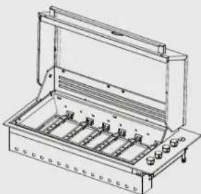
Integrated barbecue with slimline lid EQBL156AS
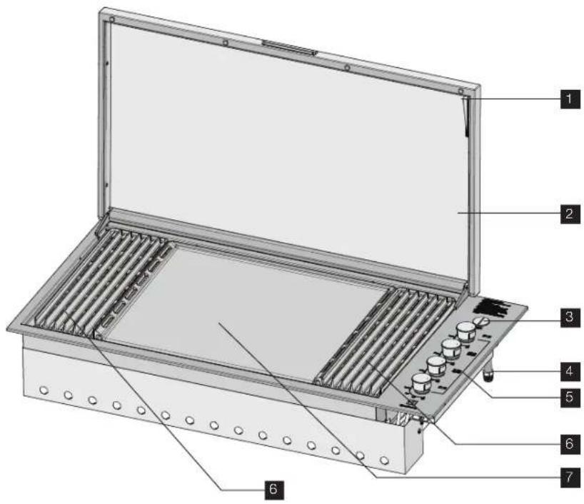
1 Pivotting leg
2 Slimline lid
3 Battery cover
4 Gas connection point
5 Burner controls
6 Grill
7 Maxiplate
8 Removable oil reservoir located at front of cooking surface (not illustrated)
9 Flame tamers x 2 located under grills (not illustrated)
Integrated barbecue with roasting hood EQBH156AS
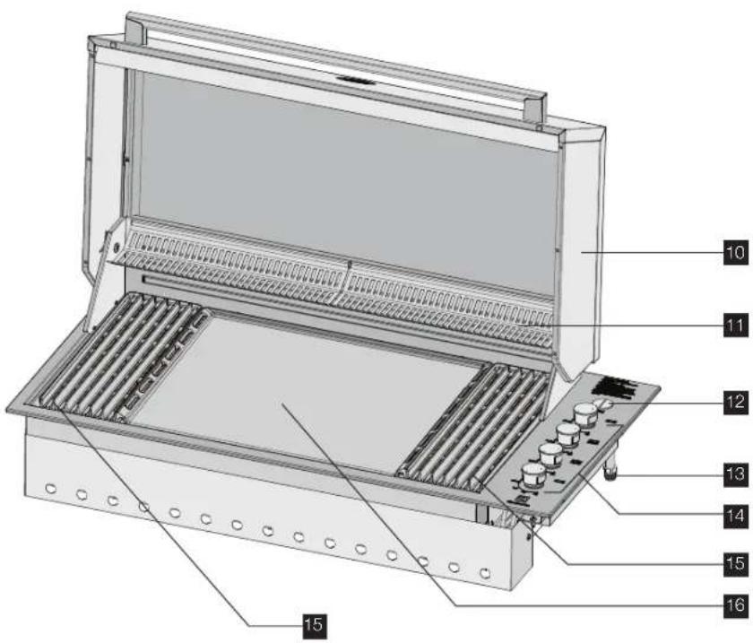
10 Roasting hood
11 Warming racks
12 Battery cover
13 Gas connection point
14 Burner controls
15 Grill
16 Maxiplate
17 Removable oil reservoir located at front of cooking surface (not illustrated)
18 Flame tamers x 2 located under grills (not illustrated)
PARTS
Contents of your barbecue pack:
| Description QTY | |
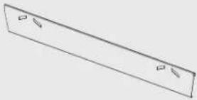 | Rear heat 1 shield |
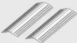 | Flame tamers 2 |
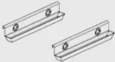 | Oil reservoirs 2 |
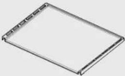 | Cast Iron 1 Maxiplate |
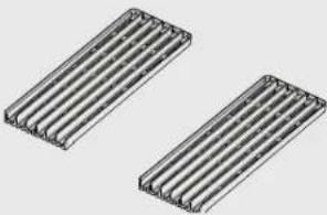 | Cast iron grill 2 |
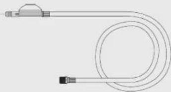
natural_image
Pure diagram of a U-shaped tube with connectors and a central loop (no text or symbols)1 Plastic bag containing this instruction book, labels, LPG adaptor, 1 fibre washer, match holder and chain
natural_image
Technical line drawing of a mechanical enclosure or enclosure with internal compartments and mounting feet (no text or symbols)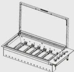
natural_image
Technical line drawing of a rectangular electronic device with multiple ports and a transparent lid (no text or symbols)GAS SPECIFICATIONS
| Gas type Propane Universal | LPG | Natural Gas | |
| Maximum gas Consumption | 71.0 MJ/h | 64.0 MJ/h | 67.2 MJ/h |
| Injector orifice diameter (mm) | 0.95mm 0.90mm 1.75mm | ||
| Number of injectors | 6 6 6 | ||
| Regulator pressure | 2.75 kPa 2.75 kPa 1.00 kPa | ||
NOTES:
- This appliance MUST be installed and serviced only by a qualified licensed person.
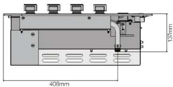
• This product is intended for outdoor use only. - This product must be installed as per the instructions which requires the installation of venting to enable the barbecue to operate correctly. Failure to provide adequate ventilation for supply of air to the appliance may result in poor burner performance or excessive heat build-up within the mounting enclosure.
- Ventilation holes in the unit must not be obscured by the installation.
natural_image
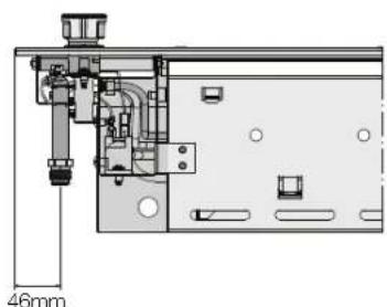
Technical diagram of a mechanical assembly with dimension标注 (46mm), showing internal components and no readable text or symbols.This barbecue is set up for PROPANE GAS and is labelled accordingly. A Universal LPG or Natural Gas conversion Kit is available if required.
Connecting the appliance to an LPG gas supply
The appliance may be supplied LPG from either:
• A 9 kg portable LPG cylinder, or
- A remote supply of LPG via fixed pipework.
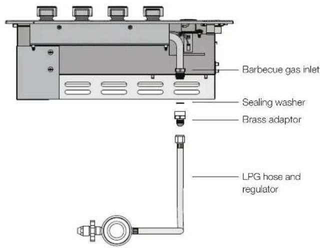
Connecting to a Portable 9kg LPG cylinder
The components required are
• LPG hose and regulator assembly to suit 9kg cylinder
- Brass adapter
- Sealing washer
To assemble the connection (refer diagram below):
- Connect the brass adapter to the barbecue gas inlet with the sealing washer in place to seal the connection.
- Connect the LPG hose and regulator to the brass adaptor.
- Connect the POL fitting at the inlet of the regulator to the valve on the LPG cylinder.
- Leak test all connections in the assembly as described under LEAK TEST PROCEDURE.
GAS BOTTLE SAFETY INFORMATION
- This appliance is designed to use a 9kg (20 lbs) gas cylinder.
- The gas cylinder must be made and marked in accordance with specifications for LPG cylinders.
- It is recommended to turn off the cylinder valve when the appliance is not in use.
- Gas cylinders must be stored in an approved housing out of reach of children.
- When disconnecting the gas bottle ensure that all the control valves are in the 'OFF' position.
- Remove the bottle from any housing in which it may be stored before disconnection.
- When reconnecting the hose to the bottle, ensure that all connections are tight before replacing in the storage compartment.
- Carry out a leakage check as detailed below after each reconnection.
Connecting to a remote supply of LPG
The components required to make this type of connection are available as an accessory and can be purchased either on the Electrolux spare parts website or by contacting the Electrolux Customer Service Centre. Refer to Accessories section on page 18 for related part numbers.
Never connect the barbecue to an unregulated LPG supply. Ensure that the supply pressure at the inlet of the barbecue is 2.75kPa.
Electrolux strongly recommends installation of a manual shut-off valve, or hose assembly with a certified quick connect that is accessible with the appliance installed, so that the appliance may be isolated from gas in the event of an emergency or for servicing.
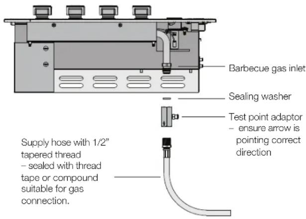
The components required are
- Brass test point adapter
- Sealing washer
To assemble the connection:
- Connect the brass test point adapter to the barbecue gas inlet with the arrow on the adapter oriented according to direction of gas flow, with the sealing washer in place to seal the connection.
- The inlet to the adapter has a standard internal 12 " pipe thread and can connect to any standard external 12 " tapered threaded connection. This connection is sealed with any thread tape or sealing compound that is suitable for gas connections. Connect the fixed LPG pipework to the inlet of the test point adapter by any suitable means in accordance with requirements of AS 5601.
- Leak test all connections in the assembly as described under LEAK TEST PROCEDURE.
After connecting the barbecue to an LPG gas supply, test the operation of the appliance:
- Check that all burners ignite (refer OPERATING INSTRUCTIONS)
- Check the operation of the burners at both maximum and turndown.
NATURAL GAS INSTALLATION
NOTE: Conversion of this unit to Natural Gas must be carried out by a qualified licensed person and a Certificate of Compliance must be issued to the owner on completion of the installation and conversion.
Converting the unit to Natural Gas
This barbecue is set up for Propane gas and is labelled accordingly. A Natural Gas conversion Kit is available as an accessory by contacting Electrolux Customer Service Centre. Refer to Accessories section on page 18.
The components required for conversion are:
- 1 x Natural gas regulator
- 1 x Small bag containing 6 x 1.75mm brass injectors
- 1 x Natural gas installation pipe
- 1 x Sealing washer
- 1 x Natural gas sticker
1. Replace 'gas type' sticker
- Locate 'Propane gas' sticker located on the barbecue gas inlet and remove it. Put the Natural gas sticker in it's place.
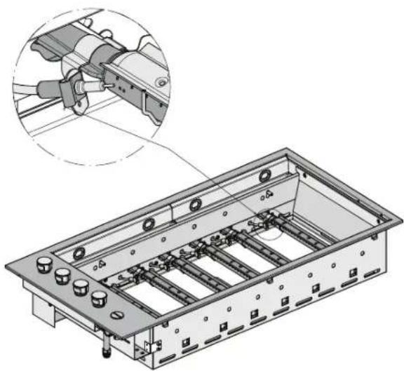
2. Change the injectors
- Remove the clip that retains the spark electrode to the burner.
natural_image
Technical illustration of a mechanical assembly with a magnified inset showing a component detail (no text or symbols present)- Release the burner from the retaining bracket by lifting as shown.
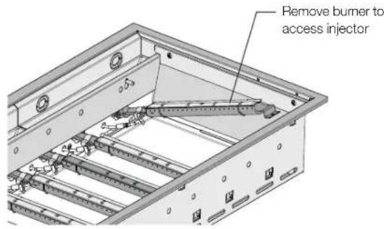
- Unscrew Propane injectors and replace with Natural Gas injectors, Natural Gas injectors have 1.75mm diameter orifice. Each Natural Gas injector is marked with the orifice size 1.75mm.
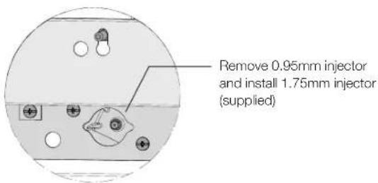
• Install burner and spark electrode with retaining clip
- Repeat for the other 5 burners
NOTE: The final step in the conversion of the barbecue to Natural Gas is the adjustment of the turndown setting. This can only be completed after the barbecue has been connected to a supply of natural gas. Refer to 'Connection to Natural Gas Supply' detailed in next section.
3. Adjust the turndown setting on the valve
- Light each burner and rotate the control knob to the lowest setting, then remove the knob from the valve shaft, and remove the grommet.
- Using a small flat-blade screwdriver adjust the turndown adjustment screw to achieve a small steady flame on the burner.
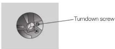
- Replace the grommet and the knob
- Recheck the operation of the burner at maximum and turndown
- Repeat procedures for all valves.
CONNECTION TO NATURAL GAS SUPPLY LEAK TEST PROCEDURE
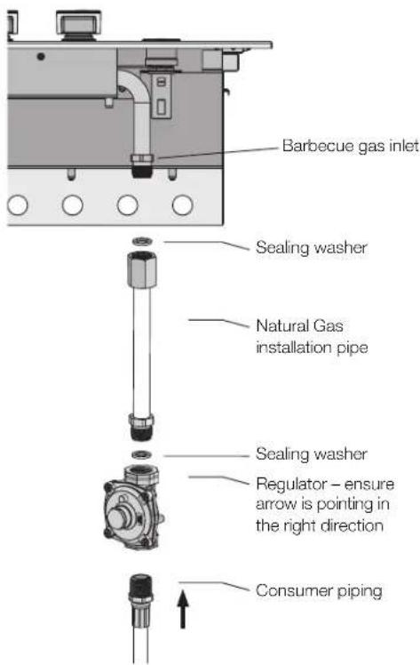
Fit Natural Gas installation pipe to the barbecue gas inlet to enable access to the regulator in the installed position. When tightening the regulator or any other connection do not over-tighten.
- Fitting the Natural Gas installation pipe
- Fit the pipe ensuring the blue sealing washer is in place. Do not over-tighten.
- Fitting the regulator
- Fit the regulator ensuring the blue sealing washer is in place and the arrow indicating gas flow is correct. Do not over-tighten.
- Fit the hose
- Connect consumer piping to regulator inlet.
- The Regulator inlet has 1/2" parallel pipe thread.
Preparing the unit for Natural Gas connection to mains
Natural gas connection to be made by a licensed gas fitter.
- Ensure all gas valves are in the 'OFF' position.
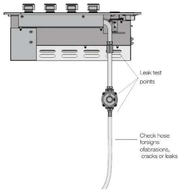
- In a small container, mix a solution of water and detergent or soap.
- After connection of the hose, turn on the valve at the gas bottle or mains as appropriate.
- Using a brush apply the solution to the gas connection points and look for bubbles forming.
• Bubbling will indicate a leak. - Turn off the valve and re-tighten the joint. Repeat the leak test.
- If the leak persists, turn of the gas at the isolation valves and contact a licensed gas fitter to correct.
INSTALLATION WARNINGS

WARNING!
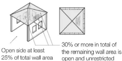
- This appliance shall only be used in an above ground, open air situation with natural ventilation, without stagnant areas, where gas leakage and products of combustion are rapidly dispersed by wind or natural convection. This barbecue has been designed for outdoor use only. Refer to diagrams below.
- Never install this barbecue inside any building, garage, shed or breezeway or inside a boat, caravan or recreational vehicle. This is to prevent the possibility of fire or carbon monoxide poisoning or asphyxiation.
- Any enclosure in which this appliance is installed shall comply with one of the following:
- An enclosure with walls on all sides, but at least one permanent opening at the ground level and no overhead covering.
- Within a partial enclosure that includes an overhead cover and no more than 2 walls.
- Within a partial enclosure that includes an overhead cover and more than 2 walls, the following shall apply:
- At least 25% of the total wall area is completely open and at least 30% of the remaining wall area is open and unrestricted.
- In the case of balconies, at least 20% of the total of the side, back and front wall areas shall be and remain open and unrestricted.
Outdoor area example 1
Outdoor area example 2
Outdoor area example 3
Both ends open
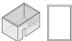
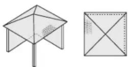
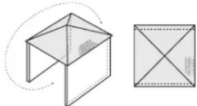
natural_image
Geometric diagram showing a 3D cube with an adjacent square with internal diagonals (no text or symbols)Outdoor area example 4
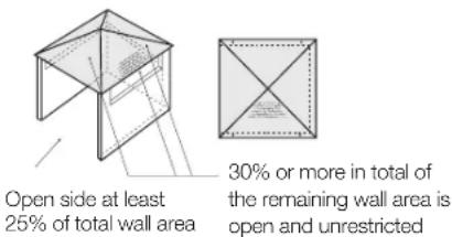
Outdoor area example 5
INSTALLATION INSTRUCTIONS
Choosing a location
When planning the location and preparing the installation structure for this appliance note the following:
- This appliance must be installed in accordance with Australian Standard AS 5601 and in accordance with local authority.
- Requirements in these instructions for clearances to combustible materials also apply to combustible materials that have non-combustible materials attached to their surface.
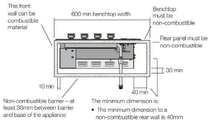
- This appliance must be installed such that no part of the appliance is in contact with or within 10mm of any combustible material.
- The minimum clearance to a vertical wall or splashback above bench level and behind the barbecue that is made from combustible material is 450mm for a model with a roasting hood and 200mm for a slimline lid model.
- The vertical clearance above the cooking surface to any combustible materials must be at least 1000mm.
- The minimum clearance to a vertical wall above bench level made from combustible material is
o 150mm from the left side of the barbecue, and
o 20mm from the right side.
- When using LPG in an enclosure ventilation must be provided. Gas is highly explosive and can cause serious injury and damage to property if allowed to accumulate and then be ignited.
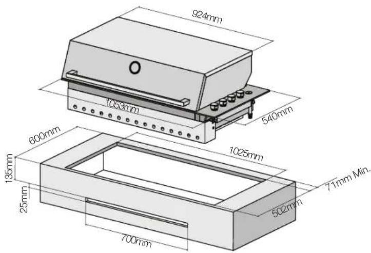
- This barbecue is intended to be built into a benchtop with a minimum depth (front to rear) of 600 mm.
- Avoid windy positions as this will affect cooking performance and burner efficiency. If this situation cannot be avoided some shielding may be necessary.
The mounting enclosure
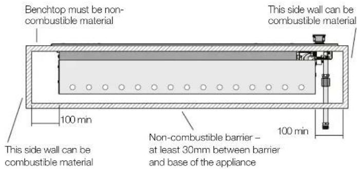
- The barbecue requires a non-combustible barrier under the barbecue to prevent excessive temperatures being accessed. The barrier panel is to be placed at least 30mm under the base of unit.
- The benchtop that supports the barbecue must be constructed from non-combustible material. Suitable materials include masonry, granite, marble, Hardiplank®, Villaboard® over a metal frame, or tiles on a non-combustible substrate.
- This appliance requires venting. The vent opening can be in either of two alternative locations – Front wall below the bench, or the non-combustible barrier under the barbecue. Refer to diagrams {on next page} for vent specification and location alternatives.
- This appliance can be mounted either in an island type bench or a bench with a splashback. Please read the specific requirements for each mounting situation.
- For ULPG use, cabinetry below the barbecue must have low level venting to prevent the possibility of LPG accumulating.
- Clearances to parts of the supporting structure must be in accordance with the following diagrams:
DIMENSIONS
Side view - lid down
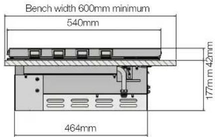
Model EQBH156AS
Side view - hood up
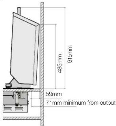
Side view - hood down
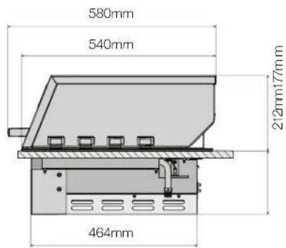
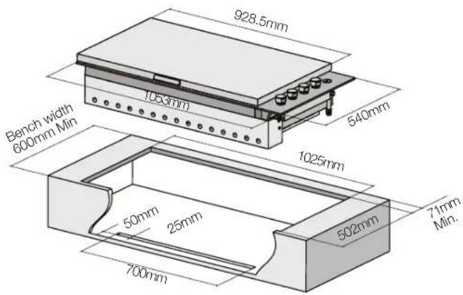
Island style installation
(example shown with barbecue with slimline line)
Alternate vent location in base of enclosure (front panel cut away for clarity)

WARNING!
This appliance requires venting. An open area as indicated must be allowed for. A suitable grille can be fitted if desired. This vent area is to allow air into the enclosure for the correct combustion of gases and for the correct exhausting of the products of combustion. The vent must be no less than 700mm x 25mm.
Installation in a bench with splashback
(example shown with barbecue with roasting hood)

WARNING!
This appliance requires venting. An open area as indicated must be allowed for. A suitable grille can be fitted if desired. This vent area is to allow air into the enclosure for the correct combustion of gases and for the correct exhausting of the products of combustion. The vent must be no less than 700mm x 25mm.
Installing in a bench with a splashback
- The splashback must be made from a non-combustible material unless it is at least 450mm from the appliance.
- Clearances between the barbecue and a combustible splashback are 200mm for the slimline lid model and 450mm for the roasting hood model.
- The minimum depth (front to rear) of the mounting bench is 600mm.
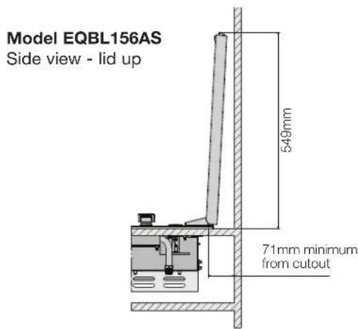
- The bench cut-out size required is 1025mm x 502mm. Refer to diagram above
- For roasting hood models there is a specific clearance required at the back of the barbecue between the splashback and the bench cut-out of 71mm minimum. This is to allow clearance for the hood to open.
Island style installation
- If this appliance is installed in an island mount, it can be centrally positioned. proved all other instructions regarding clearances to combustible materials are followed. Special attention should be given to the overall size of the island top to consider the hood open and the overhang. Please see illustration.
- The cut-out size required is 1025mm x 502mm. Refer to diagram.
GAS REQUIREMENTS
Natural Gas requirements
- The enclosure must be constructed so that access can be gained to the Natural Gas regulator at all times.
• For pipe sizing requirements for supply pipe refer to AS5601.
LPG Requirements

WARNING!
- If an LPG bottle is to be stored in the enclosure under the barbecue unit, it must be isolated from the barbecue unit with a non-combustible panel. The enclosure must comply with the requirements of AS5601.
- AS5601 ventilation requirements for cylinder storage are: Where of sheet metal or similar impervious construction there shall be ventilation openings at the top and bottom of the enclosure or recess, each opening providing a free area of at least 200cm ^2 for every cylinder enclosed.
- For LPG installations having enclosed cabinetry below the separation panel that does not contain a gas bottle, low level venting must be installed. This is to allow the gas which is heavier than air to escape from the enclosure in the situation where there may be a leak. A minimum opening of 200cm ^2 is required.
SETTING UP THE BARBECUE
Setting up the barbecue in mounting enclosure
- A match holder with attached chain has been included with the instruction manual. This is provided for manual ignition in the event the automatic ignition does not work. The free end of chain is required to be permanently fixed to the installation in a location that enables the match holder to reach each burner (refer to page 15 for manual lighting instructions).
ASSEMBLING THE BARBECUE
- Remove all components from box.
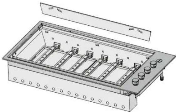
- Attach heat shield to rear of unit by inserting the three top tabs into the rear holes and sliding the shield down.
natural_image
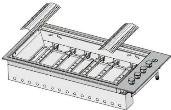
Technical illustration of an open industrial control panel with multiple slots and mounting holes (no text or symbols)- Install flame tamers (under grills) and fix back edge of flame tamer into the heat shield panel.
natural_image
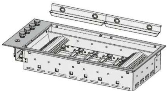
Technical illustration of a mechanical assembly with multiple slots and mounting holes (no text or symbols)- Fit oil reservoirs at front of barbecue.
natural_image
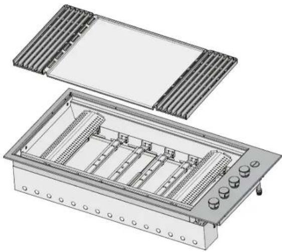
Technical illustration of an electronic device chassis with internal components and mounting brackets (no text or symbols)- Install hotplates and grills as shown, ensuring that the flame tamers are located under the grills.
NOTE: ensure that grill assemblies are orientated correctly so that the surface of the grill is sloping forward to allow oil to drain into oil reservoirs.
natural_image
Technical illustration of an open industrial enclosure with internal compartments and control knobs (no text or symbols)CONFIGURATION OPTIONS FOR HOTPLATE AND GRILLS
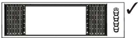
natural_image
Front view of a rectangular electronic device with vertical slots and a circular button, no visible text or symbols.Recommended configuration: Maxiplate in centre Recommended for roasting and grilling and offers the optimal heat distribution across the cooking surface.
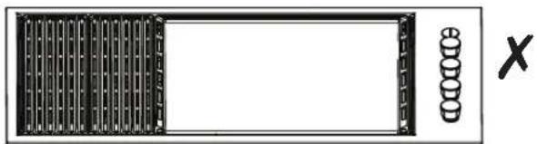
natural_image
Simple line drawing of a rectangular frame with vertical bars and a side column, no text or symbols present.Non-recommended configuration: Maxiplate on right hand May result in uneven heat distribution and increased risk of 'flare ups' on open grill surface as burners are not shielded by a flame tamer.
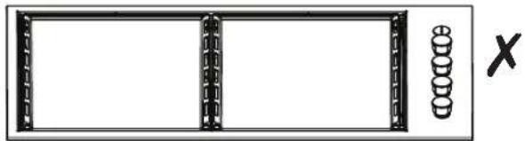
natural_image
Simple line drawing of a rectangular frame with vertical supports and a separate row of circular elements, no text or symbols present.Non-recommended configuration: two Maxiplates This may cause damage to the appliance as well as excessive temperatures in surrounding surfaces and reduced roasting performance (if roasting hood is fitted).
OPERATING INSTRUCTIONS
Control functions
Before lighting the barbecue:
- Check that all hoses and gas fittings are tight.
- Open the slimline lid or the roasting hood.
NOTE: The slimline lid is designed as a cover for weather protection. The lid is not designed to be used as a cooking hood.
- Check all control knobs are in the 'OFF' position.
- Ensure that the cooking surfaces are clean.
- Turn the gas isolation valve 'ON'.
Lighting instructions
- Do not attempt to light burners with the cooking surfaces covered.
- Read instructions before lighting.
- To light a burner, depress the knob and rotate to 'BOOST'.
- Hold for 3 seconds, release and check the flame.
- If burner did not light, turn knob to the 'OFF' position. Allow gas to disperse, then repeat lighting procedure.
Manual lighting
- If, in the event of the automatic ignition system not working, the barbecue can be lit manually.
- To light manually, fit a 40mm match to match holder provided. Pass lit match through viewing holes below the front of cooking plates down towards the burner, then rotate the knob to 'BOOST' to ignite. If ignition fails turn the control valve off and allow several minutes for the gas to disperse before attempting to light again.
- Once alight, repeat for other burners as required.
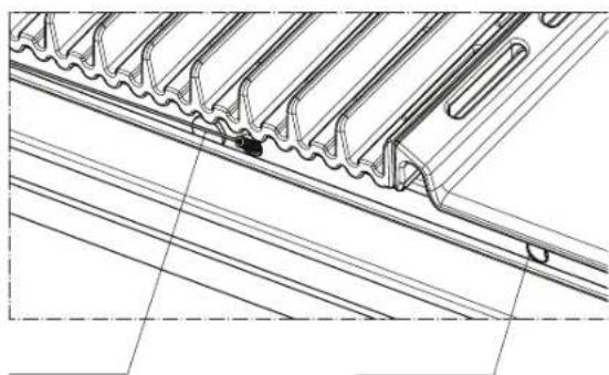
natural_image
Technical line drawing of a mechanical component with spring-like grooves and flanges (no text or symbols)Match holder Viewing holes
Preheating
For best cooking results it is recommended to preheat the barbecue prior to cooking.
- This barbecue is fitted with high power burners. In most conditions it will only be necessary to preheat the barbecue for 5 minutes before cooking can commence.
- As with most things, experience will familiarise you with the time required to achieve the desired cooking temperature.
- If the barbecue is fitted with slimline lid, it is advisable to remove the slimline lid in windy conditions.
- If the unit does not operate correctly refer to troubleshooting section on page 18.
Cooking methods:
Direct cooking / grilling
- For best cooking results testing has shown that once preheated burners can be reduced to a Medium to Low setting to maintain satisfactory cooking temperatures.
- If burners are left to run too hot there will be excessive smoking during the cooking process and subsequent burning of the food being prepared. This may also result in excessive flaring of the fat being emitted from the food.
Indirect cooking / roasting
- For barbecue models fitted with a roasting hood, it is recommended that once preheated only use the two outer burners on a low setting to maintain satisfactory cooking temperatures.
- Using more than two burners is not recommended as hood can overheat and may cause damage to the appliance. The temperature gauge indicates the desired range of roasting temperatures.
To turn the burners off
- When the cooking is complete, rotate the knob fully clockwise so the pointer is positioned at the off position.
LID SAFETY LEG - SLIMLINE LID ONLY
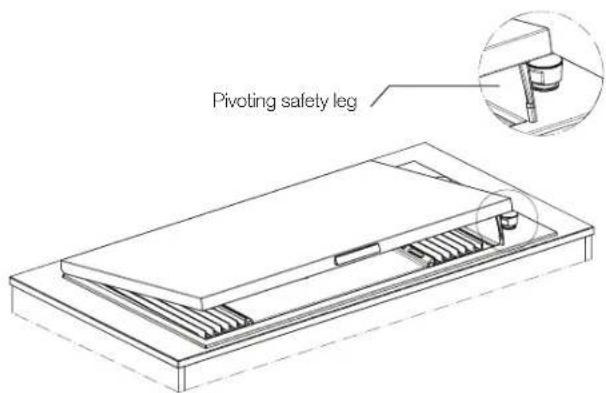
To ensure that the user remembers to turn off the gas before closing the lid, a pivoting safety leg has been fitted.
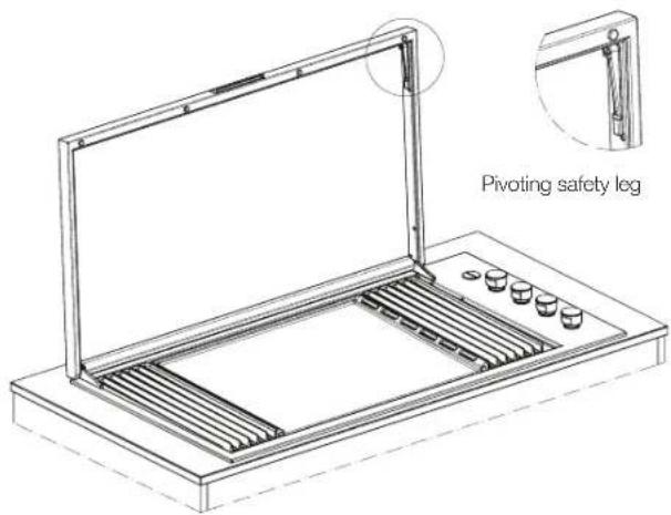
When closing the lid the safety leg will pivot forward and rest against the trim surface to prevent the lid closing. After ensuring the gas has been turned off, to fully close the lid, the leg needs to be rotated backwards.

WARNING!
THE SLIMLINE LID MUST NOT BE CLOSED WHEN THE BURNERS ARE OPERATING.
Closing the lid during burner operation can cause discolouration and damage to the lid and barbecue unit.
CLEANING AND CARE
The Electrolux Integrated barbecue has been constructed from select grade stainless steel which, if not cared for, may discolour over time. To keep your barbecue looking its best we recommend that the cooking surfaces are cleaned after every use.

WARNING!
Please ensure that your barbecue is switched off and has cooled down before following the instructions below.
Cast Iron plates
The cooking plates and grills have a porcelain enamel coating.
NOTE! Many food acids, juices, marinades and sauces contain highly acidic elements that will slowly attack the surface of the cast iron if not removed immediately after cooking.
After use remove all the solid material from the cooking surface using a brass bristled barbecue brush or plastic bristled scourer. Wipe off the remaining grease with paper toweling. Gently wash the surfaces with a cloth or a sponge and a mild detergent and hot water. Dry the components immediately and coat the cooking surface with a light layer of cooking oil. This protects the surface when not in use. Do not clean the cooking surface in a dishwasher.
Intensive cleaning cycle
Suitable for cast MaxiPlate and cast grills only!
In instances when the cooking surface becomes heavily soiled and harder to clean, the barbecue can be set-up for an intensive cleaning cycle.
To do this you must have the hood/lid fully open and remove any stainless steel attachments such as the warming racks. Turn all the burners on and set all controls to 'BOOST'. After approximately 30 minutes, this should turn any baked on food or grease to ash. Once the surface has cooled, the residual ash can be wiped clean with a damp cloth.
After cleaning, lightly season the cast MaxiPlate and cast grills with cooking oil.

WARNING!
The hood or lid must be fully open during the cleaning process.
Failure to do so can result in damage to the stainless steel surfaces and to the barbecue unit.
Other stainless steel surfaces

CAUTION!
Do not use abrasive or caustic cleaners, scourers or metal scrapers on these stainless steel surfaces as they may permanently scratch and damage your barbecue.
- Wash all stainless steel components, including the slimline lid, the roasting hood and control knobs with a soft dishcloth using hot soapy water.
- The barbecue interior can be wiped down with a soft cloth in hot soapy water. The rear panel of the interior is removable for easy cleaning.
- Ensure that all surfaces are dried with a clean dry cloth.

CAUTION!
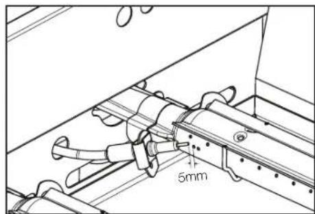
Take extra care (particularly when cleaning on and around the control knobs) to ensure that water and soapy residue do not enter the control panel, where the valves are or into the burners. Care should also be taken not to disturb the spark electrode.
A distance of 5mm should be maintained between it and the burners (see diagram below).
Cleaning inside the barbecue
The inside of the burner box should be regularly cleaned to prevent any build up of food residue.
To access the burner box remove the cooking plates and flame tamers and rear heat shield panel. The burners can then be removed (refer page 8 "Changing Injectors"). The heat shield panels in the base of the burner box can then be lifted out for cleaning purposes.
Ensure all oil and food particles are removed. After cleaning complete, re-assemble ensuring the burner is correctly located over the injector.
Cleaning the oil reservoirs
The Integrated barbecue has a unique oil management system which uses channels to drain all oil to the front into easily removed reservoirs and should be cleaned after each use.
- To remove reservoirs, pull upwards from the front of the barbecue and dispose of the contents of the catchment responsibly. Rinse oil reservoirs in warm soapy water. The reservoirs can be placed in the dishwasher if desired.

IMPORTANT!
Special note on "tea staining"
Sometimes stainless steel surfaces are affected by a brown discolouration called tea staining. This usually
occurs in areas which use high heat and can be easily removed using specialised stainless steel cleaners. For best results, we recommend that specialised cleaners be used regularly on all stainless steel components. You will find these cleaners at Electrolux spare parts outlets.

IMPORTANT!
Special note on stainless steel
The stainless steel panels may distort while in use but will return to normal when cold.
Please note that environmental conditions need to be taken into account with regards to the maintenance required on your product. In particular units installed in humid climates or seaside locations will be more susceptible to surface corrosion/discolouration over time. In these conditions Electrolux strongly recommends cleaning and drying your barbecue after every use and covering it when not in use to minimise exposure to the elements.
MAINTENANCE
The ignition system
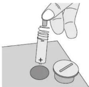
To change the battery rotate the cover anti-clockwise to release. Lift off the cover to access spring and battery. Lift out the spring and battery. Replace with a new AA battery and replace the cover. Test by depressing the knob and an audible 'clicking' sound should be heard.
NOTE: Ensure that the battery has been placed in the correct orientation.
natural_image
Illustration of a hand using a pipette to test a circular object with a plus sign, next to a circular component (no text or symbols)Air vents
The mounting enclosure air vents should be checked prior to each use, to ensure they are clear of any obstructions that may affect the free flow of air.
Stainless steel burners
Burners should be checked at least once per year and cleaned as necessary. Inspect burners to ensure no residues have been deposited and gas ports are clear.
TROUBLESHOOTING
| Problem Possible cause | Remedy | |
| Barbecue won't light | No gas Check isolation valve is ON | |
| Gas bottle empty - refill or change gas bottle | ||
| Ignition system not working | Check battery - should hear a clicking noise when the knob is depressed | |
| Replace battery | ||
| Manually light the barbecue | ||
| Ignition electrode wet or dirty | Gently clean and dry electrode ensuring position is correct | |
| Excess smoke being emitted from the cooking area | Gas valve set too high | Turn gas valves down or turn off selected burners |
| Smell of gas | Gas leak Turn off gas at the isolation valves | |
| DO NOT ATTEMPT TO LIGHT THE APPLIANCE | Check for leaks, tighten joints | |
| If problem persists call Electrolux Service | ||
| Oil not draining into removable reservoirs | Incorrect orientation of plate and grills. | Ensure plate and grills are assembled as shown on page 14. |
| Plate and grill not clean | Follow cleaning procedure for cast iron plates as detailed on page 16. | |
| Too hot when roasting | Incorrect burner settings | When roasting only use 2 outer burners on a low setting. Check temperature gauge and adjust accordingly to achieve desired roasting temperature. |
| Too hot when grilling | Incorrect burner settings | Once preheated, only use a low burner setting. Running “Boost” will quickly achieve temperatures in excess of 400°C and will char food on contact. This should be avoided. |
ACCESSORIES
To order any of the following accessories, or for more information on any other suitable accessories for this product, please contact the Electrolux Customer Service Centre.
| Accessory Item number | |
| standard inclusions+ | |
| cast iron MaxiPlate hotplate(standard, as supplied) - 1 piece | ACC171 |
| cast iron grill (standard, as supplied)- 2 pieces | ACC172 |
| optional extras* | |
| gas conversion kit - NG ACC164 | |
| gas conversion kit- reticulated hard plumbed LP | ACC165 |
| gas conversion kit - LPG ACC173 | |
| weatherproof cover (for modelEQBH156AS) | EQACBH |
| weatherproof cover (for modelEQBL156AS) | EQACBL |
| stainless steel hotplate (medium)- 1 piece | AC C174 |
| stainless steel grill (medium) - 2 pieces | ACC167 |
| cast iron hotplate (medium) - 1 piece | ACC176 |
| cast iron grill (medium) - 2 pieces | ACC177 |
| gourmet pizza pack | ACC122 |
| five piece utensils set | ACC166 |
- Standard inclusion with the product but can also be purchased separately via the Electrolux Customer Service Centre.
* Sold separately via the Electrolux Customer Service Centre. For the full range of accessories please visit electrolux.com.au or electrolux.co.nz

Electrolux Warranty
FOR SALES IN AUSTRALIA AND NEW ZEALAND
APPLIANCE: ELECTROLUX INTEGRATED BARBECUE
This document sets out the terms and conditions of the product warranties for Electrolux Appliances. It is an important document. Please keep it with your proof of purchase documents in a safe place for future reference should you require service for your Appliance.
1. In this warranty:
(a) 'acceptable quality' as referred to in clause 10 of this warranty has the same meaning referred to in the ACL;
(b) 'ACL' means Schedule 2 to the Competition and Consumer Act 2010;
(c) 'Appliance' means any Electrolux product purchased by you and accompanied by this document;
(d) 'ASC' means Electrolux authorised service centres;
(e) 'Electrolux' means Electrolux Home Products Pty Ltd of 163 O'Riordan Street, Mascot NSW 2020, ABN 51 004 762 341 in respect of Appliances purchased in Australia and Electrolux (NZ) Limited (collectively 'Electrolux') of 3-5 Niall Burgess Road, Mount Wellington, in respect of Appliances purchased in New Zealand;
(f) 'major failure' as referred to in clause 10 of this warranty has the same meaning referred to in the ACL and includes a situation when an Appliance cannot be repaired or it is uneconomic for Electrolux, at its discretion, to repair an Appliance during the Warranty Period;
(g) 'Warranty Period' means the Appliance is warranted against manufacturing defects in Australia for 60 months and in New Zealand for 24 months, following the date of original purchase of the Appliance;
(h) 'you' means the purchaser of the Appliance not having purchased the Appliance for re-sale, and 'your' has a corresponding meaning.
- This warranty only applies to Appliances purchased and used in Australia or New Zealand and used in normal domestic applications and is in addition to (and does not exclude, restrict, or modify in any way) any non-excludable statutory warranties in Australia or New Zealand.
- During the Warranty Period Electrolux or its ASC will, at no extra charge if your Appliance is readily accessible for service, without special equipment and subject to these terms and conditions, repair or replace any parts which it considers to be defective. Electrolux or its ASC may use remanufactured parts to repair your Appliance. You agree that any replaced Appliances or parts become the property of Electrolux. This warranty does not apply to light globes, batteries, filters or similar perishable parts.
- Parts and Appliances not supplied by Electrolux are not covered by this warranty.
- To the extent permitted by law, you will bear the cost of transportation, travel and delivery of the Appliance to and from Electrolux or its ASC. If you reside outside of the service area, you will bear the cost of: (a) travel of an authorised representative;
(b) transportation and delivery of the Appliance to and from Electrolux or its ASC.
In all instances, unless the Appliance is transported by Electrolux or an Electrolux authorised representative, the Appliance is transported at the owner's cost and risk while in transit to and from Electrolux or its ASC. -
Proof of purchase is required before you can make a claim under this warranty.
-
You may not make a claim under this warranty unless the defect claimed is due to faulty or defective parts or workmanship. Electrolux is not liable in the following situations (which are not exhaustive):
(a) the Appliance is damaged by:
(i) accident
(ii) misuse or abuse, including failure to properly maintain or service
(iii) normal wear and tear
(iv) power surges, electrical storm damage or incorrect power supply
(v) incomplete or improper installation
(vi) incorrect, improper or inappropriate operation
(vii) Insect or vermin infestation
(v iii) failure to comply with any additional instructions supplied with the Appliance;
(b) the Appliance is modified without authority from Electrolux in writing;
(c) the Appliance's serial number or warranty seal has been removed or defaced;
(d) the Appliance was serviced or repaired by anyone other than Electrolux, an authorised repairer or ASC.
- This warranty, the contract to which it relates and the relationship between you and Electrolux are governed by the law applicable where the Appliance was purchased. Where the Appliance was purchased in New Zealand for commercial purposes the Consumer Guarantee Act does not apply.
- To the extent permitted by law and subject to your non-excludable statutory rights and warranties, Electrolux excludes all warranties and liabilities (other than as contained in this document) including liability for any loss or damage whether direct or indirect arising from your purchase, use or non use of the Appliance.
- For Appliances and services provided by Electrolux in Australia, the Appliances come with a guarantee by Electrolux that cannot be excluded under the ACL. You are entitled to a replacement or refund for a major failure and for compensation for any other reasonably foreseeable loss or damage. You are also entitled to have the Appliance repaired or replaced if the Appliance fails to be of acceptable quality and the failure does not amount to a major failure. The benefits to you given by this warranty are in addition to your other rights and remedies under a law in relation to the Appliances or services to which this warranty relates.
- At all times during the Warranty Period, Electrolux shall, at its discretion, determine whether repair, replacement or refund will apply if an Appliance has a valid warranty claim applicable to it.
- For Appliances and services provided by Electrolux in New Zealand, the Appliances come with a guarantee by Electrolux pursuant to the provisions of the Consumer Guarantees Act, the Sale of Goods Act and the Fair Trading Act.
- To enquire about claiming under this warranty, please follow these steps: (a) carefully check the operating instructions, user manual and the terms of this warranty;
(b) have the model and serial number of the Appliance available;
(c) have the proof of purchase (e.g. an invoice) available;
(d) telephone the numbers shown below.
- You accept that if you make a warranty claim, Electrolux and its ASC may exchange information in relation to you to enable Electrolux to meet its obligations under this warranty.
Important Notice
Before calling for service, please ensure that the steps listed in clause 13 above have been followed.
| FOR SERVICEor to find the address of your nearest state service centre in AustraliaPLEASE CALL 13 13 49For the cost of a local call (Australia only) | SERVICE AUSTRALIAElectroluxELECTROLUX HOME PRODUCTSwww.electrolux.com.au | FOR SPARE PARTSor to find the address of your nearest state spare parts centre in AustraliaPLEASE CALL 13 13 50For the cost of a local call (Australia only) |
| FOR SERVICEor to find the address of your nearest authorised service centre in New ZealandFREE CALL 0800 10 66 10(New Zealand only) | SERVICE NEW ZEALANDElectroluxELECTROLUX (NZ) Ltdwww.electrolux.co.nz | FOR SPARE PARTSor to find the address of your nearest state spare parts centre in New ZealandFREE CALL 0800 10 66 20(New Zealand only) |
EBBQ60/24MNTH_Warr_Aug13
Electrolux Home Products Australia
telephone: 1300 363 640
fax: 1800 350 067
email: customercare@electrolux.com.au
web: electrolux.com.au
Electrolux Home Products New Zealand
telephone: 0800 234 234
fax: 0800 363 600
email: customercare@electrolux.co.nz
web: electrolux.co.nz
Electrolux. Thinking of you.
Share more of our thinking at electrolux.com.au or electrolux.co.nz
- WE'RE THINKING OF YOU
- BEFORE USING YOUR APPLIANCE
- CONDITIONS OF USE
- BEFORE YOU CALL
- RECORD MODEL AND SERIAL NUMBER HERE:
- CONTENTS
- SYMBOLS
- GENERAL WARNINGS
- WARNING!
- NOTE TO THE INSTALLER
- ! WARNING!
- CAUTION!
- INTEGRATED BARBECUE
- Integrated barbecue with slimline lid EQBL156AS
- PARTS
- Contents of your barbecue pack:
- NOTES:
- Connecting the appliance to an LPG gas supply
- Connecting to a Portable 9kg LPG cylinder
- GAS BOTTLE SAFETY INFORMATION
- Connecting to a remote supply of LPG
- NATURAL GAS INSTALLATION
- Converting the unit to Natural Gas
- Replace 'gas type' sticker
- Change the injectors
- Adjust the turndown setting on the valve
- CONNECTION TO NATURAL GAS SUPPLY LEAK TEST PROCEDURE
- INSTALLATION WARNINGS
- Outdoor area example 1
- Outdoor area example 2
- Outdoor area example 3
- Outdoor area example 4
- Outdoor area example 5
- INSTALLATION INSTRUCTIONS
- Choosing a location
- The mounting enclosure
- DIMENSIONS
- Island style installation
- Installation in a bench with splashback
- Installing in a bench with a splashback
- GAS REQUIREMENTS
- Natural Gas requirements
- LPG Requirements
- SETTING UP THE BARBECUE
- Setting up the barbecue in mounting enclosure
- ASSEMBLING THE BARBECUE
- CONFIGURATION OPTIONS FOR HOTPLATE AND GRILLS
- OPERATING INSTRUCTIONS
- Control functions
- Lighting instructions
- Manual lighting
- Preheating
- Cooking methods:
- Direct cooking / grilling
- Indirect cooking / roasting
- To turn the burners off
- LID SAFETY LEG - SLIMLINE LID ONLY
- THE SLIMLINE LID MUST NOT BE CLOSED WHEN THE BURNERS ARE OPERATING.
- CLEANING AND CARE
- Please ensure that your barbecue is switched off and has cooled down before following the instructions below.
- Cast Iron plates
- Intensive cleaning cycle
- The hood or lid must be fully open during the cleaning process.
- Other stainless steel surfaces
- Cleaning inside the barbecue
- Cleaning the oil reservoirs
- IMPORTANT!
- Special note on "tea staining"
- Special note on stainless steel
- MAINTENANCE
- The ignition system
- Air vents
- Stainless steel burners
- ACCESSORIES
- Electrolux Warranty
- This document sets out the terms and conditions of the product warranties for Electrolux Appliances. It is an important document. Please keep it with your proof of purchase documents in a safe place for future reference should you require service for your Appliance.
- In this warranty:
- Electrolux Home Products Australia
- Electrolux Home Products New Zealand
- Electrolux. Thinking of you.
Brand : ELECTROLUX
Model : ProLine EQBL156AS
Category : Barbecue intégré