
VMBPIR-20 - Motion detector Velbus - Free user manual and instructions
Find the device manual for free VMBPIR-20 Velbus in PDF.


User questions about VMBPIR-20 Velbus
0 question about this device. Answer the ones you know or ask your own.
Ask a new question about this device
Download the instructions for your Motion detector in PDF format for free! Find your manual VMBPIR-20 - Velbus and take your electronic device back in hand. On this page are published all the documents necessary for the use of your device. VMBPIR-20 by Velbus.
USER MANUAL VMBPIR-20 Velbus
VMBPIR-20 MOUNTING INSTRUCTIONS
CONCRETE or DRYWALL FLUSH MOUNTING -> A

natural_image
Technical line drawing of a mechanical assembly with a green component inserted, no visible text or symbols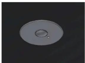
natural_image
Circular metallic object with a central hole and small dot, set against a dark background (no text or symbols)SURFACE MOUNTING -> B

natural_image
Simple line drawing of a cylindrical object with a central hole and concentric rings (no text or symbols)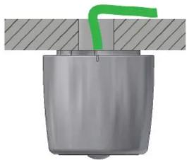
natural_image
3D diagram of a mechanical component with a green pipe inserted, no text or symbols presentSPOT MOUNTING -> C

natural_image
3D rendering of a mechanical component with springs and a central housing, mounted on a circular base (no text or symbols visible)
natural_image
Mechanical device with lever mechanism and green motion indicator (no text or symbols)I. Set the terminator switch
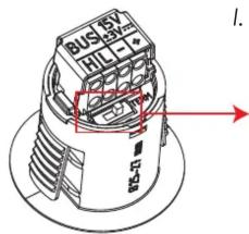
TERMINATOR ON

TERMINATOR OFF

II. Remove the BUS connector
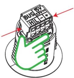
Push on the 2 sides of the cap while holding down the module with your index finger and rotate the cap.
Remove the BUS connector by pulling it up, while firmly holding down the module.

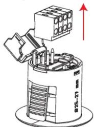
III. Connect the EIB cable

Red: Power 15V (±3V) + Black: Power GND -
White: CANbus Low L Yellow: CANbus High H
Velbus recommends a solid core EIB/KNX grade cable with 4x 0,8 mm diameter
IV. Re-mount the BUS connector onto the module

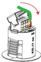

A. CONCRETE or DRYWALL FLUSH MOUNTING
- Drill holes for the module and the EIB cable feed

- Follow steps I, II, III and IV
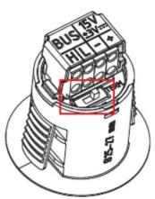
Set terminator

natural_image
Technical line drawing of a mechanical assembly with no visible text or symbolsRemove connector

Connect EIB cable

Mount connector
- Mount the module into the ceiling
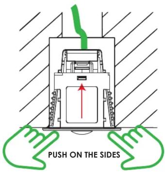

- Configure the device via the Velbuslink software (11.2 or higher)
![VIMPR-20 - Configuration Settings Dark / Light | Noise | Noise (light-dependent) | Absence | Programs Light Is activated when value is lower than 300 during at least: 1min and will stay active for Temporary Is decimated and will turn on dark output when value is higher than 500 during at least: 1min Dark Is activated when value is higher than 100 during at least: 1min and will stay active for Temporary Is decimated and will turn on light output when value is lower than 300 during at least: 1min The output light can only be triggered a second time after the output dark has been triggered first (and twice next). In other words, they can vary to be triggered alternately. Day night cycle Threshold dark (100) Threshold light (100) Current light value: Dark (100) 0 Light 0 Output dark Output light 1 1 Reaction time light [mm] Reaction time dark [mm] Show advanced features Close Latest version Refresh s initiator Action Subject s subject Size Subject](/content/2026/05/940567/images/74f62257777c5369041cf20f6dc1b45fdf87f393bfc165c1ffc1bc880c6c513e.jpg)
| B. SURFACE MOUNTING | ||||
| 1. Prepare the wiring route | 4. Mount the module into the enclosure | |||
EIB cable through ceiling Drill 16mm hole for EIB cable Drill 16mm hole for EIB cable | EIB cable on ceiling Cutout the marked piece in the enclosure Cutout the marked piece in the enclosure |  |  not push sensor! not push sensor! | |
2. Secure the mounting plate Pay attention to the orientation of the thickening at the topside! Pay attention to the orientation of the thickening at the topside! | 5. Follow step IV Mount connector Mount connector | 6. Lock the moduleTurn the module 90° into the enclosure by firmly twisting the connector anticlockwise  The module is now locked into place The module is now locked into place | ||
3. Follow steps I, II, and III Set terminator Set terminator |   Remove connectorConnect EIB cable Remove connectorConnect EIB cable | 7. Mount the enclosure onto the mounting plate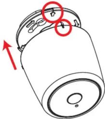 Align the tab in the enclosure with the arrow in the mounting platePush together and turn the enclosure 90° clockwise to lock it Align the tab in the enclosure with the arrow in the mounting platePush together and turn the enclosure 90° clockwise to lock it |  | |
C. SPOT MOUNTING
- Drill the hole for the spot mounting and choose the bezel size

Min. drill depth 50mm
BIG BEZEL
DRILL DIAMETER: 45mm-70mm

- Mount the springs

- Follow steps I, II, and III

Set terminator
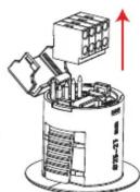
Remove connector

Connect EIB cable
- Mount the module, the bezel and the metal plate

natural_image
Technical line drawing of a mechanical assembly with springs and a central hub (no text or symbols)- Follow step IV

Mount connector
- Lock the module

Turn the module 90° into the metal plate by firmly twisting the connector clockwise
The module is now locked into place

- Mount the module in the ceiling


natural_image
Diagram of a mechanical device with a green lightning bolt emerging from its top, supported by two arms (no text or symbols)


Brand : Velbus
Model : VMBPIR-20
Category : Motion detector