
CLXI-2DIM8 - Home automation Crestron - Free user manual and instructions
Find the device manual for free CLXI-2DIM8 Crestron in PDF.


User questions about CLXI-2DIM8 Crestron
0 question about this device. Answer the ones you know or ask your own.
Ask a new question about this device
Download the instructions for your Home automation in PDF format for free! Find your manual CLXI-2DIM8 - Crestron and take your electronic device back in hand. On this page are published all the documents necessary for the use of your device. CLXI-2DIM8 by Crestron.
USER MANUAL CLXI-2DIM8 Crestron
CLTI-2DIM8/CLXI-2DIM8
Terminal Block and Module
Installation Guide
Description
The Crestron® 2-feed, 6-dimmor terminal block (CLTI 2DIV8) and module (QLXI 2DIM8) are a single unit and must be used together. They ship separately so that the terminal block wing can be accomplished before module installation. The terminal block is designed to terminate the circuit feed line and neutral) and destroy the controlled circuit load) in the volumes. The module connects to the terminal block and continues during control of eight instancescent, magnetic low voltage, mean/hold cathode, or dimmable 2-wir fluorescent lighting loads.
The maximum load for the CLX-2DIM8 is 10 A for any single circuit, or 13 A for each group of four circuits, and 26 A maximum total per module. The CLX-2DIM8 accepts two 10 A feels that must be the same phase in split phase. The unit requires 250 Vcc 50 Hz, a phase input voltage.
An oversized heat and disappears heat efficiently. There are LEDs on the module to indicate communication with a Crosnot® network, Input power to the module, and output power to the load.
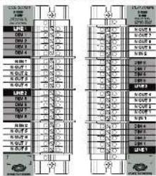
The CLTI-2DIMO terminal and CLXI-2DIMO module are shown in the following instructions. CLTI-2DIMO terminal block with Lath and Right Side CLXI-2DIMO Wiring Labels
CJ-2018 Textile Operations 29 Q 7-2018

natural_image
Pure electrical circuit lines without any symbolsAdditional Resources
Visit the road at page on the Crestron website (www.crestron.com) for additional information and the laser firmware updates. Use a GR reader application on your mobile devices to scan the GR image.


[Unreadable]
Installation
NOTE Before using the CLXI-2018, ensure the device is using the latest firmware. Check for the latest firmware for the CLXI-2018 at www.creslon.com/software. Firmware is mounted up to the device using Creeror Trustors™ software
The clerical black and metal must be returned into a Creator Automation Enclosure by a licensed electrician and in accordance with all national and local codes.
CAUTION: The equipment is for indoor use only and needs to be air-cured. Monthly in a well-ventilated area. The ambient temperature must be 0° to 40°C (32° to 160°F). The relative humidity must be 0% to 90% (noncontrolling).
NOTE: The two input lines must be the same phase or split phase.
NOTE: While not meeting to set are full product, we were that this made does not exceed 1,000 watts total.
Terminal blocks are installed along the right side of single-store enclosures and along the outside edges (left and right sides) of double-wide enclosures. Addresses are installed along the right side of single-store enclosures and side-by-side in the center of double-store enclosures. When installing machines and terminal blocks into a double-mode area, be cured to invert the unit on the right side so that they can be properly wired. Refer to the illustrations that follow when considering the motion of terminal blocks or mode less within an enclosure.
NOTE: Modules and terminal blocks must be installed into the next storage space and continue toward the top of the enclosure.
Tamaia Ples 691 (40%) 9.37% 9.75%
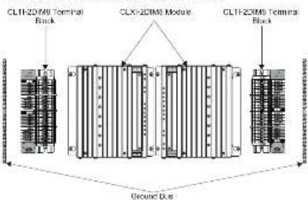
Terminal Block Installation and Field Wiring
Apply the supplied adhesive and before including the terminal block. The adhesive label provides the loading for each terminal in the terminal block and is designed to
NOTE: To install a CLTRN Circuit Breaker Terminal Book, refer to the CLTRN Installation Guide (Doc. S61) at www.crestron.com/inmarks for details.
NOTE: Both left-side and right-side adhesive wiring labels are provided. The left-side labels are used in both single- and double-wide enclosures. The right-side labels are used only in double-wide enclosures.
-
Remove the backing from the left-or-right-skin adhesive wiring label.
-
Apply the adhesive label by aligning the holes in the label with the holes on the Coedron Automation Endurance where the seminot block is to be mounted. The wrong label has beneath the terminal blocks so shown in the following diagrams.
-
Use the two supplied D × 5 mm (16 m) length self-sapping Philips pan hsd screws to ensure the nominal block to the Creator Automation Exposure.
CAUTION. Bypass jumps are provided to test circuits and to protect the module during installation. When properly occurred by five seconds, each of the last jumps on the brown and red sections of the terminal block shorts the line in to dim out so that the circuit is reorganized. Do not remove any bypass jumps can all be fixed and load wiring has been completed, the circuit has been tested for electrical faults, and the module has been installed. Refer to "Module Installation."
Furthermore, the two jumpers on the blue sections of the terminal block to the neutral line to the neutral cuts. These jumpers should never be removed.
NOTE: Use copper conductors only—rated 75°C or greater.
-
Turn off the circuit breakers
-
Connect the circuit feed line and neutral and controlled circuit [load] wires to the terminal blocks per the markings provided on the wiring label (see shown in the following diagram). Terminal blocks accept one 2.5-8 mm wire. Strips the wires to 12 mm (1/2 to 1) other terminal blocks to 1.5m
-
Term is able to ground areas at the grounding terminal mass that are available in the cabinet. Tighten the grounding terminal occurs to 4 Nm (2.5-6 mm²), 4.5 Nm (10 mm²), in 5.1 Nm (18-25 mm²).
-
Test each circuit for electrical faults by turning on each of the circuit breakers and checking that the breakers do not trip and that power is delivered to the proper loads. NOTE: If including in a CAENB, complete the installation with a CAENB EP Block, Rate, Refer to the CAENB (Doc. 8063) for details.
Asing the Terminal Block to the Food and Locally

flowchart
graph TD
    A["LINE 1: Connection from a 16A Circuit Breaker"] --> B["Ground Bus"]
    A --> C["Neutral"]
    A --> D["Line 2: Connection from a 16A Circuit Breaker"]
    A --> E["Neutral Capacitor"]
    B --> F["To Load"]
    C --> G["Load"]
    D --> H["Medium Location Label"]
    E --> I["Low-Side Vial/Level"]
    F --> J["Terminal Block"]
    G --> K["Line 1"]
    H --> L["Line 2"]
    I --> M["Line 3"]
    J --> N["Line 4"]
    K --> O["Line 5"]
    L --> P["Line 6"]
    M --> Q["Line 7"]
    N --> R["Line 8"]
    O --> S["Line 9"]
    P --> T["Line 10"]
    Q --> U["Line 11"]
    R --> V["Line 12"]
    S --> W["Line 13"]

CRESTRON
(2) The Taiwan Bank to the Road and Local West-State Church (West Resourc)

Module installation
CAUTION: The module contains electrostatic sensitive devices (ESDs). The unit must be handled from the metal chaser. Do not touch the PC board or components
Instal the mcmnses after the terminal blocks are insted and the endoms has been completely wired.
-
Use the four supplied 83 x 6 mm (1/4 in) length soft-tapping Phillips pan head screws to set up the work in the wicks no.
-
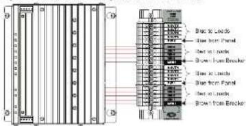
As shown in the wiring diagram on the next page, connect the wires from the module to the terminal block. Each wire sets the module directly in line with, and is the same color as, the terminal to which it should be connected. Wire are prescribed to 13 mm (1/2 m), right to 1 Nm.
-
If the module is being installed above another module within the enclosure, attach the supplied module to connect cable to the two modules. The illustration that follows shows the area within a double-wide enclosure where the corners of four modules meet.
NOTE: One wire on the module interconnect cable may be a different color from the red. The color loss is lower in its concentration during detection.
Use Mechanical Contract Data to Write Contract Note to Another

C. Turn on the circuit breakers and verify that the green PWR LED on the module lights. The breakers can not trip, but power is delivered to the loads.
- Turn off the circuit breakers.
NOTE: Before the bypass jumpers are removed, the control system that provides functionality to the system should be properly connected and programmed.
- Remove the bypass jumpers on the brown and red sections of the terminal block. The jumpers on the blue sections of the terminal block must remain installed. Refer to the figure that follow for reference.
Bring the Jewarl Block to the Module Single Edition and Left Side Double-Role Enclosures.

Remove the 100% of cases after Testing (P-67-Side Mounted CT-TOPWR shown)

Using the terminal block to the module High Side Double-Wide Unbounded
Remove the American State of Texas (New York State of Texas, New York State of Texas, New York State of Texas, New York State of Texas, New York State of Texas, New York State of Texas, New York State of Texas, New York State of Texas, New York State of Texas, New York State of Texas, New York State of Texas, New York State of Texas, New York State of Texas, New York State of Texas, New York State of Texas, New York State of Texas, New York State of Texas, New York State of Turkey, New York State of Turkey, New York State of Turkey, New York State of Turkey, New York State of Turkey, New York State of Turkey, New York State of Turkey, New York State of Turkey, New York State of Turkey, New York State of Turkey, New York State of Turkey, New York State of Turkey, New York State of Turkey, New York State of Turkey, New York State of Turkey, New York State of Turkey, New York State of Turkey, New York States of the United Kingdom

7. Turn on the circuit breakers.

8. If the program is real starting and, loads can be loaded by using Local made
Test the Loads
If the control system program is not running yet, use Local mode to test that each load is operating and connected to the proper output on the modals.
-
Press the SETUP button momentarily (less than three seconds) to enter Local mode. The SETUP LED and output LED 1 illustrate. Power is applied to the devices connected to output 1.
-
Press the SETUP button again to turn off output 1 and turn off output 2.
- Press the SETUP button again to test each of the remaining outputs.
- After testing the last minute, power the SETUP action again in between of minutes.
- Press the SETUP button once more to turn off all outputs and LEDs and exit Local Monitor.
As of the state of manufacturing, the device has been loaded and then to comply with specifications he
CE TME 10
CE
The product summary can be found at www.thelebon.com/tamaris.
The specific patents that cover Canadian products and hate as pharmaceuticals are
Certain Credit product orders can open source software. For specific information, please visit www.credman.com/100000-173
Crestron, the Crestron logo, Creener, and Crestron Toolbox are other trademarks of new stores.
indemnior of Greaten Electronics, Inc. in the United States and other countries. Other
maximum, log ste de 2002/1974, and face/rises may be used in a document to rest to offer the entire claiming the marks and tags of their products. Create icons are complete.
the closest matching the mania of the 6000 proclera. Greatness and the opportunity of interest in a maria and national others. Greatness is not possible for any other (geography) or
[Unreadable]
The number of members by the technical industry department is called
©2016 Canadian Electrical, Inc.
Creativity Electronics, Inc.
15.000000000000000000000000000000000000000000
[Unreadable]
2016年1月1日
Inhibition Guide - DOC. 64110
(201300)
Specifications subject to
[Unreadable]
Brand : Crestron
Model : CLXI-2DIM8
Category : Home automation